CN113348600B - Cable preparation device - Google Patents
Cable preparation deviceDownload PDFInfo
- Publication number
- CN113348600B CN113348600BCN201980089864.6ACN201980089864ACN113348600BCN 113348600 BCN113348600 BCN 113348600BCN 201980089864 ACN201980089864 ACN 201980089864ACN 113348600 BCN113348600 BCN 113348600B
- Authority
- CN
- China
- Prior art keywords
- cable
- tool
- cutting
- cutting tool
- depth
- Prior art date
- Legal status (The legal status is an assumption and is not a legal conclusion. Google has not performed a legal analysis and makes no representation as to the accuracy of the status listed.)
- Active
Links
Images


Classifications
- H—ELECTRICITY
- H02—GENERATION; CONVERSION OR DISTRIBUTION OF ELECTRIC POWER
- H02G—INSTALLATION OF ELECTRIC CABLES OR LINES, OR OF COMBINED OPTICAL AND ELECTRIC CABLES OR LINES
- H02G1/00—Methods or apparatus specially adapted for installing, maintaining, repairing or dismantling electric cables or lines
- H02G1/12—Methods or apparatus specially adapted for installing, maintaining, repairing or dismantling electric cables or lines for removing insulation or armouring from cables, e.g. from the end thereof
- H02G1/1202—Methods or apparatus specially adapted for installing, maintaining, repairing or dismantling electric cables or lines for removing insulation or armouring from cables, e.g. from the end thereof by cutting and withdrawing insulation
- H02G1/1248—Machines
- H02G1/1265—Machines the cutting element rotating about the wire or cable
- H—ELECTRICITY
- H02—GENERATION; CONVERSION OR DISTRIBUTION OF ELECTRIC POWER
- H02G—INSTALLATION OF ELECTRIC CABLES OR LINES, OR OF COMBINED OPTICAL AND ELECTRIC CABLES OR LINES
- H02G1/00—Methods or apparatus specially adapted for installing, maintaining, repairing or dismantling electric cables or lines
- H02G1/12—Methods or apparatus specially adapted for installing, maintaining, repairing or dismantling electric cables or lines for removing insulation or armouring from cables, e.g. from the end thereof
- H02G1/1202—Methods or apparatus specially adapted for installing, maintaining, repairing or dismantling electric cables or lines for removing insulation or armouring from cables, e.g. from the end thereof by cutting and withdrawing insulation
- H02G1/1248—Machines
- H02G1/127—Features relating to cutting elements
- H—ELECTRICITY
- H04—ELECTRIC COMMUNICATION TECHNIQUE
- H04N—PICTORIAL COMMUNICATION, e.g. TELEVISION
- H04N7/00—Television systems
- H04N7/18—Closed-circuit television [CCTV] systems, i.e. systems in which the video signal is not broadcast
- H04N7/188—Capturing isolated or intermittent images triggered by the occurrence of a predetermined event, e.g. an object reaching a predetermined position
- H—ELECTRICITY
- H04—ELECTRIC COMMUNICATION TECHNIQUE
- H04N—PICTORIAL COMMUNICATION, e.g. TELEVISION
- H04N23/00—Cameras or camera modules comprising electronic image sensors; Control thereof
- H04N23/50—Constructional details
- H04N23/51—Housings
Landscapes
- Engineering & Computer Science (AREA)
- Multimedia (AREA)
- Signal Processing (AREA)
- Removal Of Insulation Or Armoring From Wires Or Cables (AREA)
- Laying Of Electric Cables Or Lines Outside (AREA)
Abstract
Translated fromChinese
Description
Translated fromChinese本申请是2019年12月20日提交的国际专利申请第PCT/US2019/067956号的国家阶段专利申请,其要求于2019年5月10日提交的美国临时专利申请第62/846,351号和于2018年12月21日提交的美国临时专利申请第62/784,214号二者的权益,每个申请的全部内容通过引用并入本文。This application is a National Phase Patent Application of International Patent Application No. PCT/US2019/067956, filed December 20, 2019, which claims U.S. Provisional Patent Application No. 62/846,351, filed May 10, 2019 and filed in 2018 US Provisional Patent Application No. 62/784,214, filed December 21, 2009, the entire contents of each application are incorporated herein by reference.
技术领域technical field
本公开内容涉及用于电力设施的电气设备领域,包括电缆及附件。The present disclosure relates to the field of electrical equipment for electrical installations, including cables and accessories.
背景技术Background technique
电网包括在不同位置和条件(例如,地上、地下、寒冷天气气候、炎热天气气候等)下操作的许多部件。电网可以包括成百上千个分立部件,例如变压器、电缆、电缆附件(例如,电缆接头、终端)等,并且电网中的故障可能由任何单个部件或部件集合中的故障导致。电缆的安装是易于出错的人工处理,这可能导致电缆或电缆附件中的故障。The electrical grid includes many components that operate in different locations and conditions (eg, above ground, underground, cold weather climates, hot weather climates, etc.). A grid may include hundreds or thousands of discrete components, such as transformers, cables, cable accessories (eg, cable splices, terminals), etc., and faults in the grid may result from faults in any single component or collection of components. The installation of cables is an error-prone manual process which can lead to faults in the cables or cable accessories.
发明内容Contents of the invention
本公开内容提供了用于制备用于在电网中使用的连接至电缆附件的电缆的技术。根据本公开内容的示例,电缆制备装置被配置成自动去除电缆的一个或更多个层,以用于将电缆耦接至电缆附件(例如,电缆接头本体或终端)。在一个示例中,电缆制备装置包括工具头,该工具头具有被配置成切割电缆的各种层的一个或更多个切割工具和多个辊,所述多个辊被配置成在切割工具切割电缆的层时将电缆保持在适当的位置。电缆制备装置被配置成自动调节多个辊的径向深度和/或切割工具的径向深度。在一个示例中,电缆制备装置通过切穿电缆的护套层来产生保持带(retention band)。保持带可以防止电缆的内部层磨损、变松或以其他方式干扰后续的切割。在另一示例中,电缆制备装置在护套层中产生突片(tab)(例如,在产生保持带之后)。在护套层中产生突片可以使得电缆制备装置能够在切割护套层的内部部分时将护套从内部层抬起,这可以简化护套层的去除并且潜在地减少或消除对电缆的内部层(例如,护罩层)的损坏。The present disclosure provides techniques for preparing cables for connection to cable accessories for use in electrical grids. According to an example of the present disclosure, a cable preparation device is configured to automatically remove one or more layers of a cable for coupling the cable to a cable accessory (eg, a cable gland body or terminal). In one example, a cable preparation apparatus includes a tool head having one or more cutting tools configured to cut various layers of a cable and a plurality of rollers configured to cut Keep the cables in place while layering the cables. The cable preparation device is configured to automatically adjust the radial depth of the plurality of rollers and/or the radial depth of the cutting tool. In one example, the cable preparation device creates a retention band by cutting through the jacket of the cable. The retaining tape keeps the inner layers of the cable from fraying, coming loose, or otherwise interfering with subsequent cuts. In another example, the cable preparation device creates tabs in the jacket layer (eg, after creating the retention strip). Creating tabs in the jacket layer can enable the cable preparation device to lift the jacket from the inner layer when cutting the inner part of the jacket layer, which can simplify the removal of the jacket layer and potentially reduce or eliminate the inner part of the cable. Layer (eg, shield layer) damage.
以这种方式,该电缆制备装置可以比其他技术更快地制备电缆,并且更精确地控制对电缆的一个或更多个层的切割的切割深度和削减长度(cutback length)。更精确地切割电缆的层可以减少电缆(例如,电缆接头中)中的缺损。例如,更精确地切割层可以减少空气空隙,并且因此降低局部放电事件的概率和/或数量。减少局部放电事件的概率和/或数量可以降低电缆的故障事件的概率并且增加电缆的预期寿命。减少故障事件的概率可以增加电网的可靠性。此外,增加电缆的预期寿命可以降低构建、操作和维护电网的成本。In this way, the cable preparation device can prepare cables faster than other techniques and more precisely control the cut depth and cutback length of the cuts to one or more layers of the cable. Cutting the layers of the cable more precisely can reduce defects in the cable (eg, in cable splices). For example, cutting layers more precisely can reduce air voids, and thus reduce the probability and/or number of partial discharge events. Reducing the probability and/or number of partial discharge events can reduce the probability of failure events of the cable and increase the life expectancy of the cable. Reducing the probability of failure events can increase the reliability of the grid. Additionally, increasing the life expectancy of cables reduces the cost of building, operating and maintaining the grid.
在一个示例中,电缆制备装置被配置成去除电缆的一个或更多个层。该装置包括可旋转工具头和工具定位驱动器。可旋转工具头包括多个辊和至少一个切割工具。工具定位驱动器被配置成插入可旋转工具头中以调节多个辊的径向深度或至少一个切割工具的径向深度。In one example, the cable preparation device is configured to remove one or more layers of the cable. The device includes a rotatable tool head and a tool positioning drive. The rotatable tool head includes a plurality of rollers and at least one cutting tool. A tool positioning drive is configured to be inserted into the rotatable tool head to adjust the radial depth of the plurality of rollers or the radial depth of the at least one cutting tool.
在另一示例中,电缆制备装置被配置成去除电缆的一个或更多个层。该装置包括可旋转工具头,可旋转工具头包括多个辊和至少一个切割工具。电缆制备装置被配置成通过至少被配置成执行以下操作来去除电缆的一个或更多个层:将至少一个切割工具插入电缆中至第一深度;在至少一个切割工具处于第一深度的情况下使工具头旋转部分旋转以在一个或更多个层的端部处在一个或更多个层中产生突片;将至少一个切割工具缩回至第二深度;以及在至少一个切割工具处于第二深度的情况下通过在工具头相对于电缆的中心轴线从突片纵向地移动时使工具头绕电缆旋转来执行螺旋切割。In another example, the cable preparation device is configured to remove one or more layers of the cable. The apparatus includes a rotatable tool head including a plurality of rollers and at least one cutting tool. The cable preparation device is configured to remove one or more layers of the cable by at least being configured to: insert at least one cutting tool into the cable to a first depth; with the at least one cutting tool at the first depth rotating the tool head rotating portion to create tabs in the one or more layers at ends of the one or more layers; retracting the at least one cutting tool to a second depth; and retracting the at least one cutting tool to a second depth; In the case of two depths helical cutting is performed by rotating the tool head around the cable as the tool head moves longitudinally from the tab relative to the central axis of the cable.
在又一示例中,电缆制备装置被配置成去除电缆的一个或更多个层。该装置包括可旋转工具头,可旋转工具头包括多个辊和至少一个切割工具。电缆制备装置被配置成通过至少被配置成执行以下操作来去除电缆的一个或更多个层:通过至少被配置成执行以下操作来产生电缆的一个或更多个层的护套层的保持带:将工具头定位在距电缆的端部一定距离的纵向起始位置处;将至少一个切割工具朝向电缆的中心插入至目标切割深度;以及在至少一个切割工具处于目标切割深度的情况下使工具头绕电缆旋转;以及响应于产生保持带,移除在纵向起始位置与由与护套层相关联的目标削减长度限定的纵向位置之间的护套层的内部部分。In yet another example, the cable preparation device is configured to remove one or more layers of the cable. The apparatus includes a rotatable tool head including a plurality of rollers and at least one cutting tool. The cable preparation apparatus is configured to remove one or more layers of the cable by at least being configured to: produce a retaining strip of the jacket layer of the one or more layers of the cable by at least being configured to: : positioning the tool head at a longitudinal starting position at a distance from the end of the cable; inserting at least one cutting tool towards the center of the cable to a target cutting depth; and with the at least one cutting tool at the target cutting depth rotating the head around the cable; and removing an inner portion of the jacket layer between a longitudinal starting position and a longitudinal position defined by a target cut length associated with the jacket layer in response to creating the retaining band.
在附图和下面的描述中阐述了本公开内容的一个或更多个示例的细节。根据说明书和附图以及根据权利要求书,本公开内容的其他特征、目的和优点将是明显的。The details of one or more examples of the disclosure are set forth in the accompanying drawings and the description below. Other features, objects, and advantages of the disclosure will be apparent from the description and drawings, and from the claims.
附图说明Description of drawings
图1A和图1B是示出根据本公开内容的各种技术的用于制备用于在电网内使用的电缆的示例系统的概念图。1A and 1B are conceptual diagrams illustrating example systems for preparing electrical cables for use within an electrical grid, according to various techniques of this disclosure.
图2A和图2B是根据本公开内容的各种技术的被配置成制备用于安装至电网的电缆的电缆制备装置的概念图。2A and 2B are conceptual diagrams of a cable preparation device configured to prepare cables for installation to a power grid, according to various techniques of the present disclosure.
图3A和图3B是根据本公开内容的各种技术的示例电缆制备装置的概念图。3A and 3B are conceptual diagrams of example cable preparation devices according to various techniques of this disclosure.
图4A和图4B是示出根据本公开内容的各种技术的示例工具头的细节的概念图。4A and 4B are conceptual diagrams illustrating details of an example tool head according to various techniques of this disclosure.
图5是示出根据本公开内容的各种技术的示例工具头的细节的概念图。5 is a conceptual diagram illustrating details of an example tool head according to various techniques of this disclosure.
图6A至图6F是示出根据本公开内容的各种技术的用于操作示例工具头的示例技术的概念图。6A-6F are conceptual diagrams illustrating example techniques for operating an example tool head in accordance with various techniques of this disclosure.
图7是示出根据本公开内容的各种技术的示例电缆制备技术的细节的概念图。7 is a conceptual diagram illustrating details of an example cable preparation technique according to various techniques of this disclosure.
图8是示出根据本公开内容的各种技术的使用电缆制备装置制备示例电缆的示例技术的细节的概念图。8 is a conceptual diagram illustrating details of an example technique for preparing an example cable using a cable preparation device in accordance with various techniques of this disclosure.
图9A至图9D是示出根据本公开内容的各种技术的用于使用示例电缆制备装置制备示例电缆的示例技术的概念图。9A-9D are conceptual diagrams illustrating example techniques for preparing example cables using example cable preparation devices, according to various techniques of this disclosure.
图10A至图10C是示出根据本公开内容的各种技术的使用示例电缆制备装置制备示例电缆的示例技术的细节的概念图。10A-10C are conceptual diagrams illustrating details of an example technique for preparing an example cable using an example cable preparation device in accordance with various techniques of this disclosure.
图11是示出根据本公开内容的各种技术的使用电缆制备装置制备示例电缆的示例技术的细节的概念图。11 is a conceptual diagram illustrating details of an example technique for preparing an example cable using a cable preparation device in accordance with various techniques of this disclosure.
图12是示出根据本公开内容的各种技术的耦接两个电缆的示例电缆附件和连接器的细节的概念图。12 is a conceptual diagram showing details of an example cable accessory and connector coupling two cables according to various techniques of this disclosure.
图13A至图13C是示出根据本公开内容的各种技术的使用具有摄像机的电缆制备装置制备示例电缆的示例技术的概念图。13A-13C are conceptual diagrams illustrating example techniques for preparing an example cable using a cable preparation device with a camera, according to various techniques of this disclosure.
图14是示出根据本公开内容的各种技术的使用具有摄像机的电缆制备装置制备示例电缆的示例技术的细节的概念图。14 is a conceptual diagram illustrating details of an example technique for preparing an example cable using a cable preparation device with a camera in accordance with various techniques of this disclosure.
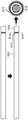
图15是示出根据本公开内容的各种技术的示例制备的电缆的概念图。FIG. 15 is a conceptual diagram illustrating a cable prepared according to an example of various techniques of the present disclosure.
图16是示出根据本公开内容的各种技术的由示例电缆制备系统执行的示例操作的流程图。16 is a flowchart illustrating example operations performed by an example cable preparation system in accordance with various techniques of this disclosure.
图17A和图17B是示出电缆中的示例缺损的概念图。17A and 17B are conceptual diagrams illustrating example defects in cables.
应当理解,在不脱离本发明的范围的情况下,可以使用实施方式并且可以进行结构的改变。附图不一定按比例绘制。在附图中使用的相似的附图标记指代相似的部件。然而,将理解的是,使用附图标记来指代给定附图中的部件不旨在限制利用相同附图标记另一附图中的该部件。It is to be understood that the embodiments may be utilized and structural changes may be made without departing from the scope of the present invention. The drawings are not necessarily drawn to scale. Like reference numerals are used in the drawings to refer to like parts. It will be understood, however, that the use of a reference number to refer to a component in a given figure is not intended to limit that component in another figure with the same reference number.
具体实施方式detailed description
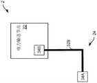
图1A和图1B是示出用于自动制备用于电网内的电缆的示例系统2的概念图。系统2表示其中一个或更多个电力线24将电力从电力源(例如,发电厂)提供至一个或更多个客户(例如,企业、家庭、政府设施等)的物理环境。系统2包括多件电气设备,例如一个或更多个电力输送节点22、一个或更多个电力线24以及一个或更多个电缆制备装置50。1A and 1B are conceptual diagrams illustrating an
电力输送节点22可以包括(例如,直接从电源或间接经由另一电力输送节点22)接收电力的一个或更多个输入线和直接或间接地(例如,经由另一电力输送节点22)向客户(例如,家庭、企业等)分配电力的一个或更多个输出线。电力输送节点22可以包括变压器以升高或降低电压。在一些示例中,电力输送节点22可以是将电力分配至附近家庭的相对小的节点,例如电气柜、柱安装式变压器(pole-mount transformer)或垫安装式变压器(pad-mount transformer)。作为另一示例,电力输送节点22可以是向其他电力输送节点(例如,配电变电站)分配电力的相对大的节点(例如,传输变电站),使得其他电力输送节点进一步向客户(例如,家庭、企业等)分配电力。The
电力线24可以将电力从电力源(例如,发电厂)传输至电力客户,例如企业或家庭。电力线24可以是地下的、水下的或架空悬挂的(例如,从木杆、金属结构等架空悬挂)。电力线24可以用于以相对高的电压(例如,与用于家庭内的电气线缆——根据应用和地理区域其可以传输约12伏特与约240伏特之间的电力——相比)进行电力传输。例如,电力线24可以传输大约600伏特以上(例如,约600伏特与约1000伏特之间)的电力。然而,应当理解,电力线24可以在任何电压和/或频率范围内传输电力。例如,线24可以在不同的电压范围内传输电力。在一些示例中,第一类型的线24可以传输大约1000伏特以上的电压,例如以用于在住宅或小型商业客户与电力源(例如,电力设施)之间分配电力。作为另一示例,第二类型的线24可以传输约1kV与约69kV之间的电压,例如以用于向城市和乡村社区分配电力。第三类型的线24可以传输大于约69kV的电压,例如以用于大量电力的二次传输和传输以及与非常大的客户的连接。
电力线24包括电缆32至32B(统称为电缆32)和一个或更多个电缆附件34A至34B(统称为电缆附件34)。电缆32也可以被称为电力电缆、电气线缆或线缆。每个电缆32包括可以被一个或更多个绝缘层径向包围的导体。在一些示例中,电缆32包括多个绞合导体(例如,三相电缆或多导体电缆)。示例电缆附件34可以包括接头、可分离连接器、终端和连接器等。在一些示例中,电缆附件34可以包括被配置成(例如,电气且物理地)耦接两个或更多个电缆32的电缆接头。例如,电缆附件34A被配置成将电缆32A电气且物理地耦接至电缆32B。在一些示例中,终端可以被配置成将电缆32(例如,电气且物理地)耦接至附加电气设备,例如变压器、开关装备、变电站、企业、家庭或其他结构。例如,电缆附件34B将电缆32B电气且物理地耦接至电力输送节点22(例如,耦接至电力输送节点22的变压器)。
电缆制备装置50被配置成自动地切割电缆32A的一个或更多个层以制备用于耦接至电缆附件(例如,电缆附件34A)的电缆32A。电缆制备装置50可以被配置成在电缆32A的层被切割时自动地去除电缆32A的各层(例如,电缆护套层、护罩层、绝缘层、绝缘屏蔽层、导体屏蔽层或其他层)。例如,电缆制备装置50可以包括被配置成切割电缆32A的各层的一个或更多个切割工具(例如,刀片、锯等)。
根据本公开内容的技术,系统2包括被配置成去除电缆32A的一个或更多个层的电缆制备装置50。与现有技术相比,电缆制备装置50可以更有效并且更精确地制备用于安装在电网的电力线内的电缆32A。在一些示例中,电缆制备装置50包括可旋转的工具头。在一些示例中,工具头包括一个或更多个切割工具,所述一个或更多个切割工具可以被配置成沿不同方向(例如,纵向、径向、周向)执行不同类型的切割(例如,刻划切割、刮削切割、穿透切割)以进行切割,并且可选地去除电缆32A的各层。在一个示例中,工具头包括被配置成在该工具头的一个或更多个切割工具切割各层时支撑电缆32A的多个辊。In accordance with the techniques of this disclosure,
电缆制备装置50包括被配置成控制电缆制备装置50的操作的计算装置52。在一些示例中,计算装置52控制电缆制备装置50来调节电缆制备装置50的各种部件以切割电缆32A的各层。在一个示例中,计算装置52输出使电缆制备装置50调节多个辊的深度的命令,这可以使得工具头能够在切割工具切割电缆32A的各层时支撑电缆32A。The
在一些示例中,计算装置52输出各种命令以控制切割工具的起始位置和切割工具的切割距离(例如,切割深度或削减长度)。在一个示例中,计算装置52使工具头在电缆32A的一个端部处开始切割。在另一示例中,计算装置52使工具头距电缆32A的端部预定距离开始切割以产生电缆32A的一个或更多个层的保持带。当工具头切割电缆32A的层时,保持带可以防止电缆32A的一个或更多个层移动或变松。In some examples,
在一些情况下,计算装置52输出命令以去除电缆32A的一个或更多个层。在一个示例中,命令使切割工具穿透至电缆32A的特定深度以形成突片。另一命令使切割工具部分地缩回切割工具(例如,缩回至更浅的切割深度),使得切割工具可以去除电缆32A的一个或更多个外部层而不切割电缆32A的一个或更多个内部层。In some cases,
以这种方式,计算装置52可以使得电缆制备装置50能够比其他技术更快地制备电缆并且更精确地控制对电缆的一个或更多个层的切割的切割深度和削减长度。更精确地切割电缆的层可以减少电缆中的缺损(例如,电缆接头中的缺损)。例如,更精确地切割层可以减少空气空隙、降低局部放电事件的概率和/或数量,或两者。减少局部放电事件的概率和/或数量可以降低电缆的故障事件的概率并且增加电缆的预期寿命。减少故障事件的概率可以增加电网的可靠性。此外,增加电缆的预期寿命可以降低构建、操作和维护电网的成本。In this manner,
出于示例的目的,相对于计算装置52来讨论本文描述的示例。应当理解,所描述的功能可以由任何计算装置来实现。此外,术语计算装置用于指具有提供可编程指令的执行环境的一个或更多个处理器的任何计算平台。例如,计算装置可以是耦接至电缆制备装置或以其他方式与电缆制备装置通信的一个或更多个计算机(例如,服务器、桌上型计算机、膝上型计算机、刀片计算机、虚拟机等)。作为其他示例,计算装置可以是嵌入电缆制备装置内的一个或更多个处理器。The examples described herein are discussed with respect to
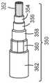
图2A和图2B是根据本公开内容的各种技术的被配置成制备用于安装至电网的电缆350的电缆制备装置50的概念图。电缆350可以是图1A和图1B中所示的电缆32的示例。2A and 2B are conceptual diagrams of a
在图2A的示例中,电缆350包括多个同心(例如,圆柱形)层,例如中心导体352、导体屏蔽354、绝缘356、绝缘屏蔽358、护罩360(也称为护层360)和护套362。然而,在一些示例中,电缆350可以包括更多或更少的层。应当理解,电缆350的层不一定按比例绘制。电缆350可以被配置用于AC和/或DC电力传输。In the example of FIG. 2A ,
作为几个示例电压,电缆350可以传输11kV、33kV、66kV、360kV的电压。在一些情况下,在电力源与变电站之间传输电力的电缆350可以传输360kV或更高的电压,这可以被认为是“传输级电压”。在一些示例中,电缆350传输33kV与360kV之间的电压,例如66kV或33kV,这可以被认为是“二次传输级电压”,并且可以从电力源向终端用户或客户(例如,使用相对大量电力的客户)提供电力。作为另一示例,在配电变电站与配电变压器之间传输电力的电缆350可以传输小于33kV的电压,这可以被认为是“配电级电压”。电缆350还可以在配电变电站或配电变压器(例如,垫安装式变压器或柱安装式变压器)与终端用户或客户(例如,家庭和企业)之间传输电力,并且可以传输360伏特与240伏特之间的电压,在这样的电压下,电缆350可以被称为“二次配电线”。
中心导体352包括导电材料,例如铜或铝。在一些示例中,中心导体352包括单个实心导体或多个绞合导体。中心导体352的直径或厚度基于电缆350被设计成传输或传导的电流。也就是说,中心导体352的横截面面积基于电缆350被设计成传输的电流。例如,中心导体352可以被配置成传输1000安培或更大的电流。
导体屏蔽354可以包括半导电聚合物,例如炭黑负载的聚合物。半导电聚合物可以具有在约5欧姆-厘米至约100欧姆-厘米范围内的体积电阻率。导体屏蔽354可以物理且电气地耦接至中心导体352。在图2的示例中,导体屏蔽354布置在中心导体352与绝缘356之间。导体屏蔽354可以在中心导体352的外部周围提供连续的导电表面,这可以减少或消除可能以其他方式由中心导体352产生的火花。
在一些示例中,绝缘356包括聚乙烯,例如交联聚乙烯(其可以被缩写为PEX、XPE或XLPE)或乙丙橡胶(其可以被缩写为EPR)。绝缘356的直径或厚度基于电缆350被设计成传输或传导的电压。In some examples,
绝缘屏蔽358可以包括类似于导体屏蔽354的半导电聚合物。绝缘屏蔽358布置在绝缘356与护罩360之间。绝缘屏蔽358可以耦接至绝缘356。在一些示例中,绝缘屏蔽358电耦接至护罩360。Insulating
护罩360可以包括导电材料,例如金属箔或薄膜或线。在一些示例中,护罩360可以被称为“接地导体”。
护套362——也称为“外护套”——是电缆350的外层。护套362可以是塑料或橡胶聚合物,例如聚氯乙烯(PVC)、聚乙烯(PE)或三元乙丙橡胶(EPDM)。
电缆350可以包括附加层,例如放置在导体绞合线内的可膨胀或阻水材料(例如,绞合线填充物)或在电缆350内的各层之间的可膨胀或阻水材料。
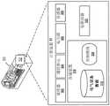
根据本公开内容的各方面,电缆制备装置50包括计算装置52。在一些示例中,计算装置52包括至少一个处理器302、通信单元304、电力源306、一个或更多个传感器308、存储装置310和电驱动器322。图2B示出了电缆制备装置50和计算装置52的一个示例。计算装置52的许多其他示例可以在其他情况下使用并且可以包括在示例计算装置52中包括的部件的子集或可以包括未在图2B的示例中示出的附加部件。According to aspects of the present disclosure, the
计算装置52包括向计算装置52中所示的部件提供电力的一个或更多个电力源306。在一些示例中,电力源306包括提供电力的主电力源和在主电力源不可用(例如,发生故障或以其他方式未提供电力)的情况下提供电力的辅助备用电力源。在一些示例中,电力源306包括电池,例如锂离子电池。
一个或更多个处理器302可以在计算装置52内实现功能和/或执行指令。例如,处理器302可以接收并执行由存储装置310存储的指令。由处理器302执行的这些指令可以使计算装置52在程序执行期间在存储装置310内存储和/或修改信息。处理器302可以执行部件——控制模块320——的指令以执行根据本公开内容的技术的一个或更多个操作。即,控制模块320可以由处理器302操作以执行本文描述的各种功能。One or
计算装置52的一个或更多个通信单元304可以通过发送和/或接收数据来与外部装置通信。例如,计算装置52可以使用通信单元304在诸如蜂窝无线电网络的无线电网络上发送和/或接收无线电信号。通信单元304的示例包括网络接口卡(例如,诸如以太网卡)、光收发器、射频收发器或可以发送和/或接收信息的任何其他类型的装置。通信单元304的其他示例可以包括

计算装置52可以包括一个或更多个传感器308。在一个示例中,传感器308包括一个或更多个位置传感器以检测电缆制备装置50的各部件的位置(例如,工具头、辊或切割工具等的位置)。在另一示例中,传感器308可以包括被配置成测量电缆制备装置50的各部件的速度的一个或更多个速度传感器。
传感器308可以包括一个或更多个成像装置,例如摄像机或条形码扫描器。例如,计算装置52可以包括被配置成在电缆350的层被切割期间和/或之后拍摄电缆350的图像的多个摄像机。
一个或更多个存储装置310可以存储用于由处理器302处理的信息。在一些示例中,存储装置310是临时存储器,意味着存储装置310的主要目的不是长期存储。存储装置310可以被配置为用于信息的短期存储的易失性存储器,并且因此如果去激活则不保留所存储的内容。易失性存储器的示例包括随机存取存储器(RAM)、动态随机存取存储器(DRAM)、静态随机存取存储器(SRAM)以及本领域中已知的其他形式的易失性存储器。One or
在一些示例中,存储装置310还可以包括一个或更多个计算机可读存储介质。存储装置310可以被配置成比易失性存储器存储更大量的信息。存储装置310还可以被配置为用于信息的长期存储的非易失性存储空间,并且在激活/停止周期之后保留信息。非易失性存储器的示例包括固态驱动器(SSD)、磁存储硬盘驱动器(HDD)、闪存、或者电可编程存储器(EPROM)或电可擦除可编程(EEPROM)存储器的形式。存储装置310可以存储与诸如控制模块320的部件相关联的程序指令和/或数据。In some examples,
存储装置310包括电气设备数据储存库312。数据储存库312可以包括关系数据库、多维数据库、映射和散列表或者存储数据的任何数据结构。在一些示例中,电气设备数据储存库312包括装置或设备数据、制造数据、安装数据、客户数据、配电数据等。例如,对于电缆附件34的每个电缆附件,电气设备数据储存库312可以包括标识以下信息的数据:制造日期、安装日期、位置(例如,GPS坐标、街道地址等)、安装了电缆附件的实体、唯一标识符(例如,序列号)、电缆附件的类型等。作为另一示例,电气设备数据储存库312可以包括指示针对各种类型的电缆和/或电缆附件的切割尺寸的数据。The
根据本公开内容的各方面,控制模块320可以由一个或更多个处理器302操作以实现如本文所描述的计算装置52的功能。例如,控制模块320可以输出命令以控制电缆制备装置50的操作。在一些示例中,控制模块320控制电缆制备装置50调节电缆制备装置50的各部件以切割电缆350的各层。在一个示例中,控制模块320输出使电缆制备装置50调节多个辊的深度的命令,这可以使得工具头能够在切割工具切割电缆350的各层时支撑电缆350。According to aspects of the present disclosure,
在一些示例中,控制模块320输出各种命令以控制切割工具的起始位置和切割工具的切割距离(例如,切割深度或削减长度)。例如,控制模块320可以使工具头在电缆350的一个端部处开始切割。在另一示例中,控制模块320可以使工具头距电缆350的端部预定距离开始切割,以产生电缆350的一个或更多个层的保持带。当工具头切割电缆350的层时,保持带可以防止电缆350的一个或更多个层移动或变松。In some examples, the
在一些情况下,控制模块320输出命令以去除电缆350的一个或更多个层。在一个示例中,命令使切割工具穿透至电缆350的特定深度以产生突片。另一命令使切割工具部分地缩回切割工具(例如,缩回至更浅的切割深度),使得切割工具可以去除电缆350的一个或更多个外部层而不切割电缆350的一个或更多个内部层。In some cases,
电驱动器322可以控制供应至电缆制备装置50的各部件的电力的特性。电缆制备装置50的示例部件包括驱动工具头或工具定位驱动器等的马达和/或致动器。电力的示例特性包括电压、电流和/或频率。在一个示例中,电驱动器322向电力转换器输出命令以控制电力的特性。在另一示例中,电驱动器322包括电力转换器以控制电力的特性。The
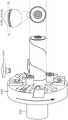
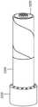
图3A和图3B是示出根据本公开内容的各种技术的示例电缆制备装置1000的概念图。电缆制备装置1000是图1A和图2B的电缆制备装置50的示例。电缆制备装置1000包括计算装置1002。计算装置1002可以被配置成执行参照图1A和图2B所描述的计算装置52的功能。3A and 3B are conceptual diagrams illustrating an example
在一些示例中,电缆制备装置1000包括基部1012A和基部1012B(统称为基部1012)。基部1012经由线性滑轨1014A和线性滑轨1014B(统称为线性滑轨1014)耦接。线性滑轨1014也可以被称为滑轨1014或线性导轨1014。电缆制备装置1000包括耦接至线性滑轨1014的移动基部1016。移动基部1016沿着线性滑轨1014纵向地或线性地移动。In some examples,
电缆制备装置1000包括工具头1018(也称为切割头1018)。工具头1018被配置成围绕电缆32A旋转。工具头1018包括被配置成(例如,当工具头1018围绕电缆32A旋转时)切割电缆32A的至少一层的一个或更多个切割工具。The
计算装置1002可以被配置成控制电缆制备装置1000的一个或更多个部件。在一个示例中,计算装置1002输出使电缆制备装置1000调节多个辊的深度的命令,这可以使得工具头能够在切割工具切割电缆32A的各层时支撑电缆32A。
在一些示例中,计算装置1002输出各种命令以控制切割工具的起始位置和切割工具的切割距离(例如,切割深度或削减长度)。例如,计算装置1002可以输出命令以使工具头1018沿着线性滑轨1014纵向移动以将工具头定位在用于切割电缆32A的起始位置处。在一个示例中,命令使工具头1018在切割电缆32A之前移动至电缆32A的端部。在另一示例中,计算装置1002使工具头1018在切割电缆32A之前移动至位于距电缆32A的端部预定距离的位置。距电缆32A的端部预定距离开始切割可以使得工具头1018能够产生电缆32A的一个或更多个层的保持带。在工具头切割电缆32A的层时,保持带可以防止电缆32A的一个或更多个层移动或变松。In some examples,
在一些情况下,计算装置1002输出命令以去除电缆32A的一个或更多个层。在一个示例中,命令使切割工具穿透至电缆32A的特定深度以产生突片。另一命令使切割工具部分地缩回切割工具(例如,缩回至更浅的切割深度),使得工具头1018的切割工具可以去除电缆32A的一个或更多个外部层而不切割电缆32A的一个或更多个内部层。In some cases,
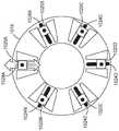
图4A和图4B是示出根据本公开内容的各种技术的示例工具头的细节的概念图。如图4A中所示,工具头1018包括多个槽1024A至1024N(统称为槽1024)和被配置成相对于电缆的中心轴线沿着槽1024径向移动的多个工具安装件1020A至1020N(统称为工具安装件1020)。在一些示例中,工具安装件1020(也称为滑动安装件1020)是弹簧加载的。工具安装件1020可以被配置成保持或耦接一个或更多个工具头部件(例如,辊和/或切割工具)以径向地移动工具头部件。工具头部件的示例包括导辊和切割工具等。4A and 4B are conceptual diagrams illustrating details of an example tool head according to various techniques of this disclosure. As shown in FIG. 4A ,
如图4B中所示,工具头1018包括耦接至滑动安装件1020的多个导辊1054A至1054N(统称为导辊1054或辊1054)。在一些情况下,辊1054还可以被称为定心轴线承1054。在图4B的示例中,辊1054相对于电缆32A的中心轴线径向滑动(例如,朝着电缆32A径向向内和从电缆32A径向向外)。工具头1018可以使辊1054径向向内移动以接触电缆32A,使得辊1054可以在工具头1018绕电缆32A旋转时使电缆32A相对于工具头1018居中。在一些示例中,辊1054沿着相应的工具安装件1020对称地移动。也就是说,工具头1018可以被配置成使得径向移动辊1054A同时移动辊1054B和辊1054C。例如,辊1054可以机械地彼此耦合。As shown in FIG. 4B ,
在图4B的示例中,工具头1018包括切割工具1050A。切割工具的示例包括刀、刀片、锯或被配置成切割电缆32A的一个或更多个层的任何其他类型的工具。例如,可以实现不同的刀片以在电缆32A的一个或更多个层中产生不同类型或不同深度的切口。在一个示例中,切割工具1050A与辊1054中的一个(例如,辊1054B)周向定位成约180度(例如,加或减15度)。以这种方式,当切割工具1050A压靠电缆32A时,辊1054B和切割工具1050A彼此平衡,使得电缆32A保持位于工具头1018的中心或大约位于工具头1018的中心。In the example of FIG. 4B ,
图5是示出根据本公开内容的各种技术的示例工具头的细节的概念图。工具头1018包括多个切割工具1050A至1050N(统称为切割工具1050)。在一个示例中,切割工具1050中的每个切割工具与辊1054中的相应辊周向定位成约180度(例如,加或减15度)。以这种方式,当切割工具压靠电缆时,辊1054和切割工具1050彼此平衡,使得电缆保持位于工具头1018的中心或大约位于工具头1018的中心。5 is a conceptual diagram illustrating details of an example tool head according to various techniques of this disclosure.
在一个示例中,切割工具1050A被配置成切穿电缆32A的金属层,例如图2A中所示的护罩层360。在一些情况下,切割工具1050A被配置成切穿电缆32A的所有层。也就是说,在这样的情况下,切割工具1050A被配置成完全切穿电缆32A(例如,在单次切割中)。In one example, cutting
在另一示例中,切割工具1050B被配置成进行与电缆32的暴露层的外表面基本相切的浅的刮削型切割(例如,以减小暴露层的一部分的厚度)。切割工具1050B可以被配置成刻划绝缘层或绝缘屏蔽(例如,分别如图2A中所示的绝缘356或绝缘屏蔽358)。作为另一示例,切割工具1050B可以被配置成切割金属护罩层(例如,带、箔、线等)。In another example, cutting
在一个示例中,切割工具1050N被配置成切割和去除电缆32A的一个或更多个层。例如,切割工具1050N可以被配置成对护套362、绝缘屏蔽358、绝缘356或其组合执行螺旋切割(也称为螺旋形切割)。In one example, cutting
图6A至图6F是示出用于操作电缆制备装置1000(图3B)的示例工具头的示例技术的概念图。电缆制备装置1000包括工具定位驱动器1026。工具定位驱动器1026可以被配置成调节工具头1018的工具头部件的径向深度(也称为径向位置)。径向深度可以指电缆32A的中心轴线与工具头部件的一部分(例如,切割工具或辊的表面)之间的距离。6A-6F are conceptual diagrams illustrating example techniques for operating an example tool head of cable preparation apparatus 1000 (FIG. 3B). The
如图6A中所示,工具头1018旋转以将工具定位驱动器1026与槽1024中的一个(例如,槽1024D)对准。在图6B的示例中,工具定位驱动器1026延伸入或插入槽1024D中以与工具安装件(例如,工具安装件1020D)接合。在一个示例中,工具安装件1020各自包括被配置成接收工具定位驱动器1026的凹部(例如,槽、梅花形套筒、六角套筒或任何其他类型的凹部)。在一些情况下,工具定位驱动器1026经由螺线管、凸轮轴线、气动活塞或被配置成调节工具定位驱动器1026的径向深度的其他机构来致动(例如,插入或缩回)。As shown in FIG. 6A ,
在一些示例中,例如图6C的示例,工具定位驱动器1026旋转以调节工具安装件1020D的径向深度,并且因此调节附接至工具安装件1020D的辊1054B。例如,工具定位驱动器1026可以旋转(例如,逆时针)以将辊1054B推向电缆32。在一个示例中,辊1054被配置成对称地移动。也就是说,工具定位驱动器1026可以通过调节附接至辊1054B的工具安装件1020D的深度来调节辊1054中的每个辊的径向深度。在一个示例中,工具定位驱动器1026可以将辊1054推动至预定径向深度(例如,基于电缆32A的类型)。在另一示例中,工具定位驱动器1026可以推动辊1054直到针对辊1054或工具定位驱动器1026的阻力或力满足(例如,大于或等于)阈值阻力或力,或者直到阻力或力在特定的阻力或力范围内。在一个示例中,计算装置1002确定辊1054是否处于适当的径向深度以将电缆32A保持在适当的切割位置(例如,在工具头1018内居中)。例如,计算装置1002可以接收指示由辊1054或工具定位驱动器1026经受的机械阻力或力的传感器数据,并且确定辊1054是否处于适当的径向深度。在另一示例中,计算装置1002可以接收指示辊1054的径向位置的传感器数据以确定辊1054是否处于适当的径向深度。In some examples, such as the example of FIG. 6C , the
如图6D中所示,一旦辊1054处于适当的深度(例如,处于预定深度,或者当阻力或力满足阈值阻力或力时),工具定位驱动器1026就可以从槽1024D中撤回或抽出。As shown in FIG. 6D , once the roller 1054 is at the proper depth (eg, at a predetermined depth, or when the resistance or force meets a threshold resistance or force), the
如由图6E所示,在从槽1024D中撤回工具定位驱动器1026之后,工具头1018可以旋转以使工具定位驱动器1026与另一槽(例如,槽1024E)对准。工具定位驱动器1026可以在槽1024E与工具定位驱动器1026对准时插入槽1024E中。As shown by FIG. 6E , after
如图6F中所示,工具定位驱动器1026可以调节工具安装件1020E和耦接至工具安装件1020E的切割工具1050N的径向深度。例如,工具定位驱动器1026可以接合工具安装件1020E的凹部并且可以旋转以调节工具安装件1020E的径向深度(例如,目标切割深度)。例如,工具定位驱动器1026可以将工具安装件1020E推动至预定径向切割深度(例如,基于电缆32A的类型),或者直到针对切割工具1050N或工具定位驱动器1026的阻力或力满足(例如,大于或等于)阈值阻力或力。在一个示例中,计算装置1002确定切割工具1050N的径向深度是否正确或是适当的深度。例如,计算装置1002可以基于传感器数据来确定切割工具1050N是否处于适当的切割深度。例如,计算装置1002可以基于指示由切割工具1050N或工具定位驱动器1026经受的机械阻力的传感器数据来确定切割工具1050N是否处于适当的切割深度(也称为目标切割深度)。在另一情况下,计算装置1002基于指示切割工具1050N的电气特性(例如,切割工具1050N的电阻或电容)的传感器数据来确定切割工具1050N是否处于适当的切割深度。例如,切割工具1050N的电气特性可以在切割工具1050N切穿电缆32A的护套层并接近和/或接触护罩层时改变。作为又一示例,计算装置1002可以基于由图像传感器(例如,摄像机)生成的图像、超声传感器或来自任何其他传感器的数据来确定切割工具1050N是否处于适当的切割深度。As shown in FIG. 6F , the
在一些示例中,电缆制备装置1000包括被配置成相对于电缆32A的纵向轴线径向移动的一个或更多个夹具。所述一个或更多个夹具可以被配置成限制电缆32A的运动(例如,旋转的或纵向的)。在一些示例中,夹具可以使得刀片能够相对于电缆的轴线以一定角度倾斜(例如,以螺旋切割电缆的层)以进行基本上垂直于或正交于电缆轴线的切割。In some examples,
图7是示出根据本公开内容的各种技术的示例电缆的细节的概念图。在一些示例中,电缆800A至电缆800F(统称为电缆800)中的每个电缆是不同类型的电缆。图7示出了在通过电缆制备装置(例如,图3B的电缆制备装置1000)制备电缆800的各个阶段期间的示例电缆800。即,电缆800中的每个电缆的各层的各部分已经被去除以将电缆800中的每个电缆制备成耦接至电缆附件例如电缆接头或终端。7 is a conceptual diagram illustrating details of an example cable according to various techniques of this disclosure. In some examples, each of
图8是示出根据本公开内容的各种技术的使用电缆制备装置制备示例电缆950的示例技术的细节的概念图。参照图3的电缆制备装置1000描述图8。然而,可以使用其他电缆制备装置来执行参照图8所描述的功能。FIG. 8 is a conceptual diagram illustrating details of an example technique for preparing an
在一些示例中,电缆制备装置1000切穿电缆950的每个层(902)。在一个示例中,电缆制备装置1000的工具头1018的切割工具1050A被配置成(例如,周向地)切穿整个电缆950,这可以为电缆950提供相对干净的边缘(例如,相对于具有磨损的或用旧的端部的电缆)。In some examples,
在图8的示例中,工具头1018产生护套开口966并且产生保持带964(904)。例如,工具头1018可以沿着滑轨1014纵向移动至起始位置,在工具头1018将该起始位置处开始切割电缆950以产生护套开口966。纵向起始位置可以位于纵向参考位置(例如,电缆950的端部)处或距纵向参考位置预定距离处。纵向参考位置还可以被称为零点或零位置。在一些示例中,预定距离基于电缆950的一个或更多个层的预定义的保持带距离(RBD)或目标削减长度。工具头1018可以响应于接收来自计算装置1002的命令而移动至纵向起始位置。如图8中所示,工具头1018纵向移动至位于距电缆950的端部保持带距离的纵向起始位置。在一些示例中,响应于工具头1018移动至纵向起始位置,切割工具1050中的一个(例如,切割工具1050A或切割工具1050B)朝向电缆950径向移动并且切割至径向目标切割深度以切穿电缆950的至少护套层962以产生护套开口966。例如,可以通过使工具头1018绕电缆950旋转来由工具头1018穿过护套层962切割径向距离。以这种方式,在一个示例中,工具头1018可以切穿电缆的护套层962以将保持带964与其余护套层962分离。In the example of FIG. 8 ,
在一些示例中,在将保持带964与护套层962的剩余部分分离之后,工具头1018切穿护套层962的内部部分968(也称为内部区域)(906)。护套层962的内部部分可以由纵向起始位置和由针对护套层962的目标削减长度限定的位置来限定。在一些示例中,工具头1018沿滑轨1004纵向移动至目标削减长度,而切割工具1050中的一个定位在目标切割深度处以切割护套层962。例如,工具头1018可以利用切割工具1050N从电缆950去除护套层962。In some examples,
在一个示例中,用于切割电缆的一个层(例如,护套层962)的切割工具的切割角度可以比用于切割另一层(例如,绝缘层)的切割工具的切割角度更陡峭。在一些示例中,切割工具1050N可以包括相对低的切割角度。在切割工具1050N包括低切割角度的示例中,切割工具1050N的刀片与电缆950的表面之间的切割角度可以是约20度(例如,加或减5度)。相对低的角度可以提高切割工具1050N去除电缆950的一个或更多个绝缘层的能力。在另一示例中,切割工具1050N包括相对高的切割角度。在切割工具1050N包括高切割角度的示例中,切割工具1050N的刀片与电缆950的表面之间的切割角度可以是约60度(例如,加或减20度)。以这种方式,相对高的切割角度可以提高切割工具1050N去除护套层962的能力。In one example, the cutting angle of the cutting tool used to cut one layer of the cable (eg, jacket layer 962 ) may be steeper than the cutting angle of the cutting tool used to cut another layer (eg, insulation layer). In some examples, cutting
在一些示例中,工具定位驱动器1026可以调节切割工具1050A(或1050B)的径向距离以将切割工具1050A(或1050B)从电缆950中抽出,并且可以将切割工具1050N定位在目标切割深度处。在一些示例中,电缆制备装置1000通过在切割护套层962的同时纵向移动工具头1018而不旋转工具头1018来执行直线切割。在另一示例中,电缆制备装置1000通过纵向移动工具头1018并且同时围绕或绕电缆950旋转来执行螺旋切割。在一个示例中,在到达由目标削减长度限定的位置时,切割工具1050中的一个执行周向切割以去除护套层962的内部部分。例如,工具头1018可以保持纵向固定在目标削减长度处,并且切割工具1050N可以保持在目标切割深度处同时工具头1018围绕电缆950旋转以通过去除护套层962的内部部分来终止对护套层962的切割。In some examples,
电缆制备装置1000去除保持带964(908)。在一个示例中,电缆制备装置1000通过在去除护套层962的内部部分之后切割保持带964来去除保持带964(908)。例如,工具头1018可以朝向起始位置纵向移动,并且切割工具1050中的一个可以随着工具头1018朝向电缆950的端部纵向移动而切穿护套层962以去除保持带964。在一些示例中,电缆制备装置1000的用户可以去除保持带964。去除护套层962的内部部分同时保留保持带964可以使得电缆制备装置1000能够去除护套层962的内部部分并且可选地去除附加层(例如,护罩960)同时固定各层的端部。固定各层的端部可以防止电缆950的层在切割和去除电缆950的层时磨损,这可以简化电缆950的层的去除并且潜在地减少或消除在制备电缆950的层时导致的电缆中的缺损。The
在一些示例中,电缆制备装置1000可以折叠护罩960或导体屏蔽354(910)。例如,电缆制备装置1000可以将护罩960折叠在护套962的剩余部分的顶部上。在另一示例中,电缆制备装置1000的用户可以折叠护罩960。In some examples,
图9A至图9D是示出根据本公开内容的各种技术的利用电缆制备装置制备示例电缆的示例技术的细节的概念图。参照图3B的电缆制备装置1000描述图9A至图9D,然而,可以使用其他电缆制备装置来执行所描述的功能。9A-9D are conceptual diagrams illustrating details of an example technique for preparing an example cable using a cable preparation device according to various techniques of this disclosure. Figures 9A-9D are described with reference to the
工具头1018产生护套开口1466并且产生保持带1464。例如,工具头1018可以沿着滑轨1014纵向移动至起始位置,工具头1018将在该起始位置处开始切割电缆1550以产生护套开口1466。响应于工具头1018移动至纵向起始位置,切割工具1050中的一个(例如,切割工具1050B)朝向电缆1550径向移动(1402)。切割工具1052B切割至目标切割深度以切穿电缆1550的至少护套层1462(1404)。工具头1018绕电缆1550旋转(1406)以周向地切穿护套层1462以产生保持带1464。
在一些示例中,电缆制备装置1000在产生保持带1564之后去除护套层1562的内部部分1568。电缆制备装置1000可以利用一个切割工具(例如,切割工具1050B)来产生保持带1564,并且利用不同的切割工具(例如,切割工具1050N)来去除护套层1562的内部部分。在一个示例中,在产生保持带1564之后,电缆制备装置1000可以从电缆1550向外调节切割工具1050B的径向深度。电缆制备装置1000可以在向外调节切割工具1050B的深度之后朝向电缆1550调节切割工具1050N的径向深度。例如,电缆制备装置1000可以将工具安装件1020D和耦接至工具安装件1020D的切割工具1050B的径向深度调节至预定的径向切割深度(例如,基于电缆1550的类型),或者直到针对切割工具1050B或工具定位驱动器1026的阻力或力满足(例如,大于或等于)阈值阻力或力。In some examples,
在一些示例中,切割工具1050N是弹簧加载的。在一个示例中,切割工具1050N或工具安装件1020N包括弹簧组件1067,该弹簧组件1067被配置成使切割工具1050N沿径向方向移动。例如,切割工具1050N可以经由弹簧1068安装至工具安装件1020N。在这样的示例中,电缆制备装置1000可以压缩弹簧1068,这可以使切割工具1050N至少部分地切穿护套层1062至第一目标切割深度。In some examples, cutting
当切割刀具1050N处于第一目标切割深度时,工具头1018可以旋转部分旋转。使工具头1018旋转部分旋转可以使得切割工具1050N能够产生突片1570。The
图10A至图10C是示出根据本公开内容的各种技术的使用电缆制备装置制备示例电缆的示例技术的细节的概念图。参照图3B的电缆制备装置1000描述图10A至图10C,然而,可以使用其他电缆制备装置来执行所描述的功能。10A-10C are conceptual diagrams illustrating details of an example technique for preparing an example cable using a cable preparation device in accordance with various techniques of this disclosure. Figures 10A-10C are described with reference to the
在一些示例中,在产生突片1670之后,电缆制备装置1000可以去除护套层1662的内部部分。在一些示例中,电缆制备装置以与用于产生突片1670的切割深度相同的切割深度执行径向或纵向切割。也就是说,在一个示例中,切割工具1050N在切穿护套层1662时保持在第一目标切割深度处以去除护套层1662的内部部分。In some examples, after
在另一示例中,电缆制备装置1000将切割工具1050N的深度调节至比第一目标切割深度浅的第二目标切割深度(1602)。也就是说,电缆制备装置1000可以将切割工具1050N缩回至第二目标切割深度。第二目标切割深度可以在第一目标切割深度的阈值深度内,这可以使得切割工具1050N能够保持在护套层1662下(例如,不干扰诸如护罩层的相邻层)。将切割工具1050N缩回至第二目标切割深度可以将突片1670从与护套层1662相邻的另一层(例如,护罩层)抬起。以这种方式,电缆制备装置可以以第二目标切割深度执行螺旋切割,以从电缆1650抬起并去除护套层1662的内部部分。在一些示例中,第二目标切割深度也被称为护套去除深度或护套去除位置。In another example, the
工具头1018可以去除护套层1662的内部部分(1604)。在一个示例中,在第二目标切割时,工具头1018与切割工具1050N一起旋转,同时沿着滑轨1014纵向移动。例如,工具头1018可以从纵向起始位置纵向移动至由针对护套层1662的目标削减长度限定的位置。在一个示例中,在到达由目标削减长度限定的位置时,切割工具1050中的一个执行周向切割以去除护套层1662的内部部分。例如,工具头1018可以通过围绕电缆1650旋转来执行周向切割,以终止对护套层1662的切割并去除护套层1662的内部部分。
图11是示出根据本公开内容的各种技术的使用电缆制备装置制备示例电缆的示例技术的细节的概念图。参照图3B的电缆制备装置1000描述图11,然而,可以使用其他电缆制备装置来执行所描述的功能。11 is a conceptual diagram illustrating details of an example technique for preparing an example cable using a cable preparation device in accordance with various techniques of this disclosure. Figure 11 is described with reference to the
电缆制备装置1000可以去除护套层2662和护罩2660的一部分。响应于折叠护罩2660,电缆制备装置可以去除绝缘屏蔽层、绝缘层或两者。例如,电缆制备装置1000可以经由螺旋切割或纵向切割来切割或刻划绝缘屏蔽2658的一部分(2602)。电缆制备装置1000可以周向切割绝缘屏蔽2658(2604)以去除绝缘屏蔽2658的一部分。在去除绝缘屏蔽2658之后,电缆制备装置1000可以去除绝缘2656的一部分(2606)。例如,电缆制备装置1000可以经由螺旋切割或纵向切割来切割或刻划绝缘2656。电缆制备装置1000可以在刻划绝缘2656之后执行周向切割以去除绝缘2656的一部分。The
图12是示出根据本公开内容的各种技术的耦接两个电缆1202和1204的示例电缆接头1200的细节的概念图。在通常的接头安装中,靠近电缆端部的一些绝缘1206位于接头电极1208下方,该接头电极1208处于与中心导体1210和连接器1212相同的电势。虽然该区域外的绝缘1206的表面损坏可能导致空气空隙和在通电时的局部放电,但是由于相等的电势,该区域中的表面缺损将不会引起局部放电。可分离连接器通常还具有电极区域,并且因此可以容忍某些局部区域中的绝缘损坏,而终端在电缆端部附近可以具有较低的电场强度,对局部区域中的绝缘损坏具有一定的容限。12 is a conceptual diagram illustrating details of an example cable joint 1200 coupling two
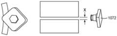
图13A至图13C是示出根据本公开内容的各种技术的使用具有摄像机的电缆制备装置制备示例电缆的示例技术的细节的概念图。参照图3的电缆制备装置1000描述图13A至图13C,然而,可以使用其他电缆制备装置来执行所描述的功能。13A-13C are conceptual diagrams illustrating details of an example technique for preparing an example cable using a cable preparation device with a camera, according to various techniques of this disclosure. Figures 13A-13C are described with reference to the
电缆制备装置1000可以包括被配置成在切割电缆3050期间和/或之后生成电缆3050的图像的一个或更多个摄像机1072。摄像机1072可以生成电缆3050的横截面、电缆3050的纵向表面或两者的一个或更多个图像。
计算装置1002可以基于由摄像机1072生成的一个或更多个图像来确定针对电缆3050的一个或更多个层的目标切割深度。在一些示例中,计算装置1002基于电缆3050的各层的颜色的对比度来确定目标切割深度。例如,第一层(例如,绝缘3056)可以基本上是一种颜色(例如,黑色),并且邻接层(例如,绝缘屏蔽3058)可以基本上是与第一颜色具有相对大对比度的另一颜色(例如,白色)。在这样的示例中,在颜色的对比度可以指示切割工具1050B已经切穿电缆的整个层。计算装置1002可以响应于检测由摄像机1072生成的一个或更多个图像中的颜色方面的对比度来确定切割工具1050中的一个(例如,切割工具1050B)的实际切割深度。在一些示例中,计算装置1002确定针对一个或更多个层的目标切割深度(也称为最优刻划深度)等于在图像中检测到颜色方面的对比度时的实际切割深度。
在一个示例中,计算装置1002可以基于与多个切割相关联的多个图像来确定特定层(例如,绝缘屏蔽358)的目标切割深度。例如,电缆制备装置1000可以在连续更深的切口(3001)处多次将切割工具1050N延伸至特定层中,并且摄像机1072可以针对切口中的每个切口生成一个或更多个图像。在这样的示例中,计算装置1002可以确定目标切割深度等于与在图像中检测到第一层(例如,绝缘屏蔽3058)与第二层(例如,绝缘3056)之间的颜色对比度的图像相关联的切割工具1050N的实际切割深度。In one example,
在另一示例中,计算装置1002基于与单个切割相关联的一个或更多个图像来确定针对特定层的目标切割深度。例如,电缆制备装置1000可以将切割工具1050N以相对深的深度(例如,与多个连续更深的切口中的第一切口中的一个相比)延伸至特定层中。在执行切割之后,摄像机1072可以生成沿x方向(3002)电缆3050的第一图像和沿y方向(3003)电缆3050的第二图像。计算装置1002可以基于第一图像、第二图像、切割工具1050N的尺寸和角度、特定层的宽度、电缆3050的曲率或其组合来确定目标切割深度。In another example,
图14是示出根据本公开内容的各种技术的使用具有摄像机的电缆制备装置制备示例电缆的示例技术的细节的概念图。参照图3的电缆制备装置1000描述图14,然而,可以使用其他电缆制备装置来执行所描述的功能。14 is a conceptual diagram illustrating details of an example technique for preparing an example cable using a cable preparation device with a camera in accordance with various techniques of this disclosure. Figure 14 is described with reference to the
电缆制备装置1000可以包括被配置成在切割电缆3150期间和/或之后生成电缆3150的图像的一个或更多个摄像机1072。摄像机1072可以生成电缆3150的横截面、电缆3150的纵向表面或两者的一个或更多个图像。在一些示例中,摄像机1072耦接至工具头1018,使得摄像机1072随着工具头1018旋转而围绕电缆3150旋转。
摄像机1072可以生成由切割工具1050执行的一次或更多次切割的电缆3150的图像。例如,摄像机1072可以在切割工具1050执行电缆3150的一个或更多个切割(例如,周向切割和/或螺旋切割)之前、期间和/或之后生成电缆3150的图像。
图15是示出根据本公开内容的各种技术的示例制备的电缆的概念图。电缆制备装置1000可以执行穿过绝缘屏蔽3258的纵向切割以帮助去除绝缘屏蔽3258的一部分。电缆制备装置1000可以在相对于螺旋切割或螺旋刻划与绝缘3256的端部或绝缘屏蔽3258的端部的相交处的任何位置处执行纵向切割。在一个示例中,电缆制备装置1000执行纵向切割,其中螺旋切割与绝缘3256的端部相交。FIG. 15 is a conceptual diagram illustrating a cable prepared according to an example of various techniques of the present disclosure.
在一些示例中,电缆制备装置1000在损伤容限区中执行纵向切割。在这样的示例中,电缆制备装置1000可以执行穿过绝缘屏蔽(例如,进入绝缘)的相对深的切割,这可以使得电缆制备装置1000能够更好地启动剥离处理。In some examples, the
在一些示例中,电缆制备装置1000以类似于去除护套层的方式去除电缆的绝缘屏蔽的内部部分。例如,电缆制备装置1000可以调节工具安装件1020E和耦接至工具安装件1020N的切割工具1050N的径向深度。在一个实例中,电缆制备装置1000将径向深度调节至预定的径向切割深度(例如,基于电缆的类型),或者直到针对切割工具1050N或工具定位驱动器1026的阻力或力满足(例如,大于或等于)阈值阻力或力。In some examples, the
在一些情况下,电缆制备装置1000压缩弹簧1068,这可以使切割工具1050N至少部分地切穿绝缘屏蔽至第一目标切割深度。In some cases,
当切割工具1050N处于第一目标切割深度时,工具头1018可以旋转部分旋转。在一些示例中,第一目标切割深度延伸至诸如绝缘的相邻层中。使工具头1018旋转部分旋转可以使得切割工具1050N能够产生突片。
在一些示例中,在产生突片之后,电缆制备装置1000可以以类似于去除护套层的方式去除绝缘屏蔽的内部部分。在一些示例中,电缆制备装置以与用于产生突片的切割深度相同的切割深度执行径向或纵向切割。也就是说,在一个示例中,切割工具1050N在切穿护套层时保持在第一目标切割深度处以去除护套层的内部部分。In some examples, after creating the tabs, the
在另一示例中,电缆制备装置1000将切割工具1050N的深度调节至比第一目标切割深度浅的第二目标切割深度。也就是说,电缆制备装置1000可以将切割工具1050N缩回至第二目标切割深度。第二目标切割深度可以在第一目标切割深度的阈值深度内,这可以使得切割工具1050N能够保持在绝缘屏蔽下。将切割工具1050N缩回至第二目标切割深度可以将突片从与绝缘屏蔽相邻的另一层(例如,绝缘层)抬起。以这种方式,电缆制备装置可以以第二目标切割深度执行螺旋切割,以从电缆抬起和去除绝缘屏蔽的内部部分。在一些示例中,第二目标切割深度也被称为绝缘屏蔽去除深度或绝缘屏蔽去除位置。In another example, the
工具头1018可以去除护套层的内部部分。在一个示例中,在第二目标切割时,工具头1018与切割工具1050N一起旋转,同时沿着滑轨1014纵向移动。例如,工具头1018可以纵向移动至由针对绝缘屏蔽的目标削减长度限定的位置。在一个示例中,在到达由目标削减长度限定的位置后,切割工具1050中的一个执行周向切割以去除绝缘屏蔽的内部部分。例如,工具头1018可以通过围绕电缆旋转来执行周向切割,以终止对绝缘屏蔽3458的切割并去除绝缘屏蔽的内部部分。The
在一些示例中,切割工具1050中的一个(例如,切割工具1050B)可以在电缆的绝缘屏蔽和/或绝缘上执行刮削操作。刮削绝缘可以使得电缆制备装置1000能够使绝缘的表面平滑。刮削绝缘屏蔽可以使得电缆制备装置1000能够减少或消除从绝缘屏蔽至绝缘的过渡中的缺损。In some examples, one of cutting tools 1050 (eg, cutting
图16是示出根据本公开内容的各种技术的由示例电缆制备装置执行的示例操作的流程图。参照图3的电缆制备装置1000描述图16,然而,可以使用其他电缆制备装置来执行所描述的功能。电缆可以是图2A的电缆350或图1A和图1B的电缆32的示例,然而,本公开内容的技术也可以应用于其他电缆。16 is a flowchart illustrating example operations performed by an example cable preparation device in accordance with various techniques of this disclosure. Figure 16 is described with reference to the
电缆制备装置1000可以通过切穿电缆32A的一个或更多个层来产生保持带。例如,电缆制备装置1000将工具头1018定位在距电缆32的端部一定距离的纵向起始位置处(3602)。电缆制备装置1000执行穿过电缆32A的至少一个层的周向切割以使用电缆32A的护套层产生保持带(3604)。例如,电缆制备装置1000可以通过在使工具头1018沿纵向方向保持静止的情况下使工具头绕电缆32A旋转来执行周向切割。The
响应于产生保持带,电缆制备装置1000可以去除纵向起始位置与由与护套层相关联的目标削减长度限定的纵向位置之间的护套层的内部部分。在一个示例中,电缆制备装置1000将切割工具1050中的一个(例如,用于执行周向切割的同一切割工具或不同的切割工具)的深度设置为第一目标切割深度(3606)。In response to creating the retention tape, the
电缆制备装置1000通过使工具头1018在切割工具处于第一目标切割深度的情况下旋转部分旋转来在护套层中产生突片(3608)。在一些示例中,响应于在护套层中产生突片,电缆制备装置1000将切割工具缩回至第二目标切割深度(3610)。第二目标切割深度可以比第一目标切割深度浅,这可以将护套层的突片部分从相邻层(例如,护罩层)抬起。The
在一个示例中,电缆制备装置1000利用切割工具以第二目标切割深度在护套层上执行螺旋切割(3612)。例如,电缆制备装置1000可以通过旋转工具头1018同时沿着滑轨1014纵向移动工具头1018来沿着电缆32A的内部部分执行螺旋切割。In one example, the
在一些示例中,电缆制备装置1000执行周向切割以去除电缆32A的内部部分(3614)。电缆制备装置1000可以使用用于执行螺旋切割的同一切割工具或切割工具1050中的另一个来执行周向切割。In some examples,
图17A和图17B是示出根据本公开内容的各种技术的使用电缆制备装置的电缆1700中的示例突片1702的概念图。参照图3的电缆制备装置1000描述图17A和图17B,然而,可以使用其他电缆制备装置来执行所描述的功能。17A and 17B are conceptual diagrams illustrating
电缆制备装置1000可以在层(例如,绝缘屏蔽1704)中产生突片1702。在一个示例中,电缆制备装置利用单个切割工具来产生突片。例如,电缆制备装置1000在绝缘屏蔽的端部处执行纵向切割,并且在执行纵向切割之后执行螺旋切割。执行纵向切割然后执行螺旋切割可以在绝缘屏蔽层的端部处产生突片。电缆制备装置1000可以在执行螺旋切割之后执行周向切割。在层的端部处执行纵向切割然后执行螺旋切割可以产生突片,这可以促进绝缘屏蔽的剥离(例如,自动地或手动地)。电缆制备装置1000可以利用单个切割工具执行纵向切割、螺旋切割和周向切割。与可以利用两个不同的切割工具执行不同的切割的一些技术相比,通过以该方式执行一系列的切割,电缆制备装置1000可以利用单个切割工具1050来切割或刻划绝缘屏蔽。
除非另有指示,否则在说明书和权利要求中使用的表示特征尺寸、数量和物理性质的所有数字应被理解为在所有情况下由术语“约”修饰。因此,除非有相反的指示,否则在前述说明书和所附权利要求中阐述的数值参数是近似值,其可以根据由本领域技术人员利用本文所公开的教导寻求获得的期望性质而变化。Unless otherwise indicated, all numbers expressing characteristic dimensions, quantities and physical properties used in the specification and claims are to be understood as being modified in all instances by the term "about". Accordingly, unless indicated to the contrary, the numerical parameters set forth in the foregoing specification and attached claims are approximations that can vary depending upon the desired properties sought to be obtained by those skilled in the art utilizing the teachings disclosed herein.
如在本说明书和所附权利要求中所使用的,除非内容另有明确指示,否则单数形式“一”、“一个”和“该”包括具有多个指示物的实施方式。如在本说明书和所附权利要求中所使用的,除非内容另有明确指示,否则术语“或”通常以其包括“和/或”的意义使用。As used in this specification and the appended claims, the singular forms "a," "an," and "the" include plural referents unless the content clearly dictates otherwise. As used in this specification and the appended claims, the term "or" is generally employed in its sense including "and/or" unless the content clearly dictates otherwise.
空间相关术语,包括但不限于“接近”、“远端”、“下部”、“上部”、“下方”、“下面”、“上面”和“在顶上”,如果在本文中使用,用于易于描述一个元件与另一元件的空间关系。除了在附图中描绘和本文描述的特定取向之外,这样的空间相关术语还包括使用或操作中的装置的不同取向。例如,如果在附图中描绘的对象被倒置或翻转,则先前描述为在其他元件下面或下方的部分则将在所述其他元件上面或顶上。Spatially relative terms, including but not limited to "near", "distal", "lower", "upper", "below", "below", "above" and "on top", if used herein, are replaced by for ease of describing the spatial relationship of one element to another. Such spatially relative terms encompass different orientations of the device in use or operation in addition to the specific orientations depicted in the figures and described herein. For example, if an object depicted in the figures is turned upside down or turned over, parts previously described as being below or below other elements would then be on top of or on top of the other elements.
如本文所使用的,当一个元件、部件或层例如被描述为与另一元件、部件或层形成“重合界面”或者被描述为“在其上”、“连接至其”、“与其耦接”、“堆叠在其上”或“与其接触”时,所述一个元件、部件或层可以直接在另一元件、部件或层上,或直接连接至其、直接与其耦合、直接堆叠在其上、与其直接接触,或者例如中间元件、部件或层可以在特定的元件、部件或层上,或者与该特定的元件、部件或层连接、耦接或接触。当一个元件、部件或层例如被称为“直接在另一元件上”、“直接连接至另一元件”、“直接与另一元件耦接”或“直接与另一元件接触”时,不存在例如中间元件、部件或层。本公开内容的技术可以在多种计算机装置中实现,例如服务器、膝上型计算机、桌上型计算机、笔记本计算机、平板计算机、手持计算机、智能电话等。任何部件、模块或单元已经被描述以强调功能方面并且不一定需要由不同的硬件单元来实现。本文描述的技术还可以在硬件、软件、固件或其任何组合中实现。被描述为模块、单元或部件的任何特征可以在集成逻辑装置中一起实现或者单独实现为分立的但可互操作的逻辑装置。在一些情况下,各种特征可以被实现为集成电路装置,例如集成电路芯片或芯片组。此外,虽然在整个说明书中已经描述了许多不同的模块,这些模块中的许多模块执行唯一的功能,但是所有模块的所有功能可以被组合到单个模块中,或者甚至被分到其他附加模块中。本文描述的模块仅是示例性的,并且为了更易于理解已经如此描述。As used herein, when an element, component or layer is described, for example, as forming a "coincident interface" with another element, component or layer or as being "on", "connected to", "coupled to", ", "stacked on" or "in contact with", said one element, part or layer may be directly on another element, part or layer, or be directly connected to, directly coupled to, or directly stacked on another element, part or layer , in direct contact therewith, or for example, an intermediate element, component or layer may be on, or connected, coupled or in contact with, a particular element, component or layer. When an element, component or layer is referred to as being "directly on", "directly connected to", "directly coupled to" or "directly in contact with" another element, it does not There are eg intermediate elements, components or layers. The techniques of this disclosure can be implemented in a variety of computing devices, such as servers, laptops, desktops, notebooks, tablets, handheld computers, smart phones, and the like. Any components, modules or units have been described to emphasize functional aspects and do not necessarily require realization by different hardware units. The techniques described herein may also be implemented in hardware, software, firmware, or any combination thereof. Any features described as modules, units or components may be implemented together in an integrated logic device or separately as discrete but interoperable logic devices. In some cases, various features may be implemented as an integrated circuit device, such as an integrated circuit chip or chipset. Furthermore, while many different modules have been described throughout this specification, many of which perform unique functions, all functions of all modules may be combined into a single module, or even divided into other additional modules. The modules described herein are exemplary only and have been so described for easier understanding.
如果以软件实现,则这些技术可以至少部分地通过包括指令的计算机可读介质来实现,所述指令在处理器中执行时执行上述方法中的一个或更多个。计算机可读介质可以包括有形的计算机可读存储介质并且可以形成计算机程序产品的一部分,该计算机程序产品可以包括包装材料。计算机可读存储介质可以包括随机存取存储器(RAM)例如同步动态随机存取存储器(SDRAM)、只读存储器(ROM)、非易失性随机存取存储器(NVRAM)、电可擦除可编程只读存储器(EEPROM)、闪存、磁性数据存储介质或光学数据存储介质等。计算机可读存储介质还可以包括非易失性存储装置,例如硬盘、磁带、光盘(CD)、数字通用盘(DVD)、蓝光光盘、全息数据存储介质,或者其他非易失性存储装置。If implemented in software, the techniques may be implemented at least in part by a computer-readable medium comprising instructions that, when executed in a processor, perform one or more of the methods described above. The computer readable medium may comprise tangible computer readable storage media and may form part of a computer program product, which may include packaging materials. The computer readable storage medium may include random access memory (RAM) such as synchronous dynamic random access memory (SDRAM), read only memory (ROM), nonvolatile random access memory (NVRAM), electrically erasable programmable Read only memory (EEPROM), flash memory, magnetic data storage media or optical data storage media, etc. Computer-readable storage media may also include non-volatile storage devices such as hard disks, magnetic tape, compact discs (CDs), digital versatile discs (DVDs), Blu-ray discs, holographic data storage media, or other non-volatile storage devices.
如本文所使用的术语“处理器”可以指任何前述结构或适合于实现本文描述的技术的任何其他结构。另外,在一些方面,可以在被配置用于执行本公开内容的技术的专用软件模块或硬件模块内提供本文描述的功能。即使以软件实现,这些技术也可以使用诸如处理器的硬件来执行软件,以及使用存储器来存储软件。在任何这种情况下,本文描述的计算机可以定义能够执行本文描述的特定功能的特定机器。此外,这些技术可以在一个或更多个电路或逻辑元件中完全实现,该电路或逻辑元件也可以被视为处理器。The term "processor," as used herein may refer to any of the foregoing structure or any other structure suitable for implementation of the techniques described herein. Additionally, in some aspects, the functionality described herein may be provided within dedicated software modules or hardware modules configured to perform the techniques of this disclosure. Even if implemented in software, these techniques can use hardware, such as a processor, to execute the software, and memory to store the software. In any such case, a computer described herein may define a specific machine capable of performing the specific functions described herein. Furthermore, these techniques may be fully implemented in one or more circuits or logic elements, which may also be considered a processor.
在一个或更多个示例中,所描述的功能可以以硬件、软件、固件或其任何组合来实现。如果以软件实现,则功能可以作为一个或更多个指令或代码在计算机可读介质上存储或者通过计算机可读介质传输并且由基于硬件的处理单元执行。计算机可读介质可以包括:计算机可读存储介质,其对应于有形介质,例如数据存储介质;或者通信介质,其包括有助于例如根据通信协议将计算机程序从一个地方传输至另一个地方的任何介质。以这种方式,计算机可读介质通常可以对应于(1)非暂态的有形计算机可读存储介质或者(2)诸如信号或载波的通信介质。数据存储介质可以是任何可用介质,其可以由一个或更多个计算机或者一个或更多个处理器访问以检索用于实现本公开内容中所描述的技术的指令、代码和/或数据结构。计算机程序产品可以包括计算机可读介质。In one or more examples, the functions described may be implemented in hardware, software, firmware, or any combination thereof. If implemented in software, the functions may be stored on or transmitted over, as one or more instructions or code, a computer-readable medium and executed by a hardware-based processing unit. A computer-readable medium may include a computer-readable storage medium, which corresponds to a tangible medium, such as a data storage medium; or a communication medium, including any medium that facilitates transferring a computer program from one place to another, for example, according to a communication protocol. medium. In this manner, a computer-readable medium may generally correspond to (1) a non-transitory tangible computer-readable storage medium or (2) a communication medium such as a signal or carrier wave. Data storage media may be any available media that can be accessed by one or more computers or one or more processors to retrieve instructions, code and/or data structures for implementation of the techniques described in this disclosure. A computer program product may include a computer readable medium.
作为示例而非限制,这样的计算机可读存储介质可以包括RAM、ROM、EEPROM、CD-ROM或其他光盘存储装置、磁盘存储装置或其他磁存储装置、闪存或可以用于以指令或数据结构的形式存储期望的程序代码并且可以由计算机访问的任何其他介质。此外,任何连接被适当地称为计算机可读介质。例如,如果使用同轴线电缆、光纤电缆、双绞线、数字用户线(DSL)或诸如红外、无线电和微波的无线技术从网站、服务器或其他远程源发送指令,则同轴线电缆、光纤电缆、双绞线、DSL或诸如红外、无线电和微波的无线技术都包括在介质的定义中。然而,应当理解,计算机可读存储介质和数据存储介质不包括连接、载波、信号或其他瞬态介质,而是替代地针对非暂态有形存储介质。如所使用的磁盘和光盘包括压缩光盘(CD)、激光盘、光盘、数字通用光盘(DVD)、软盘和蓝光光盘,其中,磁盘通常磁性地再现数据,而光盘利用激光光学地再现数据。上述的组合也应当包括在计算机可读介质的范围内。By way of example and not limitation, such computer-readable storage media may include RAM, ROM, EEPROM, CD-ROM or other optical disk storage, magnetic disk or other magnetic Any other medium that stores desired program code and can be accessed by a computer. Also, any connection is properly termed a computer-readable medium. For example, if instructions are sent from a website, server, or other remote source using coaxial cable, fiber optic cable, twisted pair wire, digital subscriber line (DSL), or wireless technologies such as infrared, radio, and Cable, twisted pair, DSL, or wireless technologies such as infrared, radio, and microwave are included in the definition of media. It should be understood, however, that computer-readable storage media and data storage media do not include connections, carrier waves, signals, or other transitory media, but are instead directed to non-transitory tangible storage media. Disk and disc, as used, includes compact disc (CD), laser disc, optical disc, digital versatile disc (DVD), floppy disk and blu-ray disc where disks usually reproduce data magnetically, while discs reproduce data optically with lasers. Combinations of the above should also be included within the scope of computer-readable media.
指令可以由一个或更多个处理器(例如,一个或更多个数字信号处理器(DSP)、通用微处理器、专用集成电路(ASIC)、现场可编程逻辑阵列(FPGA)或者其他等效集成或分立逻辑电路)来执行。因此,如所使用的术语“处理器”可以指任何前述结构或适合于实现所描述的技术的任何其他结构。另外,在一些方面,可以在专用硬件和/或软件模块内提供所描述的功能。此外,可以在一个或更多个电路或逻辑元件中完全实现这些技术。Instructions may be executed by one or more processors (e.g., one or more digital signal processors (DSPs), general purpose microprocessors, application specific integrated circuits (ASICs), field programmable logic arrays (FPGAs), or other equivalent integrated or discrete logic circuits) to perform. Accordingly, the term "processor," as used may refer to any of the foregoing structure or any other structure suitable for implementation of the described techniques. Additionally, in some aspects the described functionality may be provided within dedicated hardware and/or software modules. Furthermore, the techniques may be fully implemented in one or more circuits or logic elements.
本公开内容的技术可以在包括无线手持机、集成电路(IC)或一组IC(例如,芯片组)的多种装置或设备中实现。在本公开内容中描述了各种部件、模块或单元以强调被配置成执行所公开的技术的装置的功能方面,但是不一定需要由不同的硬件单元实现。而是,如上所述,各种单元可以组合在硬件单元中或者由包括如上所述的一个或更多个处理器的互操作硬件单元的集合结合合适的软件和/或固件来提供。The techniques of this disclosure may be implemented in a variety of devices or devices including a wireless handset, an integrated circuit (IC), or a set of ICs (eg, a chipset). Various components, modules, or units are described in this disclosure to emphasize functional aspects of apparatus configured to perform the disclosed techniques, but do not necessarily require realization by different hardware units. Rather, as described above, the various units may be combined in a hardware unit or provided by a collection of interoperable hardware units comprising one or more processors as described above in conjunction with suitable software and/or firmware.
应当认识到,根据示例,本文所描述的任何方法的某些动作或事件可以以不同的顺序执行,可以被添加、合并或完全排除(例如,并非所有所描述的动作或事件对于该方法的实践是必要的)。此外,在某些示例中,动作或事件可以通过多线程处理、中断处理或多个处理器并发执行,而不是顺序执行。It should be appreciated that, depending on the example, certain acts or events of any method described herein may be performed in a different order, added to, combined, or excluded entirely (e.g., not all described acts or events are relevant to the practice of the method necessary). Also, in some examples, actions or events may be performed concurrently, rather than sequentially, through multi-threading, interrupt handling, or multiple processors.
在一些示例中,计算机可读存储介质包括非暂态介质。在一些示例中,术语“非暂态”指示存储介质没有以载波或传播信号体现。在某些示例中,非暂态存储介质存储可以随时间改变的数据(例如,在RAM或缓存中)。In some examples, computer readable storage media includes non-transitory media. In some examples, the term "non-transitory" indicates that the storage medium is not embodied in a carrier wave or propagated signal. In some examples, a non-transitory storage medium stores data that may change over time (eg, in RAM or cache).
Claims (10)
Translated fromChineseApplications Claiming Priority (5)
| Application Number | Priority Date | Filing Date | Title |
|---|---|---|---|
| US201862784214P | 2018-12-21 | 2018-12-21 | |
| US62/784,214 | 2018-12-21 | ||
| US201962846351P | 2019-05-10 | 2019-05-10 | |
| US62/846,351 | 2019-05-10 | ||
| PCT/US2019/067956WO2020132506A1 (en) | 2018-12-21 | 2019-12-20 | Electrical power cable preparation device |
Publications (2)
| Publication Number | Publication Date |
|---|---|
| CN113348600A CN113348600A (en) | 2021-09-03 |
| CN113348600Btrue CN113348600B (en) | 2023-01-03 |
Family
ID=69185726
Family Applications (2)
| Application Number | Title | Priority Date | Filing Date |
|---|---|---|---|
| CN201980089846.8AActiveCN113348599B (en) | 2018-12-21 | 2019-12-20 | Cable preparation device |
| CN201980089864.6AActiveCN113348600B (en) | 2018-12-21 | 2019-12-20 | Cable preparation device |
Family Applications Before (1)
| Application Number | Title | Priority Date | Filing Date |
|---|---|---|---|
| CN201980089846.8AActiveCN113348599B (en) | 2018-12-21 | 2019-12-20 | Cable preparation device |
Country Status (5)
| Country | Link |
|---|---|
| US (4) | US11705700B2 (en) |
| EP (3) | EP3900134A1 (en) |
| CN (2) | CN113348599B (en) |
| BR (2) | BR112021012015A2 (en) |
| WO (3) | WO2020132526A1 (en) |
Families Citing this family (11)
| Publication number | Priority date | Publication date | Assignee | Title |
|---|---|---|---|---|
| WO2020132526A1 (en)* | 2018-12-21 | 2020-06-25 | 3M Innovative Properties Company | Electrical power cable preparation device |
| BR112021012093A2 (en) | 2018-12-21 | 2021-08-31 | 3M Innovative Properties Company | ELECTRIC POWER CABLE PREPARATION SYSTEM |
| EP3855359A1 (en)* | 2020-01-23 | 2021-07-28 | Schleuniger AG | Cable processing station, cable machine with cable processing stations and computer implemented method |
| DE102020208394B4 (en)* | 2020-07-03 | 2023-03-30 | Festo Se & Co. Kg | System and method for determining a cable wear condition |
| CN112490945A (en)* | 2020-11-10 | 2021-03-12 | 上海宝冶集团有限公司 | Quality control method for improving one-time success rate of withstand voltage of cable sheath |
| CN113865956B (en)* | 2021-09-17 | 2024-02-20 | 国网山东省电力公司莱芜供电公司 | A cable stripping method and system for cable detection and sample preparation |
| CN113935186A (en)* | 2021-10-26 | 2022-01-14 | 国网福建省电力有限公司龙岩供电公司 | Cable stripping and cutting method and system based on force feedback technology |
| US12411486B2 (en)* | 2022-02-11 | 2025-09-09 | International Business Machines Corporation | Asset health identification from multi-modality data analysis |
| EP4362251A1 (en)* | 2022-10-26 | 2024-05-01 | Nexans | Sheath stripping apparatus and method |
| WO2024249652A2 (en)* | 2023-05-31 | 2024-12-05 | 3M Innovative Properties Company | Compact automated cable preparation device |
| NO20231296A1 (en)* | 2023-11-29 | 2025-05-30 | Nexans | Cable peeling based automated electrical characterization and quality control system |
Citations (6)
| Publication number | Priority date | Publication date | Assignee | Title |
|---|---|---|---|---|
| CN1530965A (en)* | 2003-03-11 | 2004-09-22 | Kel株式会社 | flat cable |
| CN102623871A (en)* | 2011-01-31 | 2012-08-01 | 约翰·梅扎林瓜联合有限公司 | Adjustable preparation tool and method of use thereof |
| CN202373838U (en)* | 2011-11-21 | 2012-08-08 | 常州市武进凤市通信设备有限公司 | Novel efficient cable stripping device |
| CN103560441A (en)* | 2013-11-13 | 2014-02-05 | 维尔斯电子(昆山)有限公司 | Electric stripping machine |
| CN104979740A (en)* | 2014-04-08 | 2015-10-14 | 萨拉李质量工程有限责任公司 | Method and device for determining or aligning the angular position of individual wires within a sheathed cable containing twisted wires |
| CN206135313U (en)* | 2016-10-18 | 2017-04-26 | 国网浙江省电力公司丽水供电公司 | High voltage cable stripping and cutting device |
Family Cites Families (148)
| Publication number | Priority date | Publication date | Assignee | Title |
|---|---|---|---|---|
| US2474275A (en) | 1945-09-21 | 1949-06-28 | Standard Telephones Cables Ltd | Pulse generating system |
| US3128658A (en) | 1962-01-08 | 1964-04-14 | Bell Telephone Labor Inc | Device for shaving cable core |
| US3601891A (en) | 1969-08-01 | 1971-08-31 | Frank P Destito | Stripping tool for removing semiconducting insulation shield |
| FR2282179A1 (en) | 1974-08-14 | 1976-03-12 | Erdi | Cable cutter and stripper - uses rotating knives with centrifugal action to cut sheath |
| DE2928727C2 (en) | 1979-07-17 | 1983-07-21 | Karl Pfisterer Elektrotechnische Spezialartikel Gmbh & Co Kg, 7000 Stuttgart | Cable termination for medium voltage and high voltage cables |
| FR2457583A1 (en) | 1979-05-21 | 1980-12-19 | Matra | IMPROVEMENTS IN METHODS AND APPARATUS FOR STRIPPING ELECTRIC WIRES |
| US4301399A (en) | 1979-07-03 | 1981-11-17 | Perry Oceanographics, Inc. | Monitoring of electrical insulation integrity |
| CH641278A5 (en) | 1979-10-15 | 1984-02-15 | Zumbach Electronic Ag | DEVICE FOR MEASURING THE CAPACITY OF A CABLE. |
| US4321643A (en) | 1980-04-04 | 1982-03-23 | Amf Incorporated | Ground monitoring system |
| DE3025819A1 (en) | 1980-07-04 | 1982-02-04 | Siemens AG, 1000 Berlin und 8000 München | Cable end connector for high voltage applications - has insulated voltage measuring electrode between earth sheath and cable core |
| JPS57211918A (en) | 1981-06-23 | 1982-12-25 | Tokyo Shibaura Electric Co | Method and device for treating terminal of wire cable |
| JPS60256068A (en) | 1984-06-01 | 1985-12-17 | Sumitomo Electric Ind Ltd | Measurement of voltage of power cable |
| US5243882A (en)* | 1985-02-22 | 1993-09-14 | Jiri Stepan | Rotary wire stripper |
| EP0195932B1 (en)* | 1985-02-22 | 1988-11-09 | Jiri Stepan | Stripping device |
| US4802512A (en) | 1986-02-25 | 1989-02-07 | Kabushiki, Kaisha, Kodera, Denshi, Seisakusho | Automatic wire decorticating and cutting method and apparatus |
| DE3702735A1 (en) | 1987-01-30 | 1988-08-11 | Josef Dipl Ing Trott | Capacitive voltage divider for high-voltage cables |
| US4769910A (en)* | 1987-03-30 | 1988-09-13 | Northern Telecom Limited | Cutting tool for cylindrical articles |
| DE68927608T2 (en) | 1988-04-27 | 1997-07-31 | Shin Meiwa Ind Co Ltd | DEVICE FOR ATTACHING CABLE HARNESS |
| NO302494B1 (en) | 1989-10-25 | 1998-03-09 | Hitachi Cable | A method for detecting a partial discharge in an electrical power cable insulation |
| JP2674265B2 (en) | 1990-03-20 | 1997-11-12 | 日立電線株式会社 | Partial discharge detection method for prefabricated type connection part for CV cable |
| JP3304452B2 (en) | 1992-11-25 | 2002-07-22 | 住友電気工業株式会社 | Restoration method of current and phase distribution in case of transmission line current sensor failure |
| US5272941A (en) | 1993-02-10 | 1993-12-28 | Western Electronic Products | Cable severing and stripping apparatus |
| JPH06308191A (en) | 1993-04-26 | 1994-11-04 | Fujikura Ltd | Resonant partial discharge detection device test method |
| CH689909A5 (en)* | 1994-03-16 | 2000-01-14 | Komax Holding Ag | A method for separating and / or stripping, and an apparatus for performing this method. |
| GB2288696A (en) | 1994-04-16 | 1995-10-25 | Gen Electric Co Plc | Cable splice or termination |
| KR100250515B1 (en) | 1994-04-25 | 2000-04-01 | 리챠드 에이. 코벨 | Self-powered powerline sensor |
| US5502374A (en) | 1994-09-02 | 1996-03-26 | Veris Industries, Inc. | Current sensors |
| DE69506348T2 (en) | 1994-09-14 | 1999-09-09 | Sumitomo Wiring Systems | Device for examining cable ends in machines for stripping and crimping cables |
| US5756972A (en) | 1994-10-25 | 1998-05-26 | Raychem Corporation | Hinged connector for heating cables of various sizes |
| US5515609A (en) | 1994-11-23 | 1996-05-14 | Sperti; Vincent R. | Tubing cutter of selectable force |
| US5617859A (en) | 1995-10-02 | 1997-04-08 | General Electric Company | Apparatus and methods for magnetic resonance (MR) imaging of cavities using fluids polarized at low temperatures |
| US6910256B2 (en) | 1995-11-06 | 2005-06-28 | Schleuniger Holding Ag | Continuous cable processing apparatus |
| JPH09182237A (en)* | 1995-12-25 | 1997-07-11 | Furukawa Electric Co Ltd:The | Wire stripping tool |
| JPH10201070A (en) | 1997-01-16 | 1998-07-31 | Nissin Electric Co Ltd | Method of detecting abnormality of cv cable termination part |
| SE9700836L (en) | 1997-03-10 | 1998-09-07 | Abb Research Ltd | Apparatus for sensing electrical discharges in a test object with two electrical connection conductors |
| DE59805616D1 (en) | 1997-04-14 | 2002-10-24 | Schleuniger Holding Ag Thun | stripping device |
| US5936725A (en) | 1997-10-28 | 1999-08-10 | Materials Technologies Corp. | Apparatus and method for viewing and inspecting a circumferential surface area of a test object |
| JPH11258169A (en) | 1998-03-11 | 1999-09-24 | Mitsubishi Rayon Co Ltd | Inspection device for outer wall defects of inspection object having cylindrical outer shape |
| HK1042945A1 (en) | 1998-11-23 | 2002-08-30 | E. Orton Harry | Method for diagnosing insulation degradation in underground cable |
| GB9900820D0 (en) | 1999-01-14 | 1999-03-03 | Bicc Plc | Testing cables and their joints |
| DE20117063U1 (en) | 2000-10-22 | 2002-01-17 | Golletz, Paul T., 61348 Bad Homburg | Cutting device and peeling tool for peeling an outer layer or layers of a pipe or cable |
| US6734662B1 (en) | 2001-10-26 | 2004-05-11 | E.O. Schweitzer Manufacturing Co., Inc. | Microprocessor controlled fault indicator having led fault indication circuit with battery conservation mode |
| TWM240019U (en)* | 2002-08-09 | 2004-08-01 | Tai-Hung Lee | Rotary tube-cutter |
| JP3935048B2 (en) | 2002-11-01 | 2007-06-20 | 新明和工業株式会社 | Covered wire inspection equipment |
| JP4298450B2 (en) | 2003-09-24 | 2009-07-22 | 住友電気工業株式会社 | Superconducting cable terminal structure |
| EP1706706A2 (en) | 2003-11-07 | 2006-10-04 | Albert Schweser | Telecentric optical sensor |
| KR20070114299A (en) | 2005-03-25 | 2007-11-30 | 쉴로이니게르 홀딩 아게 | Rotary removal head for removal device |
| WO2007052095A1 (en) | 2005-07-01 | 2007-05-10 | Schleuniger Holding Ag | Device and method for stripping cables |
| EP2102671B1 (en) | 2006-12-11 | 2021-08-11 | Electrical Grid Monitoring Ltd. | Fault prediction in electric transmission networks |
| WO2009026945A1 (en) | 2007-08-27 | 2009-03-05 | Siemens Aktiengesellschaft | Power sensor |
| FR2920922B1 (en) | 2007-09-10 | 2010-12-17 | Derancourt | INSTRUMENT SET FOR THE REMOVAL OF THE LEAD SHEATH OF AN ELECTRIC CABLE. |
| DE202008017358U1 (en) | 2008-03-13 | 2009-08-13 | Feintechnik R. Rittmeyer Gmbh | Device for stripping cables |
| GB2463689B (en) | 2008-09-22 | 2010-11-24 | Ge Aviat Systems Ltd | Arc fault location detection for aircraft wiring |
| CA2742854C (en) | 2008-11-06 | 2017-01-24 | Southwire Company | Real-time power line rating |
| US7991575B2 (en) | 2009-01-08 | 2011-08-02 | Trimble Navigation Limited | Method and system for measuring angles based on 360 degree images |
| CN101666849B (en) | 2009-09-28 | 2011-06-01 | 西安交通大学 | High-voltage cable joint partial discharge on-line monitoring device and on-line monitoring method |
| JP5460527B2 (en) | 2009-11-19 | 2014-04-02 | 新明和工業株式会社 | Coated wire inspection device and wire processing machine equipped with the same |
| ES2379831A1 (en) | 2010-05-26 | 2012-05-04 | Universidad Politécnica de Madrid | CONTINUOUS AND DIAGNOSTIC MONITORING PROCEDURE OF PARTIAL DOWNLOAD SOURCES (DPs) IN HIGH VOLTAGE CABLES DURING THEIR CONNECTION AND OPERATION IN THE NETWORK, AND PHYSICAL SYSTEM FOR PRACTICE OF THE PROCEDURE. |
| ES3004668T3 (en) | 2010-05-31 | 2025-03-12 | Univ Politecnica De Madrid Upm | Novel method for real time tests and diagnosis of the sources of partial discharge in high voltage equipment and installations, which are in service or not in service, and physical system for the practical use of the method |
| US8643380B1 (en) | 2010-07-15 | 2014-02-04 | Edward Herbert | Method and apparatus for reducing shock and arc-flash hazards in power distribution systems |
| JP5373714B2 (en) | 2010-07-23 | 2013-12-18 | 三菱電線工業株式会社 | Surface defect inspection apparatus and method |
| CN102116824A (en) | 2010-11-30 | 2011-07-06 | 国网电力科学研究院 | Distributed local discharge on-line monitoring method and device for high voltage cable system |
| DE102010063979A1 (en) | 2010-12-22 | 2012-06-28 | Siemens Aktiengesellschaft | Electrical shielding arrangement of a separation point of a wiring for a HVDC component |
| DE102010061607A1 (en) | 2010-12-28 | 2012-06-28 | Bundesanstalt für Materialforschung und -Prüfung (BAM) | High-voltage device and method for monitoring aging processes of insulation in a high-voltage device |
| US20120203493A1 (en) | 2011-02-07 | 2012-08-09 | William Kurt Dobson | Apparatus, system, and method for wires with waveguides |
| US20120199392A1 (en) | 2011-02-09 | 2012-08-09 | Baker Hughes Incorporated | Multi-conductor splice carrier |
| WO2012130816A1 (en) | 2011-03-25 | 2012-10-04 | Eandis | High voltage measurement systems |
| US9146259B2 (en) | 2011-04-19 | 2015-09-29 | Schneider Electric It Corporation | Smart current transformers |
| US8847606B2 (en) | 2011-06-02 | 2014-09-30 | University Of California | Method and system for assessing insulation deterioration in live underground power cables |
| DE102011079935B4 (en) | 2011-07-27 | 2014-02-13 | Tyco Electronics Raychem Gmbh | Monitoring device for a cable sleeve and cable sleeve with monitoring device |
| CN102313861A (en) | 2011-08-30 | 2012-01-11 | 河南省电力公司南阳供电公司 | Field detection system for detecting partial discharge of cable and joint |
| US20130054162A1 (en) | 2011-08-31 | 2013-02-28 | Tollgrade Communications, Inc. | Methods and apparatus for determining conditions of power lines |
| CN202978201U (en) | 2012-04-24 | 2013-06-05 | 天津市电力公司 | Intelligent high-voltage cable joint of built-in partial discharge sensor |
| KR101317476B1 (en) | 2012-05-17 | 2013-10-10 | 한국전기안전공사 | Online system and method for diagnosis of partial discharge on cable |
| BR112015004896A2 (en) | 2012-10-31 | 2017-07-04 | Delphi Tech Inc | wire harness assembly, communication system, and method for splice shielded wire cables from each other |
| US10192678B2 (en) | 2013-02-21 | 2019-01-29 | Ferrarispower Co., Ltd | Current transformer system with sensor CT and generator CT separately arranged in parallel in electric power line, and integrated system for controlling same in wireless communications network |
| EP2806277B1 (en) | 2013-05-24 | 2016-03-30 | 3M Innovative Properties Company | Closure |
| US9482699B2 (en) | 2013-06-18 | 2016-11-01 | Advanced Power Technologies, Llc | Method and apparatus for monitoring high voltage bushings safely |
| ES2586700T3 (en) | 2013-06-25 | 2016-10-18 | 3M Innovative Properties Company | Driver set |
| US9665932B2 (en) | 2013-09-03 | 2017-05-30 | Thales Transport & Security, Inc. | Camera based cable inspection system |
| WO2015041906A1 (en) | 2013-09-18 | 2015-03-26 | 3M Innovative Properties Company | Underground data communication apparatus, system, and method |
| EP2854245A3 (en) | 2013-09-30 | 2015-07-01 | Greenlee Textron Inc. | Cable stripper and cutting assembly for stripping a cable |
| EP2871736A1 (en) | 2013-11-11 | 2015-05-13 | Schleuniger Holding AG | System for processing a multiple conductor cable |
| JP6227387B2 (en) | 2013-11-27 | 2017-11-08 | 株式会社シーアールティ | Electric wire manufacturing equipment |
| EP2947466A1 (en) | 2014-05-22 | 2015-11-25 | 3M Innovative Properties Company | Energy harvesting device |
| US9961418B2 (en) | 2014-06-20 | 2018-05-01 | 3M Innovative Properties Company | Data communication appratus, system, and method |
| CN105334433B (en) | 2014-08-07 | 2018-08-07 | 国家电网公司 | The detection method and device of cable local discharge |
| US20180238955A1 (en) | 2014-08-14 | 2018-08-23 | Connecticut Analytical Corporation | System For The Standoff Detection Of Power Line Hazards And Means For Standoff Data Collection, Storage, And Dissemination |
| US9581624B2 (en) | 2014-08-19 | 2017-02-28 | Southern States, Llc | Corona avoidance electric power line monitoring, communication and response system |
| FR3026487B1 (en) | 2014-09-26 | 2016-10-21 | Schneider Electric Ind Sas | DETECTOR FOR AERIAL NETWORK AND AIR NETWORK COMPRISING SUCH A DETECTOR |
| EP3002594B1 (en) | 2014-09-30 | 2019-06-05 | 3M Innovative Properties Company | Voltage sensing device |
| GB2531325A (en) | 2014-10-16 | 2016-04-20 | Repl Internat Ltd | Medium-Voltage cable joint |
| WO2016088174A1 (en) | 2014-12-01 | 2016-06-09 | 東京電力株式会社 | Insulated cable inspection support device |
| WO2016088175A1 (en) | 2014-12-01 | 2016-06-09 | 東京電力株式会社 | Device for estimating remaining life of insulated cable |
| CN104407270A (en) | 2014-12-04 | 2015-03-11 | 国家电网公司 | Online fault monitoring device for cable connector in 10-35kV power distribution network and method for evaluating system state |
| CN204256093U (en) | 2014-12-04 | 2015-04-08 | 国家电网公司 | The On-line Fault monitoring device of cable splice in a kind of 10 ~ 35kV power distribution network |
| GB201516583D0 (en)* | 2015-09-18 | 2015-11-04 | Tosh Ritchie | Cable stripping tool |
| EP3262428A1 (en) | 2015-02-23 | 2018-01-03 | GE Aviation Systems LLC | Method and apparatus for an electrical fault detecting system for a cable |
| CN104849628B (en) | 2015-04-24 | 2017-11-14 | 国网四川省电力公司电力科学研究院 | A kind of cable accessory accident analysis detection method |
| DE102015208173A1 (en) | 2015-05-04 | 2016-11-10 | Siemens Aktiengesellschaft | Method and measuring arrangement for voltage measurement, arrangement with a sensor and use of a sensor for voltage measurement |
| DE102015107479A1 (en) | 2015-05-12 | 2016-11-17 | Bundesrepublik Deutschland, Vertreten Durch Den Bundesminister Für Wirtschaft Und Energie, Dieser Vertreten Durch Den Präsidenten Der Bundesanstalt Für Materialforschung Und -Prüfung (Bam) | High voltage harness and method of making a high voltage harness |
| EP3298417B1 (en) | 2015-05-18 | 2024-10-23 | 3M Innovative Properties Company | Voltage sensor using a capacitive voltage divider |
| CN104821521A (en) | 2015-05-20 | 2015-08-05 | 国家电网公司 | Automatic stripper for scrap cable |
| EP3109958A1 (en) | 2015-06-22 | 2016-12-28 | Tyco Electronics Raychem GmbH | Field control element for a high-voltage cable accessory and method of optically measuring partial discharges |
| US10811856B2 (en) | 2015-07-08 | 2020-10-20 | Ulc Robotics, Inc. | System for servicing cable |
| CN204988364U (en) | 2015-09-16 | 2016-01-20 | 山东怡讯电气有限公司 | Processing terminal is synthesized to cable state on -line monitoring early warning data |
| CN105043457B (en) | 2015-09-16 | 2017-12-29 | 山东怡讯电气有限公司 | Cable status monitors warning data integrated processing terminal on-line |
| CN205263241U (en) | 2015-11-12 | 2016-05-25 | 国网重庆市电力公司电力科学研究院 | High voltage power cable connects partial discharge on -line monitoring device |
| CN106855443B (en) | 2015-12-09 | 2019-12-24 | 上海电缆研究所有限公司 | Conductor temperature measurement structure of cable intermediate joint |
| CN205175574U (en) | 2015-12-09 | 2016-04-20 | 上海电缆研究所 | Cable intermediate head conductor temperature measures structure |
| EP3182428B1 (en) | 2015-12-17 | 2018-10-31 | 3M Innovative Properties Company | Capacitor, capacitive voltage sensor and method for manufacturing a capacitor |
| CN105629136B (en) | 2015-12-28 | 2019-02-26 | 国网甘肃省电力公司金昌供电公司 | On-line Automatic Monitoring and Diagnosis System of Cable Insulation Condition |
| CN105699860A (en) | 2016-01-19 | 2016-06-22 | 深圳友铂科技有限公司 | Composite sensor for 10kV distribution cable partial discharge online monitoring and positioning system |
| US11146053B2 (en) | 2016-01-29 | 2021-10-12 | Power Hv Inc. | Bushing for a transformer |
| CN205509462U (en) | 2016-03-29 | 2016-08-24 | 宁波经济技术开发区技特电力电缆附件有限公司 | Rear joint of cable |
| EP3236550B1 (en) | 2016-04-21 | 2020-02-05 | Komax Holding AG | Method for removing the insulation from a cable |
| CN106025940B (en)* | 2016-05-26 | 2018-08-21 | 广州番禺电缆集团有限公司 | A kind of synchronizing wheel coil spring unit longitudinal direction peeling cutter and its peeling method |
| EP3252893B1 (en) | 2016-05-31 | 2019-10-02 | Siemens Gamesa Renewable Energy A/S | Cable armour stripping unit |
| CN205719288U (en) | 2016-07-01 | 2016-11-23 | 廊坊芳远新合电气有限公司 | A kind of cable connector wireless and passive real time temperature measurement sensing device and system |
| WO2018044708A1 (en) | 2016-08-30 | 2018-03-08 | Corning Incorporated | Multi-fiber identification using jacket color |
| CN106124948A (en) | 2016-08-30 | 2016-11-16 | 浙江新图维电子科技有限公司 | Monitoring device and method are put in a kind of built-in office |
| CN106353648B (en) | 2016-08-30 | 2024-04-09 | 浙江新图维电子科技有限公司 | Comprehensive partial discharge monitoring method |
| CN206038828U (en) | 2016-08-30 | 2017-03-22 | 浙江新图维电子科技有限公司 | Monitoring devices is put in combined office |
| CN206147041U (en) | 2016-10-31 | 2017-05-03 | 浙江新图维电子科技有限公司 | Flexible PCB board difference induction coil |
| KR102014582B1 (en) | 2016-10-31 | 2019-08-26 | 한국전력공사 | Apparatus for processing reflected wave |
| WO2018087343A1 (en) | 2016-11-10 | 2018-05-17 | Deutsche Bahn Fernverkehr Ag | Method for controlling a system of transportation means, data processing system |
| CN106646156A (en) | 2016-11-30 | 2017-05-10 | 国网河南省电力公司滑县供电公司 | Power cable partial discharge online monitoring system |
| NO342173B1 (en) | 2016-12-15 | 2018-04-09 | Wirescan As | Method for measuring an impedance of an electric cable, a coupler arrangement and uses thereof |
| CN106451253B (en) | 2016-12-19 | 2018-09-18 | 中州大学 | Circular cutting apparatus |
| CN106771933A (en) | 2017-01-23 | 2017-05-31 | 天津大学 | Power cable shelf depreciation high frequency electric monitoring system based on wireless network |
| WO2018160924A1 (en) | 2017-03-02 | 2018-09-07 | Rosemount Inc. | Trending functions for partial discharge |
| CN206685810U (en) | 2017-03-29 | 2017-11-28 | 河南检亿科技有限公司 | Cable insulation sleeve automatic stripping machine |
| CN106980075A (en) | 2017-04-07 | 2017-07-25 | 浙江图维科技股份有限公司 | A kind of netted differential type cable connector partial discharge detection device and method |
| CN106950477A (en) | 2017-04-07 | 2017-07-14 | 浙江新图维电子科技有限公司 | A kind of built-in very high frequency(VHF) partial discharge detection device and method |
| US10666028B2 (en) | 2017-04-21 | 2020-05-26 | Komax Holding Ag | Method for stripping a cable |
| US20180328531A1 (en) | 2017-05-10 | 2018-11-15 | Sipp Technologies, Llc | Plugging Apparatus, System and Method for Pipe Lining Applications |
| US10935575B2 (en) | 2017-10-31 | 2021-03-02 | Abb Schweiz Ag | Submersible split core current sensor and housing |
| CN108376884A (en) | 2017-12-19 | 2018-08-07 | 国网江苏省电力有限公司扬州供电分公司 | A kind of conductor temperature measuring type T-type cable connector device |
| CN207765893U (en) | 2017-12-19 | 2018-08-24 | 李守公 | A kind of quick wire stripper of power cable |
| KR101847456B1 (en) | 2017-12-27 | 2018-04-10 | 서광전기통신공사(주) | Probe unit for pole transformer |
| CN108169644A (en) | 2018-01-30 | 2018-06-15 | 重庆泰山电缆有限公司 | A kind of high-tension cable PD On-Line Measurement System |
| HUE071884T2 (en) | 2018-06-20 | 2025-09-28 | Komax Holding Ag | Device and method for stripping cables |
| US11276993B2 (en) | 2018-06-20 | 2022-03-15 | Anthony Sedlacek | Cable-jacket removal tool |
| CN108941386B (en)* | 2018-07-25 | 2020-03-03 | 吴春诚 | Hydraulic hinged-off cutting device for cable production and winding of star-shaped cutter head |
| US11018483B2 (en) | 2018-09-04 | 2021-05-25 | Te Connectivity Corporation | Cable preparation machine |
| US11381061B2 (en) | 2018-12-17 | 2022-07-05 | Ulc Technologies, Llc | System for servicing cable |
| BR112021012093A2 (en) | 2018-12-21 | 2021-08-31 | 3M Innovative Properties Company | ELECTRIC POWER CABLE PREPARATION SYSTEM |
| WO2020132526A1 (en)* | 2018-12-21 | 2020-06-25 | 3M Innovative Properties Company | Electrical power cable preparation device |
- 2019
- 2019-12-20WOPCT/US2019/067984patent/WO2020132526A1/ennot_activeCeased
- 2019-12-20BRBR112021012015-7Apatent/BR112021012015A2/ennot_activeApplication Discontinuation
- 2019-12-20USUS17/309,773patent/US11705700B2/enactiveActive
- 2019-12-20EPEP19839754.9Apatent/EP3900134A1/enactivePending
- 2019-12-20EPEP19839756.4Apatent/EP3900135A1/enactivePending
- 2019-12-20BRBR112021012074-2Apatent/BR112021012074A2/ennot_activeApplication Discontinuation
- 2019-12-20WOPCT/US2019/067970patent/WO2020132517A1/ennot_activeCeased
- 2019-12-20CNCN201980089846.8Apatent/CN113348599B/enactiveActive
- 2019-12-20EPEP19839752.3Apatent/EP3900133A1/enactivePending
- 2019-12-20CNCN201980089864.6Apatent/CN113348600B/enactiveActive
- 2019-12-20USUS17/309,755patent/US12062891B2/enactiveActive
- 2019-12-20USUS17/309,690patent/US12113339B2/enactiveActive
- 2019-12-20WOPCT/US2019/067956patent/WO2020132506A1/ennot_activeCeased
- 2024
- 2024-08-16USUS18/807,278patent/US20240405527A1/enactivePending
Patent Citations (6)
| Publication number | Priority date | Publication date | Assignee | Title |
|---|---|---|---|---|
| CN1530965A (en)* | 2003-03-11 | 2004-09-22 | Kel株式会社 | flat cable |
| CN102623871A (en)* | 2011-01-31 | 2012-08-01 | 约翰·梅扎林瓜联合有限公司 | Adjustable preparation tool and method of use thereof |
| CN202373838U (en)* | 2011-11-21 | 2012-08-08 | 常州市武进凤市通信设备有限公司 | Novel efficient cable stripping device |
| CN103560441A (en)* | 2013-11-13 | 2014-02-05 | 维尔斯电子(昆山)有限公司 | Electric stripping machine |
| CN104979740A (en)* | 2014-04-08 | 2015-10-14 | 萨拉李质量工程有限责任公司 | Method and device for determining or aligning the angular position of individual wires within a sheathed cable containing twisted wires |
| CN206135313U (en)* | 2016-10-18 | 2017-04-26 | 国网浙江省电力公司丽水供电公司 | High voltage cable stripping and cutting device |
Also Published As
| Publication number | Publication date |
|---|---|
| US12113339B2 (en) | 2024-10-08 |
| CN113348599A (en) | 2021-09-03 |
| EP3900135A1 (en) | 2021-10-27 |
| US20220060002A1 (en) | 2022-02-24 |
| US12062891B2 (en) | 2024-08-13 |
| EP3900134A1 (en) | 2021-10-27 |
| US20240405527A1 (en) | 2024-12-05 |
| US20220085583A1 (en) | 2022-03-17 |
| US20220029395A1 (en) | 2022-01-27 |
| WO2020132517A1 (en) | 2020-06-25 |
| CN113348599B (en) | 2023-01-10 |
| WO2020132506A1 (en) | 2020-06-25 |
| BR112021012015A2 (en) | 2021-09-08 |
| US11705700B2 (en) | 2023-07-18 |
| WO2020132526A1 (en) | 2020-06-25 |
| CN113348600A (en) | 2021-09-03 |
| BR112021012074A2 (en) | 2021-10-19 |
| EP3900133A1 (en) | 2021-10-27 |
Similar Documents
| Publication | Publication Date | Title |
|---|---|---|
| CN113348600B (en) | Cable preparation device | |
| US12176689B2 (en) | Measurement tool for cable-preparation system | |
| Ghorbani et al. | HVDC cable systems—Highlighting extruded technology | |
| CN111130027B (en) | Hard core cable breakpoint detection and repair device | |
| CN113574755B (en) | Cable preparation system | |
| EP2884595A1 (en) | System and method for sub-sea cable termination | |
| KR101142160B1 (en) | Method for Insulation Deterioration Diagnostic in High Voltage Cables | |
| WO2024249652A2 (en) | Compact automated cable preparation device | |
| Bahder et al. | Development of±400 KV/±High and Medium-Pressure Oil-Filled Paper Insulated DC Power Cable System | |
| CN111355211B (en) | DC cable connection stress cone design method, storage medium and equipment | |
| CN221282949U (en) | An improved generator terminal structure | |
| CN218299403U (en) | Insulation repair structure for outgoing line of high-voltage motor | |
| CN116683362A (en) | Cable reaction force cone exploitation equipment and its automatic deviation correction control method and device | |
| CN115859510A (en) | Calculation method and device for equivalent impedance of control cable under external force | |
| KR20230164020A (en) | Method of forming a cable intermediate connection structure and cable intermediate connection structure | |
| Weatherley | Underground power cables | |
| Khandelwal et al. | A Deep Insight on Improvement in HV and EHV XLPE AC Cable Technology |
Legal Events
| Date | Code | Title | Description |
|---|---|---|---|
| PB01 | Publication | ||
| PB01 | Publication | ||
| SE01 | Entry into force of request for substantive examination | ||
| SE01 | Entry into force of request for substantive examination | ||
| GR01 | Patent grant | ||
| GR01 | Patent grant |