CN113341555B - Reflective eyepiece optical system and head-mounted near-eye display device - Google Patents
Reflective eyepiece optical system and head-mounted near-eye display deviceDownload PDFInfo
- Publication number
- CN113341555B CN113341555BCN202110879521.9ACN202110879521ACN113341555BCN 113341555 BCN113341555 BCN 113341555BCN 202110879521 ACN202110879521 ACN 202110879521ACN 113341555 BCN113341555 BCN 113341555B
- Authority
- CN
- China
- Prior art keywords
- lens group
- optical
- lens
- sub
- optical element
- Prior art date
- Legal status (The legal status is an assumption and is not a legal conclusion. Google has not performed a legal analysis and makes no representation as to the accuracy of the status listed.)
- Active
Links
- 230000003287optical effectEffects0.000titleclaimsabstractdescription467
- 230000000007visual effectEffects0.000claimsabstractdescription11
- 230000014509gene expressionEffects0.000claimsdescription13
- 238000002310reflectometryMethods0.000claimsdescription6
- 239000000463materialSubstances0.000claimsdescription5
- 230000011514reflexEffects0.000claims19
- 210000000887faceAnatomy0.000claims1
- 230000004075alterationEffects0.000abstractdescription32
- 238000010586diagramMethods0.000description44
- 230000005540biological transmissionEffects0.000description10
- 238000003384imaging methodMethods0.000description10
- 238000012546transferMethods0.000description10
- 238000004519manufacturing processMethods0.000description7
- 238000013461designMethods0.000description6
- 230000009286beneficial effectEffects0.000description3
- 238000012937correctionMethods0.000description3
- 230000000694effectsEffects0.000description3
- 238000012545processingMethods0.000description3
- 210000001747pupilAnatomy0.000description3
- 201000009310astigmatismDiseases0.000description2
- 238000000034methodMethods0.000description2
- 239000013585weight reducing agentSubstances0.000description2
- 206010010071ComaDiseases0.000description1
- 101150065395OKP1 geneProteins0.000description1
- 102220616555S-phase kinase-associated protein 2_E48R_mutationHuman genes0.000description1
- 238000011161developmentMethods0.000description1
- 238000005401electroluminescenceMethods0.000description1
- 210000003128headAnatomy0.000description1
- 239000004973liquid crystal related substanceSubstances0.000description1
- 239000002184metalSubstances0.000description1
- 208000001491myopiaDiseases0.000description1
- 238000005457optimizationMethods0.000description1
- 238000001028reflection methodMethods0.000description1
- 230000035945sensitivityEffects0.000description1
Images


Classifications
- G—PHYSICS
- G02—OPTICS
- G02B—OPTICAL ELEMENTS, SYSTEMS OR APPARATUS
- G02B25/00—Eyepieces; Magnifying glasses
- G02B25/001—Eyepieces
- G—PHYSICS
- G02—OPTICS
- G02B—OPTICAL ELEMENTS, SYSTEMS OR APPARATUS
- G02B13/00—Optical objectives specially designed for the purposes specified below
- G02B13/001—Miniaturised objectives for electronic devices, e.g. portable telephones, webcams, PDAs, small digital cameras
- G02B13/0015—Miniaturised objectives for electronic devices, e.g. portable telephones, webcams, PDAs, small digital cameras characterised by the lens design
- G02B13/002—Miniaturised objectives for electronic devices, e.g. portable telephones, webcams, PDAs, small digital cameras characterised by the lens design having at least one aspherical surface
- G02B13/0045—Miniaturised objectives for electronic devices, e.g. portable telephones, webcams, PDAs, small digital cameras characterised by the lens design having at least one aspherical surface having five or more lenses
- G—PHYSICS
- G02—OPTICS
- G02B—OPTICAL ELEMENTS, SYSTEMS OR APPARATUS
- G02B13/00—Optical objectives specially designed for the purposes specified below
- G02B13/001—Miniaturised objectives for electronic devices, e.g. portable telephones, webcams, PDAs, small digital cameras
- G02B13/0055—Miniaturised objectives for electronic devices, e.g. portable telephones, webcams, PDAs, small digital cameras employing a special optical element
- G02B13/0065—Miniaturised objectives for electronic devices, e.g. portable telephones, webcams, PDAs, small digital cameras employing a special optical element having a beam-folding prism or mirror
- G02B13/007—Miniaturised objectives for electronic devices, e.g. portable telephones, webcams, PDAs, small digital cameras employing a special optical element having a beam-folding prism or mirror the beam folding prism having at least one curved surface
- G—PHYSICS
- G02—OPTICS
- G02B—OPTICAL ELEMENTS, SYSTEMS OR APPARATUS
- G02B15/00—Optical objectives with means for varying the magnification
- G02B15/14—Optical objectives with means for varying the magnification by axial movement of one or more lenses or groups of lenses relative to the image plane for continuously varying the equivalent focal length of the objective
- G02B15/144—Optical objectives with means for varying the magnification by axial movement of one or more lenses or groups of lenses relative to the image plane for continuously varying the equivalent focal length of the objective having four groups only
- G02B15/1441—Optical objectives with means for varying the magnification by axial movement of one or more lenses or groups of lenses relative to the image plane for continuously varying the equivalent focal length of the objective having four groups only the first group being positive
- G02B15/144105—Optical objectives with means for varying the magnification by axial movement of one or more lenses or groups of lenses relative to the image plane for continuously varying the equivalent focal length of the objective having four groups only the first group being positive arranged +-+-
- G—PHYSICS
- G02—OPTICS
- G02B—OPTICAL ELEMENTS, SYSTEMS OR APPARATUS
- G02B15/00—Optical objectives with means for varying the magnification
- G02B15/14—Optical objectives with means for varying the magnification by axial movement of one or more lenses or groups of lenses relative to the image plane for continuously varying the equivalent focal length of the objective
- G02B15/144—Optical objectives with means for varying the magnification by axial movement of one or more lenses or groups of lenses relative to the image plane for continuously varying the equivalent focal length of the objective having four groups only
- G02B15/1441—Optical objectives with means for varying the magnification by axial movement of one or more lenses or groups of lenses relative to the image plane for continuously varying the equivalent focal length of the objective having four groups only the first group being positive
- G02B15/144113—Optical objectives with means for varying the magnification by axial movement of one or more lenses or groups of lenses relative to the image plane for continuously varying the equivalent focal length of the objective having four groups only the first group being positive arranged +-++
- G—PHYSICS
- G02—OPTICS
- G02B—OPTICAL ELEMENTS, SYSTEMS OR APPARATUS
- G02B17/00—Systems with reflecting surfaces, with or without refracting elements
- G02B17/08—Catadioptric systems
- G—PHYSICS
- G02—OPTICS
- G02B—OPTICAL ELEMENTS, SYSTEMS OR APPARATUS
- G02B17/00—Systems with reflecting surfaces, with or without refracting elements
- G02B17/08—Catadioptric systems
- G02B17/0852—Catadioptric systems having a field corrector only
- G—PHYSICS
- G02—OPTICS
- G02B—OPTICAL ELEMENTS, SYSTEMS OR APPARATUS
- G02B17/00—Systems with reflecting surfaces, with or without refracting elements
- G02B17/08—Catadioptric systems
- G02B17/0896—Catadioptric systems with variable magnification or multiple imaging planes, including multispectral systems
- G—PHYSICS
- G02—OPTICS
- G02B—OPTICAL ELEMENTS, SYSTEMS OR APPARATUS
- G02B27/00—Optical systems or apparatus not provided for by any of the groups G02B1/00 - G02B26/00, G02B30/00
- G02B27/01—Head-up displays
- G02B27/017—Head mounted
- G02B27/0172—Head mounted characterised by optical features
- G—PHYSICS
- G02—OPTICS
- G02B—OPTICAL ELEMENTS, SYSTEMS OR APPARATUS
- G02B27/00—Optical systems or apparatus not provided for by any of the groups G02B1/00 - G02B26/00, G02B30/00
- G02B27/01—Head-up displays
- G02B27/0101—Head-up displays characterised by optical features
- G02B2027/0123—Head-up displays characterised by optical features comprising devices increasing the field of view
- G—PHYSICS
- G02—OPTICS
- G02B—OPTICAL ELEMENTS, SYSTEMS OR APPARATUS
- G02B27/00—Optical systems or apparatus not provided for by any of the groups G02B1/00 - G02B26/00, G02B30/00
- G02B27/01—Head-up displays
- G02B27/0101—Head-up displays characterised by optical features
- G02B2027/0127—Head-up displays characterised by optical features comprising devices increasing the depth of field
- G—PHYSICS
- G02—OPTICS
- G02B—OPTICAL ELEMENTS, SYSTEMS OR APPARATUS
- G02B27/00—Optical systems or apparatus not provided for by any of the groups G02B1/00 - G02B26/00, G02B30/00
- G02B27/01—Head-up displays
- G02B27/0101—Head-up displays characterised by optical features
- G02B2027/013—Head-up displays characterised by optical features comprising a combiner of particular shape, e.g. curvature
Landscapes
- Physics & Mathematics (AREA)
- General Physics & Mathematics (AREA)
- Optics & Photonics (AREA)
- Spectroscopy & Molecular Physics (AREA)
- Lenses (AREA)
Abstract
Translated fromChinese
Description
Translated fromChinese技术领域technical field
本发明涉及光学技术领域,更具体地说,涉及一种反射式目镜光学系统及头戴近眼显示装置。The present invention relates to the field of optical technology, and more particularly, to a reflective eyepiece optical system and a head-mounted near-eye display device.
背景技术Background technique
随着电子器件不断向超微型化发展,头戴显示装置及产品在军事、工业、医疗、教育、消费等领域不断涌现应用,而一个典型的可穿戴计算系统架构中,头戴式显示装置是关键的组成部分。头戴显示装置通过光学技术,将微型图像显示器(例如透射式或反射式液晶显示屏,有机电致发光器件,DMD器件)发出的视频图像光引导到使用者的瞳孔,在使用者的近目范围实现虚拟、放大图像,为使用者提供直观、可视的图像、视频、文字信息。目镜光学系统是头戴显示装置的核心,实现将微型图像显示在人眼前形成虚拟放大图像的功能。With the continuous development of ultra-miniaturization of electronic devices, head-mounted display devices and products are constantly emerging in military, industrial, medical, education, consumer and other fields. In a typical wearable computing system architecture, head-mounted display devices are key component. The head-mounted display device guides the video image light emitted by the miniature image display (such as transmissive or reflective liquid crystal display, organic electroluminescent device, DMD device) to the user's pupil through optical technology, and the user's near vision The scope realizes virtual and enlarged images, and provides users with intuitive and visible images, videos, and text information. The eyepiece optical system is the core of the head-mounted display device, which realizes the function of displaying a miniature image in front of the human eyes to form a virtual magnified image.
头戴显示装置向着体积紧凑,重量轻,便于头戴,减轻负载等方向发展。同时,大视场角和视觉舒适体验也逐渐成为衡量头戴显示装置优劣的关键因素,大视场角决定了高临场感的视觉体验效果,高像质、低畸变决定了视觉体验的舒适度。满足这些要求,需要目镜光学系统尽可能地实现大视场角、高图像分辨力、低畸变、小场曲、小体积等指标,同时满足上述光学性能对系统的设计和像差优化是很大挑战。The head-mounted display device is developing towards the direction of compact size, light weight, easy to wear on the head and lightening of the load. At the same time, large field of view and visual comfort have gradually become the key factors to measure the quality of head-mounted display devices. Large field of view determines the effect of high-presence visual experience, and high image quality and low distortion determine the comfort of visual experience. Spend. To meet these requirements, it is necessary for the eyepiece optical system to achieve a large field of view, high image resolution, low distortion, small field curvature, and small volume as much as possible. At the same time, satisfying the above optical performance is very important for system design and aberration optimization. challenge.
专利文献1(中国专利公开号CN101915992A)、专利文献2(中国专利公开号CN211698430U)、专利文献3(中国专利公开号CN106662678A)、专利文献4(中国专利公开号CN105229514A)分别提供的是采用传统光学球面及偶次非球面组合的反射式光学系统,其中专利文献1采用的是中继方案,但是该方案采用了自由曲面反射方式,导致整个光学系统实现难度大大提升;专利文献2、专利文献3和专利文献4的光学系统采用的是反射式光学系统,但是由于应用领域的不同而导致基本的光学结构相差更远,如镜片面型和镜片之间间隙的搭配关系等。Patent Document 1 (Chinese Patent Publication No. CN101915992A), Patent Document 2 (Chinese Patent Publication No. CN211698430U), Patent Document 3 (Chinese Patent Publication No. CN106662678A), and Patent Document 4 (Chinese Patent Publication No. CN105229514A) respectively provide traditional optical A reflective optical system combining a spherical surface and an even-order aspherical surface, in which Patent Document 1 uses a relay scheme, but this scheme uses a free-form surface reflection method, which greatly increases the difficulty of implementing the entire optical system;
专利文献5(中国专利公开号CN207081891U)、专利文献5(中国专利公开号CN108604007A)提供的是采用了折反方式的目镜光学系统,虽然保证了高质量的成像,但其光学结构往往局限于单次透镜反射,大大限制了整个光学结构的性能比。Patent Document 5 (Chinese Patent Publication No. CN207081891U) and Patent Document 5 (Chinese Patent Publication No. CN108604007A) provide an eyepiece optical system that adopts a refracting method. Although high-quality imaging is guaranteed, its optical structure is often limited to a single lens. The sub-lens reflection greatly limits the performance ratio of the entire optical structure.
综上所述,现有的光学结构不仅存在重量大、视场角小、光学性能不足等问题,而且还因为实现难度大而导致加工量产较难等问题。To sum up, the existing optical structures not only have problems such as large weight, small field of view, and insufficient optical performance, but also have problems such as difficulty in processing and mass production due to the difficulty of implementation.
发明内容SUMMARY OF THE INVENTION
本发明要解决的技术问题在于现有的光学结构重量大、像质不高、存在畸变、视场角不够大以及量产较难等问题,针对现有技术的上述缺陷,提供一种反射式目镜光学系统及头戴近眼显示装置。The technical problem to be solved by the present invention is that the existing optical structure has the problems of heavy weight, low image quality, distortion, insufficient field of view, and difficulty in mass production. Eyepiece optical system and head-mounted near-eye display device.
本发明解决其技术问题所采用的技术方案是:构造一种反射式目镜光学系统,包括:沿人眼光轴入射方向依次设置的第一光学元件和第二光学元件,以及位于微型图像显示器光轴上的第一透镜组;所述第一光学元件用于透射和反射来自于所述微型图像显示器的图像光;所述第二光学元件包含一个光学反射面,且所述光学反射面凹向人眼观看方向;所述第一光学元件将经过所述第一透镜组折射的所述图像光反射至所述第二光学元件上,再将经所述第二光学元件反射的所述图像光透射至人眼处;The technical scheme adopted by the present invention to solve the technical problem is: constructing a reflective eyepiece optical system, comprising: a first optical element and a second optical element arranged in sequence along the incident direction of the optical axis of the human eye; The first lens group on the lens; the first optical element is used to transmit and reflect the image light from the micro-image display; the second optical element includes an optical reflection surface, and the optical reflection surface is concave to people Eye viewing direction; the first optical element reflects the image light refracted by the first lens group to the second optical element, and then transmits the image light reflected by the second optical element to the human eye;
所述目镜光学系统的有效焦距为fw,所述第一透镜组的有效焦距为f1,所述第二光学元件的有效焦距为f2,则fw、f1、f2满足下列关系式(1)、(2):The effective focal length of the eyepiece optical system is fw , the effective focal length of the first lens group is f1 , and the effective focal length of the second optical element is f2 , then fw , f1 , f2 satisfy the following relationship Formulas (1), (2):
f1/fw < -0.47 (1);f1 /fw < -0.47 (1);
-2.53<f2/fw<-0.64 (2);-2.53<f2 /fw <-0.64 (2);
所述第一透镜组包括从人眼观看侧向微型图像显示器侧沿光轴方向共轴依次排列的第一子透镜组、第二子透镜组、第三子透镜组和第四子透镜组;所述第一子透镜组、所述第二子透镜组与所述第三子透镜组的有效焦距为正、负、正组合;所述第一子透镜组的有效焦距为f11,所述第二子透镜组的有效焦距为f12,所述第三子透镜组的有效焦距为f13,则f11、f12、f13和f1满足下列关系式(3)、(4)、(5):The first lens group includes a first sub-lens group, a second sub-lens group, a third sub-lens group and a fourth sub-lens group which are coaxially arranged in sequence along the optical axis from the side of the human eye to the side of the micro-image display; The effective focal lengths of the first sub-lens group, the second sub-lens group and the third sub-lens group are a combination of positive, negative and positive; the effective focal length of the first sub-lens group is f11 , and the The effective focal length of the second sub-lens group is f12 , and the effective focal length of the third sub-lens group is f13 , then f11 , f12 , f13 and f1 satisfy the following relational expressions (3), (4), (5):
0.19 < f11/f1 (3);0.19 < f11 /f1 (3);
f12/f1<-0.019 (4);f12 /f1 <-0.019 (4);
0.019 < f13/f1 (5)。0.019 < f13 /f1 (5).
进一步地,所述第一光学元件和所述第二光学元件沿光轴的距离为d1,所述第一光学元件和所述第一透镜组沿光轴的距离为d2,则d1和d2满足下列关系式(6):Further, the distance between the first optical element and the second optical element along the optical axis is d1 , and the distance between the first optical element and the first lens group along the optical axis is d2 , then d1 and d2 satisfy the following relation (6):
0.82 < d2/d1 (6)。0.82 < d2 /d1 (6).
进一步地,所述第二光学元件的最大光学有效口径为φ2,则满足下列关系式(7):Further, the maximum optical effective aperture of the second optical element is φ2 , which satisfies the following relational formula (7):
φ2 < 70mm (7)。φ2 < 70mm (7).
进一步地,所述第一子透镜组的有效焦距f11、所述第二子透镜组的有效焦距为f12、所述第三子透镜组的有效焦距为f13以及所述第一透镜组的有效焦距为f1,进一步满足下列关系式(8)、(9)、(10):Further, the effective focal length f11 of the first sub-lens group, the effective focal length of the second sub-lens group is f12 , the effective focal length of the third sub-lens group is f13 , and the first lens group The effective focal length is f1 , which further satisfies the following relations (8), (9), (10):
0.78 < f11/ f1 <1.06 (8);0.78 < f11 / f1 < 1.06 (8);
-1.16< f12/ f1 < -0.90 (9);-1.16 < f12 / f1 < -0.90 (9);
1.38 < f13/ f1 < 3.6 (10)。1.38 < f13 / f1 < 3.6 (10).
进一步地,所述第一子透镜组由一片光学透镜构成;其中所述第一子透镜组包括第一透镜;所述第一透镜为正透镜。Further, the first sub-lens group is composed of a piece of optical lens; wherein the first sub-lens group includes a first lens; and the first lens is a positive lens.
进一步地,所述第一子透镜组由两片透镜构成,分别是远离微型图像显示器侧的第一透镜和靠近微型图像显示器侧的第二透镜;所述第一透镜和所述第二透镜均为正透镜。Further, the first sub-lens group is composed of two lenses, respectively a first lens on the side away from the micro-image display and a second lens on the side close to the micro-image display; the first lens and the second lens are both is a positive lens.
进一步地,所述第一透镜的有效焦距为f111,所述第一子透镜组的有效焦距为f11,则f111、f11满足下列关系式(11):Further, the effective focal length of the first lens is f111 , and the effective focal length of the first sub-lens group is f11 , then f111 and f11 satisfy the following relational formula (11):
0.10< │f111/ f11│ (11)。0.10< │f111 / f11 │ (11).
进一步地,所述第一透镜靠近人眼侧的光学面凸向人眼方向。Further, the optical surface of the first lens on the side close to the human eye is convex toward the human eye.
进一步地,所述第二子透镜组由一片透镜构成,其中所述第二子透镜组包括与所述第一子透镜组近邻的第三透镜;所述第三透镜为负透镜;所述第三透镜的有效焦距为f121,则f121满足下列关系式(12):Further, the second sub-lens group is composed of one lens, wherein the second sub-lens group includes a third lens adjacent to the first sub-lens group; the third lens is a negative lens; the first lens The effective focal length of the triple lens is f121 , then f121 satisfies the following relational expression (12):
f121 < -5.38 (12)。f121 < -5.38 (12).
进一步地,所述第三子透镜组由一片透镜构成,其中所述第三子透镜组包括与所述第二子透镜组近邻第四透镜;所述第四透镜为正透镜;所述第四透镜的有效焦距为f131,则f131满足下列关系式(13):Further, the third sub-lens group is composed of one lens, wherein the third sub-lens group includes a fourth lens adjacent to the second sub-lens group; the fourth lens is a positive lens; the fourth lens The effective focal length of the lens is f131 , then f131 satisfies the following relation (13):
8.82 < f131 (13)。8.82 < f131 (13).
进一步地,所述第四子透镜组由一片透镜构成,其中,所述第四子透镜组包括与所述第三子透镜组近邻第五透镜;所述第五透镜靠近微型图像显示器侧的光学面凹向微型图像显示器方向;所述第五透镜的有效焦距为为f141,则f141满足下列关系式(14):Further, the fourth sub-lens group is composed of one lens, wherein the fourth sub-lens group includes a fifth lens adjacent to the third sub-lens group; the fifth lens is close to the optical lens on the side of the micro-image display The surface is concave toward the direction of the micro-image display; the effective focal length of the fifth lens is f141 , then f141 satisfies the following relational formula (14):
2.15< │f141/ f1│ (14)。2.15< │f141 / f1 │ (14).
进一步地,所述第五透镜与所述微型图像显示器可沿光轴一同移动,用于调节所述目镜光学系统的等效目视虚像距离。Further, the fifth lens and the miniature image display can be moved together along the optical axis for adjusting the equivalent visual virtual image distance of the eyepiece optical system.
进一步地,所述第一透镜组中包含一个或多个偶次非球面面型;所述第五透镜的两个光学面均为偶次非球面面型;所述第二光学元件的两个光学面均为偶次非球面面型。Further, the first lens group includes one or more even-order aspherical surfaces; the two optical surfaces of the fifth lens are even-ordered aspherical surfaces; the two optical surfaces of the second optical element The optical surfaces are all even-order aspherical surfaces.
进一步地,所述偶次非球面面型满足下列关系式(15):Further, the even-order aspheric surface type satisfies the following relational expression (15):

进一步地,所述第一光学元件为平面半透半反光学元件,所述第一光学元件的反射率为Re1,则Re1满足关系式(16):Further, the first optical element is a plane transflective optical element, and the reflectivity of the first optical element is Re1 , then Re1 satisfies the relational formula (16):
20% < Re1< 80% (16)。20% < Re1 < 80% (16).
进一步地,所述第二光学元件包含两个面型相同的共轴光学面。Further, the second optical element includes two coaxial optical surfaces with the same surface type.
进一步地,所述光学反射面的反射率为Re2,则Re2满足下列关系式(17):Further, if the reflectivity of the optical reflection surface is Re2 , then Re2 satisfies the following relational formula (17):
20% < Re2 (17)。20% < Re2 (17).
进一步地,所述第一透镜组和所述第二光学元件的光轴夹角为λ1,则λ1满足下列关系式(18):Further, the included angle between the optical axis of the first lens group and the second optical element is λ1 , then λ1 satisfies the following relational formula (18):
55°< λ1 < 120 ° (18)。55°< λ1 < 120° (18).
进一步地,所述目镜光学系统还包括位于所述第一透镜组和所述第一光学元件之间的平面反射光学元件;所述平面反射光学元件将经过所述第一透镜组折射的所述图像光反射至所述第一光学元件上,所述第一光学元件将所述图像光反射至所述第二光学元件上,再将经所述第二光学元件反射的所述图像光透射至人眼处;Further, the eyepiece optical system further includes a plane reflective optical element located between the first lens group and the first optical element; the plane reflective optical element will The image light is reflected to the first optical element, the first optical element reflects the image light to the second optical element, and then transmits the image light reflected by the second optical element to the second optical element. human eye
所述第一透镜组与所述第一光学元件的夹角为λ2,则λ2满足下列关系式(19):The included angle between the first lens group and the first optical element is λ2 , then λ2 satisfies the following relational formula (19):
60° ≤λ2 ≤ 180 ° (19)。60° ≤λ2 ≤ 180° (19).
进一步地,所述第二光学元件的材质为光学塑胶材料。Further, the material of the second optical element is an optical plastic material.
本申请提供一种头戴近眼显示装置,包括微型图像显示器,还包括如前述中任一项所述的反射式目镜光学系统;所述目镜光学系统位于人眼和所述微型图像显示器之间。The present application provides a head-mounted near-eye display device, including a miniature image display, and further comprising the reflective eyepiece optical system according to any one of the foregoing; the eyepiece optical system is located between the human eye and the miniature image display.
进一步地,所述微型图像显示器为有机电致发光器件。Further, the miniature image display is an organic electroluminescence device.
进一步地,所述头戴近眼显示装置包含两个相同的所述反射式目镜光学系统。Further, the head-mounted near-eye display device includes two identical reflective eyepiece optical systems.
本发明的有益效果在于:第一光学元件具有的透射和反射性能,第二光学元件包含一个反射面,采用第一透镜组、第一光学元件和第二光学元件组成目镜光学系统对光路进行有效的折叠,减小了目镜光学系统的整体尺寸,提高了后续量产的可能性,第一透镜组包含第一子透镜组、第二子透镜组、第三子透镜组与第四透镜组,第一子透镜组、第二子透镜组与第三子透镜组采用正、负、正的焦距组合,第四子透镜组的焦距可为正或负。在实现产品小尺寸化、降低成本和重量的基础上,实现光学系统像差的大幅消除,同时也提高了基本的光学指标,保证很高的成像质量的同时,提高了画角的大小,观察者可以通过本发明,观看到全画幅高清、无失真、像质均匀的大幅画面,达到高临场感的视觉体验,适用于近眼显示器及其类似装置。The beneficial effects of the present invention lie in that the first optical element has transmission and reflection properties, the second optical element includes a reflective surface, and the first lens group, the first optical element and the second optical element are used to form an eyepiece optical system to effectively perform the optical path. The folding of the eyepiece reduces the overall size of the eyepiece optical system and improves the possibility of subsequent mass production. The first lens group includes a first sub-lens group, a second sub-lens group, a third sub-lens group and a fourth lens group. The first sub-lens group, the second sub-lens group and the third sub-lens group adopt a combination of positive, negative and positive focal lengths, and the focal length of the fourth sub-lens group can be positive or negative. On the basis of realizing the small size of the product, reducing the cost and weight, the aberration of the optical system is greatly eliminated, and the basic optical indicators are also improved to ensure high imaging quality. Through the present invention, the user can watch a large picture with full-frame high-definition, no distortion, and uniform image quality, and achieve a high-presence visual experience, which is suitable for near-eye displays and similar devices.
附图说明Description of drawings
为了更清楚地说明本发明实施例或现有技术中的技术方案,下面将结合附图及实施例对本发明作进一步说明,下面描述中的附图仅仅是本发明的部分实施例,对于本领域普通技术人员来讲,在不付出创造性劳动的前提下,还可以根据这些附图获得其他附图:In order to more clearly illustrate the embodiments of the present invention or the technical solutions in the prior art, the present invention will be further described below with reference to the accompanying drawings and embodiments. Ordinary technicians can also obtain other drawings based on these drawings without creative labor:
图1是本发明第一实施例的反射式目镜光学系统的光路结构图;Fig. 1 is the optical path structure diagram of the reflection type eyepiece optical system of the first embodiment of the present invention;
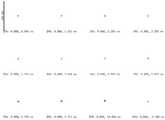
图2是本发明第一实施例的反射式目镜光学系统的点列图示意图;2 is a schematic diagram of a dot diagram of the reflective eyepiece optical system according to the first embodiment of the present invention;
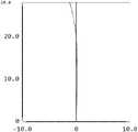
图3a是本发明第一实施例的反射式目镜光学系统的场曲示意图;3a is a schematic diagram of the field curvature of the reflective eyepiece optical system according to the first embodiment of the present invention;
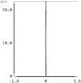
图3b是本发明第一实施例的反射式目镜光学系统的畸变示意图;3b is a schematic diagram of the distortion of the reflective eyepiece optical system according to the first embodiment of the present invention;
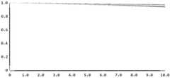
图4是本发明第一实施例的反射式目镜光学系统的光学传递函数MTF曲线图;Fig. 4 is the optical transfer function MTF curve diagram of the reflective eyepiece optical system of the first embodiment of the present invention;
图5是本发明第二实施例的反射式目镜光学系统的光路结构图;Fig. 5 is the optical path structure diagram of the reflective eyepiece optical system of the second embodiment of the present invention;
图6是本发明第二实施例的反射式目镜光学系统的点列图示意图;6 is a schematic point diagram of a reflective eyepiece optical system according to a second embodiment of the present invention;
图7a是本发明第二实施例的反射式目镜光学系统的场曲示意图;7a is a schematic diagram of the field curvature of the reflective eyepiece optical system according to the second embodiment of the present invention;
图7b是本发明第二实施例的反射式目镜光学系统的畸变示意图;7b is a schematic diagram of the distortion of the reflective eyepiece optical system according to the second embodiment of the present invention;
图8是本发明第二实施例的反射式目镜光学系统的光学传递函数MTF曲线图;Fig. 8 is the optical transfer function MTF curve diagram of the reflective eyepiece optical system of the second embodiment of the present invention;
图9a是本发明第三实施例的反射式目镜光学系统的光路结构正视图;9a is a front view of an optical path structure of a reflective eyepiece optical system according to a third embodiment of the present invention;
图9b是本发明第三实施例的反射式目镜光学系统的光路结构俯视图;9b is a top view of the optical path structure of the reflective eyepiece optical system according to the third embodiment of the present invention;
图10是本发明第三实施例的反射式目镜光学系统的点列图示意图;10 is a schematic diagram of a dot diagram of a reflective eyepiece optical system according to a third embodiment of the present invention;
图11a是本发明第三实施例的反射式目镜光学系统的场曲示意图;11a is a schematic diagram of the field curvature of the reflective eyepiece optical system according to the third embodiment of the present invention;
图11b是本发明第三实施例的反射式目镜光学系统的畸变示意图;11b is a schematic diagram of distortion of the reflective eyepiece optical system according to the third embodiment of the present invention;
图12是本发明第三实施例的反射式目镜光学系统的光学传递函数MTF曲线图;Fig. 12 is the optical transfer function MTF curve diagram of the reflective eyepiece optical system of the third embodiment of the present invention;
图13a是本发明第四实施例的反射式目镜光学系统的光路结构正视图;13a is a front view of the optical path structure of the reflective eyepiece optical system according to the fourth embodiment of the present invention;
图13b是本发明第四实施例的反射式目镜光学系统的光路结构俯视图;13b is a top view of the optical path structure of the reflective eyepiece optical system according to the fourth embodiment of the present invention;
图14是本发明第四实施例的反射式目镜光学系统的点列图示意图;14 is a schematic point diagram of a reflective eyepiece optical system according to a fourth embodiment of the present invention;
图15a是本发明第四实施例的反射式目镜光学系统的场曲示意图;15a is a schematic diagram of the field curvature of the reflective eyepiece optical system according to the fourth embodiment of the present invention;
图15b是本发明第四实施例的反射式目镜光学系统的畸变示意图;15b is a schematic diagram of distortion of the reflective eyepiece optical system according to the fourth embodiment of the present invention;
图16是本发明第四实施例的反射式目镜光学系统的光学传递函数MTF曲线图;Fig. 16 is the optical transfer function MTF curve diagram of the reflective eyepiece optical system of the fourth embodiment of the present invention;
图17是本发明第五实施例的反射式目镜光学系统的光路结构图;Fig. 17 is the optical path structure diagram of the reflective eyepiece optical system of the fifth embodiment of the present invention;
图18是本发明第五实施例的反射式目镜光学系统的点列图示意图;18 is a schematic point diagram of a reflective eyepiece optical system according to a fifth embodiment of the present invention;
图19a是本发明第五实施例的反射式目镜光学系统的场曲示意图;19a is a schematic diagram of the field curvature of the reflective eyepiece optical system according to the fifth embodiment of the present invention;
图19b是本发明第五实施例的反射式目镜光学系统的畸变示意图;19b is a schematic diagram of the distortion of the reflective eyepiece optical system according to the fifth embodiment of the present invention;
图20是本发明第五实施例的反射式目镜光学系统的光学传递函数MTF曲线图。20 is an optical transfer function MTF curve diagram of the reflective eyepiece optical system according to the fifth embodiment of the present invention.
具体实施方式Detailed ways
为了使本发明实施例的目的、技术方案和优点更加清楚,下面将结合本发明实施例中的技术方案进行清楚、完整的描述,显然,所描述的实施例是本发明的部分实施例,而不是全部实施例。基于本发明的实施例,本领域普通技术人员在没有付出创造性劳动的前提下所获得的所有其他实施例,都属于本发明的保护范围。In order to make the purposes, technical solutions and advantages of the embodiments of the present invention clearer, the following will be described clearly and completely in combination with the technical solutions in the embodiments of the present invention. Obviously, the described embodiments are part of the embodiments of the present invention, and Not all examples. Based on the embodiments of the present invention, all other embodiments obtained by those of ordinary skill in the art without creative work fall within the protection scope of the present invention.
本发明构造一种反射式目镜光学系统,包括:沿人眼光轴入射方向依次设置的第一光学元件和第二光学元件,以及位于微型图像显示器光轴上的第一透镜组;第一光学元件用于透射和反射来自于微型图像显示器的图像光;第二光学元件包含一个光学反射面,且光学反射面凹向人眼观看方向;第一光学元件将经过第一透镜组折射的图像光反射至第二光学元件上,再将经第二光学元件反射的图像光透射至人眼处;The present invention constructs a reflective eyepiece optical system, comprising: a first optical element and a second optical element arranged in sequence along the incident direction of the optical axis of the human eye, and a first lens group located on the optical axis of a micro-image display; the first optical element It is used to transmit and reflect the image light from the micro image display; the second optical element includes an optical reflection surface, and the optical reflection surface is concave to the viewing direction of the human eye; the first optical element reflects the image light refracted by the first lens group onto the second optical element, and then transmit the image light reflected by the second optical element to the human eye;
目镜光学系统的有效焦距为fw,第一透镜组的有效焦距为f1,第二光学元件的有效焦距为f2,则fw、f1、f2满足下列关系式(1)、(2):The effective focal length of the eyepiece optical system is fw , the effective focal length of the first lens group is f1 , and the effective focal length of the second optical element is f2 , then fw , f1 , f2 satisfy the following relational expressions (1), ( 2):
f1/fw < -0.47 (1);f1 /fw < -0.47 (1);
-2.53<f2/fw<-0.64 (2);-2.53<f2 /fw <-0.64 (2);
其中f1/fw可取值为-100.57、-56.55、-33.351、-21.131、-10.951、-7.935、-5.815、-3.615、-1.589、-0.47等等,f2/fw可取值为-2.53、-2.521、-2.13、-1.99、-1.55、-1.21、-1.02、-0.98、-0.875、-0.753、-0.659、-0.64等等。Among them, f1 /fw can take values of -100.57, -56.55, -33.351, -21.131, -10.951, -7.935, -5.815, -3.615, -1.589, -0.47, etc., f2 /fw can take values is -2.53, -2.521, -2.13, -1.99, -1.55, -1.21, -1.02, -0.98, -0.875, -0.753, -0.659, -0.64, and so on.
第一透镜组包括从人眼观看侧向微型图像显示器侧沿光轴方向共轴依次排列的第一子透镜组、第二子透镜组、第三子透镜组和第四子透镜组;第一子透镜组、第二子透镜组与第三子透镜组的有效焦距为正、负、正组合;第一子透镜组的有效焦距为f11,第二子透镜组的有效焦距为f12,第三子透镜组的有效焦距为f13,则f11、f12、f13和f1满足下列关系式(3)、(4)、(5):The first lens group includes a first sub-lens group, a second sub-lens group, a third sub-lens group and a fourth sub-lens group which are coaxially arranged in sequence along the optical axis from the side of the human eye to the side of the micro-image display; the first sub-lens group The effective focal lengths of the sub-lens group, the second sub-lens group and the third sub-lens group are positive, negative and positive combinations; the effective focal length of the first sub-lens group is f11 , the effective focal length of the second sub-lens group is f12 , The effective focal length of the third sub-lens group is f13 , then f11 , f12 , f13 and f1 satisfy the following relational expressions (3), (4), (5):
0.19 < f11/f1 (3);0.19 < f11 /f1 (3);
f12/f1<-0.019 (4);f12 /f1 <-0.019 (4);
0.019 < f13/f1 (5)。0.019 < f13 /f1 (5).
其中f11/f1可取值为0.19、0.20、0.39、0.57、0.77、0.89、1.35、3.25、5.56、36.1、54.1、87.6等等,f12/f1可取值为-120.43、-100.47、-77.55、-51.25、-45.33、-21.78、-15.13、-10.55、-7.15、-4.14、-0.13、-0.02、-0.019等等,f13/f1可取值为0.019、0.020、0.139、1.99、5.83、12.13、22.54、35.24、43.55、83.59等等。Among them, f11 /f1 can be 0.19, 0.20, 0.39, 0.57, 0.77, 0.89, 1.35, 3.25, 5.56, 36.1, 54.1, 87.6, etc., and f12 /f1 can be -120.43, -100.47 , -77.55, -51.25, -45.33, -21.78, -15.13, -10.55, -7.15, -4.14, -0.13, -0.02, -0.019, etc., f13 /f1 can be 0.019, 0.020, 0.139 , 1.99, 5.83, 12.13, 22.54, 35.24, 43.55, 83.59, etc.
上述关系式(1)、(2)、(3)、(4)、(5)中,f1/fw、f2/fw、f11/f1、f12/f1和f13/f1的取值范围对系统像差的校正、光学元件的加工难度、以及光学元件装配偏差的灵敏度密切相关,其中关系式(1)中f1/fw的取值小于-0.47,改善了所述系统中光学元件的可加工性;关系式(2)中的f2/fw取值大于-2.53,改善了所述系统中光学元件的可加工性,其取值小于-0.64,使系统像差得以充分校正,从而实现更加优质的光学效果。关系式(3)中f11/f1的取值大于0.19,使系统像差得以充分校正,从而实现优质的光学效果;关系式(5)中f13/f1的取值大于0.019,使系统像差得以充分校正,从而实现优质的光学效果。关系式(4)中f12/f1的取值小于-0.019,降低了球差的校正难度,便于实现大光学孔径。In the above relational expressions (1), (2), (3), (4) and (5), f1 /fw , f2 /fw , f11 /f1 , f12 /f1 and f13 The value rangeof /f1 is closely related to the correction of system aberrations, the processing difficulty of optical components, and the sensitivity of optical component assembly deviations. The machinability of the optical element in the system is improved; the value of f2 /fw in the relational formula (2) is greater than -2.53, which improves the machinability of the optical element in the system, and its value is less than -0.64, The system aberrations can be fully corrected, so as to achieve higher quality optical effects. The value of f11 /f1 in the relationship (3) is greater than 0.19, so that the system aberration can be fully corrected to achieve high-quality optical effects; the value of f13 /f1 in the relationship (5) is greater than 0.019, so that the System aberrations are fully corrected for high-quality optical results. The value of f12 /f1 in the relational formula (4) is less than -0.019, which reduces the difficulty of spherical aberration correction and facilitates the realization of a large optical aperture.
其中,第一透镜组包含四个子透镜组,分别是相邻设置的第一子透镜组、第二子透镜组、第三子透镜组与第四子透镜组,第一子透镜组、第二子透镜组与第三子透镜组采用正、负、正的焦距组合,第四子透镜组的焦距可以为正焦距或者负焦距,其中,负透镜组矫正像差,正透镜组提供聚焦成像。各子透镜组之间采用“正、负、正、正”或者“正、负、正、负”的焦距组合,子透镜组组合较为复杂,能够进一步矫正像差,加工性更好,充分地矫正了系统的像差,提升了系统的光学分辨力。Wherein, the first lens group includes four sub-lens groups, which are a first sub-lens group, a second sub-lens group, a third sub-lens group and a fourth sub-lens group which are arranged adjacently. The sub-lens group and the third sub-lens group adopt a combination of positive, negative and positive focal lengths, and the focal length of the fourth sub-lens group can be positive or negative, wherein the negative lens group corrects aberrations, and the positive lens group provides focused imaging. The focal length combination of "positive, negative, positive, positive" or "positive, negative, positive, negative" is used between each sub-lens group. The combination of sub-lens groups is more complicated, which can further correct aberrations, and has better processability. The aberration of the system is corrected and the optical resolution of the system is improved.
更重要的是,利用第一光学元件具有的透射和反射性能,第二光学元件具有一个反射面,对光路进行有效的折叠,减小了目镜光学系统的整体尺寸,提高了后续量产的可能性,在产品小尺寸化、降低成本和重量的基础上,实现光学系统像差的大幅消除,同时也提高了基本的光学指标,保证很高的成像质量的同时,提高了画角的大小,观察者可以通过本发明,观看到全画幅高清、无失真、像质均匀的大幅画面,达到高临场感的视觉体验,本产品适用于头戴近眼显示装置及其类似装置。More importantly, using the transmission and reflection properties of the first optical element, the second optical element has a reflective surface, which effectively folds the optical path, reduces the overall size of the eyepiece optical system, and improves the possibility of subsequent mass production. On the basis of small size, cost and weight reduction, the aberration of the optical system is greatly eliminated, and the basic optical indicators are also improved to ensure high imaging quality and increase the size of the picture angle. Through the present invention, an observer can watch a large picture with full-frame high-definition, no distortion and uniform image quality, so as to achieve a high-presence visual experience. This product is suitable for head-mounted near-eye display devices and similar devices.
上述实施例中,第一光学元件可以为75%透射,25%反射或65%透射,35%反射或具有透射反射功能的偏振片。第二光学元件只是具有反射功能的部件,可以是镜片,也可以是具有反射功能的金属件。In the above embodiment, the first optical element may be a polarizer with 75% transmission, 25% reflection or 65% transmission, 35% reflection or a transflective function. The second optical element is only a component with a reflective function, which can be a lens or a metal piece with a reflective function.
如图1所示,包括从人眼观察侧到微型图像显示器之间沿光轴方向排列的第一光学元件、第二光学元件、第一透镜组;其中,以靠近人眼E侧的光学表面序号为1,依此类推(从左至右为2、3、4、5、6······),从微型图像显示器发出的光,经第一透镜组折射后,在第一光学元件上反射至第二光学元件上,第二光学元件将光反射至至第一光学元件上,再经过第一光学元件透射至人眼。As shown in Figure 1, it includes a first optical element, a second optical element, and a first lens group arranged along the optical axis from the observation side of the human eye to the micro-image display; wherein, the optical surface close to the E side of the human eye The serial number is 1, and so on (from left to right: 2, 3, 4, 5, 6...), the light emitted from the micro-image display is refracted by the first lens group, The element is reflected to the second optical element, and the second optical element reflects the light to the first optical element, and then transmits the light to the human eye through the first optical element.
在进一步的实施例中,第一光学元件和第二光学元件沿光轴的距离为d1,第一光学元件和第一透镜组沿光轴的距离为d2,则d1和d2满足下列关系式(6):In a further embodiment, the distance between the first optical element and the second optical element along the optical axis is d1 , and the distance between the first optical element and the first lens group along the optical axis is d2 , then d1 and d2 satisfy The following relational formula (6):
0.82 < d2/d1 (6)。0.82 < d2 /d1 (6).
其中,d2/d1可取值为0.82、0.83、0.88、0.98、1.55、2.37、3.55、3.88、3.99、4.57、4.89、4.99等等。Wherein, d2 /d1 can be 0.82, 0.83, 0.88, 0.98, 1.55, 2.37, 3.55, 3.88, 3.99, 4.57, 4.89, 4.99 and so on.
上述关系式(6)中d2/d1的下限取值大于0.82,降低了系统离轴像差的校正难度,确保中心视场和边缘视场同时达到较高的图像质量,使全画幅内像质均匀。The lower limit of d2 /d1 in the above relationship (6) is greater than 0.82, which reduces the difficulty of correcting the off-axis aberration of the system, ensures that the center field of view and the edge field of view achieve high image quality at the same time, and makes the full-frame Image quality is uniform.
在进一步的实施例中,第二光学元件的最大光学有效口径为φ2,则满足下列关系式(7):In a further embodiment, the maximum optical effective aperture of the second optical element is φ2 , which satisfies the following relational formula (7):
φ2 < 70mm (7)。φ2 < 70mm (7).
其中,φ2可取值为70、69、65、56、52、48、32、30、28、26、21等等,单位mm。Among them, φ2 can be 70, 69, 65, 56, 52, 48, 32, 30, 28, 26, 21, etc., and the unit is mm.
在进一步的实施例中,第一子透镜组的有效焦距f11、第二子透镜组的有效焦距为f12、第三子透镜组的有效焦距为f13以及第一透镜组的有效焦距为f1,进一步满足下列关系式(8)、(9)、(10):In a further embodiment, the effective focal length of the first sub-lens group is f11 , the effective focal length of the second sub-lens group is f12 , the effective focal length of the third sub-lens group is f13 , and the effective focal length of the first lens group is f1 , further satisfies the following relational expressions (8), (9), (10):
0.78 < f11/ f1 <1.06 (8);0.78 < f11 / f1 < 1.06 (8);
-1.16< f12/ f1 < -0.90 (9);-1.16 < f12 / f1 < -0.90 (9);
1.38 < f13/ f1 < 3.6 (10)。1.38 < f13 / f1 < 3.6 (10).
其中f11/f1可取值为0.78、0.79、0.81、0.83、0.85、0.895、0.954、1.0、1.05、1.06等等,f12/f1可取值为-1.16、-1.15、-1.12、-1.10、-1.07、-1.06、-1.03、-1.01、-0.95、-0.91、-0.90等等,f13/f1可取值为1.38、1.39、1.963、2.19、2.345、2.548、2.854、2.961、3.54、3.59、3.6等等。Among them, f11 /f1 can be 0.78, 0.79, 0.81, 0.83, 0.85, 0.895, 0.954, 1.0, 1.05, 1.06, etc., and f12 /f1 can be -1.16, -1.15, -1.12, -1.10, -1.07, -1.06, -1.03, -1.01, -0.95, -0.91, -0.90, etc., f13 /f1 can be 1.38, 1.39, 1.963, 2.19, 2.345, 2.548, 2.854, 2.961 , 3.54, 3.59, 3.6, etc.
通过进一步优选第一子透镜组、第二子透镜组、第三子透镜组和系统有效焦距的取值范围,更好地平衡了所述光学系统的光学性能和加工制造难度。By further optimizing the value ranges of the first sub-lens group, the second sub-lens group, the third sub-lens group and the effective focal length of the system, the optical performance and the difficulty of processing and manufacturing of the optical system are better balanced.
在其中一个实施例中,第一子透镜组由一片光学透镜构成;其中第一子透镜组包括第一透镜;第一透镜为正透镜。In one of the embodiments, the first sub-lens group is composed of a piece of optical lens; wherein the first sub-lens group includes a first lens; and the first lens is a positive lens.
在其中一个实施例中,第一子透镜组由两片透镜构成,分别是远离微型图像显示器侧的第一透镜和靠近微型图像显示器侧的第二透镜;第一透镜和第二透镜均为正透镜。In one of the embodiments, the first sub-lens group is composed of two lenses, which are respectively a first lens on the side away from the micro-image display and a second lens on the side close to the micro-image display; both the first lens and the second lens are positive lens.
在进一步的实施例中,第一透镜的有效焦距为f111,第一子透镜组的有效焦距为f11,则f111、f11满足下列关系式(11):In a further embodiment, the effective focal length of the first lens is f111 , and the effective focal length of the first sub-lens group is f11 , then f111 and f11 satisfy the following relational formula (11):
0.10< │f111/ f11│ (11);0.10< │f111 / f11 │ (11);
其中│f111/ f11│可取值为0.10、0.11、0.22、0.58、1.32、1.55、2.25、3.57、5.57、8.79、9.91、10.11、20.22等等。where │f111 / f11 │ can be 0.10, 0.11, 0.22, 0.58, 1.32, 1.55, 2.25, 3.57, 5.57, 8.79, 9.91, 10.11, 20.22 and so on.
关系式(11)中│f111/ f11│的取值大于0.10,使系统像差得以充分校正,从而实现优质的光学效果。The value of │f111 / f11 │ in the relational formula (11) is greater than 0.10, so that the system aberration can be fully corrected, thereby achieving high-quality optical effects.
在进一步的实施例中,第一透镜靠近人眼侧的光学面凸向人眼方向。In a further embodiment, the optical surface of the first lens close to the human eye is convex toward the human eye.
上述实施例进一步改善了系统的像散和场曲等像差,有利于目镜系统实现全画幅均匀像质的高分辨率光学效果。The above-mentioned embodiments further improve aberrations such as astigmatism and field curvature of the system, which is beneficial for the eyepiece system to achieve a high-resolution optical effect of uniform image quality across the entire frame.
在进一步的实施例中,第二子透镜组由一片透镜构成,其中第二子透镜组包括与第一子透镜组近邻的第三透镜;第三透镜为负透镜;第三透镜的有效焦距为f121,则f121满足下列关系式(12):In a further embodiment, the second sub-lens group is composed of one lens, wherein the second sub-lens group includes a third lens adjacent to the first sub-lens group; the third lens is a negative lens; the effective focal length of the third lens is f121 , then f121 satisfies the following relational expression (12):
f121 < -5.38 (12);f121 < -5.38 (12);
其中f121可取值为-5.38、-5.39、-6.72、-9.88、-21.32、-41.55、-52.25、-63.57、-75.57、-88.79、-99.91、-110.11、-220.22等等。关系式(12)中f121其取值小于-5.38,降低了球差的校正难度,便于实现大光学孔径。Among them, f121 can be -5.38, -5.39, -6.72, -9.88, -21.32, -41.55, -52.25, -63.57, -75.57, -88.79, -99.91, -110.11, -220.22 and so on. In the relational formula (12), the value of f121 is less than -5.38, which reduces the difficulty of spherical aberration correction and facilitates the realization of large optical apertures.
在进一步的实施例中,第三子透镜组由一片透镜构成,其中,第三子透镜组包括与第二子透镜组近邻第四透镜;第四透镜为正透镜;第四透镜的有效焦距为f131,则f131满足下列关系式(13):In a further embodiment, the third sub-lens group is composed of one lens, wherein the third sub-lens group includes a fourth lens adjacent to the second sub-lens group; the fourth lens is a positive lens; and the effective focal length of the fourth lens is f131 , then f131 satisfies the following relational expression (13):
8.82 < f131 (13)。8.82 < f131 (13).
其中,f131可取值为8.82、8.83、9.72、19.88、21.32、41.55、52.25、63.57、75.57、88.79、99.91、110.11、220.22等等。关系式(13)中f131取值大于8.82,使系统像差得以充分校正,从而实现优质的光学效果。Among them, f131 can be 8.82, 8.83, 9.72, 19.88, 21.32, 41.55, 52.25, 63.57, 75.57, 88.79, 99.91, 110.11, 220.22 and so on. The value of f131 in the relational formula (13) is greater than 8.82, so that the system aberration can be fully corrected, thereby achieving high-quality optical effects.
在进一步的实施例中,第四子透镜组由一片透镜构成,其中,第四子透镜组包括与第三子透镜组近邻第五透镜;第五透镜靠近微型图像显示器侧的光学面凹向微型图像显示器方向;第五透镜的有效焦距为为f141,则f141满足下列关系式(14):In a further embodiment, the fourth sub-lens group is composed of one lens, wherein the fourth sub-lens group includes a fifth lens adjacent to the third sub-lens group; the optical surface of the fifth lens close to the micro-image display side is concave to the micro Image display direction; the effective focal length of the fifth lens is f141 , then f141 satisfies the following relational formula (14):
2.15< │f141/ f1│ (14)。2.15< │f141 / f1 │ (14).
其中,│f141/ f1│可取值为2.15、2.16、5.25、8.1、14.14、26.53、48.78、100、225等等。关系式(14)中│f141/ f1│的取值大于2.15,使系统像差得以充分校正,从而实现优质的光学效果。Among them, │f141 / f1 │ can be 2.15, 2.16, 5.25, 8.1, 14.14, 26.53, 48.78, 100, 225 and so on. The value of │f141 / f1 │ in the relational formula (14) is greater than 2.15, so that the system aberration can be fully corrected, thereby achieving high-quality optical effects.
在进一步的实施例中,第五透镜与微型图像显示器可沿光轴一同移动,用于调节目镜光学系统的等效目视虚像距离。通过沿光轴方向同时移动第五透镜和目镜光学系统像面位置,可以调节目镜光学系统的等效目视虚像距离。In a further embodiment, the fifth lens and the miniature image display can be moved together along the optical axis for adjusting the equivalent visual virtual image distance of the optical system of the mirror. By simultaneously moving the image plane positions of the fifth lens and the eyepiece optical system along the optical axis direction, the equivalent visual virtual image distance of the eyepiece optical system can be adjusted.
在进一步的实施例中,第一透镜组中包含一个或多个偶次非球面面型;第五透镜的两个光学面均为偶次非球面面型;第二光学元件的两个光学面均为偶次非球面面型。In a further embodiment, the first lens group includes one or more even-order aspherical surfaces; the two optical surfaces of the fifth lens are both even-ordered aspherical surfaces; the two optical surfaces of the second optical element All are even-order aspherical surfaces.
使所述光学系统的各级像差得到进一步的优化校正。进一步提升所述目镜光学系统的光学性能。The aberrations at all levels of the optical system are further optimized and corrected. The optical performance of the eyepiece optical system is further improved.
在进一步的实施例中,偶次非球面面型满足下列关系式(15):In a further embodiment, the even-order aspheric shape satisfies the following relation (15):

其中,z为光学面的矢高,c为非球面顶点处曲率,k为非球面系数,α2,4,6… 为各阶系数,r为曲面上点到透镜系统光轴的距离坐标。Among them, z is the sag of the optical surface, c is the curvature at the vertex of the aspheric surface, k is the aspheric coefficient, α2, 4, 6... are the coefficients of each order, and r is the distance coordinate from the point on the surface to the optical axis of the lens system.
使所述光学系统的像差(包括球差、慧差、畸变、场曲、像散、色差和其它高阶像差)得到充分的校正,有利于所述目镜光学系统在实现大视场角、大孔径的同时,进一步提升中心视场和边缘视场的图像质量、缩小中心视场和边缘视场图像质量的差别,实现全画幅内更均匀的图像质量和低畸变。The aberrations of the optical system (including spherical aberration, coma, distortion, field curvature, astigmatism, chromatic aberration and other higher-order aberrations) are fully corrected, which is beneficial for the eyepiece optical system to achieve a large field of view , At the same time of large aperture, the image quality of the central field of view and the edge of the field of view is further improved, the difference between the image quality of the center and the edge of the field of view is reduced, and the image quality and low distortion in the full frame are more uniform.
在进一步的实施例中,第一光学元件为平面半透半反光学元件,第一光学元件的反射率为Re1,则Re1满足关系式(16):In a further embodiment, the first optical element is a plane transflective optical element, and the reflectivity of the first optical element is Re1 , then Re1 satisfies the relational formula (16):
20% < Re1< 80% (16);20% < Re1 < 80% (16);
其中Re1可取值为20%、21%、30%、47%、52%、60%、65%、70%、79%等等。Among them, Re1 can be 20%, 21%, 30%, 47%, 52%, 60%, 65%, 70%, 79% and so on.
在进一步的实施例中,第二光学元件包含两个面型相同的共轴光学面。In a further embodiment, the second optical element comprises two coaxial optical surfaces of the same surface type.
在进一步的实施例中,光学反射面的反射率为Re2,则Re2满足下列关系式(17):In a further embodiment, the reflectivity of the optical reflection surface is Re2 , then Re2 satisfies the following relational formula (17):
20% < Re2 (17);20% < Re2 (17);
其中Re2可取值为20%、21%、30%、47%、52%、60%、65%、70%、80%、99%等等。Among them, Re2 can be 20%, 21%, 30%, 47%, 52%, 60%, 65%, 70%, 80%, 99% and so on.
在进一步的实施例中,第一透镜组和第二光学元件的光轴夹角为λ1,则λ1满足下列关系式(18):In a further embodiment, the included angle between the optical axis of the first lens group and the second optical element is λ1 , then λ1 satisfies the following relational expression (18):
55°< λ1 < 120 ° (18);55°< λ1 < 120° (18);
其中,λ1可取值为55°、60°、66°、70°、90°、100°、115°、120°等等。Wherein, λ1 can be 55°, 60°, 66°, 70°, 90°, 100°, 115°, 120° and so on.
在其中一个实施例中,目镜光学系统还包括位于第一透镜组和第一光学元件之间的平面反射光学元件;平面反射光学元件将经过第一透镜组折射的图像光反射至第一光学元件上,第一光学元件将图像光反射至第二光学元件上,再将经第二光学元件反射的图像光透射至人眼处;In one of the embodiments, the eyepiece optical system further includes a plane reflection optical element located between the first lens group and the first optical element; the plane reflection optical element reflects the image light refracted by the first lens group to the first optical element On, the first optical element reflects the image light to the second optical element, and then transmits the image light reflected by the second optical element to the human eye;
第一透镜组与第一光学元件的夹角为λ2,则λ2满足下列关系式(19):The angle between the first lens group and the first optical element is λ2 , then λ2 satisfies the following relational expression (19):
60° ≤λ2 ≤ 180 ° (19)。60° ≤λ2 ≤ 180° (19).
其中λ2可取值为60°、74°、80°、90°、100°、130°、140°、155°、167°、180°等等。Wherein, λ2 can be 60°, 74°, 80°, 90°, 100°, 130°, 140°, 155°, 167°, 180° and so on.
在进一步的实施例中,第二光学元件的材质为光学塑胶材料。如:E48R、EP5000、OKP1等等。In a further embodiment, the material of the second optical element is an optical plastic material. Such as: E48R, EP5000, OKP1 and so on.
使得所述目镜光学系统的各级像差得到充分校正的同时,又控制了光学元件的制造成本和光学系统的重量。The aberrations of all levels of the eyepiece optical system are fully corrected, and the manufacturing cost of the optical element and the weight of the optical system are also controlled.
下面通过更加具体的实施例对上述目镜光学系统的原理、方案及显示结果进行更进一步的阐述。The principles, solutions and display results of the above-mentioned eyepiece optical system will be further described below through more specific embodiments.
以下实施例中,光阑E可以为目镜光学系统成像的出瞳,为一个虚拟的出光孔径,人眼的瞳孔在光阑位置时,可以观察到最佳的成像效果。以下实施例所提供的点列图反映光学系统成像的几何结构,忽略衍射效应,以指定视场、指定波长光线聚焦像平面截面形成的弥散斑表示,可同时包含多个视场和多种波长的光线。因此,可以通过点列图弥散斑的密集程度、形状尺寸直观地衡量光学系统成像质量的优劣,通过点阵图不同波长弥散斑的错位程度直观衡量光学系统的色差,点列图的RMS (Root Meam Square)半径(均方根半径)越小,光学系统的成像质量越高。In the following embodiments, the diaphragm E may be the exit pupil of the eyepiece optical system for imaging, which is a virtual light exit aperture. When the pupil of the human eye is at the diaphragm position, the best imaging effect can be observed. The spot diagrams provided in the following examples reflect the imaging geometry of the optical system, ignoring the diffraction effect, and are represented by the speckle formed by the cross-section of the focused image plane of the specified field of view and the light of the specified wavelength, which can include multiple fields of view and multiple wavelengths at the same time. of light. Therefore, the quality of the imaging quality of the optical system can be directly measured by the density, shape and size of the dot pattern, and the chromatic aberration of the optical system can be directly measured by the dislocation degree of the dot pattern with different wavelengths. The RMS of the dot pattern ( The smaller the Root Meam Square radius (root mean square radius), the higher the imaging quality of the optical system.
第一实施例first embodiment
所述第一实施例目镜设计数据如下表一所示:The eyepiece design data of the first embodiment are shown in Table 1 below:

附图1为第一实施例的目镜光学系统光路图,包括:沿人眼光轴入射方向依次设置的第一光学元件L1和第二光学元件T2,以及位于微型图像显示器IMG光轴上的第一透镜组T1;第一光学元件L1同时具备透射和反射的光学性能。第一光学元件L1用于透射和反射来自于微型图像显示器IMG的图像光;第二光学元件T2包含一个光学反射面L2,且光学反射面L2凹向人眼EYE观看方向;第一光学元件L1将经过第一透镜组T1折射的图像光反射至第二光学元件T2上,再将经第二光学元件T2反射的图像光透射至人眼EYE处;1 is an optical path diagram of the eyepiece optical system of the first embodiment, including: a first optical element L1 and a second optical element T2 arranged in sequence along the incident direction of the optical axis of the human eye, and a first optical element located on the optical axis of the micro-image display IMG The lens group T1; the first optical element L1 has both transmission and reflection optical properties. The first optical element L1 is used to transmit and reflect the image light from the micro image display IMG; the second optical element T2 includes an optical reflection surface L2, and the optical reflection surface L2 is concave to the viewing direction of the human eye EYE; the first optical element L1 Reflecting the image light refracted by the first lens group T1 to the second optical element T2, and then transmitting the image light reflected by the second optical element T2 to the human eye EYE;
所述目镜光学系统的有效焦距fw为-26.08,所述第一透镜组T1的有效焦距f1为12.52,第二光学元件T2的有效焦距f2为20.49,第一光学元件L1和第二光学元件T2沿光轴的距离d1为20,第一光学元件L1和第一透镜组T1沿光轴的距离d2为32.07,其中第一透镜组T1包括第一子透镜组T11、第二子透镜组T12、第三子透镜组T13、第四子透镜组T14,第一子透镜组T11由一片正透镜构成,该透镜为第一透镜T111,第一子透镜组T11的有效焦距f11为9.95,第二子透镜组T12由一片负透镜构成,该透镜为第三透镜T121,第三子透镜组T13由一片正透镜构成,该透镜为第四透镜T131.第四子透镜组T14由第五透镜T141构成。第二子透镜组T12的有效焦距f12为-11.37,第一透镜T111有效焦距f111为9.95,第三子透镜组T13的有效焦距f13为19.33,第四子透镜组T14的有效焦距f14为64.06。则f1/fw为-0.48,f2/fw为-0.78,f11/f1为0.79,f111/f11为1,f12/f1为-0.91,f13/f1为1.54,f14/f1为5.12,f121为-11.37,d2/d1为1.54,λ1为72°。The effective focal length fw of the eyepiece optical system is -26.08, the effective focal length f1 of the first lens group T1 is 12.52, the effective focal length f2 of the second optical element T2 is 20.49, the first optical element L1 and the second The distance d1 of the optical element T2 along the optical axis is 20, and the distance d2 of the first optical element L1 and the first lens group T1 along the optical axis is 32.07, wherein the first lens group T1 includes the first sub-lens group T11, the second The sub-lens group T12, the third sub-lens group T13, the fourth sub-lens group T14, the first sub-lens group T11 is composed of a positive lens, the lens is the first lens T111, and the effective focal length of the first sub-lens group T11 f11 is 9.95, the second sub-lens group T12 is composed of a negative lens, which is the third lens T121, and the third sub-lens group T13 is composed of a positive lens, which is the fourth lens T131. The fourth sub-lens group T14 is composed of The fifth lens T141 is constituted. The effective focal length f12 of the second sub-lens groupT12 is -11.37, the effective focal lengthf111 of the first lens T111 is 9.95, the effective focal length f13 of the third sub-lens groupT13 is 19.33, and the effective focal length f of the fourth sub-lens group T1414 is 64.06. Then f1 /fw is -0.48, f2 /fw is -0.78, f11 /f1 is 0.79, f111 /f11 is 1, f12 /f1 is -0.91, and f13 /f1 is 1.54, f14 /f1 is 5.12, f121 is -11.37, d2 /d1 is 1.54, and λ1 is 72°.
附图2、附图3a、附图3b和附图4分别为点列图,场曲、畸变图和传递函数MTF曲线图,反映出了本实施例各个视场光线在像平面(微型图像显示器IMG)的单位像素内有着很高的分辨率及很小的光学畸变,单位周期每10mm分辨率达到0.9以上,光学系统像差以及图像飘移得到良好校正,通过所述目镜光学系统可观察到均匀、高光学性能的显示画像。Accompanying drawing 2, accompanying drawing 3a, accompanying drawing 3b and accompanying drawing 4 are respectively the dot diagram, the field curvature, the distortion diagram and the transfer function MTF curve diagram, reflecting the light of each field of view of the present embodiment in the image plane (miniature image display The unit pixel of IMG) has high resolution and small optical distortion. The resolution per 10mm per unit period reaches more than 0.9. The optical system aberration and image drift are well corrected, and uniformity can be observed through the eyepiece optical system. , Display images with high optical performance.
第二实施例Second Embodiment
所述第二实施例目镜设计数据如下表二所示:The eyepiece design data of the second embodiment are shown in Table 2 below:

附图5为第二实施例的目镜光学系统光路图,包括:沿人眼光轴入射方向依次设置的第一光学元件L1和第二光学元件T2,以及位于微型图像显示器IMG光轴上的第一透镜组T1;第一光学元件L1同时具备透射和反射的光学性能。第一光学元件L1用于透射和反射来自于微型图像显示器IMG的图像光;第二光学元件T2包含一个光学反射面L2,且光学反射面L2凹向人眼EYE观看方向;第一光学元件L1将经过第一透镜组T1折射的图像光反射至第二光学元件T2上,再将经第二光学元件T2反射的图像光透射至人眼EYE处。5 is an optical path diagram of the eyepiece optical system of the second embodiment, including: a first optical element L1 and a second optical element T2 arranged in sequence along the incident direction of the optical axis of the human eye, and a first optical element located on the optical axis of the micro-image display IMG The lens group T1; the first optical element L1 has both transmission and reflection optical properties. The first optical element L1 is used to transmit and reflect the image light from the micro image display IMG; the second optical element T2 includes an optical reflection surface L2, and the optical reflection surface L2 is concave to the viewing direction of the human eye EYE; the first optical element L1 The image light refracted by the first lens group T1 is reflected to the second optical element T2, and then the image light reflected by the second optical element T2 is transmitted to the human eye EYE.
所述目镜光学系统的有效焦距fw为-11.49,所述第一透镜组T1的有效焦距f1为9.73,第二光学元件T2的有效焦距f2为7.47,第一光学元件L1和第二光学元件T2沿光轴的距离d1为17,第一光学元件L1和第一透镜组T1沿光轴的距离d2为23.46,其中第一透镜组T1包括第一子透镜组T11、第二子透镜组T12、第三子透镜组T13、第四子透镜组T14,第一子透镜组T11由一片正透镜组成,该透镜为第一透镜T111,第一子透镜组T11的有效焦距f11为10.18,第二子透镜组T12由一片负透镜组成,该透镜为第三透镜T121, 第三子透镜组T13由一片正透镜构成,该透镜为第四透镜T131.第四子透镜组T14由第五透镜T141构成。第二子透镜组T12的有效焦距f12为-5.39,第三子透镜组T13的有效焦距f13为8.83,第四子透镜组T14的有效焦距f14为21.02。则f1/fw为-0.85,f2/fw为-0.65,f11/f1为1.05,f111/f11为1,f12/f1为-0.55,f13/f1为0.908,f14/f1为2.16,f121为-5.39,d2/d1为1.39,λ1为70°。The effective focal length fw of the eyepiece optical system is -11.49, the effective focal length f1 of the first lens group T1 is 9.73, the effective focal length f2 of the second optical element T2 is 7.47, the first optical element L1 and the second The distance d1 of the optical element T2 along the optical axis is 17, the distance d2 of the first optical element L1 and the first lens group T1 along the optical axis is 23.46, wherein the first lens group T1 includes the first sub-lens group T11, the second The sub-lens group T12, the third sub-lens group T13, the fourth sub-lens group T14, the first sub-lens group T11 is composed of a positive lens, the lens is the first lens T111, and the effective focal length of the first sub-lens group T11 f11 is 10.18, the second sub-lens group T12 is composed of a negative lens, which is the third lens T121, and the third sub-lens group T13 is composed of a positive lens, which is the fourth lens T131. The fourth sub-lens group T14 is composed of The fifth lens T141 is constituted. The effective focal length f12 of the second sub-lens group T12 is -5.39, the effective focal length f13 of the third sub-lens group T13 is 8.83, and the effective focal length f14 of the fourth sub-lens group T14 is 21.02. Then f1 /fw is -0.85, f2 /fw is -0.65, f11 /f1 is 1.05, f111 /f11 is 1, f12 /f1 is -0.55, and f13 /f1 is 0.908, f14 /f1 is 2.16, f121 is -5.39, d2 /d1 is 1.39, and λ1 is 70°.
附图6、附图7a、附图7b和附图8分别为点列图,场曲、畸变图和传递函数MTF曲线图,反映出了本实施例各个视场光线在像平面(微型图像显示器IMG)的单位像素内有着很高的分辨率及很小的光学畸变,单位周期每10mm分辨率达到0.9以上,光学系统像差以及图像飘移得到良好校正,通过所述目镜光学系统可观察到均匀、高光学性能的显示画像。Fig. 6, Fig. 7a, Fig. 7b and Fig. 8 are respectively the point diagram, the field curvature, the distortion diagram and the MTF curve diagram of the transfer function, which reflect the light of each field of view in the present embodiment on the image plane (miniature image display device). The unit pixel of IMG) has high resolution and small optical distortion. The resolution per 10mm per unit period reaches more than 0.9. The optical system aberration and image drift are well corrected, and uniformity can be observed through the eyepiece optical system. , Display images with high optical performance.
第三实施例Third Embodiment
所述第三实施例目镜设计数据如下表三所示:The eyepiece design data of the third embodiment are shown in Table 3 below:

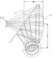
附图9a和图9b为第三实施例的光路结构正视图和俯视图,包括:沿人眼光轴入射方向依次设置的第一光学元件L1和第二光学元件T2,以及位于微型图像显示器IMG光轴上的第一透镜组T1,还包括位于第一透镜组和第一光学元件之间的平面反射光学元件L3;第一光学元件L1同时具备透射和反射的光学性能。第一光学元件L1用于透射和反射来自于微型图像显示器IMG的图像光;第二光学元件T2包含一个光学反射面L2,且光学反射面L2凹向人眼EYE观看方向;平面反射光学元件L3将经过第一透镜组T1折射的图像光反射至第一光学元件L1上,第一光学元件L1将图像光反射至第二光学元件T2上,再将经第二光学元件T2反射的图像光透射至人眼EYE处。9a and 9b are the front view and the top view of the optical path structure of the third embodiment, including: the first optical element L1 and the second optical element T2 arranged in sequence along the incident direction of the optical axis of the human eye, and the optical axis of the micro-image display IMG The first lens group T1 above also includes a plane reflective optical element L3 located between the first lens group and the first optical element; the first optical element L1 has both transmission and reflection optical properties. The first optical element L1 is used to transmit and reflect the image light from the miniature image display IMG; the second optical element T2 includes an optical reflection surface L2, and the optical reflection surface L2 is concave to the viewing direction of the human eye EYE; the plane reflection optical element L3 Reflect the image light refracted by the first lens group T1 to the first optical element L1, the first optical element L1 reflects the image light to the second optical element T2, and then transmit the image light reflected by the second optical element T2 to the human eye EYE.
目镜光学系统的有效焦距fw为-16.8,所述第一透镜组T1的有效焦距f1为18.43,第二光学元件T2的有效焦距f2为27.83,第一光学元件L1和第二光学元件T2沿光轴的距离d1为22.6,第一光学元件L1和第一透镜组T1沿光轴的距离d2为48.16,其中第一透镜组T1包括第一子透镜组T11、第二子透镜组T12、第三子透镜组T13、第四子透镜组T14,第一子透镜组T11由两片正透镜构成,分别是远离微型图像显示器IMG侧的第一透镜T111和靠近微型图像显示器IMG侧的第二透镜T112,第一子透镜组T11的有效焦距f11为12.94,第一透镜T111的有效焦距f111为33.45,第二子透镜组T12由一片透镜组成,该透镜为第三透镜T121,第三子透镜组T13由一片正透镜构成,该透镜为第四透镜T131.第四子透镜组T14由第五透镜T141构成。第二子透镜组T12的有效焦距f12为-19.89,第三子透镜组T13的有效焦距f13为59.67,第四子透镜组T14的有效焦距f14为158.7。其中,d2由d21和d22构成。则f1/fw为-1.1,f2/fw为-1.66,f11/f1为0.7,f111/f11为2.59,f12/f1为-1.08,f13/f1为3.24,f14/f1为8.61,第三透镜T121的有效焦距f121为-19.89,d2/d1为2.13,λ1为72°,λ2为90°。The effective focal length fw of the eyepiece optical system is -16.8, the effective focal length f1 of the first lens group T1 is 18.43, the effective focal length f2 of the second optical element T2 is 27.83, the first optical element L1 and the second optical element The distance d1 of T2 along the optical axis is 22.6, the distanced2 of thefirst optical element L1 and the first lens group T1 along the optical axis is 48.16, wherein the first lens group T1 includes a first sub-lens group T11, a second sub-lens The group T12, the third sub-lens group T13, the fourth sub-lens group T14, and the first sub-lens group T11 are composed of two positive lenses, which are respectively the first lens T111 on the side away from the micro-image display IMG and the side close to the micro-image display IMG. The second lens T112, the effective focal length f11 of the first sub-lens groupT11 is 12.94, the effective focal lengthf111 of the first lens T111 is 33.45, the second sub-lens group T12 is composed of a lens, which is the third lens T121 , the third sub-lens group T13 is composed of a positive lens, which is a fourth lens T131. The fourth sub-lens group T14 is composed of a fifth lens T141. The effective focal length f12 of the second sub-lens group T12 is -19.89, the effective focal length f13 of the third sub-lens group T13 is 59.67, and the effective focal length f14 of the fourth sub-lens group T14 is 158.7. Among them, d2 consists of d21 and d22 . Then f1 /fw is -1.1, f2 /fw is -1.66, f11 /f1 is 0.7, f111 /f11 is 2.59, f12 /f1 is -1.08, and f13 /f1 is 3.24, f14 /f1 is 8.61, the effective focal length f121 of the third lens T121 is -19.89, d2 /d1 is 2.13, λ1 is 72°, and λ2 is 90°.
附图10、附图11a、附图11b和附图12分别为点列图,场曲、畸变图和传递函数MTF曲线图,反映出了本实施例各个视场光线在像平面(微型图像显示器IMG)的单位像素内有着很高的分辨率及很小的光学畸变,单位周期每10mm分辨率达到0.9以上,光学系统像差以及图像飘移得到良好校正,通过所述目镜光学系统可观察到均匀、高光学性能的显示画像。Fig. 10, Fig. 11a, Fig. 11b and Fig. 12 are respectively the dot diagram, the field curvature, the distortion diagram and the MTF curve diagram of the transfer function. The unit pixel of IMG) has high resolution and small optical distortion. The resolution per 10mm per unit period reaches more than 0.9. The optical system aberration and image drift are well corrected, and uniformity can be observed through the eyepiece optical system. , Display images with high optical performance.
第四实施例Fourth Embodiment
所述第四实施例目镜设计数据如下表四所示:The eyepiece design data of the fourth embodiment are shown in Table 4 below:

附图13a和图13b为第四实施例的光路结构正视图和俯视图,包括:沿人眼光轴入射方向依次设置的第一光学元件L1和第二光学元件T2,以及位于微型图像显示器IMG光轴上的第一透镜组T1,还包括位于第一透镜组和第一光学元件之间的平面反射光学元件L3;第一光学元件L1同时具备透射和反射的光学性能。第一光学元件L1用于透射和反射来自于微型图像显示器IMG的图像光;第二光学元件T2包含一个光学反射面L2,且光学反射面L2凹向人眼EYE观看方向;平面反射光学元件L3将经过第一透镜组T1折射的图像光反射至第一光学元件L1上,第一光学元件L1将图像光反射至第二光学元件T2上,再将经第二光学元件T2反射的图像光透射至人眼EYE处。13a and 13b are the front view and top view of the optical path structure of the fourth embodiment, including: the first optical element L1 and the second optical element T2 arranged in sequence along the incident direction of the optical axis of the human eye, and the optical axis of the micro-image display IMG The first lens group T1 above also includes a plane reflective optical element L3 located between the first lens group and the first optical element; the first optical element L1 has both transmission and reflection optical properties. The first optical element L1 is used to transmit and reflect the image light from the miniature image display IMG; the second optical element T2 includes an optical reflection surface L2, and the optical reflection surface L2 is concave to the viewing direction of the human eye EYE; the plane reflection optical element L3 Reflect the image light refracted by the first lens group T1 to the first optical element L1, the first optical element L1 reflects the image light to the second optical element T2, and then transmit the image light reflected by the second optical element T2 to the human eye EYE.
目镜光学系统的有效焦距fw为-16.7,第一透镜组T1的有效焦距f1为16.76,第二光学元件T2的有效焦距f2为27.22,第一光学元件L1和第二光学元件T2沿光轴的距离d1为24,第一光学元件L1和第一透镜组T1沿光轴的距离d2为42.31,其中第一透镜组T1包括第一子透镜组T11、第二子透镜组T12、第三子透镜组T13、第四子透镜组T14,第一子透镜组T11由两片正透镜构成,分别是远离微型图像显示器IMG侧的第一透镜T111和靠近微型图像显示器IMG侧的第二透镜T112,且第一子透镜组T11的有效焦距f11为12.26,第一透镜T111的有效焦距f111为58.91,第二子透镜组T12由一片负透镜组成,该透镜为第三透镜T121,第三子透镜组T13由一片正透镜构成,该透镜为第四透镜T131。第四子透镜组T14由第五透镜T141构成。第二子透镜组T12的有效焦距f12为-18.17,第三子透镜组T13的有效焦距f13为60.2,第四子透镜组T14的有效焦距f14为112.12。其中,d2由d21和d22构成。则f1/fw为-1.0,f2/fw为-1.63,f11/f1为0.73,f111/f11为4.81,f12/f1为-1.08,f13/f1为3.59,f14/f1为6.69,第三透镜T121的有效焦距f121为-18.17,d2/d1为1.76,λ1为74°,λ2为90°。The effective focal length fw of the eyepiece optical system is -16.7, the effective focal length f1 of the first lens group T1 is 16.76, the effective focal length f2 of the second optical element T2 is 27.22, the first optical element L1 and the second optical element T2 along the The distance d1 of the optical axis is 24, the distance d2 of the first optical element L1 and the first lens group T1 along the optical axis is 42.31, wherein the first lens group T1 includes the first sub-lens group T11 and the second sub-lens group T12 , the third sub-lens group T13, the fourth sub-lens group T14, the first sub-lens group T11 is composed of two positive lenses, which are respectively the first lens T111 on the side away from the micro-image display IMG and the first lens on the side of the micro-image display IMG. Two lenses T112, and the effective focal length f11 of the first sub-lens groupT11 is 12.26, the effective focal lengthf111 of the first lens T111 is 58.91, and the second sub-lens group T12 consists of a negative lens, which is the third lens T121 , the third sub-lens group T13 is composed of a positive lens, which is the fourth lens T131. The fourth sub-lens group T14 is constituted by the fifth lens T141. The effective focal length f12 of the second sub-lens group T12 is -18.17, the effective focal length f13 of the third sub-lens group T13 is 60.2, and the effective focal length f14 of the fourth sub-lens group T14 is 112.12. Among them, d2 consists of d21 and d22 . Then f1 /fw is -1.0, f2 /fw is -1.63, f11 /f1 is 0.73, f111 /f11 is 4.81, f12 /f1 is -1.08, and f13 /f1 is 3.59, f14 /f1 is 6.69, the effective focal length f121 of the third lens T121 is -18.17, d2 /d1 is 1.76, λ1 is 74°, and λ2 is 90°.
附图14、附图15a、附图15b和附图16分别为点列图,场曲、畸变图和传递函数MTF曲线图,反映出了本实施例各个视场光线在像平面(微型图像显示器IMG)的单位像素内有着很高的分辨率及很小的光学畸变,单位周期每10mm分辨率达到0.9以上,光学系统像差以及图像飘移得到良好校正,通过所述目镜光学系统可观察到均匀、高光学性能的显示画像。Fig. 14, Fig. 15a, Fig. 15b and Fig. 16 are respectively the dot diagram, the field curvature, the distortion diagram and the MTF curve diagram of the transfer function, which reflect the light of each field of view in the present embodiment on the image plane (miniature image display). The unit pixel of IMG) has high resolution and small optical distortion. The resolution per 10mm per unit period reaches more than 0.9. The optical system aberration and image drift are well corrected, and uniformity can be observed through the eyepiece optical system. , Display images with high optical performance.
第五实施例Fifth Embodiment
所述第五实施例目镜设计数据如下表五所示:The eyepiece design data of the fifth embodiment are shown in Table 5 below:

附图17为第五实施例的目镜光学系统光路图,包括:沿人眼光轴入射方向依次设置的第一光学元件L1和第二光学元件T2,以及位于微型图像显示器IMG光轴上的第一透镜组T1;第一光学元件L1同时具备透射和反射的光学性能。第一光学元件L1用于透射和反射来自于微型图像显示器IMG的图像光;第二光学元件T2包含一个光学反射面L2,且光学反射面L2凹向人眼EYE观看方向;第一光学元件L1将经过第一透镜组T1折射的图像光反射至第二光学元件T2上,再将经第二光学元件T2反射的图像光透射至人眼EYE处。该光路结构还包括位于第一透镜组T1和第一光学元件L1之间的平面反射光学元件L3;平面反射光学元件L3将经过第一透镜组T1折射的图像光反射至第一光学元件L1上,第一光学元件L1将图像光反射至第二光学元件T2上,再将经第二光学元件T2反射的图像光透射至人眼EYE处。17 is an optical path diagram of the eyepiece optical system of the fifth embodiment, including: a first optical element L1 and a second optical element T2 arranged in sequence along the incident direction of the optical axis of the human eye, and a first optical element located on the optical axis of the micro-image display IMG The lens group T1; the first optical element L1 has both transmission and reflection optical properties. The first optical element L1 is used to transmit and reflect the image light from the micro image display IMG; the second optical element T2 includes an optical reflection surface L2, and the optical reflection surface L2 is concave to the viewing direction of the human eye EYE; the first optical element L1 The image light refracted by the first lens group T1 is reflected to the second optical element T2, and then the image light reflected by the second optical element T2 is transmitted to the human eye EYE. The optical path structure further includes a plane reflection optical element L3 located between the first lens group T1 and the first optical element L1; the plane reflection optical element L3 reflects the image light refracted by the first lens group T1 to the first optical element L1 , the first optical element L1 reflects the image light to the second optical element T2, and then transmits the image light reflected by the second optical element T2 to the human eye EYE.
目镜光学系统的有效焦距fw为-16.49,第一透镜组T1的有效焦距f1为12.97,第二光学元件T2的有效焦距f2为24.11,第一光学元件L1和第二光学元件T2沿光轴的距离d1为30,第一光学元件L1和第一透镜组T1沿光轴的距离d2为21,其中第一透镜组T1包括第一子透镜组T11、第二子透镜组T12、第三子透镜组T13、第四子透镜组T14,第一子透镜组T11由两片正透镜构成,分别是远离微型图像显示器IMG侧的第一透镜T111和靠近微型图像显示器IMG侧的第二透镜T112,且第一子透镜组T11有效焦距f11为11.56,第一透镜T111的有效焦距f111为46.79,第二子透镜组T12由一片负透镜组成,该透镜为第三透镜T121,第三子透镜组T13由一片正透镜构成,该透镜为第四透镜T131.第四子透镜组T14由第五透镜T141构成。第二子透镜组T12的有效焦距f12为-14.98,第三子透镜组T13的有效焦距f13为19.54,第四子透镜组T14的有效焦距f14为-322.30。则f1/fw为-0.79,f2/fw为-1.46,f11/f1为0.89,f111/f11为4.05,f12/f1为-1.15,f13/f1为1.51,f14/f1为-24.85,第三透镜T121的有效焦距f121为-14.98,d2/d1为0.70,λ1为74°。The effective focal length fw of the eyepiece optical system is -16.49, the effective focal length f1 of the first lens group T1 is 12.97, the effective focal length f2 of the second optical element T2 is 24.11, the first optical element L1 and the second optical element T2 along the The distance d1 of the optical axis is 30, and the distance d2 between the first optical element L1 and the first lens group T1 along the optical axis is 21, wherein the first lens group T1 includes a first sub-lens group T11 and a second sub-lens group T12 , the third sub-lens group T13, the fourth sub-lens group T14, the first sub-lens group T11 is composed of two positive lenses, which are respectively the first lens T111 on the side away from the micro-image display IMG and the first lens on the side of the micro-image display IMG. Two lenses T112, and the effective focal length f11 of the first sub-lens groupT11 is 11.56, the effective focal lengthf111 of the first lens T111 is 46.79, the second sub-lens group T12 is composed of a negative lens, which is the third lens T121, The third sub-lens group T13 is composed of a positive lens, which is a fourth lens T131. The fourth sub-lens group T14 is composed of a fifth lens T141. The effective focal length f12 of the second sub-lens group T12 is -14.98, the effective focal length f13 of the third sub-lens group T13 is 19.54, and the effective focal length f14 of the fourth sub-lens group T14 is -322.30. Then f1 /fw is -0.79, f2 /fw is -1.46, f11 /f1 is 0.89, f111 /f11 is 4.05, f12 /f1 is -1.15, and f13 /f1 is 1.51, f14 /f1 is -24.85, the effective focal length f121 of the third lens T121 is -14.98, d2 /d1 is 0.70, and λ1 is 74°.
附图18、附图19a、附图19b和附图20分别为点列图,场曲、畸变图和传递函数MTF曲线图,反映出了本实施例各个视场光线在像平面(微型图像显示器IMG)的单位像素内有着很高的分辨率及很小的光学畸变,单位周期每10mm分辨率达到0.9以上,光学系统像差以及图像飘移得到良好校正,通过所述目镜光学系统可观察到均匀、高光学性能的显示画像。Fig. 18, Fig. 19a, Fig. 19b and Fig. 20 are respectively the dot diagram, the field curvature, the distortion diagram and the MTF curve diagram of the transfer function, which reflect the light of each field of view in the present embodiment on the image plane (miniature image display). The unit pixel of IMG) has high resolution and small optical distortion. The resolution per 10mm per unit period reaches more than 0.9. The optical system aberration and image drift are well corrected, and uniformity can be observed through the eyepiece optical system. , Display images with high optical performance.
上述实施例一至五的各项数据均满足发明内容中所记录的参数要求,结果如下表六所示:The data of the above-mentioned embodiments one to five all meet the parameter requirements recorded in the summary of the invention, and the results are shown in the following table six:

本申请提供一种头戴近眼显示装置,包括微型图像显示器,还包括如前述中任一项的反射式目镜光学系统;目镜光学系统位于人眼和微型图像显示器之间。The present application provides a head-mounted near-eye display device, including a miniature image display, and further comprising the reflective eyepiece optical system according to any one of the foregoing; the eyepiece optical system is located between the human eye and the miniature image display.
优选地,微型图像显示器为有机电致发光器件。Preferably, the microscopic image display is an organic electroluminescent device.
优选地,头戴近眼显示装置包含两个相同的反射式目镜光学系统。Preferably, the head-mounted near-eye display device comprises two identical reflective eyepiece optical systems.
综上所述,本发明的上述各实施例的反射式目镜光学系统的第一透镜组包含四个子透镜组,分别是第一子透镜组、第二子透镜组、第三子透镜组和第四子透镜组,第一子透镜组、第二子透镜组、第三子透镜组与第四子透镜组之间采用特定的焦距组合关系,充分地校正了系统的像差,提升了系统的光学分辨力。更重要的是,利用第一光学元件具有的透射和反射性能,第二光学元件具有一个反射面,对光路进行有效的折叠,减小了目镜光学系统的整体尺寸,提高了后续量产的可能性,在产品小尺寸化、降低成本和重量的基础上,实现光学系统像差的大幅消除,同时也提高了基本的光学指标,保证很高的成像质量的同时,提高了画角的大小,观察者可以通过本发明,观看到全画幅高清、无失真、像质均匀的大幅画面,达到高临场感的视觉体验,本产品适用于头戴近眼显示装置及其类似装置。To sum up, the first lens group of the reflective eyepiece optical system according to the above embodiments of the present invention includes four sub-lens groups, which are the first sub-lens group, the second sub-lens group, the third sub-lens group and the third sub-lens group, respectively. Four sub-lens groups, the first sub-lens group, the second sub-lens group, the third sub-lens group and the fourth sub-lens group adopt a specific focal length combination relationship, which fully corrects the aberration of the system and improves the system's performance. optical resolution. More importantly, using the transmission and reflection properties of the first optical element, the second optical element has a reflective surface, which effectively folds the optical path, reduces the overall size of the eyepiece optical system, and improves the possibility of subsequent mass production. On the basis of product miniaturization, cost and weight reduction, the aberration of the optical system is greatly eliminated, and the basic optical indicators are also improved, ensuring high imaging quality and increasing the size of the picture angle. Through the present invention, an observer can watch a large picture with full-frame high-definition, no distortion and uniform image quality, so as to achieve a high-presence visual experience. This product is suitable for head-mounted near-eye display devices and similar devices.
应当理解的是,对本领域普通技术人员来说,可以根据上述说明加以改进或变换,而所有这些改进和变换都应属于本发明所附权利要求的保护范围。It should be understood that, for those skilled in the art, improvements or changes can be made according to the above description, and all these improvements and changes should fall within the protection scope of the appended claims of the present invention.
Claims (22)
Priority Applications (2)
| Application Number | Priority Date | Filing Date | Title |
|---|---|---|---|
| CN202110879521.9ACN113341555B (en) | 2021-08-02 | 2021-08-02 | Reflective eyepiece optical system and head-mounted near-eye display device |
| US17/879,230US11762187B2 (en) | 2021-08-02 | 2022-08-02 | Reflective eyepiece optical system and head-mounted near-to-eye display device |
Applications Claiming Priority (1)
| Application Number | Priority Date | Filing Date | Title |
|---|---|---|---|
| CN202110879521.9ACN113341555B (en) | 2021-08-02 | 2021-08-02 | Reflective eyepiece optical system and head-mounted near-eye display device |
Publications (2)
| Publication Number | Publication Date |
|---|---|
| CN113341555A CN113341555A (en) | 2021-09-03 |
| CN113341555Btrue CN113341555B (en) | 2022-08-05 |
Family
ID=77480665
Family Applications (1)
| Application Number | Title | Priority Date | Filing Date |
|---|---|---|---|
| CN202110879521.9AActiveCN113341555B (en) | 2021-08-02 | 2021-08-02 | Reflective eyepiece optical system and head-mounted near-eye display device |
Country Status (2)
| Country | Link |
|---|---|
| US (1) | US11762187B2 (en) |
| CN (1) | CN113341555B (en) |
Family Cites Families (13)
| Publication number | Priority date | Publication date | Assignee | Title |
|---|---|---|---|---|
| GB9214909D0 (en)* | 1992-07-14 | 1992-08-26 | Secr Defence | Helmet-mounted optical systems |
| JP2002258208A (en)* | 2001-03-01 | 2002-09-11 | Mixed Reality Systems Laboratory Inc | Optical element and composite display device utilizing it |
| EP1792225A4 (en)* | 2004-09-01 | 2010-07-28 | Optical Res Associates | Compact head mounted display devices with tilted/decentered lens element |
| WO2014024403A1 (en)* | 2012-08-08 | 2014-02-13 | 株式会社ニコン | Head-mounted display optical assembly and head-mounted display |
| CN110022472B (en)* | 2012-10-18 | 2022-07-26 | 亚利桑那大学评议会 | Stereoscopic display with addressable focus cues |
| CN105593745B (en)* | 2013-10-02 | 2018-03-27 | 株式会社尼康 | Head mounted display optical system and head mounted display |
| CN104020557B (en)* | 2014-06-25 | 2017-02-15 | 中国船舶重工集团公司第七一七研究所 | Monocular and quasibinocular transformation observing optical device |
| CN104570356A (en)* | 2015-02-03 | 2015-04-29 | 深圳市安华光电技术有限公司 | Single image source binocular near-to-eye display device |
| CN104765150B (en)* | 2015-03-30 | 2017-04-05 | 中国科学院长春光学精密机械与物理研究所 | Using the big visual field helmet display optical system of double ellipsoid structures of rotation-symmetric lenses |
| EP3349052A4 (en)* | 2015-09-13 | 2019-05-08 | Shenzhen Royole Technologies Co., Ltd. | Optical module, optical apparatus and wearable display apparatus |
| CN112444979A (en)* | 2019-09-03 | 2021-03-05 | 舜宇光学(浙江)研究院有限公司 | Near-eye display optical system and near-eye display apparatus |
| CN111965824B (en)* | 2020-08-26 | 2023-02-10 | 北京耐德佳显示技术有限公司 | Optical lens group and near-to-eye display system using same |
| CN113325565B (en)* | 2021-08-02 | 2021-10-08 | 深圳纳德光学有限公司 | Reflective eyepiece optical system and head-mounted near-to-eye display device |
- 2021
- 2021-08-02CNCN202110879521.9Apatent/CN113341555B/enactiveActive
- 2022
- 2022-08-02USUS17/879,230patent/US11762187B2/enactiveActive
Also Published As
| Publication number | Publication date |
|---|---|
| CN113341555A (en) | 2021-09-03 |
| US11762187B2 (en) | 2023-09-19 |
| US20230042416A1 (en) | 2023-02-09 |
Similar Documents
| Publication | Publication Date | Title |
|---|---|---|
| CN110426838B (en) | An eyepiece optical system and a head-mounted display | |
| CN107683432A (en) | The eyepiece optical system and head-wearing display device of the big angle of visual field | |
| CN104614851A (en) | Head-mounted eyepiece system and head-mounted display device | |
| CN107024766A (en) | Big angle of visual field height is as the eyepiece optical system and head-wearing display device of matter | |
| CN110824712A (en) | An eyepiece optical system and equipment with a large field of view and high image quality | |
| CN113325565B (en) | Reflective eyepiece optical system and head-mounted near-to-eye display device | |
| CN210835439U (en) | An eyepiece optical system and equipment with a large field of view and high image quality | |
| CN113341558B (en) | Reflective eyepiece optical system and head-mounted near-to-eye display device | |
| CN112666711B (en) | Diopter-adjustable eyepiece optical system and head-mounted display device | |
| CN113341556B (en) | Reflective eyepiece optical system and head-mounted near-eye display device | |
| CN112630975B (en) | Eyepiece optical system with large field angle and head-mounted display device | |
| WO2022141385A1 (en) | Ocular optical system having large field of view, and head-mounted display device | |
| WO2022141383A1 (en) | Large-viewing field-angle eyepiece optical system and head-mounted display device | |
| CN113325567B (en) | Reflective eyepiece optical system and head-mounted near-to-eye display device | |
| WO2022141408A1 (en) | Diopter-adjustable eyepiece optical system and head-mounted display device | |
| CN113341557B (en) | Reflective eyepiece optical system and head-mounted near-to-eye display device | |
| CN113341555B (en) | Reflective eyepiece optical system and head-mounted near-eye display device | |
| CN117250746B (en) | Eyepiece optical system and head-mounted display device | |
| CN113325566B (en) | Reflective eyepiece optical system and head-mounted near-to-eye display device | |
| CN113341559B (en) | Reflective eyepiece optical system and head-mounted near-eye display device | |
| CN214669865U (en) | Diopter-adjustable eyepiece optical system and head-mounted display device | |
| WO2022141380A1 (en) | Optical eyepiece system with large angle of view and head-mounted display device | |
| WO2022141382A1 (en) | Eyepiece optical system having large field of view and head-mounted display device | |
| WO2022141381A1 (en) | Optical eyepiece system with large field-of-view angle, and head-mounted display device | |
| WO2022141389A1 (en) | Large-field-angle eyepiece optical system and head-mounted display device |
Legal Events
| Date | Code | Title | Description |
|---|---|---|---|
| PB01 | Publication | ||
| PB01 | Publication | ||
| SE01 | Entry into force of request for substantive examination | ||
| SE01 | Entry into force of request for substantive examination | ||
| GR01 | Patent grant | ||
| GR01 | Patent grant |