CN113328672B - Control method and system for dead-beat current prediction of permanent magnet motor without position sensor - Google Patents
Control method and system for dead-beat current prediction of permanent magnet motor without position sensorDownload PDFInfo
- Publication number
- CN113328672B CN113328672BCN202110594014.0ACN202110594014ACN113328672BCN 113328672 BCN113328672 BCN 113328672BCN 202110594014 ACN202110594014 ACN 202110594014ACN 113328672 BCN113328672 BCN 113328672B
- Authority
- CN
- China
- Prior art keywords
- stator
- current
- estimated
- current prediction
- equation
- Prior art date
- Legal status (The legal status is an assumption and is not a legal conclusion. Google has not performed a legal analysis and makes no representation as to the accuracy of the status listed.)
- Active
Links
- 238000000034methodMethods0.000titleclaimsabstractdescription103
- 239000011159matrix materialSubstances0.000claimsabstractdescription82
- 230000003044adaptive effectEffects0.000claimsabstractdescription81
- 238000005070samplingMethods0.000claimsabstractdescription15
- 230000008859changeEffects0.000claimsabstractdescription13
- 238000010586diagramMethods0.000claimsdescription49
- 230000008569processEffects0.000claimsdescription30
- 230000014509gene expressionEffects0.000claimsdescription28
- 230000004907fluxEffects0.000claimsdescription25
- 238000012546transferMethods0.000claimsdescription19
- 230000004044responseEffects0.000claimsdescription13
- 238000009826distributionMethods0.000claimsdescription9
- 238000013461designMethods0.000claimsdescription4
- 238000009795derivationMethods0.000claimsdescription2
- 238000013178mathematical modelMethods0.000claimsdescription2
- 230000009466transformationEffects0.000claimsdescription2
- 238000012423maintenanceMethods0.000abstractdescription6
- 238000004422calculation algorithmMethods0.000abstractdescription4
- 238000002474experimental methodMethods0.000description9
- 230000001360synchronised effectEffects0.000description6
- 230000001133accelerationEffects0.000description4
- 238000004364calculation methodMethods0.000description3
- 230000008878couplingEffects0.000description2
- 238000010168coupling processMethods0.000description2
- 238000005859coupling reactionMethods0.000description2
- 230000007423decreaseEffects0.000description2
- 230000000694effectsEffects0.000description2
- 238000005516engineering processMethods0.000description2
- 230000010355oscillationEffects0.000description2
- 2380000101463D printingMethods0.000description1
- 230000006978adaptationEffects0.000description1
- 230000009286beneficial effectEffects0.000description1
- 238000006243chemical reactionMethods0.000description1
- 238000005520cutting processMethods0.000description1
- 238000011161developmentMethods0.000description1
- 230000005284excitationEffects0.000description1
- 238000001914filtrationMethods0.000description1
- 238000009434installationMethods0.000description1
- 238000004519manufacturing processMethods0.000description1
- 238000012986modificationMethods0.000description1
- 230000004048modificationEffects0.000description1
- 238000005498polishingMethods0.000description1
- 238000012545processingMethods0.000description1
- 230000035945sensitivityEffects0.000description1
Images


Classifications
- H—ELECTRICITY
- H02—GENERATION; CONVERSION OR DISTRIBUTION OF ELECTRIC POWER
- H02P—CONTROL OR REGULATION OF ELECTRIC MOTORS, ELECTRIC GENERATORS OR DYNAMO-ELECTRIC CONVERTERS; CONTROLLING TRANSFORMERS, REACTORS OR CHOKE COILS
- H02P21/00—Arrangements or methods for the control of electric machines by vector control, e.g. by control of field orientation
- H02P21/24—Vector control not involving the use of rotor position or rotor speed sensors
- H02P21/28—Stator flux based control
- H—ELECTRICITY
- H02—GENERATION; CONVERSION OR DISTRIBUTION OF ELECTRIC POWER
- H02P—CONTROL OR REGULATION OF ELECTRIC MOTORS, ELECTRIC GENERATORS OR DYNAMO-ELECTRIC CONVERTERS; CONTROLLING TRANSFORMERS, REACTORS OR CHOKE COILS
- H02P21/00—Arrangements or methods for the control of electric machines by vector control, e.g. by control of field orientation
- H02P21/0003—Control strategies in general, e.g. linear type, e.g. P, PI, PID, using robust control
- H02P21/0017—Model reference adaptation, e.g. MRAS or MRAC, useful for control or parameter estimation
- H—ELECTRICITY
- H02—GENERATION; CONVERSION OR DISTRIBUTION OF ELECTRIC POWER
- H02P—CONTROL OR REGULATION OF ELECTRIC MOTORS, ELECTRIC GENERATORS OR DYNAMO-ELECTRIC CONVERTERS; CONTROLLING TRANSFORMERS, REACTORS OR CHOKE COILS
- H02P21/00—Arrangements or methods for the control of electric machines by vector control, e.g. by control of field orientation
- H02P21/13—Observer control, e.g. using Luenberger observers or Kalman filters
- H—ELECTRICITY
- H02—GENERATION; CONVERSION OR DISTRIBUTION OF ELECTRIC POWER
- H02P—CONTROL OR REGULATION OF ELECTRIC MOTORS, ELECTRIC GENERATORS OR DYNAMO-ELECTRIC CONVERTERS; CONTROLLING TRANSFORMERS, REACTORS OR CHOKE COILS
- H02P21/00—Arrangements or methods for the control of electric machines by vector control, e.g. by control of field orientation
- H02P21/14—Estimation or adaptation of machine parameters, e.g. flux, current or voltage
- H02P21/18—Estimation of position or speed
- H—ELECTRICITY
- H02—GENERATION; CONVERSION OR DISTRIBUTION OF ELECTRIC POWER
- H02P—CONTROL OR REGULATION OF ELECTRIC MOTORS, ELECTRIC GENERATORS OR DYNAMO-ELECTRIC CONVERTERS; CONTROLLING TRANSFORMERS, REACTORS OR CHOKE COILS
- H02P21/00—Arrangements or methods for the control of electric machines by vector control, e.g. by control of field orientation
- H02P21/22—Current control, e.g. using a current control loop
- H—ELECTRICITY
- H02—GENERATION; CONVERSION OR DISTRIBUTION OF ELECTRIC POWER
- H02P—CONTROL OR REGULATION OF ELECTRIC MOTORS, ELECTRIC GENERATORS OR DYNAMO-ELECTRIC CONVERTERS; CONTROLLING TRANSFORMERS, REACTORS OR CHOKE COILS
- H02P25/00—Arrangements or methods for the control of AC motors characterised by the kind of AC motor or by structural details
- H02P25/02—Arrangements or methods for the control of AC motors characterised by the kind of AC motor or by structural details characterised by the kind of motor
- H02P25/022—Synchronous motors
- H02P25/024—Synchronous motors controlled by supply frequency
- H—ELECTRICITY
- H02—GENERATION; CONVERSION OR DISTRIBUTION OF ELECTRIC POWER
- H02P—CONTROL OR REGULATION OF ELECTRIC MOTORS, ELECTRIC GENERATORS OR DYNAMO-ELECTRIC CONVERTERS; CONTROLLING TRANSFORMERS, REACTORS OR CHOKE COILS
- H02P27/00—Arrangements or methods for the control of AC motors characterised by the kind of supply voltage
- H02P27/04—Arrangements or methods for the control of AC motors characterised by the kind of supply voltage using variable-frequency supply voltage, e.g. inverter or converter supply voltage
- H02P27/06—Arrangements or methods for the control of AC motors characterised by the kind of supply voltage using variable-frequency supply voltage, e.g. inverter or converter supply voltage using DC to AC converters or inverters
- H02P27/08—Arrangements or methods for the control of AC motors characterised by the kind of supply voltage using variable-frequency supply voltage, e.g. inverter or converter supply voltage using DC to AC converters or inverters with pulse width modulation
- H02P27/12—Arrangements or methods for the control of AC motors characterised by the kind of supply voltage using variable-frequency supply voltage, e.g. inverter or converter supply voltage using DC to AC converters or inverters with pulse width modulation pulsing by guiding the flux vector, current vector or voltage vector on a circle or a closed curve, e.g. for direct torque control
- H—ELECTRICITY
- H02—GENERATION; CONVERSION OR DISTRIBUTION OF ELECTRIC POWER
- H02P—CONTROL OR REGULATION OF ELECTRIC MOTORS, ELECTRIC GENERATORS OR DYNAMO-ELECTRIC CONVERTERS; CONTROLLING TRANSFORMERS, REACTORS OR CHOKE COILS
- H02P2207/00—Indexing scheme relating to controlling arrangements characterised by the type of motor
- H02P2207/05—Synchronous machines, e.g. with permanent magnets or DC excitation
Landscapes
- Engineering & Computer Science (AREA)
- Power Engineering (AREA)
- Control Of Ac Motors In General (AREA)
Abstract
Translated fromChinese
Description
Translated fromChinese技术领域technical field
本发明属于电机控制技术领域,具体涉及一种无位置传感器永磁电机无差拍电流预测的控制方法及系统。The invention belongs to the technical field of motor control, and in particular relates to a control method and system for deadbeat current prediction of a permanent magnet motor without a position sensor.
背景技术Background technique
永磁同步电机凭借结构简单、运行可靠、质量轻、效率高、功重比高等显著优点在交流电机调速系统领域中获得广泛应用和不断发展。相对于直流电机,它没有换向器和电刷,因此减少了维护成本和可能带来的不便。与异步电机相比,结构比较简单,定子电流和定子电阻损耗减少,转子参数可测,控制性能好。与普通同步电机相比,它省去了励磁装置,简化了结构,提高了效率。在工业制造产业快速发展的同时,永磁电机作为这些技术和系统中重要的基础元件,应用领域越来越广。Permanent magnet synchronous motor has been widely used and continuously developed in the field of AC motor speed control system due to its simple structure, reliable operation, light weight, high efficiency and high power-to-weight ratio. Compared to DC motors, it has no commutators and brushes, thus reducing maintenance costs and possible inconveniences. Compared with the asynchronous motor, the structure is relatively simple, the stator current and stator resistance losses are reduced, the rotor parameters can be measured, and the control performance is good. Compared with the common synchronous motor, it saves the excitation device, simplifies the structure and improves the efficiency. With the rapid development of the industrial manufacturing industry, permanent magnet motors, as an important basic component in these technologies and systems, are used in more and more fields.
近些年来,在一些高性能的工业控制场合,如专用高端数控机床(切割机、抛光等)、工业机器人、3D打印,航空航天等领域对电机控制系统提出了高精度、强鲁棒性、高动态响应的要求。此外传统电机控制系统中,转子位置和转速信息的获取通常通过安装机械位置传感器,但机械位置传感器的安装无疑会增加系统尺寸、重量、成本和人工维护,为了提高系统的适配性和可靠性,无位置传感器控制技术成为电机驱动控制领域的热点。In recent years, in some high-performance industrial control occasions, such as special high-end CNC machine tools (cutting machines, polishing, etc.), industrial robots, 3D printing, aerospace and other fields, high-precision, strong robustness, High dynamic response requirements. In addition, in the traditional motor control system, the rotor position and speed information are usually obtained by installing a mechanical position sensor, but the installation of the mechanical position sensor will undoubtedly increase the size, weight, cost and manual maintenance of the system. In order to improve the adaptability and reliability of the system , the position sensorless control technology has become a hot spot in the field of motor drive control.
但是目前基于传统控制算法的永磁同步电机存在以下问题:常见的电流环控制方法为比例积分控制结构,虽然其具有结构简单、易于编程实现等优点,但由于其低通滤波特性,其输出存在相位滞后、动态性能受限等缺点,不适合一些需要高精度控制的场合。而且传统无差拍电流预测方法与传统无位置传感器控制方法之间并没有建立联系,导致在现有无差拍电流预测方法中,系统的尺寸和重量较大,维护成本较高,而且现有的无差拍电流预测方法对电机的控制效果受电机参数准确性影响。当实际永磁同步电动机作为一个多变量、强耦合的非线性被控对象,参数(电阻、电感、磁链等)发生变化时,会对预测电流精度、稳定性带来不可忽视的影响。However, the current permanent magnet synchronous motor based on traditional control algorithm has the following problems: the common current loop control method is the proportional integral control structure, although it has the advantages of simple structure and easy programming, but due to its low-pass filtering characteristics, its output has Due to the disadvantages of phase lag and limited dynamic performance, it is not suitable for some occasions that require high-precision control. Moreover, there is no connection between the traditional deadbeat current prediction method and the traditional position sensorless control method, which leads to the large size and weight of the system, high maintenance cost, and the existing deadbeat current prediction method. The control effect of the deadbeat current prediction method on the motor is affected by the accuracy of the motor parameters. When the actual permanent magnet synchronous motor is a multi-variable and strongly coupled nonlinear controlled object, when the parameters (resistance, inductance, flux linkage, etc.) change, it will have a non-negligible impact on the accuracy and stability of the predicted current.
发明内容SUMMARY OF THE INVENTION
本发明的目的是为解决现有的无差拍电流预测方法中系统的尺寸、重量大,维护成本高,以及当电机参数发生变化时存在的电流预测精度低的问题,而提出了一种无位置传感器永磁电机无差拍电流预测的控制方法及系统。The purpose of the present invention is to solve the problems of the existing deadbeat current prediction method, such as large size and weight of the system, high maintenance cost, and low current prediction accuracy when the motor parameters change, and proposes a deadbeat current prediction method without A control method and system for deadbeat current prediction of a position sensor permanent magnet motor.
本发明为解决上述技术问题所采取的技术方案是:The technical scheme that the present invention takes to solve the above-mentioned technical problems is:
基于本发明的一个方面,一种无位置传感器永磁电机无差拍电流预测的控制方法,所述方法具体包括以下步骤:Based on one aspect of the present invention, a control method for deadbeat current prediction of a position sensorless permanent magnet motor, the method specifically includes the following steps:
步骤一、将电机旋转坐标系下的定子电压磁链方程改写为定子电流形式,并把定子电流形式的方程作为参考模型,将包含反馈增益矩阵的无差拍电流预测方程作为可调模型,并根据参考模型和可调模型,构建自适应观测器;Step 1: Rewrite the stator voltage flux linkage equation in the motor rotating coordinate system into the stator current form, and use the stator current form equation as a reference model, and use the deadbeat current prediction equation including the feedback gain matrix as an adjustable model. Build an adaptive observer based on the reference model and the tunable model;
步骤二、基于步骤一中构建的自适应观测器,获得转子电角速度和转子位置角的估计值;
利用转子电角速度估计值,将转子电角速度估计过程整理成单输入单输出系统,并求得单输入单输出系统在斜坡响应下的转速稳态误差;Using the estimated value of the rotor electrical angular velocity, the rotor electrical angular velocity estimation process is organized into a single-input single-output system, and the speed steady-state error of the single-input single-output system under the ramp response is obtained;
步骤三、利用步骤一中的可调模型来预测下一采样时刻定子电压的指令值,将预测出的定子电压指令值和转子位置角估计值带入坐标变化表达式中,得到α、β轴下的定子电压,再通过SVPWM将α、β轴下的定子电压转换为逆变器开关信号;
将电流预测过程的原控制器在离散域下整理,将可调模型解耦为两个单输入单输出系统,再求得离散域下反馈增益矩阵与解耦的两个单输入单输出系统稳定性之间的关系;The original controller of the current prediction process is organized in the discrete domain, the adjustable model is decoupled into two single-input single-output systems, and the feedback gain matrix in the discrete domain is obtained. The decoupled two single-input single-output systems are stable relationship between sex;
步骤四、根据步骤二所得的转速稳态误差,通过分析自适应观测器闭环零极点分布规律与轨迹图,设计出最佳的比例系数和积分系数;
根据步骤三所得的反馈增益矩阵与解耦的两个单输入单输出系统稳定性间的关系,通过分析自适应观测器闭环零极点分布规律与轨迹图,设计出最佳的反馈增益矩阵参数;According to the relationship between the feedback gain matrix obtained in
利用逆变器开关信号、设计出的比例系数、积分系数和反馈增益矩阵参数对永磁电机进行控制。The permanent magnet motor is controlled by using the inverter switching signal, designed proportional coefficient, integral coefficient and feedback gain matrix parameters.
基于本发明的另一个方面,一种无位置传感器永磁电机无差拍电流预测的控制系统,用于执行一种无位置传感器永磁电机无差拍电流预测的控制方法。Based on another aspect of the present invention, a control system for deadbeat current prediction of a position sensorless permanent magnet motor is used to implement a control method for deadbeat current prediction of a position sensorless permanent magnet motor.
本发明的有益效果是:本发明提出了一种无位置传感器永磁电机无差拍电流预测的控制方法及系统,本发明对传统基于定子电流的模型参考自适应法改进,将包含反馈增益矩阵的无差拍电流预测方程作为可调模型,构建新的自适应观测器,并且根据波波夫超稳定理论,推导出能保证系统稳定的条件;不仅可以利用可调模型预测下一采样周期指令电压,提升系统动态性能,而且通过增加反馈增益,提高了估计的转速和位置角信息的稳定区域,提升系统鲁棒性。本发明巧妙的将无差拍电流预测与无位置传感器控制结合起来,统一成一种观测器形式,简化了电机控制算法,降低了系统的尺寸、重量以及维护成本,实现对系统的高性能控制,解决了现有的观测器设计方法无法兼顾稳定性与动态性的问题。The beneficial effects of the present invention are as follows: the present invention proposes a control method and system for deadbeat current prediction of a permanent magnet motor without a position sensor. The present invention improves the traditional model reference adaptive method based on stator current, and includes a feedback gain matrix. The deadbeat current prediction equation of , as an adjustable model, constructs a new adaptive observer, and according to Popov's superstability theory, deduces the conditions that can ensure the stability of the system; not only can the adjustable model be used to predict the instruction of the next sampling period voltage, improve the dynamic performance of the system, and by increasing the feedback gain, the stability region of the estimated speed and position angle information is improved, and the system robustness is improved. The invention cleverly combines deadbeat current prediction and position sensorless control into one form of observer, simplifies the motor control algorithm, reduces the size, weight and maintenance cost of the system, and realizes high-performance control of the system. It solves the problem that the existing observer design methods cannot take into account stability and dynamics.
本发明相对于传统基于定子电流的模型参考自适应法,可以减少观测器对电机参数精度的依赖,对电机参数精度敏感性降低,提升系统鲁棒性,提高对电流预测的精度。相对于传统的电流环比例积分控制器,本发明方法的响应速度至少提高50%,解决了由于系统延时造成的相位滞后、动态性能受限的问题。Compared with the traditional model reference adaptive method based on stator current, the present invention can reduce the dependence of the observer on the accuracy of the motor parameters, reduce the sensitivity to the accuracy of the motor parameters, improve the robustness of the system, and improve the accuracy of current prediction. Compared with the traditional current loop proportional-integral controller, the response speed of the method of the present invention is increased by at least 50%, and the problems of phase lag and limited dynamic performance caused by system delay are solved.
附图说明Description of drawings
图1是本发明的一种无位置传感器永磁电机无差拍电流预测的控制方法的基本框图;1 is a basic block diagram of a control method for deadbeat current prediction of a position sensorless permanent magnet motor according to the present invention;
图中:abc为三相坐标系,αβ为两相静止坐标系,dq为两相旋转坐标系,SVPWM为电压空间矢量控制,PMSM为永磁同步电机,ia,ib,ic是三相电流;ud,uq,id,iq是d-q轴定子电压和电流;uα,uβ是αβ轴定子电压;Rs是定子电阻;Ld,Lq是d-q轴电感(表贴永磁电机下有:Ld=Lq=L);ωe是转子电角速度,ψf是永磁体磁链;ki,kp为自适应律参数;

图2为所提出的自适应观测器对速度估计的等效系统框图;Fig. 2 is the equivalent system block diagram of the proposed adaptive observer for velocity estimation;
图中:G′(S)为传递函数;In the figure: G'(S) is the transfer function;
图3为所提出的自适应观测器中的可调模型在离散域内的系统框图;Fig. 3 is the system block diagram of the tunable model in the proposed adaptive observer in the discrete domain;
图中:z为Z变换(Z-transformation)算子,u,d,f分别是电压、反动势矢量,系统扰动;A′,B′为状态矩阵系数,H为反馈增益矩阵,“^”代表观测值,I为实部矩阵,(k)代表当前时刻值,(k-1)代表上一时刻的值,(k+1)代表下一时刻的值,Ts为系统采样周期;In the figure: z is the Z-transformation operator, u, d, and f are the voltage, the reaction potential vector, and the system disturbance, respectively; A', B' are the state matrix coefficients, H is the feedback gain matrix, "^" represents the observed value, I is the real part matrix, (k) represents the current time value, (k-1) represents the value at the previous time, (k+1) represents the value at the next time, and Ts is the system sampling period;
图4为所提自适应观测器中的可调模型在离散域内的系统简化框图;Figure 4 is a simplified block diagram of the system in the discrete domain of the adjustable model in the proposed adaptive observer;
图中:b1、b′1为状态矩阵系数,idq,ref,idq分别代表系统给定d-q轴电流分量和实际电流值,h1为反馈增益矩阵中系数;In the figure: b1 and b′1 are the coefficients of the state matrix, idq,ref , and idq represent the given dq-axis current component and the actual current value of the system respectively, and h1 is the coefficient in the feedback gain matrix;
图5为所提自适应观测器中的可调模型系统在z域下的根轨迹图;Fig. 5 is the root locus diagram of the adjustable model system in the proposed adaptive observer in the z domain;
图中:L′,L分别为观测器矩阵中的电感值和实际电感值;In the figure: L', L are the inductance value and the actual inductance value in the observer matrix, respectively;
图6为所提方法实际截止频率随h1值变化图;Figure 6 is a graph of the actual cutoff frequency of the proposed method changing with the value of h1 ;
图7a为所提自适应观测器的闭环系统随ki/kp值变化的根轨迹图;Fig. 7a is the root locus diagram of the closed-loop system of the proposed adaptive observer with the value of ki /kp ;
图7b为所提自适应观测器的闭环系统随转速值变化的系统零极点图;Fig. 7b is the zero-pole diagram of the closed-loop system of the proposed adaptive observer as a function of the rotational speed value;
图7c为所提自适应观测器的闭环系统随ki变化的系统零极点图;Figure 7c is the zero-pole diagram of the closed-loop system of the proposed adaptive observer as a function of ki ;
图7d为所提自适应观测器的闭环系统随kp变化的系统零极点图;Figure 7d is the zero-pole diagram of the closed-loop system of the proposed adaptive observer as a function ofkp ;
图8a为传统不带反馈矩阵的模型参考自适应方法在定子电阻参数不匹配下的转速波形图;Fig. 8a is the rotational speed waveform diagram of the traditional model reference adaptive method without feedback matrix under the mismatch of stator resistance parameters;
图8b为传统不带反馈矩阵的模型参考自适应方法在定子电阻参数不匹配下的q轴电流波形图;Figure 8b is a q-axis current waveform diagram of the traditional model reference adaptive method without feedback matrix under the mismatch of stator resistance parameters;
图8c为传统不带反馈矩阵的模型参考自适应方法在定子电阻参数不匹配下的d轴电流波形图;Fig. 8c is the d-axis current waveform diagram of the traditional model reference adaptive method without feedback matrix under the mismatch of stator resistance parameters;
图8d为本发明的带反馈矩阵的自适应观测器方法在定子电阻参数不匹配下的转速波形图;Fig. 8d is the rotational speed waveform diagram of the adaptive observer method with feedback matrix of the present invention under the mismatch of stator resistance parameters;
图8e为本发明的带反馈矩阵的自适应观测器方法在定子电阻参数不匹配下的q轴电流波形图;Fig. 8e is the q-axis current waveform diagram of the adaptive observer method with feedback matrix of the present invention under the mismatch of stator resistance parameters;
图8f为本发明的带反馈矩阵的自适应观测器方法在定子电阻参数不匹配下的d轴电流波形图;8f is a d-axis current waveform diagram of the adaptive observer method with feedback matrix of the present invention under the mismatch of stator resistance parameters;
图9a为传统不带反馈矩阵的模型参考自适应方法在电感参数不匹配下的转速波形图;Fig. 9a is the rotational speed waveform diagram of the traditional model reference adaptive method without feedback matrix under the mismatch of inductance parameters;
图9b为传统不带反馈矩阵的模型参考自适应方法在电感参数不匹配下的q轴电流波形图;Fig. 9b is the q-axis current waveform diagram of the traditional model reference adaptive method without feedback matrix under the mismatch of inductance parameters;
图9c为传统不带反馈矩阵的模型参考自适应方法在电感参数不匹配下的d轴电流波形图;Fig. 9c is the d-axis current waveform diagram of the traditional model reference adaptive method without feedback matrix under the mismatch of inductance parameters;
图9d为本发明的带反馈矩阵的自适应观测器方法在电感参数不匹配下的转速波形图;Fig. 9d is the rotational speed waveform diagram of the adaptive observer method with feedback matrix of the present invention under the mismatch of inductance parameters;
图9e为本发明的带反馈矩阵的自适应观测器方法在电感参数不匹配下的q轴电流波形图;Fig. 9e is the q-axis current waveform diagram of the adaptive observer method with feedback matrix of the present invention under the mismatch of inductance parameters;
图9f为本发明的带反馈矩阵的自适应观测器方法在电感参数不匹配下的d轴电流波形图;Fig. 9f is the d-axis current waveform diagram of the adaptive observer method with feedback matrix of the present invention under the mismatch of inductance parameters;
图10a为传统不带反馈矩阵的模型参考自适应方法在转子磁链参数不匹配下的转速波形图;Fig. 10a is the rotational speed waveform diagram of the traditional model reference adaptive method without feedback matrix under the mismatch of rotor flux linkage parameters;
图10b为传统不带反馈矩阵的模型参考自适应方法在转子磁链参数不匹配下的q轴电流波形图;Figure 10b is a q-axis current waveform diagram of the traditional model reference adaptive method without feedback matrix under the mismatch of rotor flux linkage parameters;
图10c为传统不带反馈矩阵的模型参考自适应方法在转子磁链参数不匹配下的d轴电流波形图;Fig. 10c is the d-axis current waveform diagram of the traditional model reference adaptive method without feedback matrix under the mismatch of rotor flux linkage parameters;
图10d为本发明的带反馈矩阵的自适应观测器方法在转子磁链参数不匹配下的转速波形图;Fig. 10d is the rotational speed waveform diagram of the adaptive observer method with feedback matrix of the present invention under the mismatch of rotor flux linkage parameters;
图10e为本发明的带反馈矩阵的自适应观测器方法在转子磁链参数不匹配下的q轴电流波形图;Fig. 10e is the q-axis current waveform diagram of the adaptive observer method with feedback matrix of the present invention under the mismatch of rotor flux linkage parameters;
图10f为本发明的带反馈矩阵的自适应观测器方法在转子磁链参数不匹配下的d轴电流波形图;10f is a d-axis current waveform diagram of the adaptive observer method with feedback matrix of the present invention under the mismatch of rotor flux linkage parameters;
图11a为传统比例积分控制方法在电流阶跃实验下的q轴指定电流iqref和实际电流iq的波形图;Fig. 11a is a waveform diagram of the specified q-axis current iqref and the actual current iq of the traditional proportional-integral control method under the current step experiment;
图11b为本发明的自适应观测器方法在电流阶跃实验下的q轴指定电流iqref和实际电流iq的波形图;11b is a waveform diagram of the q-axis specified current iqref and the actual current iq under the current step experiment of the adaptive observer method of the present invention;
图12a为本发明的自适应观测器在转速为900r/min的空载加速实验下的实际转速、转子估计位置角
图12b为本发明的自适应观测器在额定转速3000r/min的空载加速实验下的实际转速、转子估计位置角
图13为本发明的自适应观测器在额定转速3000r/min的突加额定负载实验下的实际转速、转子估计位置角
具体实施方式Detailed ways
具体实施方式一、结合图1说明本实施方式。本实施方式所述的一种无位置传感器永磁电机无差拍电流预测的控制方法,所述方法具体包括以下步骤:DETAILED DESCRIPTION OF THE PREFERRED EMBODIMENTS First, the present embodiment will be described with reference to FIG. 1 . A control method for deadbeat current prediction of a position sensorless permanent magnet motor described in this embodiment, the method specifically includes the following steps:
步骤一、将电机旋转坐标系下的定子电压磁链方程改写为定子电流形式,并把定子电流形式的方程作为参考模型,将包含反馈增益矩阵的无差拍电流预测方程作为可调模型,并根据参考模型和可调模型,构建自适应观测器;Step 1: Rewrite the stator voltage flux linkage equation in the motor rotating coordinate system into the stator current form, and use the stator current form equation as a reference model, and use the deadbeat current prediction equation including the feedback gain matrix as an adjustable model. Build an adaptive observer based on the reference model and the tunable model;
步骤二、基于步骤一中构建的自适应观测器,获得转子电角速度和转子位置角的估计值;
利用转子电角速度估计值,将转子电角速度估计过程整理成单输入单输出系统,并求得单输入单输出系统在斜坡响应下的转速稳态误差;Using the estimated value of the rotor electrical angular velocity, the rotor electrical angular velocity estimation process is organized into a single-input single-output system, and the speed steady-state error of the single-input single-output system under the ramp response is obtained;
步骤三、利用步骤一中的可调模型来预测下一采样时刻定子电压的指令值,将预测出的定子电压指令值和转子位置角估计值带入坐标变化表达式中,得到α、β轴下的定子电压,再通过SVPWM将α、β轴下的定子电压转换为逆变器开关信号;
将电流预测过程的原控制器在离散域下整理,将可调模型解耦为两个单输入单输出系统,再求得离散域下反馈增益矩阵与解耦的两个单输入单输出系统稳定性之间的关系;The original controller of the current prediction process is organized in the discrete domain, the adjustable model is decoupled into two single-input single-output systems, and the feedback gain matrix in the discrete domain is obtained. The decoupled two single-input single-output systems are stable relationship between sex;
步骤四、根据步骤二所得的转速稳态误差,通过分析自适应观测器闭环零极点分布规律与轨迹图,设计出最佳的比例系数和积分系数;
根据步骤三所得的反馈增益矩阵与解耦的两个单输入单输出系统稳定性间的关系,通过分析自适应观测器闭环零极点分布规律与轨迹图,设计出最佳的反馈增益矩阵参数;According to the relationship between the feedback gain matrix obtained in
利用逆变器开关信号、设计出的比例系数、积分系数和反馈增益矩阵参数对永磁电机进行控制。The permanent magnet motor is controlled by using the inverter switching signal, designed proportional coefficient, integral coefficient and feedback gain matrix parameters.
具体实施方式二:本实施方式与具体实施方式一不同的是,所述步骤一中,将电机旋转坐标系下的定子电压磁链方程改写为定子电流形式,其具体过程为:Embodiment 2: The difference between this embodiment and
定子电压磁链方程的表达式如式(1)所示:The expression of the stator voltage flux linkage equation is shown in equation (1):

其中:ud是d轴坐标系下的实际定子电压,uq是q轴坐标系下的实际定子电压;id是d轴坐标系下的实际定子电流,iq是q轴坐标系下的实际定子电流;Rs是定子电阻;Ld是d轴坐标系下的电感,Lq是q轴坐标系下的电感;ψd是d轴坐标系下的定子磁链,ψq是q轴坐标系下的定子磁链;ωe是转子电角速度;ψf是永磁体磁链,t是时间变量;Where: ud is the actual stator voltage in thed -axis coordinate system, uq is the actual stator voltage in the q-axis coordinate system; id is the actual stator current in thed -axis coordinate system, and iq is the actual stator current in the q-axis coordinate system Actual stator current; Rs is the stator resistance; Ld is the inductance in the d-axis coordinate system, Lq is the inductance in the q-axis coordinate system; ψd is the stator flux linkage in the d-axis coordinate system, and ψq is the q-axis The stator flux linkage in the coordinate system; ωe is the rotor electrical angular velocity; ψf is the permanent magnet flux linkage, t is the time variable;
将定子电压磁链方程改写为式(2)的定子电流形式:The stator voltage flux linkage equation is rewritten as the stator current form of equation (2):
pi=Ai+B(u-d′) (2)pi=Ai+B(u-d′) (2)
其中:p为求导运算符,i和u分别是实际定子电流和实际定子电压,d′为参考模型的反动势矢量,A和B均为参考模型的状态矩阵系数;Among them: p is the derivation operator, i and u are the actual stator current and actual stator voltage, respectively, d' is the back-electromotive force vector of the reference model, and A and B are the state matrix coefficients of the reference model;
参考模型的状态矩阵系数A的表达式为A=-a1I+a2J,a1=Rs/L,a2=ωe,L是d-q轴电感,I为实部矩阵,J为虚部矩阵,
状态矩阵系数B的表达式为B=b1I,b1=1/L;i=[idiq]T,u=[uduq]T,d′=[d′dd′q]T,d′d=0,d′q=ωeψf。The expression of the state matrix coefficient B is B=b1 I, b1 =1/L; i=[id iq ]T , u=[ud uq ]T , d′=[d′d d′q ]T , d'd = 0, d'q = ωe ψf .
本实施方式中选择将dq轴下电机自身的定子电流形式作为参考模型,可以方便后续与电流预测建立联系,进而实现无差拍电流预测与无速度传感器控制的结合。In this embodiment, the stator current form of the motor under the dq axis is selected as the reference model, which can facilitate the subsequent connection with current prediction, thereby realizing the combination of deadbeat current prediction and speed sensorless control.
具体实施方式三:本实施方式与具体实施方式二不同的是,所述包含反馈增益矩阵的无差拍电流预测方程为:Embodiment 3: The difference between this embodiment and

其中:i,
所述可调模型的状态矩阵系数A′,B′的表达式为:A′=-a′1I+a′2J,B′=b1I,a′1=Rs/L,


本实施方式中,将含转速信息和反馈增益矩阵的电流预测方程作为可调模型,可以降低估算的定子电流对电机参数依赖,提高估计定子电流准确性。进而可以更真实反映实际运行中参考模型与可调模型的误差,提高设计的自适应观测器准确性。In this embodiment, the current prediction equation including the rotational speed information and the feedback gain matrix is used as an adjustable model, which can reduce the dependence of the estimated stator current on the motor parameters and improve the accuracy of the estimated stator current. Furthermore, the error between the reference model and the adjustable model in actual operation can be more truly reflected, and the accuracy of the designed adaptive observer can be improved.
具体实施方式四:本实施方式与具体实施方式三不同的是,所述根据参考模型和可调模型,构建自适应观测器;其具体过程为:Embodiment 4: The difference between this embodiment and
将可调模型与参考模型相减,得到自适应观测器:Subtract the tunable model from the reference model to get the adaptive observer:

其中:u′,x,y分别代表自适应观测器的输入变量、状态变量和输出变量,


本实施方式中,通过增加反馈增益,降低了观测器对电机参数精度的依赖,提高了估计的转速和位置角信息以及电流预测的稳定区域,提升了观测器的收敛性能。In this embodiment, by increasing the feedback gain, the dependence of the observer on the accuracy of the motor parameters is reduced, the estimated rotational speed and position angle information and the stable region of the current prediction are improved, and the convergence performance of the observer is improved.
具体实施方式五:本实施方式与具体实施方式四不同的是,所述基于步骤一中构建的自适应观测器,获得转子电角速度和转子位置角的估计值,其具体过程为:Embodiment 5: The difference between this embodiment and
根据波波夫超稳定理论,要使设计的自适应观测器稳定,需满足线性定常环节即前向传递函数G(s)=(sI-A″)-1严格正实。对于单位矩阵I,若存在一个正定的对称矩阵Q,满足公式(5)条件,则前向通道正定;According to Popov's ultra-stable theory, to make the designed adaptive observer stable, it needs to satisfy the linear constant link, that is, the forward transfer function G(s)=(sI-A″)-1 is strictly positive real. For the identity matrix I, If there is a positive definite symmetric matrix Q that satisfies the condition of formula (5), then the forward channel is positive definite;
I(A″+H)+(A″+H)I=-Q (5)I(A″+H)+(A″+H)I=-Q (5)
其中,Q为正定的对称矩阵;Among them, Q is a positive definite symmetric matrix;
代入矩阵A″和H后,求得Q的表达式为:After substituting into the matrices A" and H, the expression for obtaining Q is:

则保证自适应观测器稳定的条件为:Then the conditions for ensuring the stability of the adaptive observer are:

基于波波夫超稳定理论,得到式(8)的转子电角速度估计量以及式(9)的转子位置角的估计量:Based on Popov's hyperstable theory, the rotor electrical angular velocity estimator in equation (8) and the rotor position angle estimator in equation (9) are obtained:

其中,kp为比例系数,ki为积分系数,s为拉普拉斯算子,


其中,
具体实施方式六:本实施方式与具体实施方式五不同的是,所述将转子电角速度估计过程整理成单输入单输出系统,并求得单输入单输出系统在斜坡响应下的转速稳态误差,其具体过程为:Embodiment 6: The difference between this embodiment and
将转子电角速度估计值表达式(8)代入式(4)中,再进行拉式变换后整理得:Substitute the estimated value expression (8) of the rotor electrical angular velocity into the formula (4), and then carry out the pull transformation to get:

因此,转速估计过程可简化为一个单输入单输出系统,如图2所示。Therefore, the speed estimation process can be simplified to a single-input single-output system, as shown in Figure 2.
令中间变量
则自适应观测器的开环传递函数Gop为:Then the open-loop transfer function Gop of the adaptive observer is:

转子电角速度估计的误差率为:The error rate of rotor electrical angular velocity estimation is:

斜坡响应下的转速稳态误差Δωe(∞)为:The speed steady-state error Δωe (∞) under the ramp response is:

由上式可以得出,为使稳态误差特别小,甚至趋于0,则需要一个高积分增益,使ki足够大。由式(9)可以发现


具体实施方式七:本实施方式与具体实施方式六不同的是,所述步骤三中,利用步骤一中的可调模型来预测下一采样时刻定子电压的指令值,将预测出的定子电压指令值和转子位置角估计值带入坐标变化表达式中,得到α、β轴下的定子电压;其具体过程为:Embodiment 7: The difference between this embodiment and
理想控制模式中,通常在kTs时刻进行电流采样,计算脉冲宽度调制(PWM)占空比并更新,但在实际数字化处理系统中,计算PWM占空比是在kTs和(k+1)Ts时刻之间,然后在(k+1)Ts时刻更新占空比信号,故存在延时问题。In the ideal control mode, the current is usually sampled at kTs , and the pulse width modulation (PWM) duty cycle is calculated and updated, but in an actual digital processing system, the PWM duty cycle is calculated at kTs and (k+1) Between time Ts , and then update the duty cycle signal at time (k+1)Ts , so there is a delay problem.
根据步骤一中的可调模型,考虑到实际控制延时,根据式(4)推导得到下一采样时刻定子电流离散数学模型为:According to the adjustable model in

其中,Ts为采样周期,u(k-1)为(k-1)时刻的实际定子电压,

为了保证所观测电流的稳定性,还需保证(I+A″Ts-H)所有特征值均在单位圆内,并进一步通过将所有特征值配置到正实轴上来减小控制系统的震荡。In order to ensure the stability of the observed current, it is also necessary to ensure that all eigenvalues of (I+A″Ts -H) are within the unit circle, and further reduce the oscillation of the control system by configuring all eigenvalues on the positive real axis .
电流预测的目标是在(k+1)Ts时刻前计算出定子电压的指令值,然后通过SVPWM将该指令值转换为逆变器开关信号,最终控制电机使定子电流能够在下一采样周期跟踪其给定值,从而使控制系统获得快速的电流响应。The goal of current prediction is to calculate the command value of the stator voltage before the time of (k+1)Ts , and then convert the command value into the inverter switching signal through SVPWM, and finally control the motor so that the stator current can be tracked in the next sampling period. Its given value, so that the control system can obtain fast current response.
根据这个原理,根据式(1)和式(14)整理得到定子电压的指令值的表达式:According to this principle, according to formula (1) and formula (14), the expression of the command value of the stator voltage is obtained:

其中,iref(k)为k时刻给定的d-q轴电流分量,i(k+1)为(k+1)时刻的实际定子电流,U(k)为定子电压的指令值;Among them, iref (k) is the dq-axis current component given at time k, i(k+1) is the actual stator current at time (k+1), and U(k) is the command value of the stator voltage;
将预测出的定子电压指令值和转子位置角估计值带入坐标变化表达式(16)中,得到α、β轴下的定子电压,再通过SVPWM将α、β轴下的定子电压转换为逆变器开关信号;The predicted stator voltage command value and rotor position angle estimated value are brought into the coordinate change expression (16), and the stator voltages under the α and β axes are obtained, and then the stator voltages under the α and β axes are converted into inverse by SVPWM. Inverter switch signal;

其中,uα为α轴下的定子电压,uβ为β轴下的定子电压,Ud为d轴坐标系下的定子电压指令值,Uq为q轴坐标系下的定子电压指令值。Among them, uα is the stator voltage under the α-axis, uβ is the stator voltage under the β-axis, Ud is the stator voltage command value in the d-axis coordinate system, and Uq is the stator voltage command value in the q-axis coordinate system.
根据公式(14)和公式(15),可以进一步得到所提自适应观测器中可调模型的电流预测过程在离散域内的框图,如图3所示。According to formula (14) and formula (15), the block diagram of the current prediction process of the adjustable model in the proposed adaptive observer in the discrete domain can be further obtained, as shown in Figure 3.
本实施方式能够有效解决传统比例积分控制方法由于系统延时造成的相位滞后、动态性能受限问题。This embodiment can effectively solve the problems of phase lag and limited dynamic performance caused by system delay in the traditional proportional-integral control method.
具体实施方式八:本实施方式与具体实施方式七不同的是,所述将电流预测过程的原控制器在离散域下整理,将可调模型解耦为两个单输入单输出系统,再求得离散域下反馈增益矩阵与解耦的两个单输入单输出系统稳定性之间的关系;其具体过程为:Embodiment 8: The difference between this embodiment and Embodiment 7 is that the original controller of the current prediction process is organized in the discrete domain, the adjustable model is decoupled into two single-input single-output systems, and then the The relationship between the feedback gain matrix in the discrete domain and the stability of the two decoupled single-input single-output systems is obtained; the specific process is:
分析所提自适应观测器中的可调模型反馈增益矩阵H与系统稳定性之间的关系,写成复矢量形式,进一步整理成框图,如图4所示。The relationship between the adjustable model feedback gain matrix H and the system stability in the proposed adaptive observer is analyzed, written in the form of a complex vector, and further organized into a block diagram, as shown in Figure 4.
原控制器在离散域下被重新整理为等效滤波器和控制器两部分,其中,等效滤波器、控制器、永磁电机离散域的传递函数分别为:The original controller is rearranged into two parts, the equivalent filter and the controller in the discrete domain. The transfer functions of the equivalent filter, the controller, and the discrete domain of the permanent magnet motor are as follows:

其中,G′c(z)为等效滤波器的传递函数,G′f(z)为控制器的传递函数,Gp(z)为永磁电机离散域的传递函数,b′1为电机模型的状态矩阵系数,j为虚部变量,z为Z变换算子;Among them, G′c (z) is the transfer function of the equivalent filter, G′f (z) is the transfer function of the controller, Gp (z) is the transfer function of the permanent magnet motor in the discrete domain, and b′1 is the motor The state matrix coefficients of the model, j is the imaginary part variable, and z is the Z transform operator;
可见,控制器中存在与电机同步转速和系统采样时间相关的耦合项a2Tsj。当系统采样频率大于5kHz,且电机运行于工频50Hz以下时,该耦合项可忽略不计。同理a1′Ts<<1。于是所提自适应观测器中的可调模型解耦为两个单输入单输出系统如图4所示。It can be seen that there is a coupling term a2 Ts j related to the synchronous speed of the motor and the sampling time of the system in the controller. When the sampling frequency of the system is greater than 5kHz and the motor runs below the power frequency of 50Hz, the coupling term can be ignored. Similarly a1 'Ts <<1. Then the tunable model in the proposed adaptive observer is decoupled into two single-input single-output systems as shown in Fig. 4.
将可调模型解耦为两个单输入单输出系统后,再考虑实际电机电感误差对电机控制的影响,计算解耦的两个单输入单输出系统的开环传递函数和特征方程为:After decoupling the adjustable model into two single-input single-output systems, and then considering the influence of the actual motor inductance error on the motor control, the open-loop transfer function and characteristic equation of the decoupled two single-input single-output systems are calculated as:

其中,G′o(z)为解耦的两个单输入单输出系统的开环传递函数,P′(z)为特征方程;Among them, G′o (z) is the open-loop transfer function of the decoupled two single-input single-output systems, and P′(z) is the characteristic equation;
根据朱利稳定判据,若使解耦的两个单输入单输出系统稳定,则b′1取值范围为:According to Julie's stability criterion, if the two decoupled single-input single-output systems are stabilized, the value range of b'1 is:

当H=I+A″Ts=1时,系统为传统无差拍电流预测控制,其稳定条件为b′1>b1/2,即L′<2L。如图5所示,可以看出随着电机电感误差的增加,特征方程的根将逐步趋于不稳定,当h1由1变化到0.1时,所提自适应观测器中的可调模型系统对电感误差允许范围将由2提升到11,因此,所提自适应观测器中的可调模型方法通过调整h1范围值,较传统的无差拍控制,能够提高系统鲁棒性。When H=I+A″Ts =1, the system is traditional deadbeat current predictive control, and its stable condition is b′1 >b1 /2, that is, L′<2L. As shown in Figure 5, it can be seen that As the inductance error of the motor increases, the root of the characteristic equation will gradually become unstable. When h1 changes from1 to 0.1, the adjustable model system in the proposed adaptive observer will increase the allowable range of the inductance error from 2 to 11, therefore, the adjustable model method in the proposed adaptive observer can improve the system robustness by adjusting theh1 range value, compared with the traditional deadbeat control.
如图6所示,可以看出系统实际截至频率随参数h1变化趋势,随h1的增大而增大,当h1=1时,系统截止频率最大,可以通过合理选择h1,获得需要的截止频率,增加稳定裕量,提高系统对电机参数摄动的鲁棒性。As shown in Fig. 6, it can be seen that the actual cut-off frequency of the system changes with the parameter h1 , and increases with the increase of h1. When h1 =1, the cut-off frequency of the system is the largest, which can be obtained by selecting h1 reasonably. The required cut-off frequency increases the stability margin and improves the robustness of the system to the perturbation of motor parameters.
具体实施方式九:本实施方式与具体实施方式八不同的是,所述通过分析自适应观测器闭环零极点分布规律与波特图,设计最佳的比例系数和积分系数;其具体过程为:Embodiment 9: The difference between this embodiment and
利用步骤二中推导出的观测器单输入单输出系统,进一步分析观测器闭环零极点分布与自适应律参数间变化规律:Using the observer single-input single-output system derived in
可以推导出将转子电角速度估计过程整理成的单输入单输出系统的闭环传递函数Gcl为:It can be deduced that the closed-loop transfer function Gcl of the single-input single-output system organized into the rotor electrical angular velocity estimation process is:

其中:

则转子位置角估计系统的闭环零极点为:Then the closed-loop poles and zeros of the rotor position angle estimation system are:

由公式(20)可知,此系统有两个负实轴零点,其中,零极点z1与电机定子电阻和d-q轴电感有关,z1为固定值,而零极点z2与比例系数kp和积分系数ki有关;It can be seen from formula (20) that this system has two negative real axis zero points, among which, the zero and pole z1 is related to the motor stator resistance and dq axis inductance, z1 is a fixed value, and the zero and pole z2 is related to the proportional coefficient kp and The integral coefficientki is related;
因此系统的稳定性取决于闭环传递函数的极点位置,当闭环极点位于S平面左侧时,系统稳定。下面给出根据零极点轨迹图,设计比例系数kp和积分系数ki的具体步骤。Therefore, the stability of the system depends on the pole position of the closed-loop transfer function. When the closed-loop pole is located on the left side of the S-plane, the system is stable. The specific steps for designing the proportional coefficient kp and the integral coefficient ki according to the zero-pole locus diagram are given below.
首先确定ki的取值范围,根据斜坡响应下的稳态误差表达式,代入电机参数,可以得到满足实际需要的转速误差精度下ki的最小值。First determine the value range ofki , and substitute the motor parameters according to the steady-state error expression under the ramp response to obtain the minimum value ofki under the speed error accuracy that meets the actual needs.
然后确定kp、ki的比值。令m=ki/kp。根据自控原理,一般系统选择ξ=0.707,例如当转速为1000r/min时,当m由1100以间隔200变化到2100时系统的根轨迹,如图7a所示。判断跟轨迹近似与ξ=0.707相切时的m值,当大于此值时,跟轨迹就有ξ=0.707的闭环极点,确定m取值后,可以得到此时系统的极点为s1,2=-1100±1100i;s3=-939;增益为940,可以解得该点处的自适应律参数值kp=0.36,ki=792。Then the ratio of kp ,ki is determined. Let m=ki /kp . According to the principle of automatic control, the general system chooses ξ=0.707. For example, when the rotational speed is 1000r/min, when m changes from 1100 to 2100 at intervals of 200, the root locus of the system is shown in Figure 7a. Judging the value of m when the track is approximately tangent to ξ=0.707, when it is greater than this value, the track has a closed-loop pole with ξ=0.707. After determining the value of m, the pole of the system at this time can be obtained as s1,2 =-1100±1100i; s3 =-939; the gain is 940, and the adaptive law parameter values kp =0.36 and ki =792 at this point can be solved.
接着根据kp、ki、转速单独变化时,系统零极点变化趋势图和单位阶跃图,确定最终合适的自适应律值。例如当kp=0.36,ki=kp*2200时,转速由1000r/min以200的间隔变化到3000r/min时,系统的闭环零极点图,如图7b所示。可以看出当自适应率的参数不变时,随着转速的提升,并不会影响两个零点的变化,而极点s1逐渐向虚轴移动,而共轭极点s2,3逐渐向远离虚轴和实轴移动。当kp=0.36、转速为3000r/min不变时,随着ki由200以200步长变化到1000时,系统的闭环零极点图,如图7c所示。可以看出随着ki的增大,极点s1和零点z2朝远离虚轴的方向移动,共轭极点s2,3逐渐向右上方移动。同理,如图7d所示,可以看出随着kp的增大,极点s1和零点z2朝虚轴的方向移动,而共轭极点s2,3逐渐变为负实轴极点,系统振荡消失,并朝相反的方向移动。本实例中最终确定参数值kp=0.36,ki=800。Then, according to kp , ki , and rotational speed changing individually, the system zero and pole change trend graph and unit step graph, determine the final appropriate adaptive law value. For example, when kp = 0.36,ki = kp *2200, and the speed changes from 1000 r/min to 3000 r/min at intervals of 200, the closed-loop zero-pole diagram of the system is shown in Figure 7b. It can be seen that when the parameters of the adaptation rate remain unchanged, the changes of the two zero points will not be affected as the speed increases, and the pole s1 gradually moves to the imaginary axis, while the conjugate poles s2 , 3 gradually move away from Imaginary and real axes move. When kp = 0.36 and the rotational speed is 3000 r/min, when ki changes from 200 to 1000 in 200 steps, the closed-loop zero-pole diagram of the system is shown in Figure 7c. It can be seen that with the increase of ki , the pole s1 and the zero point z2 move away from the imaginary axis, and the conjugate pole s2,3 gradually moves upward to the right. Similarly, as shown in Fig. 7d, it can be seen that with the increase of kp , the pole s1 and the zero point z2 move towards the imaginary axis, while the conjugate pole s2,3 gradually becomes the negative real axis pole, The system oscillations disappear and move in the opposite direction. In this example, the parameter values kp =0.36 and ki =800 are finally determined.
然后根据系统稳定条件公式(7)和步骤三所得的反馈增益矩阵与系统稳定性的关系见公式(19),进一步通过分析观测器闭环零极点轨迹图,设计反馈增益矩阵参数,本实例中最终确定参数h1=0.2,h2=0。Then, according to the system stability condition formula (7) and the relationship between the feedback gain matrix obtained in
具体实施方式十、本实施方式所述的一种无位置传感器永磁电机无差拍电流预测的控制系统,该系统用于执行具体实施方式一至具体实施方式九之一的一种无位置传感器永磁电机无差拍电流预测的控制方法。DETAILED DESCRIPTION OF THE
实验部分Experimental part
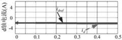
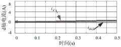
图8a至图8f为传统不带反馈矩阵的模型参考自适应方法和本发明的带反馈矩阵的自适应观测器方法在定子电阻参数不匹配下的转速和d、q轴电流波形图,可以发现当设定目标转速为800r/min,0.1s突加负载后,稳定运行0.1s后,0.2s到0.5s内,每隔0.1s定子电阻突增50%,可以看出传统控制方法下id,iq随着定子电阻参数变化,与给定电流值误差不断加大,直到电机失控,而所提控制方法下的id,iq仍然可以很好的跟踪其给定值,且误差随参数不匹配程度的增大,稳定在一定范围内。8a to 8f are the rotational speed and d and q axis current waveform diagrams of the traditional model reference adaptive method without feedback matrix and the adaptive observer method with feedback matrix of the present invention under the mismatch of stator resistance parameters. It can be found that When the target speed is set to 800r/min, after 0.1s sudden load is applied, after stable operation for 0.1s, within 0.2s to 0.5s, the stator resistance suddenly increases by 50% every0.1s , it can be seen that id under the traditional control method , iq with the change of stator resistance parameters, the error with the given current value keeps increasing until the motor is out of control, and under the proposed control methodid , iq can still track its given value very well, and the error increases with The parameter mismatch degree increases and stabilizes within a certain range.
图9a至图9f为传统不带反馈矩阵的模型参考自适应方法和本发明的带反馈矩阵的自适应观测器方法在电感参数不匹配下的转速和d、q轴电流波形图,可以发现当设定目标转速为800r/min,0.1s突加负载后,稳定运行0.1s后,0.2s到0.5s内,每隔0.1s电感突增50%,可以看出传统控制方法下id,iq随着电感参数变化,与给定电流值误差不断加大,尤其体现在id轴上,电机控制性能下降,而所提控制方法下的id,iq仍然可以很好的跟踪其给定值,且误差随参数不匹配程度的增大,稳定在一定范围内。9a to 9f are the rotational speed and d and q axis current waveform diagrams of the traditional model reference adaptive method without feedback matrix and the adaptive observer method with feedback matrix of the present invention under the mismatch of inductance parameters. It can be found that when The target speed is set to 800r/min, after 0.1s sudden load is applied, after 0.1s of stable operation, the inductance suddenly increases by 50% every 0.1s within 0.2s to 0.5s, it can be seen that under the traditional control methodid , i As the inductance parameter changes, the error betweenq and the given current value continues to increase, especially on theid axis, and the motor control performance decreases. However, theid and i qunder the proposed control method can still track the given current value very well. fixed value, and the error is stable within a certain range with the increase of the parameter mismatch.
图10a至图10f为传统不带反馈矩阵的模型参考自适应方法和本发明的带反馈矩阵的自适应观测器方法在转子磁链参数不配下的转速和d、q轴电流波形图,可以发现当设定目标转速为800r/min,0.1s时突加负载后,稳定运行0.1s后,0.2s到0.5s内,每隔0.1s转子磁链突增50%,可以看出传统控制方法下id,iq随着电感参数变化,与给定电流值误差不断加大,电机控制性能下降,电机转速波动,而所提控制方法下的id,iq仍然可以很好的跟踪其给定值,且误差随参数不匹配程度的增大,稳定在一定范围内,电机转速平滑。相对于传统的电流环比例积分控制器,解决了由于系统延时造成的相位滞后、动态性能受限问题。10a to 10f are the rotational speed and d and q axis current waveform diagrams of the traditional model reference adaptive method without feedback matrix and the adaptive observer method with feedback matrix of the present invention when the rotor flux linkage parameters are not matched. It can be found that When the target speed is set to 800r/min, the load is suddenly applied at 0.1s, and after 0.1s of stable operation, the rotor flux increases by 50% every 0.1s within 0.2s to 0.5s. It can be seen that under the traditional control method With the change of inductance parameters,id and iq keep increasing the error with the given current value, the control performance of the motor decreases, and the motor speed fluctuates. However, theid and i qof the proposed control method can still track the given current value very well. Fixed value, and the error increases with the degree of parameter mismatch, and is stable within a certain range, and the motor speed is smooth. Compared with the traditional current loop proportional-integral controller, it solves the problems of phase lag and limited dynamic performance caused by system delay.
综上所述,相对于传统基于定子电流的模型参考自适应法,本发明的带反馈矩阵的自适应观测器方法对电机参数敏感性降低,提升了系统鲁棒性。To sum up, compared with the traditional model reference adaptive method based on stator current, the adaptive observer method with feedback matrix of the present invention is less sensitive to motor parameters and improves the robustness of the system.
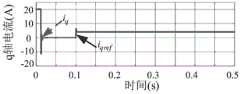
图11a至图11b为传统比例积分控制方法和本发明的自适应观测器方法在电流阶跃实验下的q轴指定电流iqref和实际电流iq的波形图,实验中iq,ref的幅值由0A阶跃到8A,综合考虑比例积分控制的动态响应和超调量,选择控制参数为:kp=2.5,ki=10,由图11a和图11b可以看出两种方法均能准确无误跟踪其给定值,但本发明的自适应观测器方法响应速度明显比传统比例积分控制提高至少50%,能够有效解决传统比例积分控制方法由于系统延时造成的相位滞后、动态性能受限问题。11a to 11b are the waveform diagrams of the q-axis specified current iqref and the actual current iq of the traditional proportional integral control method and the adaptive observer method of the present invention under the current step experiment, the amplitude of iq,ref in the experiment The value is stepped from 0A to 8A, considering the dynamic response and overshoot of proportional integral control, the control parameters are selected as: kp = 2.5, ki = 10, it can be seen from Figure 11a and Figure 11b that both methods can Accurately track its given value, but the response speed of the adaptive observer method of the present invention is obviously improved by at least 50% compared with the traditional proportional-integral control, which can effectively solve the phase lag and dynamic performance problems caused by the system delay caused by the traditional proportional-integral control method. limit problem.
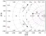
图12a、图12b、图13分别为采用本发明的自适应观测器在转速为900r/min以及额定转速3000r/min下的空载加速实验和额定转速3000r/min的突加额定负载实验下的实际转速、转子估计位置角
本发明的上述算例仅为详细地说明本发明的计算模型和计算流程,而并非是对本发明的实施方式的限定。对于所属领域的普通技术人员来说,在上述说明的基础上还可以做出其它不同形式的变化或变动,这里无法对所有的实施方式予以穷举,凡是属于本发明的技术方案所引伸出的显而易见的变化或变动仍处于本发明的保护范围之列。The above calculation examples of the present invention are only to illustrate the calculation model and calculation process of the present invention in detail, but are not intended to limit the embodiments of the present invention. For those of ordinary skill in the art, on the basis of the above description, other different forms of changes or changes can also be made, and it is impossible to list all the embodiments here. Obvious changes or modifications are still within the scope of the present invention.
Claims (5)
Translated fromChinese


Priority Applications (1)
| Application Number | Priority Date | Filing Date | Title |
|---|---|---|---|
| CN202110594014.0ACN113328672B (en) | 2021-05-28 | 2021-05-28 | Control method and system for dead-beat current prediction of permanent magnet motor without position sensor |
Applications Claiming Priority (1)
| Application Number | Priority Date | Filing Date | Title |
|---|---|---|---|
| CN202110594014.0ACN113328672B (en) | 2021-05-28 | 2021-05-28 | Control method and system for dead-beat current prediction of permanent magnet motor without position sensor |
Publications (2)
| Publication Number | Publication Date |
|---|---|
| CN113328672A CN113328672A (en) | 2021-08-31 |
| CN113328672Btrue CN113328672B (en) | 2022-02-15 |
Family
ID=77422261
Family Applications (1)
| Application Number | Title | Priority Date | Filing Date |
|---|---|---|---|
| CN202110594014.0AActiveCN113328672B (en) | 2021-05-28 | 2021-05-28 | Control method and system for dead-beat current prediction of permanent magnet motor without position sensor |
Country Status (1)
| Country | Link |
|---|---|
| CN (1) | CN113328672B (en) |
Families Citing this family (3)
| Publication number | Priority date | Publication date | Assignee | Title |
|---|---|---|---|---|
| CN114844420B (en)* | 2022-05-18 | 2025-01-03 | 南通长江电器实业有限公司 | A position sensorless control method for brushless DC motor based on model predictive control |
| CN115864928B (en)* | 2022-12-14 | 2025-08-01 | 安徽工业大学 | PMSM model reference self-adaptive rotating speed estimation method based on correction current prediction |
| CN117240049B (en)* | 2023-09-08 | 2024-03-19 | 东南大学 | Quick voltage response and transient state ride through control method and system for converter |
Citations (5)
| Publication number | Priority date | Publication date | Assignee | Title |
|---|---|---|---|---|
| US4663703A (en)* | 1985-10-02 | 1987-05-05 | Westinghouse Electric Corp. | Predictive model reference adaptive controller |
| CN106982017A (en)* | 2017-05-08 | 2017-07-25 | 哈尔滨工业大学 | A kind of induction machine Current Sensorless direct predictive control method |
| CN108832859A (en)* | 2018-04-26 | 2018-11-16 | 江苏大学 | A Predictive Current Control Method for Permanent Magnet Linear Motor Based on Parameter Identification |
| CN112003521A (en)* | 2020-07-13 | 2020-11-27 | 北京理工大学 | Surface-mounted permanent magnet synchronous motor current prediction control method |
| CN112350632A (en)* | 2020-10-12 | 2021-02-09 | 北京理工大学 | Current-free sensor prediction control method based on permanent magnet synchronous motor parameter identification |
- 2021
- 2021-05-28CNCN202110594014.0Apatent/CN113328672B/enactiveActive
Patent Citations (5)
| Publication number | Priority date | Publication date | Assignee | Title |
|---|---|---|---|---|
| US4663703A (en)* | 1985-10-02 | 1987-05-05 | Westinghouse Electric Corp. | Predictive model reference adaptive controller |
| CN106982017A (en)* | 2017-05-08 | 2017-07-25 | 哈尔滨工业大学 | A kind of induction machine Current Sensorless direct predictive control method |
| CN108832859A (en)* | 2018-04-26 | 2018-11-16 | 江苏大学 | A Predictive Current Control Method for Permanent Magnet Linear Motor Based on Parameter Identification |
| CN112003521A (en)* | 2020-07-13 | 2020-11-27 | 北京理工大学 | Surface-mounted permanent magnet synchronous motor current prediction control method |
| CN112350632A (en)* | 2020-10-12 | 2021-02-09 | 北京理工大学 | Current-free sensor prediction control method based on permanent magnet synchronous motor parameter identification |
Non-Patent Citations (4)
| Title |
|---|
| "感应电机高性能矢量控制及高速运行技术研究";王勃;《中国博士学位论文全文数据库工程科技II辑》;20190115;第18-27、37-48页* |
| "无速度传感器永磁同步电机预测电流控制策略";齐洪峰;《北京交通大学学报》;20200430;第44卷(第2期);第119-128页* |
| International Exhibition and Conference for Power Electronics, Intelligent Motion, Renewable Energy and Energy Management》.2017,第113-120页.* |
| Mohamed Abdelrahem等."A Robust Encoderless Predictive Current Control Using Novel MRAS Observer for Surface-Mounted Permanent-Magnet Synchronous Generators".《PCIM Europe 2017* |
Also Published As
| Publication number | Publication date |
|---|---|
| CN113328672A (en) | 2021-08-31 |
Similar Documents
| Publication | Publication Date | Title |
|---|---|---|
| CN113328672B (en) | Control method and system for dead-beat current prediction of permanent magnet motor without position sensor | |
| KR100423715B1 (en) | Synchronous motor control device and method | |
| CN110022105A (en) | Permanent magnet synchronous motor predictive-current control method and system based on FOSMC | |
| Xu et al. | Transient response characteristics improvement of permanent magnet synchronous motor based on enhanced linear active disturbance rejection sensorless control | |
| CN112422004B (en) | Disturbance suppression method for permanent magnet synchronous motor in weak magnetic control mode | |
| CN107046387A (en) | A kind of change pid parameter electric current loop of permagnetic synchronous motor starts method | |
| Kim | Model reference adaptive control-based adaptive current control scheme of a PM synchronous motor with an improved servo performance | |
| CN116526919A (en) | Permanent magnet synchronous motor servo system and current prediction control method and device thereof | |
| Pei et al. | Predictive current trajectory control for PMSM at voltage limit | |
| CN108964556A (en) | For driving the senseless control device of permanent magnetic synchronous electrical motor | |
| Vyncke et al. | Direct torque control of permanent magnet synchronous motors–an overview | |
| CN110011587A (en) | A sensorless vector control method for permanent magnet synchronous motor based on multi-parameter identification | |
| Ren et al. | A vector control system of PMSM with the assistance of fuzzy PID controller | |
| Jevremovic et al. | Speed-sensorless control of induction motor based on reactive power with rotor time constant identification | |
| Rubino et al. | Deadbeat direct flux vector control of surface permanent magnet motor drives | |
| Zhang et al. | Indirect field-oriented control of induction machines based on synergetic control theory | |
| Jukić et al. | Framework for sensorless control and flying start of a permanent magnet generator based on a sliding mode observer | |
| Dwivedi et al. | Review on control strategies of permanent magnet-assisted synchronous reluctance motor drive | |
| Sahu et al. | Adaptive fuzzy sliding mode based torque and speed compensator for DTC IM drive | |
| CN119109366A (en) | Motor torque ripple suppression method based on integral proportional and quasi-proportional resonant control | |
| Singh et al. | Sensor-based and sensorless vector control of PM synchronous motor drives: a comparative study | |
| Hu et al. | Current sensorless direct predictive control for permanent-magnet synchronous motor drives | |
| CN117997199A (en) | Torque fluctuation suppression method and system for permanent magnet synchronous motor | |
| Moldovan et al. | Active-flux-based, V/f-with-stabilizing-loops versus sensorless vector control of IPMSM Drives | |
| CN115378325B (en) | Direct speed composite control method for SMPMSM drive system based on dynamic weight factor |
Legal Events
| Date | Code | Title | Description |
|---|---|---|---|
| PB01 | Publication | ||
| PB01 | Publication | ||
| SE01 | Entry into force of request for substantive examination | ||
| SE01 | Entry into force of request for substantive examination | ||
| GR01 | Patent grant | ||
| GR01 | Patent grant |