CN113320542B - A tracking control method for an autonomous vehicle - Google Patents
A tracking control method for an autonomous vehicleDownload PDFInfo
- Publication number
- CN113320542B CN113320542BCN202110703645.1ACN202110703645ACN113320542BCN 113320542 BCN113320542 BCN 113320542BCN 202110703645 ACN202110703645 ACN 202110703645ACN 113320542 BCN113320542 BCN 113320542B
- Authority
- CN
- China
- Prior art keywords
- vehicle
- control
- path
- constraint
- tracking
- Prior art date
- Legal status (The legal status is an assumption and is not a legal conclusion. Google has not performed a legal analysis and makes no representation as to the accuracy of the status listed.)
- Active
Links
- 238000000034methodMethods0.000titleclaimsabstractdescription64
- 230000008569processEffects0.000claimsabstractdescription34
- 238000005457optimizationMethods0.000claimsdescription18
- 230000001133accelerationEffects0.000claimsdescription17
- 239000011159matrix materialSubstances0.000claimsdescription12
- 238000012360testing methodMethods0.000claimsdescription10
- 238000006073displacement reactionMethods0.000claimsdescription4
- 230000008859changeEffects0.000claimsdescription3
- 238000013016dampingMethods0.000claimsdescription3
- 230000005484gravityEffects0.000claimsdescription3
- 230000002265preventionEffects0.000claimsdescription3
- 238000005070samplingMethods0.000claimsdescription3
- 230000001052transient effectEffects0.000claimsdescription3
- 239000007983Tris bufferSubstances0.000claims1
- 230000010429evolutionary processEffects0.000claims1
- 230000008846dynamic interplayEffects0.000abstract1
- 230000006870functionEffects0.000description10
- 230000035772mutationEffects0.000description7
- 238000013461designMethods0.000description6
- 238000010586diagramMethods0.000description4
- 238000012546transferMethods0.000description4
- 230000000694effectsEffects0.000description3
- 230000003993interactionEffects0.000description3
- 230000009286beneficial effectEffects0.000description2
- 230000008878couplingEffects0.000description2
- 238000010168coupling processMethods0.000description2
- 238000005859coupling reactionMethods0.000description2
- 238000005516engineering processMethods0.000description2
- 230000010355oscillationEffects0.000description2
- 230000004044responseEffects0.000description2
- 206010039203Road traffic accidentDiseases0.000description1
- 230000003044adaptive effectEffects0.000description1
- 238000013528artificial neural networkMethods0.000description1
- 230000003190augmentative effectEffects0.000description1
- 230000007547defectEffects0.000description1
- 230000007613environmental effectEffects0.000description1
- 239000000446fuelSubstances0.000description1
- 230000004048modificationEffects0.000description1
- 238000012986modificationMethods0.000description1
- 238000005312nonlinear dynamicMethods0.000description1
- 230000008447perceptionEffects0.000description1
- 238000011160researchMethods0.000description1
- 238000005096rolling processMethods0.000description1
- 238000006467substitution reactionMethods0.000description1
- 230000007704transitionEffects0.000description1
- 238000009827uniform distributionMethods0.000description1
Images


Classifications
- B—PERFORMING OPERATIONS; TRANSPORTING
- B60—VEHICLES IN GENERAL
- B60W—CONJOINT CONTROL OF VEHICLE SUB-UNITS OF DIFFERENT TYPE OR DIFFERENT FUNCTION; CONTROL SYSTEMS SPECIALLY ADAPTED FOR HYBRID VEHICLES; ROAD VEHICLE DRIVE CONTROL SYSTEMS FOR PURPOSES NOT RELATED TO THE CONTROL OF A PARTICULAR SUB-UNIT
- B60W60/00—Drive control systems specially adapted for autonomous road vehicles
- B60W60/001—Planning or execution of driving tasks
- B—PERFORMING OPERATIONS; TRANSPORTING
- B60—VEHICLES IN GENERAL
- B60W—CONJOINT CONTROL OF VEHICLE SUB-UNITS OF DIFFERENT TYPE OR DIFFERENT FUNCTION; CONTROL SYSTEMS SPECIALLY ADAPTED FOR HYBRID VEHICLES; ROAD VEHICLE DRIVE CONTROL SYSTEMS FOR PURPOSES NOT RELATED TO THE CONTROL OF A PARTICULAR SUB-UNIT
- B60W10/00—Conjoint control of vehicle sub-units of different type or different function
- B60W10/20—Conjoint control of vehicle sub-units of different type or different function including control of steering systems
- B—PERFORMING OPERATIONS; TRANSPORTING
- B60—VEHICLES IN GENERAL
- B60W—CONJOINT CONTROL OF VEHICLE SUB-UNITS OF DIFFERENT TYPE OR DIFFERENT FUNCTION; CONTROL SYSTEMS SPECIALLY ADAPTED FOR HYBRID VEHICLES; ROAD VEHICLE DRIVE CONTROL SYSTEMS FOR PURPOSES NOT RELATED TO THE CONTROL OF A PARTICULAR SUB-UNIT
- B60W30/00—Purposes of road vehicle drive control systems not related to the control of a particular sub-unit, e.g. of systems using conjoint control of vehicle sub-units
- B60W30/02—Control of vehicle driving stability
- B60W30/04—Control of vehicle driving stability related to roll-over prevention
- B60W2030/043—Control of vehicle driving stability related to roll-over prevention about the roll axis
- B—PERFORMING OPERATIONS; TRANSPORTING
- B60—VEHICLES IN GENERAL
- B60W—CONJOINT CONTROL OF VEHICLE SUB-UNITS OF DIFFERENT TYPE OR DIFFERENT FUNCTION; CONTROL SYSTEMS SPECIALLY ADAPTED FOR HYBRID VEHICLES; ROAD VEHICLE DRIVE CONTROL SYSTEMS FOR PURPOSES NOT RELATED TO THE CONTROL OF A PARTICULAR SUB-UNIT
- B60W40/00—Estimation or calculation of non-directly measurable driving parameters for road vehicle drive control systems not related to the control of a particular sub unit, e.g. by using mathematical models
- B60W40/02—Estimation or calculation of non-directly measurable driving parameters for road vehicle drive control systems not related to the control of a particular sub unit, e.g. by using mathematical models related to ambient conditions
- B60W40/06—Road conditions
- B60W40/072—Curvature of the road
- B—PERFORMING OPERATIONS; TRANSPORTING
- B60—VEHICLES IN GENERAL
- B60W—CONJOINT CONTROL OF VEHICLE SUB-UNITS OF DIFFERENT TYPE OR DIFFERENT FUNCTION; CONTROL SYSTEMS SPECIALLY ADAPTED FOR HYBRID VEHICLES; ROAD VEHICLE DRIVE CONTROL SYSTEMS FOR PURPOSES NOT RELATED TO THE CONTROL OF A PARTICULAR SUB-UNIT
- B60W40/00—Estimation or calculation of non-directly measurable driving parameters for road vehicle drive control systems not related to the control of a particular sub unit, e.g. by using mathematical models
- B60W40/02—Estimation or calculation of non-directly measurable driving parameters for road vehicle drive control systems not related to the control of a particular sub unit, e.g. by using mathematical models related to ambient conditions
- B60W40/06—Road conditions
- B60W40/076—Slope angle of the road
- Y—GENERAL TAGGING OF NEW TECHNOLOGICAL DEVELOPMENTS; GENERAL TAGGING OF CROSS-SECTIONAL TECHNOLOGIES SPANNING OVER SEVERAL SECTIONS OF THE IPC; TECHNICAL SUBJECTS COVERED BY FORMER USPC CROSS-REFERENCE ART COLLECTIONS [XRACs] AND DIGESTS
- Y02—TECHNOLOGIES OR APPLICATIONS FOR MITIGATION OR ADAPTATION AGAINST CLIMATE CHANGE
- Y02T—CLIMATE CHANGE MITIGATION TECHNOLOGIES RELATED TO TRANSPORTATION
- Y02T10/00—Road transport of goods or passengers
- Y02T10/10—Internal combustion engine [ICE] based vehicles
- Y02T10/40—Engine management systems
Landscapes
- Engineering & Computer Science (AREA)
- Transportation (AREA)
- Mechanical Engineering (AREA)
- Automation & Control Theory (AREA)
- Human Computer Interaction (AREA)
- Chemical & Material Sciences (AREA)
- Combustion & Propulsion (AREA)
- Control Of Driving Devices And Active Controlling Of Vehicle (AREA)
- Steering Control In Accordance With Driving Conditions (AREA)
Abstract
Translated fromChinese
Description
Translated fromChinese技术领域technical field
本发明涉及自动驾驶车辆运动控制领域,特别是指一种自动驾驶车辆的跟踪控制方法。The invention relates to the field of automatic driving vehicle motion control, in particular to a tracking control method of the automatic driving vehicle.
背景技术Background technique
自动驾驶车辆具有驾驶行为可预测、减少交通事故发生及缓解交通压力等优点,在未来智能交通系统和军事领域中拥有广阔的应用前景。经过几十年的研究和试验,自动驾驶技术从辅助驾驶不断向全自动驾驶过渡完善。全自动驾驶车辆从上至下需要构建地图定位、环境感知与决策、运动控制等关键技术。路径跟踪是执行运动控制层的关键功能部分,直接决定了自动驾驶车辆的整体性能表现。路径跟踪控制是研究如何根据运动规划和车辆行驶状态反馈信息,在考虑行驶安全性和乘坐舒适性的前提下控制转向执行器动作沿理想车道路径行驶。在路径跟踪控制中很难同时保证其跟踪精度和行驶稳定性,考虑车辆与道路动态信息之间进一步的集成交互可以有效地提高自动驾驶车辆在不同行驶条件下的路径跟踪性能。Self-driving vehicles have the advantages of predictable driving behavior, reducing traffic accidents and alleviating traffic pressure, and have broad application prospects in future intelligent transportation systems and military fields. After decades of research and experimentation, autonomous driving technology has continued to transition from assisted driving to fully autonomous driving. From top to bottom, fully autonomous vehicles need to build key technologies such as map positioning, environmental perception and decision-making, and motion control. Path tracking is a key functional part of executing the motion control layer, which directly determines the overall performance of the autonomous vehicle. Path tracking control is to study how to control the steering actuator to drive along the ideal lane path under the premise of considering the driving safety and riding comfort according to the motion planning and the feedback information of the vehicle driving state. In path tracking control, it is difficult to ensure its tracking accuracy and driving stability at the same time. Considering the further integrated interaction between vehicle and road dynamic information can effectively improve the path tracking performance of autonomous vehicles under different driving conditions.
车辆本身高度动态的非线性特性和耦合性以及易受外部扰动的影响,使得实现自动驾驶车辆的准确路径跟踪控制存在一定挑战。目前,许多经典的控制方法已经被广泛应用于路径跟踪,主要可分为以下几类:1)几何运动控制,主要为纯轨迹跟踪、Stanley控制等;2)无模型控制,主要为PID控制、模糊控制、神经网络控制等;3)状态反馈控制,主要为LQG控制、滑模控制、H∞鲁棒控制等;上述方法不能有效地考虑车辆和道路的约束,将会导致执行器饱和甚至动力学不稳定。4)模型预测控制,模型预测控制方法可以预测未来非线性系统的多步输出行为,通过滚动求解约束最优目标问题来控制修正系统的跟随误差。由于模型预测控制能够显式地解决复杂动态环境下多输入多输出系统的多约束问题,已被广泛应用于自动驾驶车辆的路径跟踪。The highly dynamic nonlinear characteristics and coupling of the vehicle itself and its vulnerability to external disturbances make it challenging to achieve accurate path tracking control of autonomous vehicles. At present, many classical control methods have been widely used in path tracking, which can be mainly divided into the following categories: 1) geometric motion control, mainly pure trajectory tracking, Stanley control, etc.; 2) model-free control, mainly PID control, Fuzzy control, neural network control, etc.; 3) State feedback control, mainly LQG control, sliding mode control, H∞ robust control, etc. The above methods cannot effectively consider the constraints of vehicles and roads, which will lead to actuator saturation and even power Learning is unstable. 4) Model predictive control, the model predictive control method can predict the multi-step output behavior of the future nonlinear system, and control and correct the following error of the system by rolling the solution of the constrained optimal target problem. Since model predictive control can explicitly solve the multi-constraint problem of MIMO systems in complex dynamic environments, it has been widely used in path tracking of autonomous vehicles.
在现有路径跟踪问题中一般通过最小化侧向误差与航向误差对道路中心线进行严格跟踪,或者通过两个独立控制器分别解决路径规划与跟踪问题。然而,从道路中心线或路径规划中获得的参考路径通常不够平滑,甚至与车辆运动特性存在冲突,以上方法普遍缺乏考虑车辆与道路动态信息之间的相互影响,直接跟随该参考路径容易导致响应超调、振荡等不稳定现象。In the existing path tracking problem, the road centerline is generally strictly tracked by minimizing the lateral error and heading error, or the path planning and tracking problems are solved by two independent controllers. However, the reference path obtained from the road centerline or path planning is usually not smooth enough, and even conflicts with the vehicle motion characteristics. The above methods generally lack consideration of the interaction between the vehicle and road dynamic information, and directly following the reference path will easily lead to response Unstable phenomena such as overshoot and oscillation.
发明内容SUMMARY OF THE INVENTION
本发明的主要目的在于克服路径跟踪问题中的上述缺陷,提出一种自动驾驶车辆的跟踪控制方法。The main purpose of the present invention is to overcome the above-mentioned defects in the path tracking problem, and propose a tracking control method for an automatic driving vehicle.
本发明采用如下技术方案:The present invention adopts following technical scheme:
一种自动驾驶车辆的跟踪控制方法,其特征在于,预先建立考虑道路倾角与曲率的车辆动力学模型,控制方法包括如下步骤:A tracking control method for an autonomous vehicle, characterized in that a vehicle dynamics model considering road inclination and curvature is established in advance, and the control method comprises the following steps:
1)基于车辆动力学模型构建当前时刻的动态预测过程,并设计考虑驾驶路径信息的扩展模型预测控制器;1) Build the dynamic prediction process at the current moment based on the vehicle dynamics model, and design an extended model predictive controller that considers the driving path information;
2)通过车辆动力学模型获取当前时刻车辆的状态信息,根据状态信息建立约束包络,包括防滑移约束、防侧翻约束、可行驶道路区域约束和扩展模型预测控制器约束;2) Obtain the state information of the vehicle at the current moment through the vehicle dynamics model, and establish a constraint envelope according to the state information, including the anti-slip constraint, the anti-rollover constraint, the drivable road area constraint and the extended model predictive controller constraint;
3)根据动态预测过程和约束包络利用差分进化算法求解得到当前时刻的最优控制转向角,扩展模型预测控制器根据最优控制转向角控制车辆在可行驶道路区域内自主跟踪最优的平滑路径;3) According to the dynamic prediction process and the constraint envelope, the optimal control steering angle at the current moment is obtained by using the differential evolution algorithm, and the extended model predictive controller controls the vehicle to autonomously track the optimal smoothness in the drivable road area according to the optimal control steering angle. path;
4)回到步骤1)计算下一个控制周期的最优控制转向角,直到车辆到达路径的终点。4) Go back to step 1) to calculate the optimal control steering angle for the next control cycle until the vehicle reaches the end of the path.
所述车辆动力学模型的三自由度动力学模型,具体如下:The three-degree-of-freedom dynamic model of the vehicle dynamics model is specifically as follows:

其中,m与ms分别为车辆质量与簧载质量;g为重力加速度;lf与lr分别为车辆质心到前、后轴的距离;Ix与Iz分别为侧倾与横摆转动惯量;


对轮胎模型进行线性化建模为:Linearize the tire model as:
Fyf=-Cfαf,Fyr=-CrαrFyf =-Cf αf ,Fyr =-Cr αr
其中,Cf与Cr分别为前、后轮侧偏刚度;αf与αr分别为前、后轮侧偏角,在小角度假设下被表示为:Among them, Cf and Cr are the front and rear wheel cornering stiffness, respectively; αf and αr are the front and rear wheel side slip angles, respectively, which are expressed as:

其中,δf为前轮转角。Among them, δf is the front wheel rotation angle.
以


其中,Ac、Buc与Bvc分别为状态变量、控制输入与干扰输入的系数矩阵;Cc为跟踪误差输出的系数矩阵。Among them, Ac , Buc and Bvc are the coefficient matrix of state variables, control input and disturbance input respectively; Cc is the coefficient matrix of tracking error output.
所述基于车辆动力学模型构建当前时刻的动态预测过程具体为:采用采样时间Ts对车辆动力学模型的状态空间系统进行离散化得到离散状态空间模型,再引入增量形式来减小控制误差;通过当前状态ξ(k)、控制增量序列ΔUc(k)与外部干扰γ(k)能够得到描述状态空间系统未来输出行为的动态预测过程为:The dynamic prediction process of constructing the current moment based on the vehicle dynamics model is specifically as follows: using the sampling time Ts to discretize the state space system of the vehicle dynamics model to obtain a discrete state space model, and then introducing an incremental form to reduce the control error ; Through the current state ξ(k), the control increment sequence ΔUc (k) and the external disturbance γ(k), the dynamic prediction process describing the future output behavior of the state-space system can be obtained as follows:


其中,


所述设计考虑驾驶路径信息的扩展模型预测控制器,通过参考路径规划来优化指标,得到考虑最短跟踪路径、最优路径曲率与路径航向跟随的目标优化函数为:The extended model predictive controller that considers the driving path information is designed, and the index is optimized by referring to the path planning, and the objective optimization function considering the shortest tracking path, the optimal path curvature and the path heading following is obtained as follows:

其中,Np为预测时域;Nc为控制时域;ρ(k+i)是在时刻k的行驶路径曲率;S(k+i)是在时刻k的行驶路径长度;Гk、Гs、Гψ与Гu是相对应的权重因子。Among them, Np is the prediction time domain; Nc is the control time domain; ρ(k+i) is the travel path curvature at time k; S(k+i) is the travel path length at time k; Гk , Гs , Гψ and Гu are the corresponding weighting factors.
给定全局车辆姿态(x0,y0,ts)作为时间步长内的瞬态变量,通过动态预测过程解析求解预测步长内相应的行驶路径曲率和长度,在预测过程与目标函数之间添加中间变量为:Given the global vehicle attitude (x0 , y0 , ts ) as the transient variables in the time step, the corresponding driving path curvature and length in the prediction step are analytically solved through the dynamic prediction process. Add intermediate variables as:


eψ(k+i)=ψ(k+i)-ψref(k+i)。eψ (k+i)=ψ(k+i)−ψref (k+i).
其中,

所述防滑移约束通过对轮胎侧偏角施加约束条件为:The anti-slip constraint imposes constraints on the tire slip angle as follows:

其中,αt为轮胎约束角;以及设定横摆角速度约束为:where αt is the tire constraint angle; and the yaw rate constraint is set as:

所述防侧翻约束将横向载荷转移率LTRd等效表示为:The anti-rollover constraint is equivalently expressed as the lateral load transfer rate LTRd as:

其中,Tr为轮距;则防侧翻约束表示为:Among them, Tr is the wheelbase; then the anti-rollover constraint is expressed as:
-LTRdmax≤LTRd≤LTRdmax-LTRdmax ≤LTRd ≤LTRdmax
其中,LTRdmax为侧翻阈值。where LTRdmax is the rollover threshold.
结合车辆的侧向与纵向包络范围,可行驶道路区域约束表示为:Combined with the lateral and longitudinal envelope of the vehicle, the drivable road area constraint is expressed as:
Envmin≤eyk≤EnvmaxEnvmin ≤eyk ≤Envmax
其中,


扩展模型预测控制器约束将每个步长内的控制输入、控制增量和预测输出的各种约束工况表示为:The extended model predictive controller constraints express the various constraint cases of control input, control increment, and predicted output within each step as:
△umin(k+i)≤△u(k+i)≤△umax(k+i)△umin (k+i)≤△u(k+i)≤△umax (k+i)
i=0,1,…,Nc-1i=0,1,...,Nc -1
umin(k+i)≤u(k+i)≤umax(k+i)umin (k+i)≤u(k+i)≤umax (k+i)
i=0,1,…,Nc-1i=0,1,...,Nc -1
ymin(k+i)≤y(k+i)≤ymax(k+i)ymin (k+i)≤y(k+i)≤ymax (k+i)
i=1,2,…,Npi= 1,2,...,Np
其中,△umin(k+i)与△umax(k+i)分别为控制增量的上下限;umin(k+i)与umax(k+i)分别为控制输入的上下限;ymin(k+i)与ymax(k+i)分别为状态空间系统输出的上下限。Among them, Δumin (k+i) and Δumax (k+i) are the upper and lower limits of the control increment, respectively; umin (k+i) and umax (k+i) are the upper and lower limits of the control input, respectively ; ymin (k+i) and ymax (k+i) are the upper and lower limits of the state-space system output, respectively.
步骤3)具体包括如下:Step 3) specifically includes the following:
3.1)将前轮转角控制增量设为优化变量,并在约束范围内随机生成控制增量的初始种群;3.1) Set the front wheel rotation angle control increment as the optimization variable, and randomly generate the initial population of the control increment within the constraint range;
3.2)通过获得控制时域内的初始种群来计算预测时域内的行驶路径曲率、长度与航向误差,将考虑多约束的目标优化函数Je设为主适应度函数,记录每个更新种群对应的目标适应度函数值;3.2) Calculate the travel path curvature, length and heading error in the prediction time domain by obtaining the initial population in the control time domain, set the objective optimization function Je considering multiple constraints as the main fitness function, and record the target corresponding to each updated population fitness function value;
3.3)通过对两个不同的随机目标控制输入执行相减生成一个差分变量,并通过更新差分变量在搜索空间中的变异和交叉操作来生成新的试验个体;3.3) Generate a differential variable by performing subtraction of two different random target control inputs, and generate new test individuals by updating the mutation and crossover operations of the differential variable in the search space;
3.4)通过评估更新后种群的适应度值进行选择操作;当更新后的试验种群适应度值小于上一代目标种群适应度值时,选择试验种群作为下一代种群;进化过程将重复固定的迭代寻优或在搜索过程中达到给定的精度收敛时结束,得到最优控制转向角序列求解优化问题。3.4) The selection operation is performed by evaluating the fitness value of the updated population; when the fitness value of the updated test population is less than the fitness value of the target population of the previous generation, the test population is selected as the next generation population; the evolution process will repeat a fixed iterative search. It ends when the search process reaches a given precision and converges, and the optimal control steering angle sequence is obtained to solve the optimization problem.
由上述对本发明的描述可知,与现有技术相比,本发明具有如下有益效果:As can be seen from the above description of the present invention, compared with the prior art, the present invention has the following beneficial effects:
(1)为了更好地考虑道路动态信息,本发明在路径跟踪过程中将道路倾角与曲率作为外部干扰输入,建立包含车辆侧向、横摆与侧倾自由度的车辆动力学模型,提高对车辆未来状态的预测准确度,进一步提升路径跟踪的控制精度。(1) In order to better consider the road dynamic information, the present invention uses the road inclination and curvature as external disturbance inputs during the path tracking process, and establishes a vehicle dynamics model including the vehicle lateral, yaw and roll degrees of freedom to improve the accuracy of the vehicle. The prediction accuracy of the future state of the vehicle further improves the control accuracy of path tracking.
(2)结合车辆与道路动态信息,本发明设计了考虑行驶路径信息的扩展模型预测控制方法,同时推导并施加了防侧翻约束与行驶道路包络等约束,通过差分进化算法对引入扩展变量过程的路径跟踪优化问题进行求解,有效结合路径规划与跟踪控制,获得理想的跟踪路径。(2) Combined with vehicle and road dynamic information, the present invention designs an extended model predictive control method considering driving path information, and at the same time derives and imposes constraints such as rollover prevention constraints and driving road envelopes, and introduces extended variables through differential evolution algorithm. The path tracking optimization problem of the process is solved, and the ideal tracking path is obtained by effectively combining path planning and tracking control.
(3)本发明方法,能够充分利用自动驾驶车辆的机动性,实现在可行驶道路区域内的最优平滑路径跟踪,提高了转弯过程的路径跟踪质量,有利于改善车辆的驾驶舒适性和道路利用率。(3) The method of the present invention can make full use of the mobility of the self-driving vehicle, realize the optimal smooth path tracking in the drivable road area, improve the path tracking quality in the turning process, and help improve the driving comfort of the vehicle and the road utilization.
附图说明Description of drawings
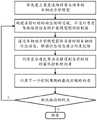
图1是本发明方法流程图。Fig. 1 is the flow chart of the method of the present invention.
图2是本发明的考虑道路倾角的车辆动力学模型示意图一。FIG. 2 is a schematic diagram 1 of the vehicle dynamics model considering the road inclination according to the present invention.
图3是本发明的考虑道路倾角的车辆动力学模型示意图二。FIG. 3 is a second schematic diagram of the vehicle dynamics model considering the road inclination according to the present invention.
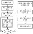
图4是本发明路径跟踪优化问题的差分进化算法求解过程示意图。FIG. 4 is a schematic diagram of the solution process of the differential evolution algorithm for the path tracking optimization problem of the present invention.
图5是本发明的自动驾驶车辆路径跟踪效果对比示意图。FIG. 5 is a schematic diagram showing the comparison of the path tracking effects of the automatic driving vehicle of the present invention.
以下结合附图和具体实施例对本发明作进一步详述。The present invention will be described in further detail below with reference to the accompanying drawings and specific embodiments.
具体实施方式Detailed ways
以下通过具体实施方式对本发明作进一步的描述。The present invention will be further described below through specific embodiments.
一种自动驾驶车辆的跟踪控制方法,为了提高自动驾驶车辆在高速及复杂道路行驶下的可靠性,有必要在车辆模型中进一步准确描述横向与侧倾动力学特性,从而实现更为精确的系统未来状态预测与约束性能设计,因此,预先建立考虑道路倾角与曲率的车辆动力学模型。本发明考虑车辆行驶道路的倾角与曲率干扰,并增加车辆的侧倾自由度,建立一个三自由度的车辆动力学模型,如图2与图3所示,具体如下:A tracking control method for autonomous vehicles. In order to improve the reliability of autonomous vehicles in high-speed and complex road driving, it is necessary to further accurately describe the lateral and roll dynamics in the vehicle model, so as to achieve a more accurate system in the future. State prediction and constraint performance design, therefore, a vehicle dynamics model that takes into account road inclination and curvature is established in advance. The present invention considers the inclination and curvature interference of the road where the vehicle travels, and increases the roll degree of freedom of the vehicle to establish a vehicle dynamics model with three degrees of freedom, as shown in Figure 2 and Figure 3, as follows:

其中,m与ms分别为车辆质量与簧载质量;g为重力加速度;lf与lr分别为车辆质心到前、后轴的距离;Ix与Iz分别为侧倾与横摆转动惯量;


车辆的非线性动力学特性主要来源于轮胎侧向力,对轮胎模型进行线性化建模为:The nonlinear dynamic characteristics of the vehicle mainly come from the lateral force of the tire, and the linearized modeling of the tire model is as follows:
Fyf=-Cfαf,Fyr=-CrαrFyf =-Cf αf ,Fyr =-Cr αr
其中,Cf与Cr分别为前、后轮侧偏刚度;αf与αr分别为前、后轮侧偏角,在小角度假设下被表示为:Among them, Cf and Cr are the front and rear wheel cornering stiffness, respectively; αf and αr are the front and rear wheel side slip angles, respectively, which are expressed as:

其中,δf为前轮转角。Among them, δf is the front wheel rotation angle.
以


其中,Ac、Buc与Bvc分别为状态变量、控制输入与干扰输入的系数矩阵;Cc为跟踪误差输出的系数矩阵。Among them, Ac , Buc and Bvc are the coefficient matrix of state variables, control input and disturbance input respectively; Cc is the coefficient matrix of tracking error output.
至此,建立了一个考虑侧向与侧倾动态的车辆动力学系统模型,主要考虑了道路侧倾变化对系统的影响。So far, a vehicle dynamics system model considering lateral and roll dynamics has been established, mainly considering the influence of road roll changes on the system.
参见图1,本发明的控制方法包括如下步骤:Referring to Fig. 1, the control method of the present invention comprises the following steps:
1)基于车辆动力学模型构建当前时刻的动态预测过程,并设计考虑驾驶路径信息的扩展模型预测控制器。1) Build the dynamic prediction process at the current moment based on the vehicle dynamics model, and design an extended model predictive controller that considers the driving path information.
具体为:为了预测未来一段时间系统的输出,采用采样时间Ts对车辆动力学模型的状态空间系统进行离散化:Specifically: In order to predict the output of the system for a period of time in the future, the sampling time Ts is used to discretize the state space system of the vehicle dynamics model:


得到离散状态空间模型:Get the discrete state space model:
x(k+1)=Adx(k)+Budu(k)+Bvdγ(k)x(k+1)=Ad x(k)+Bud u(k)+Bvd γ(k)
y(k)=Cdx(k)y(k)=Cd x(k)
其中,Cd=Cc。where Cd =Cc .
为了提高控制输入的准确执行与约束,引入增量形式Δu来减小控制误差,从而获得:In order to improve the accurate execution and constraints of the control input, an incremental form Δu is introduced to reduce the control error, thereby obtaining:
ξ(k+1)=Aξ(k)+Bu△u(k)+Bvγ(k)ξ(k+1)=Aξ(k)+Bu △u(k)+Bv γ(k)
y(k)=Cξ(k)y(k)=Cξ(k)
其中,增广状态向量
定义预测时域为Np,控制时域为Nc(Nc<Np),通过测量或估计状态变量ξ(k)来动态获取当前车辆状态。根据k时刻的当前车辆状态,在k+1至k+Np时刻的未来车辆状态可以预测得到:The prediction time domain is defined as Np , and the control time domain is defined as Nc (Nc <Np ), and the current vehicle state is dynamically obtained by measuring or estimating the state variable ξ(k). According to the current vehicle state at time k, the future vehicle state at time k+1 to k+Np can be predicted as follows:
ξ(k+1)=Aξ(k)+Bu△u(k)+Bvγ(k)ξ(k+1)=Aξ(k)+Bu △u(k)+Bv γ(k)
ξ(k+2)=A2ξ(k)+ABu△u(k)+Bu△u(k+1)+ABvγ(k)+Bvγ(k)ξ(k+2)=A2 ξ(k)+ABu △u(k)+Bu △u(k+1)+ABv γ(k)+Bv γ(k)


当控制范围超过Nc时域步长之后,控制输入将保持不变。通过使用逐次替换Δu(k+Nc)=Δu(k+Nc+1)=…=Δu(k+Np-1)=0,使得u(k+Nc-1)=u(k+Nc)=…=u(k+Np-1)。通过上式计算得到k+1至k+Np时刻的未来车辆输出为:When the control range exceeds theNc time domain step size, the control input will remain unchanged. By using successive substitutions Δu(k+Nc -1)=Δu(k+Nc +1)=...=Δu(k+Np -1)=0, such that u(k+Nc -1)=u(k +Nc )=...=u(k +Np-1). The future vehicle output from time k+1 to k+Np calculated by the above formula is:
y(k+1)=CAξ(k)+CBu△u(k)+CBvγ(k)y(k+1)=CAξ(k)+CBu △u(k)+CBv γ(k)
y(k+2)=CA2ξ(k)+CABu△u(k)+CBu△u(k+1)+CABvγ(k)+CBvγ(k)y(k+2)=CA2 ξ(k)+CABu △u(k)+CBu △u(k+1)+CABv γ(k)+CBv γ(k)


在预测时域Np与控制时域为Nc内的预测序列表示为:The prediction sequence in the prediction time domain Np and the control time domain Nc is expressed as:

其中,Xp(k)为在时刻k的状态预测序列;Yp(k)为在时刻k的输出预测序列;ΔUc(k)为在时刻k的控制序列。Among them, Xp (k) is the state prediction sequence at time k; Yp (k) is the output prediction sequence at time k; ΔUc (k) is the control sequence at time k.
因此,通过当前状态ξ(k)、控制增量序列ΔUc(k)与外部干扰γ(k)能够得到描述状态空间系统未来输出行为的动态预测过程为:Therefore, through the current state ξ(k), the control increment sequence ΔUc (k) and the external disturbance γ(k), the dynamic prediction process describing the future output behavior of the state space system can be obtained as follows:


其中,


其中,

为了实现自动驾驶车辆在可行驶道路区域内平滑跟踪最优行驶路径,进一步提升路径跟踪的稳定性和舒适性,本发明通过参考路径规划来优化以下指标:(1)最短跟踪路径,即行驶路径长度尽可能缩短,达到降低行驶时间和油耗的目的;(2)最优路径曲率,即最小化行驶路径曲率以获得平滑的路径跟踪性能,同时避免大曲率转弯发生车辆侧滑或侧翻;(3)路径航向跟随,即使跟踪路径的航向与道路中心线基本保持一致,从而保证准确的路径航向。因此,设计考虑驾驶路径信息的扩展模型预测控制器,通过参考路径规划来优化指标,得到考虑最短跟踪路径、最优路径曲率与路径航向跟随的目标优化函数为:In order to realize the automatic driving vehicle smoothly track the optimal driving path in the drivable road area and further improve the stability and comfort of the path tracking, the present invention optimizes the following indicators by referring to the path planning: (1) the shortest tracking path, that is, the driving path The length should be shortened as much as possible to achieve the purpose of reducing driving time and fuel consumption; (2) Optimal path curvature, that is, minimizing the curvature of the driving path to obtain smooth path tracking performance, while avoiding vehicle sideslip or rollover in turns with large curvature; ( 3) Follow the path heading, even if the heading of the tracked path is basically consistent with the road centerline, so as to ensure the accurate path heading. Therefore, an extended model predictive controller considering the driving path information is designed, and the index is optimized by referring to the path planning, and the objective optimization function considering the shortest tracking path, the optimal path curvature and the path heading following is obtained as:

其中,Np为预测时域;Nc为控制时域;ρ(k+i)是在时刻k的行驶路径曲率;S(k+i)是在时刻k的行驶路径长度;Гk、Гs、Гψ与Гu是相对应的权重因子。Among them, Np is the prediction time domain; Nc is the control time domain; ρ(k+i) is the travel path curvature at time k; S(k+i) is the travel path length at time k; Гk , Гs , Гψ and Гu are the corresponding weighting factors.
给定全局车辆姿态(x0,y0,ts)作为时间步长内的瞬态变量,通过动态预测过程可以解析求解预测步长内相应的行驶路径曲率和长度,在预测过程与目标函数之间添加中间变量为:Given the global vehicle attitude (x0 , y0 , ts ) as the transient variables in the time step, the corresponding driving path curvature and length in the prediction step can be solved analytically through the dynamic prediction process. Add intermediate variables between:


eψ(k+i)=ψ(k+i)-ψref(k+i)eψ (k+i)=ψ(k+i)-ψref (k+i)
其中,

2)通过车辆动力学模型获取当前时刻车辆的状态信息,根据状态信息建立约束包络,包括防滑移约束、防侧翻约束、可行驶道路区域约束和扩展模型预测控制器约束。其中,状态信息包括输入状态和输出状态,输入状态包括控制输入u=δf与外部干扰输入
防滑移约束为:The anti-slip constraints are:
对轮胎侧偏角施加限制约束避免车辆发生侧滑,并保证线性化轮胎模型的有效性。车辆滑移通常可以由侧向速度和横摆角速度的包络线来表征,侧向速度可以通过对轮胎侧偏角施加约束条件为:A limit constraint is imposed on the tire slip angle to prevent the vehicle from slipping and ensure the validity of the linearized tire model. Vehicle slip can usually be characterized by the envelope of lateral velocity and yaw angular velocity, and the lateral velocity can be constrained by the tire slip angle as:

其中,αt为轮胎约束角;进一步约束横摆角速度可以提供系统模型的最大稳态工况,设定横摆角速度约束为:Among them, αt is the tire constraint angle; further constraining the yaw rate can provide the maximum steady-state working condition of the system model, and the yaw rate constraint is set as:

为了将约束问题纳入预测模型耦合,可将约束形式改写为:In order to incorporate the constraint problem into the prediction model coupling, the constraint form can be rewritten as:
|E1ξ(k)+F1γ(k)|≤M1|E1 ξ(k)+F1 γ(k)|≤M1
其中,
防侧翻约束具体如下:Anti-rollover constraints are as follows:
高速紧急避障与转弯时容易产生较大的侧向加速度导致车辆侧翻。为了考虑车辆的侧翻稳定性,在运动控制中通常采用基于横向载荷转移率的防侧翻主动安全控制。然而,当车辆即将发生侧翻时,驾驶员往往来不及采取紧急控制措施,甚至执行了不当操作。因此考虑到高速车辆的临界不稳定动力学特性,本发明采用侧翻约束来进一步降低车辆的侧翻风险,将侧翻阈值限制在合理范围内以预防轮胎驶离地面。由于复杂倾角路面上的横向载荷转移率难以准确获取,基于侧倾状态与车辆参数,将横向载荷转移率LTRd等效表示为:High-speed emergency obstacle avoidance and turning are prone to large lateral accelerations that cause the vehicle to roll over. In order to consider the rollover stability of the vehicle, the anti-rollover active safety control based on the lateral load transfer rate is usually adopted in the motion control. However, when the vehicle is about to roll over, the driver is often too late to take emergency control measures or even perform improper operations. Therefore, considering the critically unstable dynamic characteristics of high-speed vehicles, the present invention adopts rollover constraints to further reduce the risk of vehicle rollover, and limits the rollover threshold within a reasonable range to prevent tires from running off the ground. Since it is difficult to obtain the lateral load transfer rate on the road surface with complex inclination angle accurately, based on the roll state and vehicle parameters, the lateral load transfer rate LTRd is equivalently expressed as:

其中,Tr为轮距;则所述防侧翻约束表示为:Wherein, Tr is the wheelbase; then the anti-rollover constraint is expressed as:
-LTRdmax≤LTRd≤LTRdmax-LTRdmax ≤LTRd ≤LTRdmax
其中,LTRdmax为侧翻阈值。用状态空间模型将侧翻约束矩阵表示为:where LTRdmax is the rollover threshold. The rollover constraint matrix is expressed as:

其中,

考虑障碍物和道路边界,保证在给定的可行驶区域内跟踪无碰撞最优轨迹。根据路径跟踪问题中车辆和可行驶道路区域的包络维数,车辆行驶路径上的侧向道路环境约束可以表示为当前时刻k处的侧向偏差阈值组合。Considering obstacles and road boundaries, it is guaranteed to track a collision-free optimal trajectory within a given drivable area. According to the envelope dimensions of the vehicle and the drivable road area in the path tracking problem, the lateral road environment constraints on the vehicle's travel path can be expressed as a combination of lateral deviation thresholds at the current time k.


其中,eyl与eyr分别为道路左、右边界;w为车辆宽度;ds为车辆到障碍物或道路边界的最小安全距离。Among them, eyl and eyr are the left and right boundaries of the road respectively; w is the width of the vehicle; ds is the minimum safe distance from the vehicle to the obstacle or road boundary.
进一步考虑纵向可行驶道路区域的允许的车辆长度范围,将前、后轴的侧向位置表示为:Further considering the allowable vehicle length range of the longitudinal drivable road area, the lateral positions of the front and rear axles are expressed as:
yF=y0+lf(ψ+β)yF =y0 +lf (ψ+β)
yR=y0-lr(ψ+β)yR =y0 -lr (ψ+β)
其中,yF与yR分别为前、后轴的侧向位置;β为车辆质心侧偏角。Among them, yF and yR are the lateral positions of the front and rear axles, respectively; β is the vehicle center of mass slip angle.
结合车辆的侧向与纵向包络范围,可行驶道路区域约束表示为:Combined with the lateral and longitudinal envelope of the vehicle, the drivable road area constraint is expressed as:

其中,
扩展模型预测控制器约束考虑每个步长内的控制输入、控制增量和预测输出中的各种约束工况,每个步长内的控制输入、控制增量和预测输出的各种约束工况表示为:The Extended Model Predictive Controller Constraints consider various constraint cases in the control input, control increment, and predicted output within each step The condition is expressed as:
△umin(k+i)≤△u(k+i)≤△umax(k+i)△umin (k+i)≤△u(k+i)≤△umax (k+i)
i=0,1,…,Nc-1i=0,1,...,Nc -1
umin(k+i)≤u(k+i)≤umax(k+i)umin (k+i)≤u(k+i)≤umax (k+i)
i=0,1,…,Nc-1i=0,1,...,Nc -1
ymin(k+i)≤y(k+i)≤ymax(k+i)ymin (k+i)≤y(k+i)≤ymax (k+i)
i=1,2,…,Npi= 1,2,...,Np
其中,△umin(k+i)与△umin(k+i)分别为控制增量的上下限;umin(k+i)与umax(k+i)分别为控制输入的上下限;ymin(k+i)与ymax(k+i)分别为状态空间系统输出的上下限。Among them, Δumin (k+i) and Δumin (k+i) are the upper and lower limits of the control increment, respectively; umin (k+i) and umax (k+i) are the upper and lower limits of the control input, respectively ; ymin (k+i) and ymax (k+i) are the upper and lower limits of the state-space system output, respectively.
至此,将所有约束设计纳入控制目标函数的求解过程。So far, all constraint designs are included in the solution process of the control objective function.
3)根据动态预测过程和约束包络利用差分进化算法求解得到当前时刻的最优控制转向角,扩展模型预测控制器根据最优控制转向角控制车辆在可行驶道路区域内自主跟踪最优的平滑路径。3) According to the dynamic prediction process and the constraint envelope, the optimal control steering angle at the current moment is obtained by using the differential evolution algorithm, and the extended model predictive controller controls the vehicle to autonomously track the optimal smoothness in the drivable road area according to the optimal control steering angle. path.
车辆与道路动态特性的交互与多约束行为使得路径跟踪问题扩展增加了中间变量的解析过程,并进一步使优化问题变得非凸。为了有效实施自动驾驶车辆的多约束扩展模型预测路径跟踪控制方法,采用鲁棒性较强的差分进化算法求解上述路径跟踪优化问题,该算法通过变异、交叉和选择等操作对约束优化问题进行迭代搜索大空间的候选解,获得最优目标控制增量输入序列,如图4所示,具体包括如下:The interaction and multi-constraint behavior of vehicle and road dynamics make the path tracking problem expand to increase the analytical process of intermediate variables, and further make the optimization problem non-convex. In order to effectively implement the multi-constraint extended model predictive path tracking control method for autonomous vehicles, a robust differential evolution algorithm is used to solve the above path tracking optimization problem, which iterates the constrained optimization problem through operations such as mutation, crossover and selection. Search for candidate solutions in a large space to obtain the optimal target control incremental input sequence, as shown in Figure 4, including the following:
3.1)将前轮转角控制增量设为优化变量,并在约束范围内随机生成控制增量的初始种群。在这个操作中需要配置了差分进化算法的种群大小、变异权重和交叉概率。初始种群是被随机初始化为:3.1) Set the front wheel rotation angle control increment as the optimization variable, and randomly generate the initial population of the control increment within the constraint range. In this operation, the population size, mutation weight and crossover probability of the differential evolution algorithm need to be configured. The initial population is randomly initialized as:
{Wi△δfij=△δfmin+rand×(△δfmax-△δfmin)}i=1,2,...,P,j=1,2,...,D{Wi △δfij =△δfmin +rand×(△δfmax -△δfmin )}i=1,2,...,P,j=1,2,...,D
其中,Wi为初始种群;Δδfij为控制增量初始个体;rand为一个在[0,1]范围中服从均匀分布的随机数;Δδfmin与Δδfmax分别为前轮转角控制增量的上下限;P为种群大小;D为目标控制输入维度,用于生成对应控制步长内的种群,即D=Nc。Among them, Wi is the initial population;Δδfij is theinitial individual of the control increment;rand is a random number that obeys a uniform distribution in the range of [0,1]; Lower limit; P is the population size; D is the target control input dimension, which is used to generate the population within the corresponding control step, namely D=Nc .
3.2)通过获得控制时域内的初始种群来计算预测时域内的行驶路径曲率、长度与航向误差,将考虑多约束的目标优化函数Je设为主适应度函数,记录每个更新种群对应的目标适应度函数值。3.2) Calculate the travel path curvature, length and heading error in the prediction time domain by obtaining the initial population in the control time domain, set the objective optimization function Je considering multiple constraints as the main fitness function, and record the target corresponding to each updated population fitness function value.
3.3)通过对两个不同的随机目标控制输入执行相减生成一个差分变量,并通过更新差分变量在搜索空间中的变异和交叉操作来生成新的试验个体。在此过程中考虑自适应鲁棒操作,每个目标控制输入的差分变异过程表示为:3.3) Generate a difference variable by performing subtraction of two different random target control inputs, and generate new test individuals by updating the mutation and crossover operation of the difference variable in the search space. Considering the adaptive robust operation in this process, the differential mutation process of each target control input is expressed as:

其中,ViG+1为第G+1代变异控制输入;序列号r1、r2和r3是随机不同产生的;η为变异权重,其范围在[0,2]内;ηr为鲁棒变异因子。Among them, ViG+1 is the mutation control input of the G+1 generation; the serial numbers r1 , r2 and r3 are randomly generated; η is the mutation weight, and its range is in [0, 2]; ηr is a robust variation factor.
为了提高种群的多样性,在初始个体与变异个体之间进行交叉操作:In order to improve the diversity of the population, a crossover operation is performed between the initial individual and the mutant individual:

其中,uij为新的试验个体;vij为变异个体;CR为交叉概率,其范围在[0,1]内;rd是在[1,2,…,D]范围内随机生成的整数。Among them, uij is a new test individual; vij is a variant individual; CR is the crossover probability, which is in the range of [0,1]; rd is a randomly generated integer in the range of [1,2,…,D].
3.4)通过评估更新后种群的适应度值进行选择操作;当更新后的试验种群适应度值小于上一代目标种群适应度值时,选择试验种群作为下一代种群;进化过程将重复固定的迭代寻优或在搜索过程中达到给定的精度收敛时结束,得到最优控制转向角序列求解优化问题。选择操作描述如下:3.4) The selection operation is performed by evaluating the fitness value of the updated population; when the fitness value of the updated test population is less than the fitness value of the target population of the previous generation, the test population is selected as the next generation population; the evolution process will repeat a fixed iterative search. It ends when the search process reaches a given precision and converges, and the optimal control steering angle sequence is obtained to solve the optimization problem. The selection operation is described as follows:

其中,Ui为更新后的试验群体;f为适应度函数。Among them, Ui is the updated test population; f is the fitness function.
4)回到步骤1)计算下一个控制周期的最优控制转向角,直到车辆到达路径的终点。4) Go back to step 1) to calculate the optimal control steering angle for the next control cycle until the vehicle reaches the end of the path.
如图5所示为自动驾驶车辆路径跟踪效果对比,其中图5中,(a)、(b)、(c)、(d)分别是自动驾驶车辆路径跟踪的轨迹、转角、横摆速度与侧翻阈值对比。可以看出,传统模型预测控制器严格地跟踪了道路中心线,由于未考虑道路动态信息,在车辆转弯时的动态响应表现出显著的超调与振荡,这将会大大降低路径跟踪过程中的舒适性和稳定性。Figure 5 shows the comparison of the path tracking effect of the autonomous vehicle. In Figure 5, (a), (b), (c), and (d) are the trajectory, corner, yaw speed and Rollover threshold comparison. It can be seen that the traditional model predictive controller strictly tracks the road centerline. Since the road dynamic information is not considered, the dynamic response of the vehicle shows significant overshoot and oscillation when turning, which will greatly reduce the path tracking process. Comfort and stability.
从图5的(a)可以看出,在考虑行驶路径信息的扩展模型预测控制方法中,自动驾驶车辆实现在转弯时的过渡平滑转向,并在转弯结束时继续保持航向行驶,达到最优路径规划的跟踪效果,提高了转弯过程的路径跟踪质量。It can be seen from (a) of Figure 5 that in the extended model predictive control method considering the driving path information, the autonomous vehicle achieves a transitional smooth steering when turning, and continues to keep the heading at the end of the turning to achieve the optimal path The planned tracking effect improves the path tracking quality of the turning process.
从图5的(b)可以看出,扩展模型预测控制方法的转角表现更为平滑,更符合熟练驾驶员的驾驶习惯。从图5的(c)与(d)可以看出,扩展模型预测路径跟踪具有更稳定的横摆角速度和侧翻阈值,可以获得更好的横摆稳定性与防侧翻性能。结果表明,扩展模型预测路径跟踪方法能够充分利用车辆的机动性,使自动驾驶车辆能够在可行驶道路区域内沿着最佳路线行驶,有利于改善车辆的驾驶舒适性和道路利用率。It can be seen from (b) of Figure 5 that the corner performance of the extended model predictive control method is smoother and more in line with the driving habits of skilled drivers. It can be seen from (c) and (d) of Figure 5 that the extended model predicts that the path tracking has more stable yaw angular velocity and rollover threshold, and can obtain better yaw stability and anti-rollover performance. The results show that the extended model prediction path tracking method can make full use of the mobility of the vehicle, enabling the autonomous vehicle to drive along the optimal route in the drivable road area, which is beneficial to improve the driving comfort and road utilization of the vehicle.
上述仅为本发明的具体实施方式,但本发明的设计构思并不局限于此,凡利用此构思对本发明进行非实质性的改动,均应属于侵犯本发明保护范围的行为。The above are only specific embodiments of the present invention, but the design concept of the present invention is not limited to this, and any non-substantial modification of the present invention by using this concept should be regarded as an act of infringing the protection scope of the present invention.
Claims (9)


Priority Applications (1)
| Application Number | Priority Date | Filing Date | Title |
|---|---|---|---|
| CN202110703645.1ACN113320542B (en) | 2021-06-24 | 2021-06-24 | A tracking control method for an autonomous vehicle |
Applications Claiming Priority (1)
| Application Number | Priority Date | Filing Date | Title |
|---|---|---|---|
| CN202110703645.1ACN113320542B (en) | 2021-06-24 | 2021-06-24 | A tracking control method for an autonomous vehicle |
Publications (2)
| Publication Number | Publication Date |
|---|---|
| CN113320542A CN113320542A (en) | 2021-08-31 |
| CN113320542Btrue CN113320542B (en) | 2022-05-17 |
Family
ID=77424506
Family Applications (1)
| Application Number | Title | Priority Date | Filing Date |
|---|---|---|---|
| CN202110703645.1AActiveCN113320542B (en) | 2021-06-24 | 2021-06-24 | A tracking control method for an autonomous vehicle |
Country Status (1)
| Country | Link |
|---|---|
| CN (1) | CN113320542B (en) |
Families Citing this family (19)
| Publication number | Priority date | Publication date | Assignee | Title |
|---|---|---|---|---|
| CN114200925B (en)* | 2021-11-10 | 2024-05-14 | 江苏大学 | Tractor path tracking control method and system based on self-adaptive time domain model prediction |
| CN114379583B (en)* | 2021-12-10 | 2024-05-14 | 江苏大学 | Automatic driving vehicle track tracking system and method based on neural network dynamics model |
| CN114212104B (en)* | 2021-12-14 | 2024-06-18 | 京东鲲鹏(江苏)科技有限公司 | Vehicle control method, device, vehicle and storage medium |
| CN114355941A (en)* | 2022-01-04 | 2022-04-15 | 北京石油化工学院 | Vehicle Path Tracking Method Based on Improved Stanley Control |
| CN114114929B (en)* | 2022-01-21 | 2022-04-29 | 北京航空航天大学 | Unmanned vehicle path tracking method based on LSSVM |
| CN114435399B (en)* | 2022-01-27 | 2023-09-12 | 上海工程技术大学 | Stability path tracking method for autonomous vehicles based on predictive models |
| CN114757883B (en)* | 2022-03-16 | 2025-05-27 | 浙江工业大学 | A dynamic neural reconstruction tracking method based on obstacle avoidance principle |
| CN115048715B (en)* | 2022-04-29 | 2025-04-08 | 哈尔滨工业大学(威海) | A path planning and control method for an unmanned formula racing car |
| CN114889648A (en)* | 2022-05-17 | 2022-08-12 | 合众新能源汽车有限公司 | A vehicle and automatic driving control method and device |
| CN114896694B (en)* | 2022-05-17 | 2024-06-04 | 哈尔滨工业大学(威海) | Path tracking control method based on two-point pre-aiming |
| CN114932901B (en)* | 2022-06-10 | 2025-08-05 | 深圳海星智驾科技有限公司 | Adaptive speed planning method, device and domain controller |
| CN115805939B (en)* | 2022-11-29 | 2024-06-07 | 长安大学 | Intelligent electric vehicle path tracking control method and device |
| CN117246341A (en)* | 2023-10-10 | 2023-12-19 | 大陆软件系统开发中心(重庆)有限公司 | Road curvature prediction method, device and medium |
| CN117519136B (en)* | 2023-10-21 | 2024-05-17 | 哈尔滨理工大学 | A path tracking method for unmanned boat considering large curvature turns |
| CN117360544B (en)* | 2023-11-14 | 2024-06-21 | 海南大学 | A lateral control method for autonomous driving vehicles based on DRL-MPC |
| CN117601857B (en) | 2023-12-18 | 2024-05-10 | 广东工业大学 | A human-machine co-driving switching control method based on trajectory prediction |
| WO2025183122A1 (en)* | 2024-02-27 | 2025-09-04 | 株式会社アイシン | Control device for leaning vehicle |
| CN117911414B (en)* | 2024-03-20 | 2024-10-15 | 安徽大学 | Automatic driving automobile motion control method based on reinforcement learning |
| CN119189988B (en)* | 2024-11-21 | 2025-02-25 | 华东交通大学 | A coordinated control method for path tracking and stability of electric vehicles |
Citations (10)
| Publication number | Priority date | Publication date | Assignee | Title |
|---|---|---|---|---|
| JP2013248925A (en)* | 2012-05-30 | 2013-12-12 | Hitachi Automotive Systems Ltd | Vehicle control device |
| CN109102124A (en)* | 2018-08-24 | 2018-12-28 | 山东师范大学 | Dynamic multi-objective multipath abductive approach, system and storage medium based on decomposition |
| CN109976159A (en)* | 2019-04-09 | 2019-07-05 | 台州学院 | Intelligent vehicle crosswise joint method based on safely controllable domain |
| CN109991974A (en)* | 2018-01-02 | 2019-07-09 | 中国移动通信有限公司研究院 | Automatic driving path following method, device and control device |
| CN111258323A (en)* | 2020-03-30 | 2020-06-09 | 华南理工大学 | Intelligent vehicle trajectory planning and tracking combined control method |
| CN111824146A (en)* | 2020-06-19 | 2020-10-27 | 武汉理工大学 | A path following model predictive control method, system, device and storage medium |
| CN111923908A (en)* | 2020-08-18 | 2020-11-13 | 哈尔滨理工大学 | Stability-fused intelligent automobile path tracking control method |
| KR20210022891A (en)* | 2019-08-21 | 2021-03-04 | 한양대학교 산학협력단 | Lane keeping method and apparatus thereof |
| CN112693449A (en)* | 2021-01-26 | 2021-04-23 | 湖南大学 | Transverse and longitudinal coupling control method under limit working condition of unmanned vehicle |
| WO2021079338A1 (en)* | 2019-10-23 | 2021-04-29 | C.R.F. Societa' Consortile Per Azioni | Motor-vehicle trajectory planning and control to cause automated motor-vehicles to perform low-speed manoeuvres in automated driving |
- 2021
- 2021-06-24CNCN202110703645.1Apatent/CN113320542B/enactiveActive
Patent Citations (10)
| Publication number | Priority date | Publication date | Assignee | Title |
|---|---|---|---|---|
| JP2013248925A (en)* | 2012-05-30 | 2013-12-12 | Hitachi Automotive Systems Ltd | Vehicle control device |
| CN109991974A (en)* | 2018-01-02 | 2019-07-09 | 中国移动通信有限公司研究院 | Automatic driving path following method, device and control device |
| CN109102124A (en)* | 2018-08-24 | 2018-12-28 | 山东师范大学 | Dynamic multi-objective multipath abductive approach, system and storage medium based on decomposition |
| CN109976159A (en)* | 2019-04-09 | 2019-07-05 | 台州学院 | Intelligent vehicle crosswise joint method based on safely controllable domain |
| KR20210022891A (en)* | 2019-08-21 | 2021-03-04 | 한양대학교 산학협력단 | Lane keeping method and apparatus thereof |
| WO2021079338A1 (en)* | 2019-10-23 | 2021-04-29 | C.R.F. Societa' Consortile Per Azioni | Motor-vehicle trajectory planning and control to cause automated motor-vehicles to perform low-speed manoeuvres in automated driving |
| CN111258323A (en)* | 2020-03-30 | 2020-06-09 | 华南理工大学 | Intelligent vehicle trajectory planning and tracking combined control method |
| CN111824146A (en)* | 2020-06-19 | 2020-10-27 | 武汉理工大学 | A path following model predictive control method, system, device and storage medium |
| CN111923908A (en)* | 2020-08-18 | 2020-11-13 | 哈尔滨理工大学 | Stability-fused intelligent automobile path tracking control method |
| CN112693449A (en)* | 2021-01-26 | 2021-04-23 | 湖南大学 | Transverse and longitudinal coupling control method under limit working condition of unmanned vehicle |
Also Published As
| Publication number | Publication date |
|---|---|
| CN113320542A (en) | 2021-08-31 |
Similar Documents
| Publication | Publication Date | Title |
|---|---|---|
| CN113320542B (en) | A tracking control method for an autonomous vehicle | |
| CN109318905B (en) | A hybrid control method for intelligent vehicle path tracking | |
| CN112622903B (en) | Longitudinal and transverse control method for autonomous vehicle in vehicle following driving environment | |
| CN108227491B (en) | Intelligent vehicle track tracking control method based on sliding mode neural network | |
| CN111258323A (en) | Intelligent vehicle trajectory planning and tracking combined control method | |
| CN110377039A (en) | A kind of vehicle obstacle-avoidance trajectory planning and tracking and controlling method | |
| CN114572251A (en) | High-speed automatic driving automobile track tracking method based on predictive control | |
| CN111538328B (en) | A priority hierarchical predictive control method for obstacle avoidance trajectory planning and tracking control of autonomous vehicles | |
| CN108791491A (en) | A Vehicle Side Tracking Control Method Based on Self-Evaluation Learning | |
| CN110217229B (en) | A Path-Following Control Method Applicable to High-speed Extreme Conditions | |
| CN110780594A (en) | Path tracking method and system of intelligent vehicle | |
| CN112578672B (en) | Unmanned vehicle trajectory control system and trajectory control method based on chassis nonlinearity | |
| CN116048081B (en) | Automatic driving vehicle decision and regulation method considering safety boundary constraint | |
| CN112109732A (en) | An adaptive curve preview method for intelligent driving | |
| CN115384529A (en) | A two-stage drift control method and safety assistance system for a three-axis commercial vehicle dealing with extreme conditions | |
| CN113978450A (en) | Anti-heeling path tracking game control method for commercial vehicle | |
| CN115214697A (en) | Adaptive second-order sliding mode control intelligent automobile transverse control method | |
| CN115649279B (en) | Four-wheel independent steering electric automobile steering control method based on state observation | |
| CN110703775B (en) | Commercial vehicle lane keeping path planning method based on improved artificial potential field | |
| CN116540737A (en) | A path planning and control method considering driving habits in static obstacle avoidance scenarios | |
| CN118759853A (en) | A variable priority motion control method based on MPC for off-road vehicles | |
| CN115185179A (en) | An emergency obstacle avoidance path planning and control method based on model predictive control | |
| CN118977704A (en) | A non-cooperative game collision avoidance control method driven by constraint optimization | |
| CN118850048A (en) | A vehicle stability control method based on model-predictive wire-controlled active front wheel steering | |
| CN117681881A (en) | Transverse control method for four-wheel steering vehicle |
Legal Events
| Date | Code | Title | Description |
|---|---|---|---|
| PB01 | Publication | ||
| PB01 | Publication | ||
| SE01 | Entry into force of request for substantive examination | ||
| SE01 | Entry into force of request for substantive examination | ||
| GR01 | Patent grant | ||
| GR01 | Patent grant |