CN113318279B - an elastic membrane - Google Patents
an elastic membraneDownload PDFInfo
- Publication number
- CN113318279B CN113318279BCN202110765285.8ACN202110765285ACN113318279BCN 113318279 BCN113318279 BCN 113318279BCN 202110765285 ACN202110765285 ACN 202110765285ACN 113318279 BCN113318279 BCN 113318279B
- Authority
- CN
- China
- Prior art keywords
- hole
- silicone rubber
- rubber diaphragm
- rope
- holes
- Prior art date
- Legal status (The legal status is an assumption and is not a legal conclusion. Google has not performed a legal analysis and makes no representation as to the accuracy of the status listed.)
- Active
Links
Images


Classifications
- A—HUMAN NECESSITIES
- A61—MEDICAL OR VETERINARY SCIENCE; HYGIENE
- A61K—PREPARATIONS FOR MEDICAL, DENTAL OR TOILETRY PURPOSES
- A61K9/00—Medicinal preparations characterised by special physical form
- A61K9/0012—Galenical forms characterised by the site of application
- A61K9/0034—Urogenital system, e.g. vagina, uterus, cervix, penis, scrotum, urethra, bladder; Personal lubricants
- A61K9/0039—Devices retained in the uterus for a prolonged period, e.g. intrauterine devices for contraception
- A—HUMAN NECESSITIES
- A61—MEDICAL OR VETERINARY SCIENCE; HYGIENE
- A61L—METHODS OR APPARATUS FOR STERILISING MATERIALS OR OBJECTS IN GENERAL; DISINFECTION, STERILISATION OR DEODORISATION OF AIR; CHEMICAL ASPECTS OF BANDAGES, DRESSINGS, ABSORBENT PADS OR SURGICAL ARTICLES; MATERIALS FOR BANDAGES, DRESSINGS, ABSORBENT PADS OR SURGICAL ARTICLES
- A61L31/00—Materials for other surgical articles, e.g. stents, stent-grafts, shunts, surgical drapes, guide wires, materials for adhesion prevention, occluding devices, surgical gloves, tissue fixation devices
- A61L31/04—Macromolecular materials
- A61L31/06—Macromolecular materials obtained otherwise than by reactions only involving carbon-to-carbon unsaturated bonds
- A—HUMAN NECESSITIES
- A61—MEDICAL OR VETERINARY SCIENCE; HYGIENE
- A61K—PREPARATIONS FOR MEDICAL, DENTAL OR TOILETRY PURPOSES
- A61K31/00—Medicinal preparations containing organic active ingredients
- A61K31/56—Compounds containing cyclopenta[a]hydrophenanthrene ring systems; Derivatives thereof, e.g. steroids
- A61K31/565—Compounds containing cyclopenta[a]hydrophenanthrene ring systems; Derivatives thereof, e.g. steroids not substituted in position 17 beta by a carbon atom, e.g. estrane, estradiol
- A—HUMAN NECESSITIES
- A61—MEDICAL OR VETERINARY SCIENCE; HYGIENE
- A61K—PREPARATIONS FOR MEDICAL, DENTAL OR TOILETRY PURPOSES
- A61K47/00—Medicinal preparations characterised by the non-active ingredients used, e.g. carriers or inert additives; Targeting or modifying agents chemically bound to the active ingredient
- A61K47/30—Macromolecular organic or inorganic compounds, e.g. inorganic polyphosphates
- A61K47/32—Macromolecular compounds obtained by reactions only involving carbon-to-carbon unsaturated bonds, e.g. carbomers, poly(meth)acrylates, or polyvinyl pyrrolidone
- A—HUMAN NECESSITIES
- A61—MEDICAL OR VETERINARY SCIENCE; HYGIENE
- A61L—METHODS OR APPARATUS FOR STERILISING MATERIALS OR OBJECTS IN GENERAL; DISINFECTION, STERILISATION OR DEODORISATION OF AIR; CHEMICAL ASPECTS OF BANDAGES, DRESSINGS, ABSORBENT PADS OR SURGICAL ARTICLES; MATERIALS FOR BANDAGES, DRESSINGS, ABSORBENT PADS OR SURGICAL ARTICLES
- A61L31/00—Materials for other surgical articles, e.g. stents, stent-grafts, shunts, surgical drapes, guide wires, materials for adhesion prevention, occluding devices, surgical gloves, tissue fixation devices
- A61L31/14—Materials characterised by their function or physical properties, e.g. injectable or lubricating compositions, shape-memory materials, surface modified materials
- A61L31/16—Biologically active materials, e.g. therapeutic substances
- A—HUMAN NECESSITIES
- A61—MEDICAL OR VETERINARY SCIENCE; HYGIENE
- A61M—DEVICES FOR INTRODUCING MEDIA INTO, OR ONTO, THE BODY; DEVICES FOR TRANSDUCING BODY MEDIA OR FOR TAKING MEDIA FROM THE BODY; DEVICES FOR PRODUCING OR ENDING SLEEP OR STUPOR
- A61M31/00—Devices for introducing or retaining media, e.g. remedies, in cavities of the body
- A61M31/002—Devices for releasing a drug at a continuous and controlled rate for a prolonged period of time
- A—HUMAN NECESSITIES
- A61—MEDICAL OR VETERINARY SCIENCE; HYGIENE
- A61M—DEVICES FOR INTRODUCING MEDIA INTO, OR ONTO, THE BODY; DEVICES FOR TRANSDUCING BODY MEDIA OR FOR TAKING MEDIA FROM THE BODY; DEVICES FOR PRODUCING OR ENDING SLEEP OR STUPOR
- A61M31/00—Devices for introducing or retaining media, e.g. remedies, in cavities of the body
- A61M31/007—Injectors for solid bodies, e.g. suppositories
- B—PERFORMING OPERATIONS; TRANSPORTING
- B29—WORKING OF PLASTICS; WORKING OF SUBSTANCES IN A PLASTIC STATE IN GENERAL
- B29B—PREPARATION OR PRETREATMENT OF THE MATERIAL TO BE SHAPED; MAKING GRANULES OR PREFORMS; RECOVERY OF PLASTICS OR OTHER CONSTITUENTS OF WASTE MATERIAL CONTAINING PLASTICS
- B29B7/00—Mixing; Kneading
- B29B7/002—Methods
- B—PERFORMING OPERATIONS; TRANSPORTING
- B29—WORKING OF PLASTICS; WORKING OF SUBSTANCES IN A PLASTIC STATE IN GENERAL
- B29B—PREPARATION OR PRETREATMENT OF THE MATERIAL TO BE SHAPED; MAKING GRANULES OR PREFORMS; RECOVERY OF PLASTICS OR OTHER CONSTITUENTS OF WASTE MATERIAL CONTAINING PLASTICS
- B29B7/00—Mixing; Kneading
- B29B7/74—Mixing; Kneading using other mixers or combinations of mixers, e.g. of dissimilar mixers ; Plant
- B29B7/7476—Systems, i.e. flow charts or diagrams; Plants
- B29B7/7495—Systems, i.e. flow charts or diagrams; Plants for mixing rubber
- B—PERFORMING OPERATIONS; TRANSPORTING
- B29—WORKING OF PLASTICS; WORKING OF SUBSTANCES IN A PLASTIC STATE IN GENERAL
- B29B—PREPARATION OR PRETREATMENT OF THE MATERIAL TO BE SHAPED; MAKING GRANULES OR PREFORMS; RECOVERY OF PLASTICS OR OTHER CONSTITUENTS OF WASTE MATERIAL CONTAINING PLASTICS
- B29B7/00—Mixing; Kneading
- B29B7/80—Component parts, details or accessories; Auxiliary operations
- B29B7/88—Adding charges, i.e. additives
- B29B7/90—Fillers or reinforcements, e.g. fibres
- B—PERFORMING OPERATIONS; TRANSPORTING
- B29—WORKING OF PLASTICS; WORKING OF SUBSTANCES IN A PLASTIC STATE IN GENERAL
- B29C—SHAPING OR JOINING OF PLASTICS; SHAPING OF MATERIAL IN A PLASTIC STATE, NOT OTHERWISE PROVIDED FOR; AFTER-TREATMENT OF THE SHAPED PRODUCTS, e.g. REPAIRING
- B29C48/00—Extrusion moulding, i.e. expressing the moulding material through a die or nozzle which imparts the desired form; Apparatus therefor
- B29C48/022—Extrusion moulding, i.e. expressing the moulding material through a die or nozzle which imparts the desired form; Apparatus therefor characterised by the choice of material
- B—PERFORMING OPERATIONS; TRANSPORTING
- B29—WORKING OF PLASTICS; WORKING OF SUBSTANCES IN A PLASTIC STATE IN GENERAL
- B29C—SHAPING OR JOINING OF PLASTICS; SHAPING OF MATERIAL IN A PLASTIC STATE, NOT OTHERWISE PROVIDED FOR; AFTER-TREATMENT OF THE SHAPED PRODUCTS, e.g. REPAIRING
- B29C48/00—Extrusion moulding, i.e. expressing the moulding material through a die or nozzle which imparts the desired form; Apparatus therefor
- B29C48/03—Extrusion moulding, i.e. expressing the moulding material through a die or nozzle which imparts the desired form; Apparatus therefor characterised by the shape of the extruded material at extrusion
- B29C48/07—Flat, e.g. panels
- B—PERFORMING OPERATIONS; TRANSPORTING
- B29—WORKING OF PLASTICS; WORKING OF SUBSTANCES IN A PLASTIC STATE IN GENERAL
- B29C—SHAPING OR JOINING OF PLASTICS; SHAPING OF MATERIAL IN A PLASTIC STATE, NOT OTHERWISE PROVIDED FOR; AFTER-TREATMENT OF THE SHAPED PRODUCTS, e.g. REPAIRING
- B29C48/00—Extrusion moulding, i.e. expressing the moulding material through a die or nozzle which imparts the desired form; Apparatus therefor
- B29C48/16—Articles comprising two or more components, e.g. co-extruded layers
- C—CHEMISTRY; METALLURGY
- C08—ORGANIC MACROMOLECULAR COMPOUNDS; THEIR PREPARATION OR CHEMICAL WORKING-UP; COMPOSITIONS BASED THEREON
- C08J—WORKING-UP; GENERAL PROCESSES OF COMPOUNDING; AFTER-TREATMENT NOT COVERED BY SUBCLASSES C08B, C08C, C08F, C08G or C08H
- C08J5/00—Manufacture of articles or shaped materials containing macromolecular substances
- C08J5/18—Manufacture of films or sheets
- C—CHEMISTRY; METALLURGY
- C08—ORGANIC MACROMOLECULAR COMPOUNDS; THEIR PREPARATION OR CHEMICAL WORKING-UP; COMPOSITIONS BASED THEREON
- C08J—WORKING-UP; GENERAL PROCESSES OF COMPOUNDING; AFTER-TREATMENT NOT COVERED BY SUBCLASSES C08B, C08C, C08F, C08G or C08H
- C08J7/00—Chemical treatment or coating of shaped articles made of macromolecular substances
- C08J7/04—Coating
- C08J7/0427—Coating with only one layer of a composition containing a polymer binder
- C—CHEMISTRY; METALLURGY
- C08—ORGANIC MACROMOLECULAR COMPOUNDS; THEIR PREPARATION OR CHEMICAL WORKING-UP; COMPOSITIONS BASED THEREON
- C08K—Use of inorganic or non-macromolecular organic substances as compounding ingredients
- C08K3/00—Use of inorganic substances as compounding ingredients
- C08K3/18—Oxygen-containing compounds, e.g. metal carbonyls
- C08K3/20—Oxides; Hydroxides
- C08K3/22—Oxides; Hydroxides of metals
- C—CHEMISTRY; METALLURGY
- C08—ORGANIC MACROMOLECULAR COMPOUNDS; THEIR PREPARATION OR CHEMICAL WORKING-UP; COMPOSITIONS BASED THEREON
- C08K—Use of inorganic or non-macromolecular organic substances as compounding ingredients
- C08K3/00—Use of inorganic substances as compounding ingredients
- C08K3/30—Sulfur-, selenium- or tellurium-containing compounds
- C—CHEMISTRY; METALLURGY
- C08—ORGANIC MACROMOLECULAR COMPOUNDS; THEIR PREPARATION OR CHEMICAL WORKING-UP; COMPOSITIONS BASED THEREON
- C08K—Use of inorganic or non-macromolecular organic substances as compounding ingredients
- C08K5/00—Use of organic ingredients
- C08K5/04—Oxygen-containing compounds
- C08K5/14—Peroxides
- C—CHEMISTRY; METALLURGY
- C08—ORGANIC MACROMOLECULAR COMPOUNDS; THEIR PREPARATION OR CHEMICAL WORKING-UP; COMPOSITIONS BASED THEREON
- C08L—COMPOSITIONS OF MACROMOLECULAR COMPOUNDS
- C08L83/00—Compositions of macromolecular compounds obtained by reactions forming in the main chain of the macromolecule a linkage containing silicon with or without sulfur, nitrogen, oxygen or carbon only; Compositions of derivatives of such polymers
- C—CHEMISTRY; METALLURGY
- C09—DYES; PAINTS; POLISHES; NATURAL RESINS; ADHESIVES; COMPOSITIONS NOT OTHERWISE PROVIDED FOR; APPLICATIONS OF MATERIALS NOT OTHERWISE PROVIDED FOR
- C09D—COATING COMPOSITIONS, e.g. PAINTS, VARNISHES OR LACQUERS; FILLING PASTES; CHEMICAL PAINT OR INK REMOVERS; INKS; CORRECTING FLUIDS; WOODSTAINS; PASTES OR SOLIDS FOR COLOURING OR PRINTING; USE OF MATERIALS THEREFOR
- C09D183/00—Coating compositions based on macromolecular compounds obtained by reactions forming in the main chain of the macromolecule a linkage containing silicon, with or without sulfur, nitrogen, oxygen, or carbon only; Coating compositions based on derivatives of such polymers
- C09D183/04—Polysiloxanes
- A—HUMAN NECESSITIES
- A61—MEDICAL OR VETERINARY SCIENCE; HYGIENE
- A61L—METHODS OR APPARATUS FOR STERILISING MATERIALS OR OBJECTS IN GENERAL; DISINFECTION, STERILISATION OR DEODORISATION OF AIR; CHEMICAL ASPECTS OF BANDAGES, DRESSINGS, ABSORBENT PADS OR SURGICAL ARTICLES; MATERIALS FOR BANDAGES, DRESSINGS, ABSORBENT PADS OR SURGICAL ARTICLES
- A61L2300/00—Biologically active materials used in bandages, wound dressings, absorbent pads or medical devices
- A61L2300/40—Biologically active materials used in bandages, wound dressings, absorbent pads or medical devices characterised by a specific therapeutic activity or mode of action
- A61L2300/43—Hormones, e.g. dexamethasone
- A—HUMAN NECESSITIES
- A61—MEDICAL OR VETERINARY SCIENCE; HYGIENE
- A61M—DEVICES FOR INTRODUCING MEDIA INTO, OR ONTO, THE BODY; DEVICES FOR TRANSDUCING BODY MEDIA OR FOR TAKING MEDIA FROM THE BODY; DEVICES FOR PRODUCING OR ENDING SLEEP OR STUPOR
- A61M2205/00—General characteristics of the apparatus
- A61M2205/02—General characteristics of the apparatus characterised by a particular materials
- A61M2205/0216—Materials providing elastic properties, e.g. for facilitating deformation and avoid breaking
- A—HUMAN NECESSITIES
- A61—MEDICAL OR VETERINARY SCIENCE; HYGIENE
- A61M—DEVICES FOR INTRODUCING MEDIA INTO, OR ONTO, THE BODY; DEVICES FOR TRANSDUCING BODY MEDIA OR FOR TAKING MEDIA FROM THE BODY; DEVICES FOR PRODUCING OR ENDING SLEEP OR STUPOR
- A61M2210/00—Anatomical parts of the body
- A61M2210/14—Female reproductive, genital organs
- A61M2210/1433—Uterus
- B—PERFORMING OPERATIONS; TRANSPORTING
- B29—WORKING OF PLASTICS; WORKING OF SUBSTANCES IN A PLASTIC STATE IN GENERAL
- B29K—INDEXING SCHEME ASSOCIATED WITH SUBCLASSES B29B, B29C OR B29D, RELATING TO MOULDING MATERIALS OR TO MATERIALS FOR MOULDS, REINFORCEMENTS, FILLERS OR PREFORMED PARTS, e.g. INSERTS
- B29K2083/00—Use of polymers having silicon, with or without sulfur, nitrogen, oxygen, or carbon only, in the main chain, as moulding material
- B—PERFORMING OPERATIONS; TRANSPORTING
- B29—WORKING OF PLASTICS; WORKING OF SUBSTANCES IN A PLASTIC STATE IN GENERAL
- B29K—INDEXING SCHEME ASSOCIATED WITH SUBCLASSES B29B, B29C OR B29D, RELATING TO MOULDING MATERIALS OR TO MATERIALS FOR MOULDS, REINFORCEMENTS, FILLERS OR PREFORMED PARTS, e.g. INSERTS
- B29K2105/00—Condition, form or state of moulded material or of the material to be shaped
- B29K2105/0005—Condition, form or state of moulded material or of the material to be shaped containing compounding ingredients
- B29K2105/0035—Medical or pharmaceutical agents
- B—PERFORMING OPERATIONS; TRANSPORTING
- B29—WORKING OF PLASTICS; WORKING OF SUBSTANCES IN A PLASTIC STATE IN GENERAL
- B29K—INDEXING SCHEME ASSOCIATED WITH SUBCLASSES B29B, B29C OR B29D, RELATING TO MOULDING MATERIALS OR TO MATERIALS FOR MOULDS, REINFORCEMENTS, FILLERS OR PREFORMED PARTS, e.g. INSERTS
- B29K2509/00—Use of inorganic materials not provided for in groups B29K2503/00 - B29K2507/00, as filler
- B29K2509/02—Ceramics
- B—PERFORMING OPERATIONS; TRANSPORTING
- B29—WORKING OF PLASTICS; WORKING OF SUBSTANCES IN A PLASTIC STATE IN GENERAL
- B29L—INDEXING SCHEME ASSOCIATED WITH SUBCLASS B29C, RELATING TO PARTICULAR ARTICLES
- B29L2007/00—Flat articles, e.g. films or sheets
- B29L2007/002—Panels; Plates; Sheets
- C—CHEMISTRY; METALLURGY
- C08—ORGANIC MACROMOLECULAR COMPOUNDS; THEIR PREPARATION OR CHEMICAL WORKING-UP; COMPOSITIONS BASED THEREON
- C08K—Use of inorganic or non-macromolecular organic substances as compounding ingredients
- C08K3/00—Use of inorganic substances as compounding ingredients
- C08K3/18—Oxygen-containing compounds, e.g. metal carbonyls
- C08K3/20—Oxides; Hydroxides
- C08K3/22—Oxides; Hydroxides of metals
- C08K2003/2265—Oxides; Hydroxides of metals of iron
- C08K2003/2272—Ferric oxide (Fe2O3)
- C—CHEMISTRY; METALLURGY
- C08—ORGANIC MACROMOLECULAR COMPOUNDS; THEIR PREPARATION OR CHEMICAL WORKING-UP; COMPOSITIONS BASED THEREON
- C08K—Use of inorganic or non-macromolecular organic substances as compounding ingredients
- C08K3/00—Use of inorganic substances as compounding ingredients
- C08K3/30—Sulfur-, selenium- or tellurium-containing compounds
- C08K2003/3045—Sulfates
Landscapes
- Health & Medical Sciences (AREA)
- Chemical & Material Sciences (AREA)
- Engineering & Computer Science (AREA)
- Life Sciences & Earth Sciences (AREA)
- Medicinal Chemistry (AREA)
- Veterinary Medicine (AREA)
- Public Health (AREA)
- General Health & Medical Sciences (AREA)
- Animal Behavior & Ethology (AREA)
- Epidemiology (AREA)
- Mechanical Engineering (AREA)
- Heart & Thoracic Surgery (AREA)
- Chemical Kinetics & Catalysis (AREA)
- Organic Chemistry (AREA)
- Pharmacology & Pharmacy (AREA)
- Biomedical Technology (AREA)
- Polymers & Plastics (AREA)
- Vascular Medicine (AREA)
- Surgery (AREA)
- Reproductive Health (AREA)
- Anesthesiology (AREA)
- Hematology (AREA)
- Manufacturing & Machinery (AREA)
- Urology & Nephrology (AREA)
- Gynecology & Obstetrics (AREA)
- Materials Engineering (AREA)
- Bioinformatics & Cheminformatics (AREA)
- Molecular Biology (AREA)
- Inorganic Chemistry (AREA)
- Wood Science & Technology (AREA)
- Pharmaceuticals Containing Other Organic And Inorganic Compounds (AREA)
- Medicinal Preparation (AREA)
- Prostheses (AREA)
- Media Introduction/Drainage Providing Device (AREA)
- Materials For Medical Uses (AREA)
- Compositions Of Macromolecular Compounds (AREA)
- Medicines That Contain Protein Lipid Enzymes And Other Medicines (AREA)
- Silicon Compounds (AREA)
- Infusion, Injection, And Reservoir Apparatuses (AREA)
Abstract
Translated fromChinese
Description
Translated fromChinese技术领域technical field
本发明属于医疗器械领域,涉及一种弹性膜。The invention belongs to the field of medical instruments and relates to an elastic film.
背景技术Background technique
硅橡胶是一种性能很优良的高分子医用材料,用作医疗用人工材料,它的成本比较低,实用性大,不容易出现排斥反应,不对人的身体有任何危害,生物适应能力好,不与人体的毛细血管粘贴起来。Silicone rubber is a polymer medical material with excellent performance. It is used as an artificial material for medical use. It has relatively low cost, high practicability, is not prone to rejection, does not cause any harm to the human body, and has good biological adaptability. Does not stick to the capillaries of the human body.
其次硅橡胶制品有着很好的医用特性,无色、无毒、耐高温、耐氧化、柔软性、透明性高等特性通过硅橡胶制品可以解决不好的医疗难题,满足患者的医疗作用。Secondly, silicone rubber products have good medical properties, such as colorless, non-toxic, high temperature resistance, oxidation resistance, softness, and transparency.
硅橡胶制品还可以应用于制作人工心脏瓣膜、人工肺、骨黏合剂、人工皮肤、烧伤敷料、心脏起博器绝缘线、缝线、各种夹板、导液管、移植血管、气管、齿科材料、插入材料、计划生育、妇科用品等。Silicone rubber products can also be used to make artificial heart valves, artificial lungs, bone adhesives, artificial skin, burn dressings, pacemaker insulation, sutures, various splints, catheters, grafts, trachea, dentistry materials, insertion materials, family planning, gynecological supplies, etc.
硅橡胶在妇产科的应用主要是节育器及其他消炎产品上,节育器、消炎产品等进入子宫内的妇科产品,大多在产品的尾端留有绳线,方便后期产品取出;硅橡胶膜片产品需要在片材上打孔,并通过小孔穿绳线方便产品后期拉出。由于硅橡胶材料特性,较为柔软,如在产品尾端打孔直接穿线,拉出时,绳线很容易割裂硅橡胶膜片,不能达到拉出膜片的目的。The application of silicone rubber in obstetrics and gynecology is mainly on IUDs and other anti-inflammatory products. Most of the gynecological products such as IUDs and anti-inflammatory products enter the uterus. Most of the products have a string at the end of the product, which is convenient for later product removal; Silicone rubber membrane Sheet products need to be perforated on the sheet, and strings are passed through the small holes to facilitate the product to be pulled out later. Due to the characteristics of the silicone rubber material, it is relatively soft. For example, if a hole is punched at the end of the product and the thread is directly threaded, when pulling it out, the rope will easily cut the silicone rubber diaphragm, which cannot achieve the purpose of pulling out the diaphragm.
因此,提供一种便于放置至体内,且便于从体内取出的弹性膜非常有必要。Therefore, it is very necessary to provide an elastic membrane which is easy to be placed in the body and easy to be removed from the body.
发明内容SUMMARY OF THE INVENTION
为解决上述至少一个技术问题,本发明的目的在于提供一种弹性膜,所述弹性膜可以减少绳线对于硅橡胶膜片的切割力,避免硅橡胶膜片被绳线割裂,且可以在力的作用下减小硅橡胶膜片收缩后的截面积,有利于弹性膜从宫腔内取出。In order to solve at least one of the above technical problems, the purpose of the present invention is to provide an elastic film, which can reduce the cutting force of the rope on the silicone rubber diaphragm, avoid the silicone rubber diaphragm being cut by the rope, and can Under the action of reducing the cross-sectional area of the silicone rubber diaphragm after contraction, it is conducive to the removal of the elastic membrane from the uterine cavity.
为达到此发明目的,本发明采用以下技术方案:In order to achieve this object of the invention, the present invention adopts the following technical solutions:
一种弹性膜,所述弹性膜包括设置有连线通孔的硅橡胶膜片以及穿插在所述连线通孔中的绳线,所述绳线上套设有细管,所述连线通孔的个数为n个,n≥2,所述连线通孔中垂直于所述硅橡胶膜片下底边的最长垂距为1-8mm,例如1mm、2mm、3mm、4mm、5mm、6mm、7mm、8mm等,所述绳线的两自由端分别穿过任意两个所述连线通孔,并且所述绳线的两自由端分别经过所述硅橡胶膜片的外轮廓线后合并固定,所述绳线的两自由端合并固定后留出尾丝作为取出丝线。An elastic film, the elastic film comprises a silicone rubber diaphragm provided with a connecting wire through hole and a rope inserted in the connecting wire through hole, a thin tube is sleeved on the rope, and the connecting wire is The number of through holes is n, n≥2, and the longest vertical distance perpendicular to the bottom edge of the silicone rubber diaphragm in the connecting through holes is 1-8mm, such as 1mm, 2mm, 3mm, 4mm, 5mm, 6mm, 7mm, 8mm, etc., the two free ends of the rope pass through any two of the connecting through holes respectively, and the two free ends of the rope pass through the outer contour of the silicone rubber diaphragm respectively After the thread is combined and fixed, the two free ends of the rope are combined and fixed, leaving a tail wire as the take-out silk thread.
在本发明中,本发明提供的弹性膜利用连线通孔的位置关系以及通过在绳线上套设细管,从而分散绳线对硅橡胶膜片的切割力,减少绳线和硅橡胶膜片的接触,减少绳线对硅橡胶膜片的切割损伤,将绳线对弹性膜的割裂压强转嫁到细管上,避免连线通孔间切应力过大而造成连线通孔被割裂,从而通过抽拉穿插在连线通孔中的绳线可以顺利经过阴道将弹性膜从女性宫腔中取出。In the present invention, the elastic membrane provided by the present invention utilizes the positional relationship of the connecting wire through holes and the thin tube is sleeved on the wire, so as to disperse the cutting force of the wire on the silicone rubber film, and reduce the wire and the silicone rubber film. It can reduce the cutting damage of the rope to the silicone rubber diaphragm, and transfer the cutting pressure of the rope to the elastic film to the thin tube, so as to avoid the excessive shear stress between the connecting through holes and the connecting through holes being cut. Therefore, the elastic membrane can be taken out from the female uterine cavity smoothly through the vagina by pulling the string inserted through the connecting wire through hole.
在本发明中,当弹性膜在女性宫腔里的释放周期结束后,或者,根据医生对病人病情随访探查情况需要,可以通过取出丝线将弹性膜从宫腔中拖出。硅橡胶膜片的外轮廓可以是硅橡胶膜片任一边界轮廓,绳线的两自由端分别经过硅橡胶膜片的外轮廓线,可以理解为绳线从硅橡胶膜片的正面穿过连线通孔后,从硅橡胶膜片的边缘绕回硅橡胶膜片的正面,通过该特殊的绕线方式,一方面,外轮廓线可以分担绳线对硅橡胶膜片的切割力,并可以增加绳线和硅橡胶膜片的连接力,另一方面,可通过力的作用减小硅橡胶膜片收缩后的截面积,从而方便经过阴道从女性宫腔中取出弹性膜。In the present invention, after the release cycle of the elastic membrane in the female uterine cavity is over, or according to the needs of the doctor to follow up and explore the patient's condition, the elastic membrane can be pulled out of the uterine cavity by taking out the silk thread. The outer contour of the silicone rubber diaphragm can be any boundary contour of the silicone rubber diaphragm. The two free ends of the rope pass through the outer contour of the silicone rubber diaphragm respectively. After the wire passes through the hole, it is wound from the edge of the silicone rubber diaphragm back to the front of the silicone rubber diaphragm. Through this special winding method, on the one hand, the outer contour line can share the cutting force of the wire on the silicone rubber diaphragm, and can The connection force between the string and the silicone rubber diaphragm is increased. On the other hand, the contracted cross-sectional area of the silicone rubber diaphragm can be reduced through the action of force, thereby facilitating the removal of the elastic membrane from the female uterine cavity through the vagina.
在本发明中,所述弹性膜的厚度为0.1-4mm,例如0.1mm、0.5mm、1mm、1.5mm、2mm、2.5mm、3mm、3.5mm、4mm等,优选0.2-1mm。In the present invention, the thickness of the elastic film is 0.1-4mm, such as 0.1mm, 0.5mm, 1mm, 1.5mm, 2mm, 2.5mm, 3mm, 3.5mm, 4mm, etc., preferably 0.2-1mm.
在本发明中,所述连线通孔的形状为圆形。In the present invention, the shape of the connecting through hole is circular.
在本发明中,所述连线通孔的直径为0.3-1.2mm,例如0.3mm、0.4mm、0.5mm、0.6mm、0.7mm、08mm、0.9mm、1.0mm、1.1mm、1.2mm等,所述连线通孔的直径大于所述绳线的直径。In the present invention, the diameter of the connecting through hole is 0.3-1.2mm, such as 0.3mm, 0.4mm, 0.5mm, 0.6mm, 0.7mm, 08mm, 0.9mm, 1.0mm, 1.1mm, 1.2mm, etc., The diameter of the connecting wire through hole is larger than the diameter of the wire.
在本发明中,所述连线通孔中至所述硅橡胶膜片下底边的最短垂距为0.5-4mm,例如0.5mm、1mm、2mm、3mm、4mm等。In the present invention, the shortest vertical distance from the connecting through hole to the lower bottom edge of the silicone rubber diaphragm is 0.5-4 mm, such as 0.5 mm, 1 mm, 2 mm, 3 mm, 4 mm, and the like.
在本发明中,任意两个所述连线通孔的连线在所述硅橡胶膜片下底边的最大平距为2-10mm,例如2mm、3mm、4mm、5mm、6mm、7mm、8mm、9mm、10mm等,优选地为3-6mm。In the present invention, the maximum horizontal distance between any two of the connecting through-holes at the bottom edge of the silicone rubber diaphragm is 2-10mm, such as 2mm, 3mm, 4mm, 5mm, 6mm, 7mm, 8mm , 9mm, 10mm, etc., preferably 3-6mm.
在本发明中,平距是指将斜距换算成平行于硅橡胶膜片下底边的水平距离,若两个连线通孔的连线和硅橡胶膜片下底边平行,则两个连线通孔间的距离即为平距,若两个连线通孔的连线和硅橡胶膜片下底边不平行,则以两个连线通孔的连线为斜边,其映射在硅橡胶膜片下底边上的水平距离为平距。In the present invention, the horizontal distance refers to converting the oblique distance into a horizontal distance parallel to the lower bottom edge of the silicone rubber diaphragm. The distance between the connecting through holes is the horizontal distance. If the connecting line of the two connecting through holes and the bottom edge of the silicone rubber diaphragm are not parallel, the connecting line of the two connecting through holes is the hypotenuse, and its mapping The horizontal distance on the bottom edge of the silicone rubber diaphragm is the horizontal distance.
在本发明中,弹性膜在释放周期结束后根据实际需要将弹性膜从子宫内取出,则连线通孔越靠近宫颈口的尾端越好,便于将弹性膜从体内拉出。In the present invention, the elastic film is taken out from the uterus according to actual needs after the release period, and the closer the connecting through hole is to the end of the cervical orifice, the better, so that the elastic film can be easily pulled out of the body.
在本发明中,所述绳线的直径为0.1-1mm,优选0.2-0.5mm。In the present invention, the diameter of the rope is 0.1-1 mm, preferably 0.2-0.5 mm.
在本发明中,所述绳线的材质为聚丙烯、聚乙烯、聚酯或聚酰胺中的任意一种或至少两种的组合。In the present invention, the material of the rope is any one or a combination of at least two of polypropylene, polyethylene, polyester or polyamide.
在本发明中,所述绳线为生物相容性好的丝线,优选为不可降解的缝纫线。In the present invention, the thread is a silk thread with good biocompatibility, preferably a non-degradable sewing thread.
在本发明中,所述绳线的两自由端分别经过所述硅橡胶膜片的外轮廓线,再穿过同一个所述连线通孔后合并固定。In the present invention, the two free ends of the rope pass through the outer contour line of the silicone rubber diaphragm, respectively, and then pass through the same through-hole for connecting wires, and then they are combined and fixed.
在本发明中,所述连线通孔的个数为3个,3个所述连线通孔分别为第一连线通孔、第二连线通孔和第三连线通孔,3个所述连线通孔呈倒三角形分布,并且,所述第一连线通孔和所述第二连线通孔位于所述第三连线通孔的上方,所述绳线两自由端分别从所述硅橡胶膜片正面穿过所述第一连线通孔和所述第二连线通孔,而后分别经过所述硅橡胶膜片的外轮廓线绕回所述硅橡胶膜片正面,再穿过第三连线通孔后合并固定。In the present invention, the number of the connecting through holes is three, and the three connecting through holes are the first connecting through hole, the second connecting through hole and the third connecting through hole, respectively. Each of the connecting through holes is distributed in an inverted triangle, and the first connecting through hole and the second connecting through hole are located above the third connecting through hole, and the two free ends of the rope respectively pass through the first connection through hole and the second connection through hole from the front side of the silicone rubber diaphragm, and then go back to the silicone rubber diaphragm respectively through the outer contour of the silicone rubber diaphragm The front side, and then pass through the third wiring through hole and then merge and fix.
在本发明中,3个连线通孔呈倒三角形分布,可以减小绳线对硅橡胶膜片的损伤,这是因为3个连线通孔的数量适宜,避免连线通孔数量过多,并且,三角形具有较好的稳定性,便于力的分散。In the present invention, the three connecting through holes are distributed in an inverted triangle, which can reduce the damage of the wire to the silicone rubber diaphragm. This is because the number of the three connecting through holes is appropriate, and the excessive number of connecting through holes can be avoided. , and the triangle has better stability, which is convenient for force dispersion.
在本发明中,所述倒三角形为倒等腰三角形,优选为倒等边三角形。In the present invention, the inverted triangle is an inverted isosceles triangle, preferably an inverted equilateral triangle.
在本发明中,所述硅橡胶膜片的形状为倒梯形,所述外轮廓线为所述倒梯形的腰线。In the present invention, the shape of the silicone rubber diaphragm is an inverted trapezoid, and the outer contour line is the waistline of the inverted trapezoid.
在本发明中,弹性膜的形状为上端大下端小,优选为倒梯形,植入体内后上端对应子宫宫底部位,下端对应子宫颈子宫内开口部位,在植入后弹性膜展开状态下,弹性膜的形状被选择为适应于子宫的生理形状和尺寸从而将子宫前壁和后壁尽可能全面隔离,从而将子宫前壁和后壁的接触机会降至最低。In the present invention, the shape of the elastic membrane is that the upper end is large and the lower end is small, preferably an inverted trapezoid. After implantation in the body, the upper end corresponds to the position of the fundus of the uterus, and the lower end corresponds to the opening of the cervix in the uterus. The shape of the elastic membrane is chosen to accommodate the physiological shape and size of the uterus to isolate the anterior and posterior uterine walls as completely as possible, thereby minimizing the chance of contact between the anterior and posterior uterine walls.
在本发明中,所述倒梯形的高度为25-35mm,例如25mm、26mm、27mm、28mm、29mm、30mm、31mm、32mm、33mm、34mm、35mm等,上底长度为20-40mm,例如20mm、22mm、25mm、28mm、30mm、32mm、35mm、37mm、40mm等,下底长度为5-15mm,例如5mm、6mm、7mm、8mm、9mm、10mm、11mm、12mm、13mm、14mm、15mm等。In the present invention, the height of the inverted trapezoid is 25-35mm, such as 25mm, 26mm, 27mm, 28mm, 29mm, 30mm, 31mm, 32mm, 33mm, 34mm, 35mm, etc., and the length of the upper bottom is 20-40mm, such as 20mm , 22mm, 25mm, 28mm, 30mm, 32mm, 35mm, 37mm, 40mm, etc., the bottom length is 5-15mm, such as 5mm, 6mm, 7mm, 8mm, 9mm, 10mm, 11mm, 12mm, 13mm, 14mm, 15mm, etc.
在本发明中,所述细管为弹性管件。In the present invention, the thin tube is an elastic tube.
在本发明中,所述细管为硅胶管。In the present invention, the thin tube is a silicone tube.
在本发明中,所述细管可涂上或者混合药物,所述药物与所述股橡胶膜片上承载的药物相同,用于在宫腔内药物释放。In the present invention, the thin tube can be coated with or mixed with a drug, and the drug is the same as the drug carried on the femoral rubber diaphragm, and is used for drug release in the uterine cavity.
在本发明中,所述细管套设在任意两个所述连线通孔间的绳线上。In the present invention, the thin tube is sleeved on the string between any two of the connecting through holes.
在本发明中,所述细管的直径大于所述连线通孔直径。In the present invention, the diameter of the thin tube is larger than the diameter of the connecting wire through hole.
在本发明中,所述连线通孔边缘设置有加强部。In the present invention, the edge of the connecting through hole is provided with a reinforcing portion.
在本发明中,所述加强部为加厚部。In the present invention, the reinforcement portion is a thickened portion.
在本发明中,所述加厚部的厚度为0.2-2mm。In the present invention, the thickness of the thickened portion is 0.2-2 mm.
在本发明中,加厚部的厚度是指不包含弹性膜的厚度。在连线通孔边缘设置有加强部也是为了减小绳线对硅橡胶膜片的切割损伤,以防连线通孔间切应力过大,造成连线通孔被绳线割裂,导致弹性膜不利于从体内取出。In the present invention, the thickness of the thickened portion refers to the thickness not including the elastic film. The reinforcing part is provided on the edge of the connecting hole to reduce the cutting damage of the wire to the silicone rubber diaphragm, so as to prevent the shear stress between the connecting holes from being too large, causing the connecting hole to be cut by the wire, resulting in the elastic film Not conducive to removal from the body.
在本发明中,所述硅橡胶膜片还包括两个固定通孔,所述固定通孔通过植入丝线将所述弹性膜和放置装置固定在一起。In the present invention, the silicone rubber membrane further includes two fixing through holes, and the fixing through holes fix the elastic membrane and the placement device together by implanting silk threads.
在本发明中,所述固定通孔边缘设置有加强部。In the present invention, the edge of the fixing through hole is provided with a reinforcing portion.
在本发明中,所述加强部为加厚部。In the present invention, the reinforcement portion is a thickened portion.
在本发明中,所述加厚部的厚度为0.2-2mm,例如0.2mm、0.3mm、0.4mm、0.5mm、0.6mm、0.7mm、0.8mm、0.9mm、1.0mm、1.1mm、1.2mm、1.3mm、1.4mm、1.5mm、1.6mm、1.7mm、1.8mm、1.9mm、2.0mm等。In the present invention, the thickness of the thickened portion is 0.2-2mm, such as 0.2mm, 0.3mm, 0.4mm, 0.5mm, 0.6mm, 0.7mm, 0.8mm, 0.9mm, 1.0mm, 1.1mm, 1.2mm , 1.3mm, 1.4mm, 1.5mm, 1.6mm, 1.7mm, 1.8mm, 1.9mm, 2.0mm, etc.
本发明中,固定通孔边缘设置有加强部也是为了减小植入丝线对硅橡胶膜片的切割损伤,以防固定通孔间切应力过大,造成固定通孔被植入丝线割裂,导致硅橡胶膜片和放置装置不能很好的连接在一起,从而影响放置过程。In the present invention, the edge of the fixed through hole is provided with a reinforcing part to reduce the cutting damage of the implanted wire to the silicone rubber diaphragm, so as to prevent the shear stress between the fixed through holes from being too large, causing the fixed through hole to be cut by the implanted wire, resulting in The silicone rubber diaphragm and the placement device are not well connected together, thus affecting the placement process.
在本发明中,所述固定通孔的形状为圆形。In the present invention, the shape of the fixing through hole is circular.
在本发明中,所述固定通孔的直径为0.3-1.5mm,例如0.3mm、0.4mm、0.5mm、0.6mm、0.7mm、0.8mm、0.9mm、1.0mm、1.1mm、1.2mm、1.3mm、1.4mm、1.5mm等,所述固定通孔的直径大于所述植入丝线的直径。In the present invention, the diameter of the fixing through hole is 0.3-1.5mm, such as 0.3mm, 0.4mm, 0.5mm, 0.6mm, 0.7mm, 0.8mm, 0.9mm, 1.0mm, 1.1mm, 1.2mm, 1.3mm mm, 1.4 mm, 1.5 mm, etc., the diameter of the fixing through hole is larger than the diameter of the implantation wire.
在本发明中,所述固定通孔至所述硅橡胶膜片上底边的垂直距离为2-8mm,例如2mm、3mm、4mm、5mm、6mm、7mm、8mm等。In the present invention, the vertical distance from the fixing through hole to the bottom edge of the silicone rubber diaphragm is 2-8mm, such as 2mm, 3mm, 4mm, 5mm, 6mm, 7mm, 8mm, etc.
在本发明中,两个所述固定通孔至所述硅橡胶膜片上底边的垂直距离相同。In the present invention, the vertical distances from the two fixing through holes to the upper bottom edge of the silicone rubber membrane are the same.
在本发明中,放置装置是借其辅助将弹性膜放置到子宫宫腔内部。In the present invention, the placement device is used to assist in placing the elastic membrane inside the uterine cavity.
在本发明中,本领域技术人员根据实际需要可将弹性膜蜷缩成圆柱状,束缚在放置装置内部,借助放置装置通过宫颈将弹性膜送入子宫内部,由于弹性膜具有粘滞性不容易推送,可以在蜷缩成圆柱状的弹性膜的一端蘸取医用硅油将弹性膜和放置装置内壁进行润滑,便于弹性膜的推送。In the present invention, those skilled in the art can curl the elastic membrane into a cylindrical shape according to actual needs, bind it inside the placement device, and send the elastic membrane into the uterus through the cervix with the help of the placement device. Because the elastic membrane is viscous, it is not easy to push , one end of the elastic film rolled into a cylindrical shape can be dipped in medical silicone oil to lubricate the elastic film and the inner wall of the placing device, so as to facilitate the pushing of the elastic film.
在本发明中,所述放置装置为杆状,所述杆状的横截面边缘任两点距离的最大值为3-7mm,例如3mm、4mm、5mm、6mm、7mm等,优选4-6mm。In the present invention, the placement device is rod-shaped, and the maximum distance between any two points of the rod-shaped cross-section edge is 3-7 mm, such as 3 mm, 4 mm, 5 mm, 6 mm, 7 mm, etc., preferably 4-6 mm.
在本发明中,所述两个固定通孔的距离不小于放置装置横截面边缘任两点距离的最大值。In the present invention, the distance between the two fixing through holes is not less than the maximum value of the distance between any two points on the edge of the cross section of the placement device.
相对于现有技术,本发明具有以下有益效果:Compared with the prior art, the present invention has the following beneficial effects:
在本发明中,绳线的两自由端分别穿过任意两个连线通孔,并且绳线的两自由端分别经过硅橡胶膜片的外轮廓线后合并固定,通过该特殊的绕线方式,一方面,外轮廓线可以分担绳线对硅橡胶膜片的切割力,并可以增加绳线和硅橡胶膜片的连接力,这样,可以避免硅橡胶膜片被绳线割裂,另一方面,可通过力的作用减小硅橡胶膜片收缩后的截面积,从而方便经过阴道从女性宫腔中取出弹性膜。本发明提供的弹性膜利用连线通孔的位置关系以及通过在绳线上套设细管,从而分散绳线对硅橡胶膜片的切割力,减少绳线和硅橡胶膜片的接触,减少绳线对硅橡胶膜片的切割损伤,将绳线对弹性膜的割裂压强转嫁到细管上,避免连线通孔间切应力过大而造成连线通孔被割裂,从而通过抽拉穿插在连线通孔中的绳线可以顺利经过阴道将弹性膜从女性宫腔中取出。In the present invention, the two free ends of the rope pass through any two connecting through holes respectively, and the two free ends of the rope pass through the outer contour line of the silicone rubber diaphragm respectively and then merge and fix. Through this special winding method , on the one hand, the outer contour line can share the cutting force of the rope on the silicone rubber diaphragm, and can increase the connection force between the rope and the silicone rubber diaphragm, so that the silicone rubber diaphragm can be prevented from being cut by the rope, on the other hand , can reduce the cross-sectional area of the silicone rubber diaphragm after contraction through the action of force, so as to facilitate the removal of the elastic membrane from the female uterine cavity through the vagina. The elastic membrane provided by the present invention utilizes the positional relationship of the through-holes of the wire and sets the thin tube on the wire, so as to disperse the cutting force of the wire on the silicone rubber diaphragm, reduce the contact between the wire and the silicone rubber diaphragm, and reduce the The cutting damage of the rope to the silicone rubber diaphragm will transfer the splitting pressure of the rope to the elastic membrane to the thin tube, so as to avoid the excessive shear stress between the connecting through-holes and the connecting through-holes being split. The string in the connecting hole can smoothly pass through the vagina to remove the elastic membrane from the female uterine cavity.
附图说明Description of drawings
图1是本发明实施例1中弹性膜的主视图;1 is a front view of an elastic film in Example 1 of the present invention;
图2是本发明实施例1中弹性膜的后视图;Figure 2 is a rear view of the elastic film in Example 1 of the present invention;
图3是本发明实施例2中弹性膜的立体图;3 is a perspective view of an elastic film in Example 2 of the present invention;
图4是本发明实施例3中弹性膜的主视图;Figure 4 is a front view of the elastic film in Example 3 of the present invention;
图5是本发明实施例3中弹性膜的后视图;Figure 5 is a rear view of the elastic film in Example 3 of the present invention;
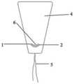
图6是本发明实施例4中弹性膜的主视图;Figure 6 is a front view of the elastic film in Example 4 of the present invention;
图7是本发明实施例4中弹性膜的后视图;7 is a rear view of the elastic film in Example 4 of the present invention;
图8是本发明实施例5中弹性膜的主视图;FIG. 8 is a front view of the elastic film in
图9是本发明实施例5中弹性膜的后视图;Figure 9 is a rear view of the elastic film in Example 5 of the present invention;
图10是本发明实施例6中弹性膜的主视图;10 is a front view of the elastic film in Example 6 of the present invention;
图11是本发明实施例6中弹性膜的后视图;Figure 11 is a rear view of the elastic film in Example 6 of the present invention;
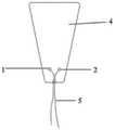
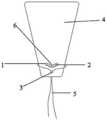
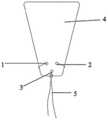
其中,1为第一连线通孔,2为第二连线通孔,3为第三连线通孔,4为硅橡胶膜片,5为绳线,6为细管。Wherein, 1 is a first connection through hole, 2 is a second connection through hole, 3 is a third connection through hole, 4 is a silicone rubber diaphragm, 5 is a rope, and 6 is a thin tube.
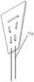
图12是本发明实施例7中弹性膜的示意图;12 is a schematic diagram of an elastic film in Example 7 of the present invention;
图13为图12中E区的放大图;Fig. 13 is the enlarged view of E area in Fig. 12;
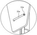
其中,1e为硅橡胶膜片,2e为输送装置,11e为取出丝线,13e为植入丝线,15e为细管。Among them, 1e is a silicone rubber diaphragm, 2e is a delivery device, 11e is a removal wire, 13e is an implantation wire, and 15e is a thin tube.
图14是本发明实施例7中加厚部的示意图;14 is a schematic diagram of a thickened portion in Embodiment 7 of the present invention;
其中,16f为铆钉结构的加厚部。Among them, 16f is the thickened part of the rivet structure.
图15是本发明对比例1中弹性膜的主视图;15 is a front view of the elastic film in Comparative Example 1 of the present invention;
图16是本发明对比例1中弹性膜的后视图;16 is a rear view of the elastic film in Comparative Example 1 of the present invention;
图17是本发明对比例2中弹性膜的主视图;17 is a front view of the elastic film in Comparative Example 2 of the present invention;
图18是本发明对比例2中弹性膜的后视图;Figure 18 is a rear view of the elastic film in Comparative Example 2 of the present invention;
图19是本发明对比例3中弹性膜的主视图;Figure 19 is a front view of the elastic film in Comparative Example 3 of the present invention;
图20是本发明对比例3中弹性膜的后视图;Figure 20 is a rear view of the elastic film in Comparative Example 3 of the present invention;
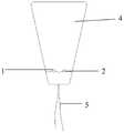
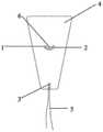
其中,1为第一连线通孔,2为第二连线通孔,3为第三连线通孔,4为硅橡胶膜片,5为绳线,6为细管。Wherein, 1 is a first connection through hole, 2 is a second connection through hole, 3 is a third connection through hole, 4 is a silicone rubber diaphragm, 5 is a rope, and 6 is a thin tube.
具体实施方式Detailed ways
下面通过具体实施方式来进一步说明本发明的技术方案。本领域技术人员应该明了,所述实施例仅仅是帮助理解本发明,不应视为对本发明的具体限制。The technical solutions of the present invention are further described below through specific embodiments. It should be understood by those skilled in the art that the embodiments are only for helping the understanding of the present invention, and should not be regarded as a specific limitation of the present invention.
实施例1Example 1
本实施例提供一种弹性膜,所述弹性膜包括:设置有连线通孔(尾丝孔)的硅橡胶膜片以及穿插在硅橡胶膜片连线通孔中的绳线(取出丝线);所述绳线上套设有细管。This embodiment provides an elastic film, the elastic film includes: a silicone rubber diaphragm provided with a wire through hole (tail wire hole) and a wire (taken out wire) inserted in the wire through hole of the silicone rubber diaphragm ; A thin tube is sleeved on the rope.
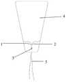
由图1和图2可知,连线通孔的个数为3个,其中3个连线通孔为呈倒等边三角形分布的第一连线通孔1、第二连线通孔2和第三连线通孔3,第一连线通孔1和第二连线通孔2位于第三连线通孔3的上方;硅橡胶膜片4的形状为倒梯形,倒梯形的高为25mm,上底长度为20mm,下底长度为15mm;第一连线通孔1和第二连线通孔2到硅橡胶膜片4下底边的垂直距离为5mm,第三连线通孔3到硅橡胶膜片4下底边的垂直距离为2mm;连线通孔的形状为圆形,连线通孔的直径为1.2mm,连线通孔的直径大于绳线5的直径,绳线5的直径为1mm,绳线5为单丝单股缝纫线;套设在第一连线通孔1和第二连线通孔2之间绳线上的细管6为硅胶管,硅胶管的直径大于连线通孔的直径;绳线5的两自由端分别穿过硅橡胶膜片4正面的第一连线通孔1和第二连线通孔2,合并从硅橡胶膜片4反面穿过第三通孔3后固定。It can be seen from FIG. 1 and FIG. 2 that the number of connecting through holes is 3, and the three connecting through holes are the first connecting through
本实施例得到的弹性膜抽紧固定端绳线,第三连线通孔受力,通过持续收紧绳线,致使第一连线通孔和第二连线通孔间的绳线受力,从而能获得较小的横截面积;套设在第一连线通孔和第二连线通孔间绳线上的弹性硅胶管增大与硅橡胶膜片的接触面积,减小了绳线对硅橡胶膜片的切割力,增大了绳线和硅橡胶膜片的连接力,通过对连接力进行连续4次的测定(即对一端固定硅橡胶膜片、一端固定绳线后用拉伸机进行拉力测试硅橡胶膜片断裂所需的力值)测试值分别为4.2N、5.2N、4.8N、4.1N,其平均值为4.6N,说明该弹性膜一方面能够增加绳线和硅橡胶膜片的连接力,另一方面能够减小硅橡胶膜片的截面积,便于放置到子宫内部。The elastic film obtained in this example tightens the rope at the fixed end, and the third connection through hole is stressed. By continuously tightening the rope, the rope between the first connection through hole and the second connection through hole is stressed. , so that a smaller cross-sectional area can be obtained; the elastic silicone tube sleeved on the rope between the first connection through hole and the second connection through hole increases the contact area with the silicone rubber diaphragm, reducing the rope The cutting force of the wire to the silicone rubber diaphragm increases the connection force between the rope and the silicone rubber diaphragm. The tensile force required for the tensile test of the tensile machine to break the silicone rubber diaphragm) The test values are 4.2N, 5.2N, 4.8N, and 4.1N respectively, and the average value is 4.6N, indicating that the elastic film can increase the number of ropes on the one hand. The connection force with the silicone rubber diaphragm, on the other hand, can reduce the cross-sectional area of the silicone rubber diaphragm, which is convenient to be placed inside the uterus.
实施例2Example 2
本实施例提供一种弹性膜,所述弹性膜包括:设置有连线通孔的硅橡胶膜片以及穿插在硅橡胶膜片连线通孔中的绳线;所述连线通孔间的取出丝线上套设有细管。This embodiment provides an elastic film, the elastic film includes: a silicone rubber diaphragm provided with through-holes for connecting wires and a cord inserted in the through-holes of the silicone rubber diaphragm; A thin tube is sheathed on the thread taken out.
如图3所示,连线通孔的个数为12个,取出丝线11g的两自由端分别穿过硅橡胶膜片上的12个连线通孔,其中任两个连线通孔间的取出丝线11g上套设有细管。As shown in Figure 3, the number of connecting through holes is 12, and the two free ends of the wire 11g are taken out through the 12 connecting through holes on the silicone rubber diaphragm respectively. Take out the silk thread 11g and set a thin tube on it.
将本实施例得到的弹性膜抽紧固定端取出丝线,并持续收紧取出丝线,致使连线通孔间的取出丝线的受力较大,套设在任两个连线通孔间取出丝线上的弹性硅胶管增大与硅橡胶膜片的接触面积,可减小绳线对硅橡胶膜片的切割力;通过对连接力进行连续4次的测定,测试值分别为6.0N、5.8N、6.2N、5.5N,其平均值为5.9N,本实施例中多个连线通孔更利于力的分散,会造成连接力较大,但是多个通孔可能会影响硅橡胶膜片整体的切应力,且硅橡胶膜片截面积的降低程度会较低,通过性会较差。The elastic film obtained in this example is tightened and the fixed end is taken out of the silk thread, and the silk thread is continuously tightened to take out the silk thread, so that the force of the taken out silk thread between the connecting through holes is relatively large, and it is sleeved on the taking out silk thread between any two connecting through holes. The elastic silicone tube increases the contact area with the silicone rubber diaphragm, which can reduce the cutting force of the rope on the silicone rubber diaphragm; by measuring the connection force for 4 consecutive times, the test values are 6.0N, 5.8N, 6.2N, 5.5N, the average value is 5.9N. In this embodiment, multiple connecting through holes are more conducive to the dispersion of force, which will cause a larger connecting force, but multiple through holes may affect the overall performance of the silicone rubber diaphragm. Shear stress, and the reduction of the cross-sectional area of the silicone rubber diaphragm will be lower, and the passability will be poor.
实施例3Example 3
本实施例提供一种弹性膜,所述弹性膜包括:设置有连线通孔的硅橡胶膜片以及穿插在硅橡胶膜片连线通孔中的绳线;所述绳线上套设有细管。This embodiment provides an elastic membrane, the elastic membrane includes: a silicone rubber membrane provided with a connecting wire through hole and a cord inserted in the connecting through hole of the silicone rubber membrane; the cord is sleeved with a thin tube.
由图4和图5可知,连线通孔的个数为2个,其中2个连线通孔为第一连线通孔1和第二连线通孔2,第一连线通孔1和第二连线通孔2的连线与硅橡胶膜片4的底边平行;硅橡胶膜片4的形状为倒梯形,倒梯形的高为25mm,上底长度为20mm,下底长度为15mm;第一连线通孔1到硅橡胶膜片4下底边的垂直距离为6mm;连线通孔的形状为圆形,连线通孔的直径为1mm,连线通孔的直径大于绳线5的直径,绳线5的直径为0.8mm,绳线5为单丝单股缝纫线;套设在第一连线通孔1和第二连线通孔2之间绳线5上的细管6为硅胶管,硅胶管的直径大于连线通孔的直径;绳线5的两自由端分别穿过硅橡胶膜片4正面的第一连线通孔1和第二连线通孔2,合并固定。It can be seen from FIG. 4 and FIG. 5 that the number of connecting through holes is 2, and the two connecting through holes are the first connecting through hole 1 and the second connecting through hole 2, and the first connecting through hole 1 The connection line with the second connection through hole 2 is parallel to the bottom edge of the silicone rubber diaphragm 4; the shape of the silicone rubber diaphragm 4 is an inverted trapezoid, the height of the inverted trapezoid is 25mm, the length of the upper bottom is 20mm, and the length of the lower bottom is 15mm; the vertical distance from the first connection hole 1 to the bottom edge of the silicone rubber diaphragm 4 is 6mm; the shape of the connection hole is circular, the diameter of the connection hole is 1mm, and the diameter of the connection hole is larger than The diameter of the rope 5, the diameter of the rope 5 is 0.8mm, and the rope 5 is a monofilament single-strand sewing thread; The thin tube 6 is a silicone tube, and the diameter of the silicone tube is larger than the diameter of the connecting wire through hole; the two free ends of the rope 5 pass through the first connecting wire through hole 1 and the second connecting wire through the front side of the silicone rubber diaphragm 4 respectively.
将本实施例得到的绕线的弹性膜抽紧固定端绳线,并持续收紧绳线,致使第一连线通孔和第二连线通孔间的绳线受力较大,在力的作用下可以减小硅橡胶膜片的截面积,套设在第一连线通孔和第二连线通孔间绳线上的弹性硅胶管增大与硅橡胶膜片的接触面积,可减小绳线对硅橡胶膜片的切割力;通过对连接力进行连续4次的测定,测试值分别为4.1N、4.4N、3.7N、4.1N,其平均值为4.1N,可知,两个连线通孔可以增加力的分散,会造成连接力相对较大,且通过力的作用能够减小硅橡胶膜片的截面积,通过性会较好。The elastic film of the winding obtained in this embodiment is tightened to the fixed end rope, and the rope is continuously tightened, so that the rope between the first connection through hole and the second connection through hole is subjected to a large force, and the force The cross-sectional area of the silicone rubber diaphragm can be reduced under the action of the silicone rubber diaphragm, and the elastic silicone tube sleeved on the wire between the first connection through hole and the second connection through hole increases the contact area with the silicone rubber diaphragm, which can increase the contact area of the silicone rubber diaphragm. Reduce the cutting force of the rope on the silicone rubber diaphragm; by measuring the connection force four times in a row, the test values are 4.1N, 4.4N, 3.7N, and 4.1N, and the average value is 4.1N. It can be seen that the two The connection through holes can increase the dispersion of the force, which will cause the connection force to be relatively large, and the cross-sectional area of the silicone rubber diaphragm can be reduced by the action of the force, and the passability will be better.
实施例4Example 4
本实施例提供一种弹性膜,所述弹性膜包括:设置有连线通孔的硅橡胶膜片以及穿插在硅橡胶膜片连线通孔中的绳线;所述绳线上套设有细管。This embodiment provides an elastic membrane, the elastic membrane includes: a silicone rubber membrane provided with a connecting wire through hole and a cord inserted in the connecting through hole of the silicone rubber membrane; the cord is sleeved with a thin tube.
由图6和图7可知,连线通孔的个数为3个,其中3个连线通孔为呈倒等边三角形分布的第一连线通孔1、第二连线通孔2和第三连线通孔3,第一连线通孔1和第二连线通孔2位于第三连线通孔3的上方;硅橡胶膜片4的形状为倒梯形,倒梯形的高为30mm,上底长度为30mm,下底长度为10mm;第一连线通孔1和第二连线通孔2到硅橡胶膜片4下底边的垂直距离为5mm,第三连线通孔3到硅橡胶膜片4下底边的垂直距离为2mm;连线通孔的形状为圆形,连线通孔的直径为0.6mm,连线通孔的直径大于绳线5的直径,绳线5的直径为0.5mm,绳线5为单丝单股缝纫线;套设在第一连线通孔1和第二连线通孔2之间绳线5上的细管6为硅胶管,硅胶管的直径大于连线通孔的直径;绳线5的一自由端穿过硅橡胶膜片4正面的第一连线通孔1,另一自由端依次穿过细管6和硅橡胶膜片4正面的第二连线通孔2,而后分别绕至硅橡胶膜片4的正面,合并穿过第三连线通孔3后固定。It can be seen from FIG. 6 and FIG. 7 that the number of connecting through holes is 3, and the three connecting through holes are the first connecting through
将本实施例得到的弹性膜抽紧固定端绳线,第三连线通孔受力,迫使绳线压缩硅橡胶膜片两侧的外轮廓线,从而获得较小的横截面积;持续收紧绳线,致使第一连线通孔和第二连线通孔间的绳线受力,套设在第一连线通孔和第二连线通孔间绳线上的弹性硅胶管增大与硅橡胶膜片的接触面积,减小了绳线对硅橡胶膜片的切割力,通过对连接力进行连续4次的测定,测试值分别为6.2N、5.9N、6.9N、6.0N,其平均值为6.3N,说明本发明中绳线和硅橡胶膜片间的连接力较大,可减少绳线对硅橡胶膜片的切割损伤,且通过抽紧固定端,绳线会对硅橡胶膜片的外轮廓线产生压力,可进一步减小硅橡胶膜片的截面积,便于放置到子宫内部。The elastic film obtained in this example is tightened to the fixed end rope, and the third connecting wire through hole is stressed, forcing the rope to compress the outer contour lines on both sides of the silicone rubber diaphragm, thereby obtaining a smaller cross-sectional area; Tighten the cord, so that the cord between the first connection hole and the second connection hole is stressed, and the elastic silicone tube sleeved on the cord between the first connection hole and the second connection hole increases the force. The large contact area with the silicone rubber diaphragm reduces the cutting force of the rope on the silicone rubber diaphragm. By measuring the connection force for 4 consecutive times, the test values are 6.2N, 5.9N, 6.9N, and 6.0N. , the average value is 6.3N, which shows that the connection force between the rope and the silicone rubber diaphragm in the present invention is relatively large, which can reduce the cutting damage of the rope to the silicone rubber diaphragm, and by tightening the fixed end, the rope will cause damage to the silicone rubber diaphragm. The outer contour of the silicone rubber diaphragm generates pressure, which can further reduce the cross-sectional area of the silicone rubber diaphragm, which is convenient for placement inside the uterus.
实施例5Example 5
本实施例提供一种弹性膜,所述弹性膜包括:设置有连线通孔的硅橡胶膜片以及穿插在硅橡胶膜片连线通孔中的绳线;所述绳线上套设有细管。This embodiment provides an elastic membrane, the elastic membrane includes: a silicone rubber membrane provided with a connecting wire through hole and a cord inserted in the connecting through hole of the silicone rubber membrane; the cord is sleeved with a thin tube.
如图8和9所示,与实施例4的区别仅在于绳线在连线通孔中的穿插方式不同,其绳线在连线通孔中的穿插方式为:绳线5的两自由端分别穿过硅橡胶膜片4正面的第一连线通孔1和第连线二通孔2,而后绳线5的两自由端分别绕至硅橡胶膜片4正面,合并依次穿过第一连线通孔1与第二连线通孔2之间的绳线5和硅橡胶膜片4围设形成的缝隙和第三连线通孔3后固定。As shown in Figures 8 and 9, the only difference from
本实施例得到的弹性膜抽紧固定端丝线,第三连线通孔受力,迫使绳线压缩硅橡胶膜片两侧的外轮廓线,从而获得较小的横截面积;持续收紧绳线,致使第一连线通孔和第二连线通孔间的绳线受力,绳线合并后会穿过第一连线通孔与第二连线通孔之间的绳线和硅橡胶膜片围设形成的缝隙,会使绳线对硅橡胶膜片的切割力分散,套设在第一连线通孔和第二连线通孔间绳线上的弹性硅胶管增大与硅橡胶膜片的接触面积,减小了绳线对硅橡胶膜片的切割力,增大了绳线和硅橡胶膜片的连接力,通过对连接力进行连续4次的测定,测试值分别为6.2N、5.2N、5.7N、5.1N,其平均值为5.6N,本实施例中绳线和硅橡胶膜片的连接力较大,便于力的分散,可减小绳线对硅橡胶膜片的切割损伤,且通过抽紧固定端,绳线会对硅橡胶膜片的外轮廓线产生压力,可进一步减小硅橡胶膜片的截面积,便于放置到子宫内部。The elastic film obtained in this example tightens the wire at the fixed end, and the third connecting wire through hole is stressed, forcing the wire to compress the outer contour lines on both sides of the silicone rubber diaphragm, so as to obtain a smaller cross-sectional area; continue to tighten the wire the wire between the first wire through hole and the second wire through hole is stressed, and the wire will pass through the wire and silicon between the first wire through hole and the second wire through hole after being merged. The gap formed by the rubber diaphragm will disperse the cutting force of the rope on the silicone rubber diaphragm, and the elastic silicone tube sleeved on the rope between the first connection through hole and the second connection through hole increases and The contact area of the silicone rubber diaphragm reduces the cutting force of the rope on the silicone rubber diaphragm, and increases the connection force between the rope and the silicone rubber diaphragm. are 6.2N, 5.2N, 5.7N, and 5.1N, and the average value is 5.6N. In this embodiment, the connection force between the rope and the silicone rubber diaphragm is relatively large, which facilitates the dispersion of the force and reduces the effect of the rope on the silicone rubber. The cutting damage of the diaphragm, and by tightening the fixed end, the rope will exert pressure on the outer contour of the silicone rubber diaphragm, which can further reduce the cross-sectional area of the silicone rubber diaphragm and facilitate placement inside the uterus.
实施例6Example 6
与实施例3的区别在于绳线穿插在连接通孔中的方式不同,如图10和图11所示,绳线的两自由端分别穿过硅橡胶膜片4正面的第一连线通孔1和第二连线通孔2,而后绕过硅橡胶膜片4的外轮廓线至硅橡胶膜片4的正面,而后再穿过第二连线通孔2和第一连线通孔1,合并后固定。The difference from Example 3 lies in the way in which the cord is inserted into the connecting through hole. As shown in Figures 10 and 11 , the two free ends of the cord pass through the first connecting through hole on the front side of the
本实施例得到的绕线的硅橡胶膜片抽紧固定端绳线,并持续收紧绳线,致使第一连线通孔和第二连线通孔间的绳线受力较大,在力的作用下可以压缩硅橡胶膜片两侧的外轮廓线,能够减小硅橡胶膜片的截面积,套设在第一连线通孔和第二连线通孔间绳线上的弹性硅胶管增大与硅橡胶膜片的接触面积,可减小绳线对硅橡胶膜片的切割力;通过对连接力进行连续4次的测定,测试值分别为3.2N、3.8N、3.1N、3.7N,其平均值为3.5N,说明本发明中绳线和硅橡胶膜片间的连接力较大,可减少绳线对硅橡胶膜片的切割损伤,且通过抽紧固定端,绳线会对硅橡胶膜片的外轮廓线产生压力,可进一步减小硅橡胶膜片的截面积,便于放置到子宫内部。The wound silicone rubber diaphragm obtained in this example tightens the rope at the fixed end, and continues to tighten the rope, so that the rope between the first connection through hole and the second connection through hole is subjected to a large force, and in the Under the action of force, the outer contour lines on both sides of the silicone rubber diaphragm can be compressed, which can reduce the cross-sectional area of the silicone rubber diaphragm, and the elasticity of the wire set between the first connection through hole and the second connection through hole The increase of the contact area between the silicone tube and the silicone rubber diaphragm can reduce the cutting force of the rope on the silicone rubber diaphragm; by measuring the connection force for 4 consecutive times, the test values are 3.2N, 3.8N, and 3.1N respectively. , 3.7N, the average value is 3.5N, indicating that the connection force between the rope and the silicone rubber diaphragm in the present invention is large, which can reduce the cutting damage of the rope to the silicone rubber diaphragm, and by tightening the fixed end, the rope The thread will exert pressure on the outer contour of the silicone rubber diaphragm, which can further reduce the cross-sectional area of the silicone rubber diaphragm and facilitate placement inside the uterus.
实施例7Example 7
本实施例提供一种弹性膜,所述弹性膜包括:设置有连线通孔的硅橡胶膜片以及穿插在硅橡胶膜片连线通孔中的绳线;所述绳线上套设有细管。This embodiment provides an elastic membrane, the elastic membrane includes: a silicone rubber membrane provided with a connecting wire through hole and a cord inserted in the connecting through hole of the silicone rubber membrane; the cord is sleeved with a thin tube.
由图12和图13可知,尾丝孔的个数为2个,两个尾丝孔的连线和硅橡胶膜片的底边平行;硅橡胶膜片1e的形状为倒梯形,倒梯形的高为30mm,上底长度为30mm,下底长度为10mm;两个尾丝孔到硅橡胶膜片1e下底边的垂直距离为5mm;尾丝孔边缘设置有铆钉结构16f(如图14所示)进行加厚,铆钉结构16f的厚度为1mm,尾丝孔的形状为圆形,尾丝孔的直径为0.6mm,尾丝孔的直径大于取出丝线11e的直径,取出丝线11e的直径为0.5mm,取出丝线11e为单丝单股缝纫线;套设在两个尾丝孔间取出丝线11e上的细管15e为硅胶管,细管15e的直径大于取出丝线的直径,其中其内径为0.5mm,外径为0.8mm,细管15e的长度应大于两个尾丝孔的圆心之间的直线长度,并短于两个尾丝孔最长距离;取出丝线11e的两自由端分别穿过硅橡胶膜片1e正面的两个尾丝孔,而后分别绕至硅橡胶膜片1e的正面,合并后固定;该弹性膜还包括2个植入丝孔(即固定通孔),植入丝孔通过植入丝线13e将弹性膜和输送装置2e(即放置装置)固定在一起,植入丝孔边缘设置有铆钉结构16f(见图14)进行加厚,铆钉结构16f的厚度为1mm,植入丝孔的形状为圆形,植入丝孔的直径为0.6mm;植入丝线13e的两自由端分别穿过硅橡胶膜片1e正面的两个植入丝线孔,合并穿过输送装置2e。It can be seen from Figure 12 and Figure 13 that the number of tail wire holes is 2, and the connecting line of the two tail wire holes is parallel to the bottom edge of the silicone rubber diaphragm; the shape of the
本实施例中取出丝线11e和植入丝线13e的背对输送系统2e的线圈上套上细管15e,加强取出丝线11e和植入丝线13e在割裂时受力,将取出丝线11e和植入丝线13e割裂压强转嫁到细管15e上;将线圈的背对输送系统2e的部分套上细管即可,而面对输送系统2e的丝线不套细管,以方便输送时撑直;如图14所示,铆钉结构16f为预制好的两头大的管状物;通过将铆钉结构16f卡在尾丝孔和植入丝孔内再穿取出丝线和植入丝线,可以达到加强孔使其耐割裂的目的。In this embodiment, the coils of the
将本实施例得到的弹性膜抽紧固定端取出丝线,并持续收紧取出丝线,致使两个尾丝孔间的绳线受力较大,套设在两个尾丝孔间取出丝线上的弹性硅胶管增大与硅橡胶膜片的接触面积,可减小绳线对硅橡胶膜片的切割力,铆钉结构的加厚部可以减少取出丝线对硅橡胶膜片的切割;通过对连接力进行连续4次的测定,测试值分别为4.5N、4.9N、4.1N、4.4N,其平均值为4.8N,可知,两个连线通孔可以增加力的分散,会造成连接力较大,在进行抽动绳线时可以降低硅橡胶膜片的截面积,且在尾丝孔边缘设置有加厚部,能够进一步降低绳线对硅橡胶膜片的损伤。The elastic film obtained in this example is tightened to take out the silk thread from the fixed end, and the silk thread is continuously tightened to take out the silk thread, so that the rope between the two tail thread holes is subjected to a large force, and the thread is sleeved between the two tail thread holes to take out the silk thread. The elastic silicone tube increases the contact area with the silicone rubber diaphragm, which can reduce the cutting force of the rope on the silicone rubber diaphragm, and the thickened part of the rivet structure can reduce the cutting of the silicone rubber diaphragm by the thread; Four consecutive measurements were carried out, and the test values were 4.5N, 4.9N, 4.1N, and 4.4N, and the average value was 4.8N. It can be seen that the two connecting through holes can increase the dispersion of the force, which will cause a large connecting force. , the cross-sectional area of the silicone rubber diaphragm can be reduced when the rope is pulled, and a thickened part is arranged on the edge of the tail wire hole, which can further reduce the damage of the rope to the silicone rubber diaphragm.
对比例1Comparative Example 1
由图15和图16可知,本实施例和实施例1的区别仅在于第一连线通孔1和第二连线通孔2到硅橡胶膜片4下底边的垂直距离为12.5mm。15 and 16 , the difference between this embodiment and
本实施例得到的弹性膜抽紧固定端绳线,由于第一连线通孔和第二连线通孔到硅橡胶膜片下底边的垂直距离过长,在拉紧绳线时,因为孔位置的原因,硅橡胶膜片可能会出现对折,压握后的弹性膜片横截面较大,通过性较差;通过持续收紧绳线,致使第一连线通孔和第二连线通孔间的绳线受力,套设在第一连线通孔和第二连线通孔间绳线上的弹性硅胶管增大与硅橡胶膜片的接触面积,减小了绳线对硅橡胶膜片的切割力,增大了绳线和硅橡胶膜片的连接力,通过对连接力进行连续4次的测定,测试值分别为4.3N、4.7N、5.1N、4.3N,其平均值为4.6N,通过实施例1和对比例1的对比,说明通过调整第一连线通孔1和第二连线通孔2到硅橡胶膜片4下底边的垂直距离不会对绳线和硅橡胶膜片的连接力产生太大影响,但是第一连线通孔和第二连线通孔相对于硅橡胶膜片宽度的距离较低,在抽动绳线时,硅橡胶膜片可能会出现对折,造成压握后的弹性膜片的横截面积较大,通过性较差。The elastic film obtained in this example tightens the fixed end rope, because the vertical distance from the first connection through hole and the second connection through hole to the bottom edge of the silicone rubber diaphragm is too long, when the rope is tightened, because Due to the position of the hole, the silicone rubber diaphragm may be folded in half, and the cross section of the elastic diaphragm after pressing is large, and the passability is poor; by continuously tightening the rope, the first connection through hole and the second connection The rope between the through holes is stressed, and the elastic silicone tube sleeved on the rope between the first connection through hole and the second connection through hole increases the contact area with the silicone rubber diaphragm and reduces the pair of ropes. The cutting force of the silicone rubber diaphragm increases the connection force between the rope and the silicone rubber diaphragm. By measuring the connection force four times in a row, the test values are 4.3N, 4.7N, 5.1N, and 4.3N, respectively. The average value is 4.6N. Through the comparison between Example 1 and Comparative Example 1, it is shown that by adjusting the vertical distance between the first connecting
对比例2Comparative Example 2
由图17和图18可知,本对比例与实施例3的区别仅在于第一连线通孔和第二连线通孔至硅橡胶膜片4下底边的垂直距离为12.5mm。17 and 18 , the difference between this comparative example and Example 3 is only that the vertical distance from the first and second wiring through holes to the bottom edge of the
将本实施例得到的绕线的弹性膜抽紧固定端绳线,并持续收紧绳线,致使第一连线通孔和第二连线通孔间的绳线受力较大,因为孔位置的原因,硅橡胶膜片可能会出现对折,压握后的弹性膜片横截面较大,通过性较差,套设在第一连线通孔和第二连线通孔间绳线上的弹性硅胶管增大与硅橡胶膜片的接触面积,可减小绳线对硅橡胶膜片的切割力;通过对连接力进行连续4次的测定,测试值分别为3.9N、4.5N、4.1N、4.8N,其平均值为4.3N,通过本对比例和实施例3的对比可知,两个连线通孔相对应三个连线通孔不利于力的分散,会造成连接力较小,且绳线的自由端不经过硅橡胶膜片的外轮廓线,也不会对硅橡胶膜片的外轮廓线产生压力,此外,第一连线通孔和第二连线通孔间的距离相对应同一水平线的硅橡胶膜片的宽度较低,在拉动绳线时,也不利于对硅橡胶膜片施力,因此不利于截面积的降低。The elastic film of the winding obtained in this example is tightened to the fixed end rope, and the rope is continuously tightened, so that the rope between the first connection through hole and the second connection through hole is subjected to greater force, because the hole Due to the location, the silicone rubber diaphragm may be folded in half. The elastic diaphragm after pressing is large in cross section and has poor passability. It is sleeved on the rope between the first connection through hole and the second connection through hole. The elastic silicone tube increases the contact area with the silicone rubber diaphragm, which can reduce the cutting force of the rope on the silicone rubber diaphragm; by measuring the connection force for 4 consecutive times, the test values are 3.9N, 4.5N, 4.1N, 4.8N, and the average value is 4.3N. From the comparison between this comparative example and Example 3, it can be seen that the corresponding three connecting through holes of two connecting holes is not conducive to the dispersion of force, which will cause the connecting force to be relatively weak. It is small, and the free end of the rope does not pass through the outer contour of the silicone rubber diaphragm, nor does it exert pressure on the outer contour of the silicone rubber diaphragm. The distance corresponding to the width of the silicone rubber diaphragm on the same horizontal line is relatively low. When pulling the rope, it is not conducive to exerting force on the silicone rubber diaphragm, so it is not conducive to the reduction of the cross-sectional area.
对比例3Comparative Example 3
与实施例5的区别仅在于连线通孔间的绳线上不套设细管,其余组成均与实施例5相同。The only difference from
通过对对比例3中绳线和硅橡胶膜片的连接力进行连续4次测定,测定值分别为2.9N、3.8N、3.2N、3.3N,其平均值为3.3N,通过实施例5和对比例3的对比,说明在绳线上套设细管,可以有效减小绳线对硅橡胶膜片的切割,避免因绳线对硅橡胶膜片的切割力较大,使硅橡胶膜片无法顺利的从体内取出。By comparing the connection force of the rope and the silicone rubber diaphragm in Comparative Example 3 for 4 consecutive times, the measured values are 2.9N, 3.8N, 3.2N, and 3.3N, respectively, and the average value is 3.3N. The comparison of Comparative Example 3 shows that setting a thin tube on the rope can effectively reduce the cutting of the silicone rubber diaphragm by the rope, and avoid the silicone rubber diaphragm due to the large cutting force of the rope on the silicone rubber diaphragm. It cannot be removed from the body smoothly.
申请人声明,以上所述仅为本发明的具体实施方式,但本发明的保护范围并不局限于此,所属技术领域的技术人员应该明了,任何属于本技术领域的技术人员在本发明揭露的技术范围内,可轻易想到的变化或替换,均落在本发明的保护范围和公开范围之内。The applicant declares that the above are only specific embodiments of the present invention, but the protection scope of the present invention is not limited thereto. Those skilled in the art should Changes or substitutions that can be easily conceived within the technical scope all fall within the protection scope and disclosure scope of the present invention.
Claims (8)
Applications Claiming Priority (3)
| Application Number | Priority Date | Filing Date | Title |
|---|---|---|---|
| CN2018103542772 | 2018-04-19 | ||
| CN201810354277 | 2018-04-19 | ||
| CN201910252398.0ACN109758622B (en) | 2018-04-19 | 2019-03-29 | an elastic membrane |
Related Parent Applications (1)
| Application Number | Title | Priority Date | Filing Date |
|---|---|---|---|
| CN201910252398.0ADivisionCN109758622B (en) | 2018-04-19 | 2019-03-29 | an elastic membrane |
Publications (2)
| Publication Number | Publication Date |
|---|---|
| CN113318279A CN113318279A (en) | 2021-08-31 |
| CN113318279Btrue CN113318279B (en) | 2022-09-20 |
Family
ID=66460268
Family Applications (8)
| Application Number | Title | Priority Date | Filing Date |
|---|---|---|---|
| CN201910252398.0AActiveCN109758622B (en) | 2018-04-19 | 2019-03-29 | an elastic membrane |
| CN202110765651.XAActiveCN113262332B (en) | 2018-04-19 | 2019-03-29 | Elastic film |
| CN202011415977.1AActiveCN112535795B (en) | 2018-04-19 | 2019-03-29 | an elastic membrane |
| CN202110765285.8AActiveCN113318279B (en) | 2018-04-19 | 2019-03-29 | an elastic membrane |
| CN201910270137.1AActiveCN109925539B (en) | 2018-04-19 | 2019-04-04 | Elastic membrane, preparation method and application thereof |
| CN202011416292.9AActiveCN112494464B (en) | 2018-04-19 | 2019-04-04 | Elastic membrane and preparation method thereof |
| CN201910270119.3AActiveCN109925537B (en) | 2018-04-19 | 2019-04-04 | A kind of elastic film, its preparation method and application |
| CN201910270128.2AActiveCN109925538B (en) | 2018-04-19 | 2019-04-04 | Elastic membrane, preparation method and application thereof |
Family Applications Before (3)
| Application Number | Title | Priority Date | Filing Date |
|---|---|---|---|
| CN201910252398.0AActiveCN109758622B (en) | 2018-04-19 | 2019-03-29 | an elastic membrane |
| CN202110765651.XAActiveCN113262332B (en) | 2018-04-19 | 2019-03-29 | Elastic film |
| CN202011415977.1AActiveCN112535795B (en) | 2018-04-19 | 2019-03-29 | an elastic membrane |
Family Applications After (4)
| Application Number | Title | Priority Date | Filing Date |
|---|---|---|---|
| CN201910270137.1AActiveCN109925539B (en) | 2018-04-19 | 2019-04-04 | Elastic membrane, preparation method and application thereof |
| CN202011416292.9AActiveCN112494464B (en) | 2018-04-19 | 2019-04-04 | Elastic membrane and preparation method thereof |
| CN201910270119.3AActiveCN109925537B (en) | 2018-04-19 | 2019-04-04 | A kind of elastic film, its preparation method and application |
| CN201910270128.2AActiveCN109925538B (en) | 2018-04-19 | 2019-04-04 | Elastic membrane, preparation method and application thereof |
Country Status (7)
| Country | Link |
|---|---|
| US (1) | US12427106B2 (en) |
| EP (1) | EP3639864B1 (en) |
| JP (2) | JP7033342B2 (en) |
| KR (2) | KR20200144138A (en) |
| CN (8) | CN109758622B (en) |
| ES (1) | ES2930330T3 (en) |
| WO (1) | WO2019200694A1 (en) |
Families Citing this family (12)
| Publication number | Priority date | Publication date | Assignee | Title |
|---|---|---|---|---|
| JP2018166836A (en)* | 2017-03-30 | 2018-11-01 | 株式会社三洋物産 | Game machine |
| JP2018166837A (en)* | 2017-03-30 | 2018-11-01 | 株式会社三洋物産 | Game machine |
| KR20200144138A (en)* | 2018-04-19 | 2020-12-28 | 이푸룬 (상하이) 바이오테크놀러지 컴퍼니 리미티드 | Elastic film having a function of reactivating the function of the endometrial base layer in the uterine cavity, and a method for manufacturing the same |
| USD942007S1 (en)* | 2019-01-29 | 2022-01-25 | Yipurun (Shanghai) Biotechnology Co., Ltd. | Uterus stent |
| CN110279900A (en)* | 2019-08-01 | 2019-09-27 | 易浦润(上海)生物技术有限公司 | A kind of implantation piece and its preparation method and application |
| CN110721393A (en)* | 2019-10-28 | 2020-01-24 | 易浦润(上海)生物技术有限公司 | Uterine stent and preparation method thereof |
| CN110812645B (en)* | 2019-11-19 | 2023-02-28 | 浦易(上海)生物技术股份有限公司 | Tracheostomy tube and preparation method and application thereof |
| CN113941036B (en)* | 2019-12-31 | 2022-11-15 | 浦易(上海)生物技术股份有限公司 | Air flue support |
| CN111714260B (en)* | 2020-07-17 | 2024-05-17 | 上海浦瑞通医疗科技有限公司 | A bracket and its application |
| CN113274552A (en)* | 2021-05-21 | 2021-08-20 | 浙江德普斯医疗科技股份有限公司 | Slow-release antibacterial acellular matrix biological material and preparation method thereof |
| CN115624658B (en)* | 2022-10-20 | 2024-05-28 | 苏州纳晶医药技术有限公司 | Degradable uterine cavity drug delivery device and preparation method thereof |
| CN116688248B (en)* | 2023-06-20 | 2025-01-28 | 湖南大学 | Anti-tissue adhesion film and its preparation method and application |
Family Cites Families (62)
| Publication number | Priority date | Publication date | Assignee | Title |
|---|---|---|---|---|
| GB804262A (en)* | 1955-09-01 | 1958-11-12 | Normalair Ltd | Improvements in and relating to flexible diaphragms |
| GB1129712A (en)* | 1966-07-04 | 1968-10-09 | Basil Paul Appleby | Intra-uterine contraceptive device |
| CH477873A (en)* | 1967-07-14 | 1969-09-15 | Apamed Anst | Intrauterine contraceptive device |
| GB1334613A (en)* | 1970-11-30 | 1973-10-24 | Anderson I H W | Contraceptive devices |
| SE370622B (en)* | 1971-02-02 | 1974-10-28 | Tecna Corp | |
| US3734090A (en)* | 1971-04-15 | 1973-05-22 | F Shubeck | Intra-uterine contraceptive devices |
| BE791632A (en)* | 1971-11-20 | 1973-05-21 | Schering Ag | SILICONIC RUBBER-BASED SUPPORTS FOR MEDICINAL PRODUCTS |
| US3938515A (en)* | 1971-12-20 | 1976-02-17 | Alza Corporation | Novel drug permeable wall |
| US3913573A (en)* | 1972-10-02 | 1975-10-21 | Morton Gutnick | Intrauterine contraceptive devices with plural parallel leg segments |
| US3923051A (en)* | 1974-03-18 | 1975-12-02 | Samuel Soichet | Inflatable intrauterine contraceptive device for postpartum use |
| ES232273Y (en)* | 1977-11-23 | 1978-08-01 | INTRAUTERINE DEVICE WITH CONTRACEPTIVE AGENT FOR WOMEN. | |
| NZ200564A (en)* | 1982-05-10 | 1987-03-06 | Ahi Operations Ltd | Device for slowly releasing chemicals into body cavities of animals |
| US5153040A (en)* | 1985-03-11 | 1992-10-06 | Minnesota Mining And Manufacturing Co. | Wound dressing |
| CN2107263U (en)* | 1991-11-18 | 1992-06-17 | 刘铜华 | Medicated vaginal suppository |
| CN2170749Y (en)* | 1993-09-23 | 1994-07-06 | 刘锋 | Disposable intrauterine contraceptive device |
| US5755906A (en)* | 1996-08-12 | 1998-05-26 | Kimberly-Clark Worldwide, Inc. | Method of forming a tampon having a resilient member |
| US5873971A (en)* | 1996-11-14 | 1999-02-23 | Kimberly Clark Worldwide, Inc. | Method of forming a tampon which can be comfortably withdrawn from a body cavity |
| JP2002202232A (en)* | 2000-12-28 | 2002-07-19 | Electric Power Dev Co Ltd | Device and method for inspecting brittle tube |
| CN1210079C (en)* | 2001-04-25 | 2005-07-13 | 上海市计划生育科学研究所 | Medicine for vaginal ring and its application |
| CN1218686C (en)* | 2001-07-18 | 2005-09-14 | 上海市计划生育科学研究所 | Process for preparing medicine applying system in cavity or duct |
| CN1234350C (en)* | 2001-07-18 | 2006-01-04 | 上海市计划生育科学研究所 | Estrogen plaster used in cavity or duct |
| EP1400258A1 (en)* | 2002-09-18 | 2004-03-24 | Schering Oy | Pharmaceutical composition delivery device and its manufacturing process |
| CN2692992Y (en)* | 2004-04-19 | 2005-04-20 | 叶波 | Pregnancy promoting device for animals |
| US7862552B2 (en)* | 2005-05-09 | 2011-01-04 | Boston Scientific Scimed, Inc. | Medical devices for treating urological and uterine conditions |
| CN1899643B (en)* | 2005-07-20 | 2010-12-29 | 上海市计划生育科学研究所 | Pessary or intrauterine medicine release device containing antiestrogenic and anti-pregnant hormone composite preparation and its use |
| AU2007205862A1 (en)* | 2006-01-20 | 2007-07-26 | Fred Mermelstein | Method of treating atrophic vaginitis |
| BRPI0717739A2 (en)* | 2006-10-10 | 2014-07-29 | Celonova Biosciences Inc | MEDICAL DEVICE, METHOD FOR MANUFACTURING THIS AND METHOD FOR INCREASING THE BIOCOMPATIBILITY OF A MEDICAL DEVICE |
| CN101185779B (en)* | 2007-12-19 | 2010-06-02 | 上海赢生医疗科技有限公司 | A kind of preparation method of drug sustained-release stent |
| US20100279952A1 (en)* | 2007-12-21 | 2010-11-04 | Ninus Caram-Lelham | Cross-linked hydrogel containing an active substance |
| FI20085277A0 (en)* | 2008-04-02 | 2008-04-02 | Bayer Schering Pharma Oy | Intrauterine system |
| ES2628552T3 (en)* | 2009-01-18 | 2017-08-03 | Ocon Medical Ltd | Innovative intrauterine device |
| WO2011008896A2 (en)* | 2009-07-14 | 2011-01-20 | Board Of Regents, The University Of Texas System | Therapeutic methods using controlled delivery devices having zero order kinetics |
| CN101810526B (en)* | 2010-02-01 | 2011-07-27 | 袁智钢 | Biological support filled in uterine cavity |
| US20170319833A1 (en)* | 2010-03-28 | 2017-11-09 | Evestra, Inc. | Intravaginal drug delivery device |
| CN102861374B (en)* | 2011-07-08 | 2014-06-25 | 上海市计划生育科学研究所 | Pessulum capable of steadily releasing medicine |
| CN103007427B (en)* | 2011-09-21 | 2016-01-20 | 上海市计划生育科学研究所 | Slow controlled release in utero medicine-feeder and preparation method thereof |
| CN103285430A (en)* | 2012-02-29 | 2013-09-11 | 刘芳 | Preparation method of modified silicone rubber |
| CN103505802A (en)* | 2012-06-18 | 2014-01-15 | 国家人口计生委科学技术研究所 | Mifepristone shell-type vaginal ring preparation and application |
| MX2015001661A (en)* | 2012-08-09 | 2015-08-14 | Mithra Pharmaceuticals S A | Intrauterine device. |
| CN103784244B (en)* | 2012-10-30 | 2016-03-23 | 吴江永元生物科技有限公司 | A kind of intrauterine implant |
| CN202843882U (en)* | 2012-11-06 | 2013-04-03 | 李洪国 | Anti-adhesion intrauterine contraceptive device |
| PL2945580T3 (en)* | 2013-01-17 | 2020-11-02 | Pat&Co Bvba | RELEASING COPPER, HYBRID IUD WITH STOP ARM CONNECTED WITH A FRAMELESS BODY |
| CN203042397U (en)* | 2013-01-17 | 2013-07-10 | 朱晓明 | Degradable and absorbable uterine cavity anti-adhesion film |
| DE102013208924A1 (en)* | 2013-05-14 | 2014-12-04 | Johnson & Johnson Medical Gmbh | Surgical implant comprising a layer with openings |
| CN103301558B (en)* | 2013-06-25 | 2014-11-12 | 杭州安体科技有限公司 | Inductive uterine slow release system |
| CN103385781B (en)* | 2013-07-25 | 2015-07-22 | 董翠艳 | Contraceptive |
| CN103566462A (en)* | 2013-11-20 | 2014-02-12 | 上海达华药业有限公司 | Composite vagina dosing device, manufacturing method and application thereof |
| CN104771210A (en)* | 2014-01-10 | 2015-07-15 | 凌安东 | Foldable automatic replica isolating membrane for preventing metrosynizesis |
| CN103830034A (en)* | 2014-02-20 | 2014-06-04 | 烟台计生药械有限公司 | Intrauterine device adaptive to various uterine cavities |
| CN105078642B (en)* | 2014-05-14 | 2018-07-24 | 吴江永元生物科技有限公司 | A kind of uterus implant |
| CN105288831B (en)* | 2014-06-03 | 2019-11-08 | 辽宁省计划生育科学研究院 | A kind of biodegradation type drug delivery system of hollow tubular and preparation method thereof |
| CN204158524U (en)* | 2014-10-15 | 2015-02-18 | 江苏省苏北人民医院 | A kind of artificial iris |
| CN205251812U (en)* | 2015-09-29 | 2016-05-25 | 燕芳莉 | Fang gong chamber adhesion birth control ware |
| CN105902306B (en)* | 2016-03-18 | 2019-09-13 | 浙江中医药大学附属第一医院 | Endometrial repair device |
| CN205515128U (en)* | 2016-03-24 | 2016-08-31 | 中国医科大学附属盛京医院 | An inverted triangular intrauterine device capable of preventing and treating uterine fibroids |
| MX2018014362A (en)* | 2016-05-25 | 2019-07-10 | Kuster Martin | Enhanced intrauterine device. |
| CN106344230A (en)* | 2016-08-18 | 2017-01-25 | 马安军 | Anti-intrauterine adhesion device |
| GB2555373A (en)* | 2016-08-23 | 2018-05-02 | Reproductive Medicine And Gynaecology Associates Ltd | Implant |
| EP3446664A1 (en)* | 2017-08-21 | 2019-02-27 | Karl-Heinz Kurz | Intrauterine device |
| CN107744417B (en)* | 2017-10-18 | 2018-12-14 | 易浦润(上海)生物技术有限公司 | One kind can post-operation adhesion preventing instrument in degradable uterine cavity |
| CN107951550A (en)* | 2017-12-14 | 2018-04-24 | 易浦润(上海)生物技术有限公司 | A kind of degradable inner membrane of uterine cavity implant system |
| KR20200144138A (en)* | 2018-04-19 | 2020-12-28 | 이푸룬 (상하이) 바이오테크놀러지 컴퍼니 리미티드 | Elastic film having a function of reactivating the function of the endometrial base layer in the uterine cavity, and a method for manufacturing the same |
- 2018
- 2018-06-21KRKR1020207033257Apatent/KR20200144138A/ennot_activeCeased
- 2018-06-21EPEP18915384.4Apatent/EP3639864B1/enactiveActive
- 2018-06-21KRKR1020247013495Apatent/KR20240063996A/ennot_activeCeased
- 2018-06-21JPJP2020501342Apatent/JP7033342B2/enactiveActive
- 2018-06-21ESES18915384Tpatent/ES2930330T3/enactiveActive
- 2018-06-21WOPCT/CN2018/092136patent/WO2019200694A1/ennot_activeCeased
- 2019
- 2019-03-29CNCN201910252398.0Apatent/CN109758622B/enactiveActive
- 2019-03-29CNCN202110765651.XApatent/CN113262332B/enactiveActive
- 2019-03-29CNCN202011415977.1Apatent/CN112535795B/enactiveActive
- 2019-03-29CNCN202110765285.8Apatent/CN113318279B/enactiveActive
- 2019-04-04CNCN201910270137.1Apatent/CN109925539B/enactiveActive
- 2019-04-04CNCN202011416292.9Apatent/CN112494464B/enactiveActive
- 2019-04-04CNCN201910270119.3Apatent/CN109925537B/enactiveActive
- 2019-04-04CNCN201910270128.2Apatent/CN109925538B/enactiveActive
- 2019-06-19USUS16/445,939patent/US12427106B2/enactiveActive
- 2021
- 2021-10-11JPJP2021166957Apatent/JP7245552B2/enactiveActive
Also Published As
| Publication number | Publication date |
|---|---|
| CN109925537A (en) | 2019-06-25 |
| CN109758622B (en) | 2021-08-06 |
| US12427106B2 (en) | 2025-09-30 |
| CN109925537B (en) | 2022-03-01 |
| US20190328659A1 (en) | 2019-10-31 |
| KR20240063996A (en) | 2024-05-10 |
| JP7033342B2 (en) | 2022-03-10 |
| CN109925539B (en) | 2021-12-07 |
| CN109925538A (en) | 2019-06-25 |
| CN113318279A (en) | 2021-08-31 |
| CN112494464A (en) | 2021-03-16 |
| CN112535795B (en) | 2022-03-15 |
| EP3639864A4 (en) | 2021-03-10 |
| CN112535795A (en) | 2021-03-23 |
| KR20200144138A (en) | 2020-12-28 |
| ES2930330T3 (en) | 2022-12-12 |
| CN113262332B (en) | 2022-06-24 |
| JP2020534039A (en) | 2020-11-26 |
| WO2019200694A1 (en) | 2019-10-24 |
| CN109758622A (en) | 2019-05-17 |
| CN109925538B (en) | 2022-03-01 |
| CN113262332A (en) | 2021-08-17 |
| CN109925539A (en) | 2019-06-25 |
| JP2022002751A (en) | 2022-01-11 |
| EP3639864B1 (en) | 2022-11-02 |
| JP7245552B2 (en) | 2023-03-24 |
| CN112494464B (en) | 2024-07-26 |
| EP3639864A1 (en) | 2020-04-22 |
Similar Documents
| Publication | Publication Date | Title |
|---|---|---|
| CN113318279B (en) | an elastic membrane | |
| JP5290169B2 (en) | Treatment system for treating women with urinary incontinence or management system to manage women's menstruation | |
| KR101865435B1 (en) | Vaginal insert device having a support portion with plurality of foldable areas | |
| US20170367876A1 (en) | Intrauterine system | |
| KR101878003B1 (en) | Vaginal insert device having a support portion with plurality of struts | |
| JP2004535222A (en) | Vagina interior to prevent stress incontinence in women | |
| BR112014015306B1 (en) | vaginal inserter, and, vaginal inserter system | |
| US20080216842A1 (en) | Contraceptive device designed for mexican women according to the dimensions of their uterine cavity acoording to their parity | |
| JP2004522528A (en) | Body cavity geometric anchoring device | |
| CN213098551U (en) | Full-film-coated airway stent | |
| CN104013483A (en) | Medical instrument device for alleviating female urinary incontinence | |
| EP3302378B1 (en) | Intrauterine device with a restricted upward movement of a string | |
| WO2016107522A1 (en) | Soft tissue repair patch and preparation method thereof, and tension-free hanging belt system | |
| CN2892136Y (en) | Cervical dilator | |
| CN211674882U (en) | Wrapping band-aid after oral tooth extraction operation | |
| US20190231587A1 (en) | Applicator Device | |
| CN2418852Y (en) | Oviduct embolism | |
| US20140345624A1 (en) | Intrauterine Device Remover | |
| CN201064624Y (en) | Pelvic floor muscle electric stimulator | |
| WO2012087339A2 (en) | Intrauterine device string | |
| CN201253230Y (en) | One-piece urethra hanging strip | |
| CN202908880U (en) | Prosthesis particularly used for urological gynaecology and andrology treatment | |
| CN105250050B (en) | A kind of no-station pole canopy suspender system | |
| CN119499537B (en) | Artificial cochlea electrode implant and application thereof | |
| KR102314301B1 (en) | Thread Structure for Surgery |
Legal Events
| Date | Code | Title | Description |
|---|---|---|---|
| PB01 | Publication | ||
| PB01 | Publication | ||
| SE01 | Entry into force of request for substantive examination | ||
| SE01 | Entry into force of request for substantive examination | ||
| GR01 | Patent grant | ||
| GR01 | Patent grant |