CN113313041B - Front vehicle recognition method and system based on information fusion - Google Patents
Front vehicle recognition method and system based on information fusionDownload PDFInfo
- Publication number
- CN113313041B CN113313041BCN202110635324.2ACN202110635324ACN113313041BCN 113313041 BCN113313041 BCN 113313041BCN 202110635324 ACN202110635324 ACN 202110635324ACN 113313041 BCN113313041 BCN 113313041B
- Authority
- CN
- China
- Prior art keywords
- vehicle
- image
- wave radar
- center
- millimeter
- Prior art date
- Legal status (The legal status is an assumption and is not a legal conclusion. Google has not performed a legal analysis and makes no representation as to the accuracy of the status listed.)
- Active
Links
Images


Classifications
- G—PHYSICS
- G06—COMPUTING OR CALCULATING; COUNTING
- G06V—IMAGE OR VIDEO RECOGNITION OR UNDERSTANDING
- G06V20/00—Scenes; Scene-specific elements
- G06V20/50—Context or environment of the image
- G06V20/56—Context or environment of the image exterior to a vehicle by using sensors mounted on the vehicle
- G06V20/58—Recognition of moving objects or obstacles, e.g. vehicles or pedestrians; Recognition of traffic objects, e.g. traffic signs, traffic lights or roads
- G06V20/584—Recognition of moving objects or obstacles, e.g. vehicles or pedestrians; Recognition of traffic objects, e.g. traffic signs, traffic lights or roads of vehicle lights or traffic lights
- G—PHYSICS
- G01—MEASURING; TESTING
- G01S—RADIO DIRECTION-FINDING; RADIO NAVIGATION; DETERMINING DISTANCE OR VELOCITY BY USE OF RADIO WAVES; LOCATING OR PRESENCE-DETECTING BY USE OF THE REFLECTION OR RERADIATION OF RADIO WAVES; ANALOGOUS ARRANGEMENTS USING OTHER WAVES
- G01S13/00—Systems using the reflection or reradiation of radio waves, e.g. radar systems; Analogous systems using reflection or reradiation of waves whose nature or wavelength is irrelevant or unspecified
- G01S13/86—Combinations of radar systems with non-radar systems, e.g. sonar, direction finder
- G01S13/867—Combination of radar systems with cameras
- G—PHYSICS
- G01—MEASURING; TESTING
- G01S—RADIO DIRECTION-FINDING; RADIO NAVIGATION; DETERMINING DISTANCE OR VELOCITY BY USE OF RADIO WAVES; LOCATING OR PRESENCE-DETECTING BY USE OF THE REFLECTION OR RERADIATION OF RADIO WAVES; ANALOGOUS ARRANGEMENTS USING OTHER WAVES
- G01S13/00—Systems using the reflection or reradiation of radio waves, e.g. radar systems; Analogous systems using reflection or reradiation of waves whose nature or wavelength is irrelevant or unspecified
- G01S13/88—Radar or analogous systems specially adapted for specific applications
- G01S13/89—Radar or analogous systems specially adapted for specific applications for mapping or imaging
- G—PHYSICS
- G01—MEASURING; TESTING
- G01S—RADIO DIRECTION-FINDING; RADIO NAVIGATION; DETERMINING DISTANCE OR VELOCITY BY USE OF RADIO WAVES; LOCATING OR PRESENCE-DETECTING BY USE OF THE REFLECTION OR RERADIATION OF RADIO WAVES; ANALOGOUS ARRANGEMENTS USING OTHER WAVES
- G01S13/00—Systems using the reflection or reradiation of radio waves, e.g. radar systems; Analogous systems using reflection or reradiation of waves whose nature or wavelength is irrelevant or unspecified
- G01S13/88—Radar or analogous systems specially adapted for specific applications
- G01S13/93—Radar or analogous systems specially adapted for specific applications for anti-collision purposes
- G01S13/931—Radar or analogous systems specially adapted for specific applications for anti-collision purposes of land vehicles
- G—PHYSICS
- G06—COMPUTING OR CALCULATING; COUNTING
- G06F—ELECTRIC DIGITAL DATA PROCESSING
- G06F18/00—Pattern recognition
- G06F18/20—Analysing
- G06F18/25—Fusion techniques
- G—PHYSICS
- G06—COMPUTING OR CALCULATING; COUNTING
- G06N—COMPUTING ARRANGEMENTS BASED ON SPECIFIC COMPUTATIONAL MODELS
- G06N3/00—Computing arrangements based on biological models
- G06N3/02—Neural networks
- G06N3/08—Learning methods
- G06N3/084—Backpropagation, e.g. using gradient descent
- G—PHYSICS
- G06—COMPUTING OR CALCULATING; COUNTING
- G06V—IMAGE OR VIDEO RECOGNITION OR UNDERSTANDING
- G06V10/00—Arrangements for image or video recognition or understanding
- G06V10/20—Image preprocessing
- G06V10/25—Determination of region of interest [ROI] or a volume of interest [VOI]
- G—PHYSICS
- G06—COMPUTING OR CALCULATING; COUNTING
- G06V—IMAGE OR VIDEO RECOGNITION OR UNDERSTANDING
- G06V10/00—Arrangements for image or video recognition or understanding
- G06V10/20—Image preprocessing
- G06V10/26—Segmentation of patterns in the image field; Cutting or merging of image elements to establish the pattern region, e.g. clustering-based techniques; Detection of occlusion
- G06V10/267—Segmentation of patterns in the image field; Cutting or merging of image elements to establish the pattern region, e.g. clustering-based techniques; Detection of occlusion by performing operations on regions, e.g. growing, shrinking or watersheds
Landscapes
- Engineering & Computer Science (AREA)
- Physics & Mathematics (AREA)
- Remote Sensing (AREA)
- Radar, Positioning & Navigation (AREA)
- General Physics & Mathematics (AREA)
- Theoretical Computer Science (AREA)
- Data Mining & Analysis (AREA)
- Multimedia (AREA)
- Computer Networks & Wireless Communication (AREA)
- Artificial Intelligence (AREA)
- General Engineering & Computer Science (AREA)
- Evolutionary Computation (AREA)
- Electromagnetism (AREA)
- Life Sciences & Earth Sciences (AREA)
- Health & Medical Sciences (AREA)
- Mathematical Physics (AREA)
- Biophysics (AREA)
- Computational Linguistics (AREA)
- General Health & Medical Sciences (AREA)
- Molecular Biology (AREA)
- Computing Systems (AREA)
- Biomedical Technology (AREA)
- Software Systems (AREA)
- Evolutionary Biology (AREA)
- Computer Vision & Pattern Recognition (AREA)
- Bioinformatics & Computational Biology (AREA)
- Bioinformatics & Cheminformatics (AREA)
- Traffic Control Systems (AREA)
- Image Analysis (AREA)
- Radar Systems Or Details Thereof (AREA)
Abstract
Description
Translated fromChinese技术领域technical field
本发明属于多传感器融合技术领域,更具体地,本发明涉及一种基于信息融合的前方车辆识别方法及系统。The invention belongs to the technical field of multi-sensor fusion, and more specifically, the invention relates to a method and system for identifying a front vehicle based on information fusion.
背景技术Background technique
近年来随着经济增长与科技进步,汽车安全受到更多人重视,智能驾驶技术能够提升行驶的安全性,获得了广泛的关注。智能驾驶系统可以分为三部分,即感知层、决策层和执行层,其中感知技术是智能汽车获取周围信息的重要手段,在现实环境中,车辆识别是最常见的感知种类之一,能够准确、实时的识别前方车辆是智能驾驶技术的关键。In recent years, with economic growth and scientific and technological progress, more and more people pay attention to car safety. Intelligent driving technology can improve driving safety and has gained widespread attention. The intelligent driving system can be divided into three parts, namely the perception layer, the decision-making layer and the execution layer. The perception technology is an important means for smart cars to obtain surrounding information. In the real environment, vehicle recognition is one of the most common types of perception, which can accurately , Real-time identification of vehicles ahead is the key to intelligent driving technology.
目前已经量产的智能驾驶系统中,多源传感器信息融合可以实现感知的冗余性,常用的传感器为毫米波雷达和相机,毫米波雷达可以较为准确的检测到前方车辆的位置信息,相机能够获得丰富的环境信息,因此将两种传感器进行信息融合,以实现不同传感器数据互补,从而提高识别能力。In the intelligent driving system that has been mass-produced at present, multi-source sensor information fusion can realize the redundancy of perception. The commonly used sensors are millimeter wave radar and camera. The millimeter wave radar can detect the position information of the vehicle in front more accurately, and the camera can To obtain rich environmental information, the two sensors are fused together to achieve complementary data from different sensors, thereby improving the recognition ability.
现有技术中将毫米波雷达检测车辆的位置信息投影到相机图像像素点,并根据该像素点投影变换获得车辆在图像中的区域,但是实际工作场景下,毫米波雷达的波束反射目标信号不一定处于车辆的中心位置,并且汽车在行驶过程中,受路况和工况影响,导致雷达目标偏移,除此之外,根据相机成像原理的投影变换技术并不能精确的获得侧方车辆区域,导致毫米波雷达检测的车辆信息不能准确的映射到相机画面的环境信息中。In the prior art, the position information of the vehicle detected by the millimeter-wave radar is projected onto the pixel points of the camera image, and the area of the vehicle in the image is obtained according to the projection transformation of the pixel points. However, in the actual working scene, the target signal reflected by the beam of the millimeter-wave radar does not It must be in the center of the vehicle, and the vehicle is affected by road conditions and working conditions during driving, causing the radar target to shift. In addition, the projection transformation technology based on the camera imaging principle cannot accurately obtain the side vehicle area. As a result, the vehicle information detected by the millimeter-wave radar cannot be accurately mapped to the environmental information of the camera screen.
发明内容Contents of the invention
本发明提供一种基于信息融合的前方车辆识别方法,旨在改善上述问题。The present invention provides a front vehicle recognition method based on information fusion, aiming to improve the above problems.
本发明是这样实现的,一种基于信息融合的前方车辆识别方法,所述方法具体包括如下步骤:The present invention is achieved in this way, a method for identifying vehicles ahead based on information fusion, the method specifically includes the following steps:
S1、毫米波雷达将检测到的前方车辆信息输入到训练好的BP神经网络,BP神经网络输出车辆在图像中的高度;S1. The millimeter-wave radar inputs the detected front vehicle information into the trained BP neural network, and the BP neural network outputs the height of the vehicle in the image;
S2、将毫米波雷达检测到的车辆坐标转化为像素坐标系中的像素坐标,以该像素坐标作为中心,基于车辆在图像中的高度及宽度形成车辆识别区域;S2. Convert the vehicle coordinates detected by the millimeter-wave radar into pixel coordinates in the pixel coordinate system, and use the pixel coordinates as the center to form a vehicle recognition area based on the height and width of the vehicle in the image;
S3、扩展车辆识别区域,形成毫米波雷达的初始ROI区域,在初始ROI区域中提取车顶拟合直线;S3, expanding the vehicle recognition area to form the initial ROI area of the millimeter-wave radar, and extracting the roof fitting straight line in the initial ROI area;
S4、以初始ROI区域作为滑动窗,控制滑动窗以设定步长向左、向右滑动,形成一系列的候选ROI区域;S4. Using the initial ROI region as a sliding window, control the sliding window to slide left and right with a set step size to form a series of candidate ROI regions;
S5、获取中心点距车顶拟合直线中间点最近的候选ROI区域,将该候选ROI区域的中心作为车辆识别区域的中心,将滑动窗缩小至车辆识别区域大小,即实现车辆识别区域在图像中的定位。S5. Obtain the candidate ROI region whose center point is closest to the middle point of the fitted straight line on the roof, use the center of the candidate ROI region as the center of the vehicle recognition region, and reduce the sliding window to the size of the vehicle recognition region, that is, realize the vehicle recognition region in the image positioning in .
进一步的,车顶拟合直线的提取方法具体如下:Further, the extraction method of the roof fitting straight line is as follows:
S31、将初始ROI区域内的图像换为灰度图像;S31, changing the image in the initial ROI area into a grayscale image;
S32、检测灰度图像中的边缘像素点,称为图像边缘;S32. Detect edge pixels in the grayscale image, which is called image edge;
S33、计算所述边缘图像的全局阈值,基于全局阈值将灰度图像转换为含有背景和前景的二值图像;S33. Calculate the global threshold of the edge image, and convert the grayscale image into a binary image containing background and foreground based on the global threshold;
S34、采用概率霍夫变换对二值图像进行直线拟合,获取车辆顶部的车顶拟合直线。S34. Using the probabilistic Hough transform to perform straight line fitting on the binary image to obtain a roof fitting straight line on the top of the vehicle.
进一步的,车辆识别区域中心的获取方法具体如下:Further, the method for obtaining the center of the vehicle identification area is as follows:
S41、确定车顶拟合直线的两端点坐标Uleft、Uright,计算车顶拟合直中间点坐标Umid;S41. Determine the coordinates Uleft and Uright of the two ends of the fitting straight line of the car roof, and calculate the coordinate Umid of the middle point of the fitting straight line of the car roof;
S42、计算各候选ROI区域的中心坐标UQ;S42. Calculate the center coordinate UQ of each candidate ROI area;
S43、寻找sym值最小的候选ROI区域中心,该候选ROI区域的中心即为车辆识别区域的中心,其中,sym=|UQ-Umid|。S43. Search for the center of the candidate ROI area with the smallest sym value. The center of the candidate ROI area is the center of the vehicle identification area, where sym=|UQ −Umid |.
进一步的,车辆信息包括:前方车辆的距离及相对角度。Further, the vehicle information includes: the distance and relative angle of the vehicle in front.
进一步的,BP神经网络的训练方法具体如下:Further, the training method of BP neural network is as follows:
S11、构建训练样本及测试样本:通过毫米波雷达采集前方车辆信息,获取不同距离、不同相对角度的前方车辆在图像中的车辆高度;S11. Construct training samples and test samples: collect the information of the vehicle in front through the millimeter-wave radar, and obtain the vehicle height of the vehicle in front at different distances and different relative angles in the image;
S12、基于训练样本对BP神经网络进行训练,更新神经网路中的权重参数,直至所有测试样本在BP神经网络中的预测误差小于设定阈值,BP神经网络训练完成。S12. Train the BP neural network based on the training samples, and update the weight parameters in the neural network until the prediction errors of all test samples in the BP neural network are smaller than a set threshold, and the BP neural network training is completed.
本发明还提供一种基于信息融合的前方车辆识别系统,所述系统包括:The present invention also provides a front vehicle identification system based on information fusion, said system comprising:
毫米波雷达及相机,相机位于毫米波雷达的上方,雷达轴心轴线与相机光心轴线垂处于直于路面的竖直平面上,与毫米波雷达及相机连接的数据处理单元;Millimeter-wave radar and camera, the camera is located above the millimeter-wave radar, the axis of the radar axis and the optical axis of the camera are perpendicular to the vertical plane perpendicular to the road surface, and the data processing unit connected to the millimeter-wave radar and the camera;
数据处理单元上集成有BP神经网络,数据处理单元基于上述基于信息融合的前方车辆识别方法将车辆识别区域定位到相机所拍摄的图像中。The data processing unit is integrated with a BP neural network, and the data processing unit locates the vehicle recognition area in the image captured by the camera based on the above information fusion-based front vehicle recognition method.
附图说明Description of drawings
图1为本发明实施例提供的基于信息融合的前方车辆识别方法流程图,FIG. 1 is a flow chart of a method for identifying a front vehicle based on information fusion provided by an embodiment of the present invention.
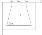
图2为本发明实施例提供的基于滑动窗的对称性检测示意图;Fig. 2 is a schematic diagram of a symmetry detection based on a sliding window provided by an embodiment of the present invention;
图3为本发明实施例提供的基于信息融合的前方车辆识别系统的结构示意图。Fig. 3 is a schematic structural diagram of a front vehicle recognition system based on information fusion provided by an embodiment of the present invention.
具体实施方式Detailed ways
下面对照附图,通过对实施例的描述,对本发明的具体实施方式作进一步详细的说明,以帮助本领域的技术人员对本发明的发明构思、技术方案有更完整、准确和深入的理解。The specific implementation of the present invention will be described in further detail below by describing the embodiments with reference to the accompanying drawings, so as to help those skilled in the art have a more complete, accurate and in-depth understanding of the inventive concepts and technical solutions of the present invention.
本发明基于神经网络预测图像中的车辆区域高度,通过滑动窗口对图像车辆区域进行对称性检测,将对称性最高的区域中心作为图像中车辆区域的中心,实现车辆区域在图像中的定位。The invention predicts the height of the vehicle area in the image based on the neural network, detects the symmetry of the image vehicle area through a sliding window, and uses the center of the area with the highest symmetry as the center of the vehicle area in the image to realize the positioning of the vehicle area in the image.
图1为本发明实施例提供的基于信息融合的前方车辆识别方法流程图,该方法具体如下:Fig. 1 is the flow chart of the front vehicle recognition method based on information fusion provided by the embodiment of the present invention, the method is specifically as follows:
步骤1:对相机进行内参标定,根据毫米波雷达与相机的位置关系标定外参,将毫米波雷达与相机进行联合标定,根据下式可以得到毫米波雷达坐标系与像素坐标系间的转换关系。Step 1: Calibrate the internal parameters of the camera, calibrate the external parameters according to the positional relationship between the millimeter-wave radar and the camera, and jointly calibrate the millimeter-wave radar and the camera. According to the following formula, the conversion relationship between the millimeter-wave radar coordinate system and the pixel coordinate system can be obtained .

其中,(Xr,Yr,Zr)为空间点在毫米波雷达坐标系中的坐标,(Xc,Yc,Zc)为空间点相机坐标系中的坐标,(u.v)为空间点像素坐标系中的坐标,R、T分别为毫米波雷达坐标系到相机坐标系的旋转矩阵、平移矩阵,根据毫米波雷达与相机的位置关系确定,(u0,v0)为光心的像素坐标,fx、fy分别为相机水平,竖直方向上归一化焦距,单位为像素,可根据相机内参标定结果确定,Zc是指相机坐标系距地面的高度。Among them, (Xr , Yr , Zr ) are the coordinates of the space point in the millimeter-wave radar coordinate system, (Xc , Yc , Zc ) are the coordinates of the space point in the camera coordinate system, and (uv) is the space point The coordinates in the point pixel coordinate system, R and T are the rotation matrix and translation matrix from the millimeter wave radar coordinate system to the camera coordinate system respectively, determined according to the positional relationship between the millimeter wave radar and the camera, (u0 , v0 ) is the optical center The pixel coordinates of , fx , fy are the normalized focal lengths of the camera in the horizontal and vertical directions respectively, and the unit is pixel, which can be determined according to the calibration results of the internal parameters of the camera. Zc refers to the height of the camera coordinate system from the ground.
步骤2:构建BP神经网络,采用三层BP反向神经网络,输入层包括两个神经元,对应输入毫米波雷达识别前方车辆的距离和相对角度信息,隐含层包括8个神经元,输出层包括应该神经元,对应输出图像车辆区域的尺寸信息。Step 2: Construct a BP neural network, using a three-layer BP reverse neural network. The input layer includes two neurons, which correspond to the input of millimeter-wave radar to identify the distance and relative angle information of the vehicle in front. The hidden layer includes 8 neurons, and the output The layer consists of neurons that correspond to the size information of the vehicle region in the output image.
前方车辆距离是指通过毫米波雷达所在车辆与前方车辆的距离,相对角度是指毫米波雷达所在车辆与前方车辆的相对角度,即毫米波雷达的检测角度。在本发明实施例中,BP神经网络预测过程具体步骤如下:The distance to the vehicle ahead refers to the distance between the vehicle where the millimeter-wave radar is located and the vehicle in front, and the relative angle refers to the relative angle between the vehicle where the millimeter-wave radar is located and the vehicle in front, that is, the detection angle of the millimeter-wave radar. In the embodiment of the present invention, the specific steps of the BP neural network prediction process are as follows:
步骤21:参数初始化:权重w采用均值为0、方差为0.01的高斯分布进行初始化,偏置b设置初始值为1,给定初始学习率η=0.1,给定ReLU激活函数如下:
步骤22:训练样本及测试样本的采集:通过采集n个毫米波雷达识别前方车辆的距离与角度信息和当前时刻下的相机图像,毫米波雷达采集前方车辆的距离x1与相对角度x2,其中X=(x1,x2),毫米波雷达采集前方车辆信息包括近距离、中距离、远距离和不同相对角度下车辆,对应标注车辆在相机采集图像中的高度y,其中y=(y1,y2,y3,...,yn)。Step 22: Collection of training samples and test samples: By collecting n millimeter-wave radars to identify the distance and angle information of the vehicle in front and the camera image at the current moment, the millimeter-wave radar collects the distance x1 and relative angle x2 of the vehicle in front, Where X=(x1 , x2 ), the millimeter-wave radar collects the vehicle information in front including short-distance, medium-distance, long-distance and vehicles at different relative angles, corresponding to the height y of the marked vehicle in the image collected by the camera, where y=( y1 ,y2 ,y3 ,...,yn ).
步骤23:网络训练:将采集到的毫米波雷达数据输入到BP神经网络中,利用下面公式求得隐含层输出aj和输出层输出

其中,wih为输入层与隐含层之间的权重,偏移量为bh;whi为隐含层与输出层之间的权重,偏移量为bj,i为输入层神经元个数;h为隐含层神经元个数;j为输出层神经元个数。Among them, wih is the weight between the input layer and the hidden layer, the offset is bh ; whi is the weight between the hidden layer and the output layer, the offset is bj , i is the input layer neuron number; h is the number of neurons in the hidden layer; j is the number of neurons in the output layer.
利用下式计算输出值

如下式,利用梯度下降法使误差E达到最小值:The following formula uses the gradient descent method to minimize the error E:


如下式,对权重进行更新:The weights are updated as follows:


判断样本误差E是否小于误差阈值err,若所有的样本误差E均小于误差阈值err,则BP神经网络训练结束;否则,继续BP神经网络训练过程,更新参数。Judging whether the sample error E is less than the error threshold err, if all the sample errors E are less than the error threshold err, the BP neural network training ends; otherwise, continue the BP neural network training process and update the parameters.
步骤24:BP神经网络预测:输入毫米波雷达检测到的前方车辆距离、相对于角度,通过步骤3训练好的BP神经网络,得到输出值即为前方车辆在图像中的高度,又称图像车辆区域高度。Step 24: BP neural network prediction: Input the distance and relative angle of the vehicle in front detected by the millimeter-wave radar, through the BP neural network trained in step 3, the output value obtained is the height of the vehicle in front in the image, also known as the image vehicle area height.
步骤3:根据道路交通相关法规,车辆的宽度约为高度的1.3倍,因此车辆识别区域的高度与宽度比例应为1:1.3,根据比例关系确定矩形车辆识别区域的大小,将毫米波雷达检测到的前方车辆的车辆坐标转换为像素坐标系下的像素坐标,以该像素坐标作为矩形车辆识别区域的中心点,初步确定矩形车辆识别区域在相机采集图像中的位置,假定车辆在图像的高度为H,那么宽度为1.3H,而车辆识别区域则是高度为H,宽度为1.3H的矩形区域,该矩形区域的中心即为毫米波雷达检测点在像素坐标系中的像素坐标。再将车辆识别区域的高和宽分别向外同比例扩展k倍,得到毫米波雷达的初始ROI区域,k参数的设置值,必须确保初始ROI区域中包含前方车辆图像。Step 3: According to relevant road traffic regulations, the width of a vehicle is about 1.3 times its height, so the ratio of height to width of the vehicle identification area should be 1:1.3, and the size of the rectangular vehicle identification area is determined according to the proportional relationship, and the millimeter-wave radar detection The vehicle coordinates of the vehicle ahead are converted into pixel coordinates in the pixel coordinate system, and the pixel coordinates are used as the center point of the rectangular vehicle recognition area to preliminarily determine the position of the rectangular vehicle recognition area in the image captured by the camera. Assuming that the vehicle is at the height of the image is H, then the width is 1.3H, and the vehicle identification area is a rectangular area with a height of H and a width of 1.3H. The center of the rectangular area is the pixel coordinate of the millimeter-wave radar detection point in the pixel coordinate system. Then expand the height and width of the vehicle recognition area by k times in the same proportion to obtain the initial ROI area of the millimeter-wave radar. The setting value of the k parameter must ensure that the initial ROI area contains the front vehicle image.
步骤4:对初始ROI区域内图像进行灰度处理、Sobel边缘检测、二值分割和概率霍夫直线拟合,拟合出车顶直线。车顶直线的提取方法具体包括如下步骤:Step 4: Perform grayscale processing, Sobel edge detection, binary segmentation and probabilistic Hough line fitting on the image in the initial ROI area to fit the roof line. The method for extracting the straight line of the roof specifically includes the following steps:
步骤41:将初始ROI区域内图像转换为灰度图像。Step 41: Convert the image in the initial ROI region into a grayscale image.
步骤42:对灰度图像进行Sobel算子运算,其中Sobel算子如下所示:Step 42: Perform Sobel operator operation on the grayscale image, where the Sobel operator is as follows:


其中,得到梯度大小G和梯度方向θ后,根据已设定的阈值确定图像边缘处像素点。Among them, after obtaining the gradient size G and the gradient direction θ, the pixel points at the edge of the image are determined according to the set threshold.
步骤43:对边缘检测后的图像利用最大类间方差求所述边缘检测后的图像的全局阈值,并灰度图像转换为含有背景和前景的二值图像。Step 43: Calculate the global threshold of the edge detected image by using the maximum inter-class variance, and convert the grayscale image into a binary image containing background and foreground.
步骤44:采用概率霍夫变换,通过设置累加平面为20、最小直线长度为10个像素和线段最大间隔为2个像素,拟合出二值图像中车辆的顶部轮廓直线,称为车顶拟合直线,并且得到车顶拟合直线上拟合像素的坐标。Step 44: Using the probabilistic Hough transform, by setting the accumulation plane to 20, the minimum line length to 10 pixels, and the maximum line segment interval to 2 pixels, fit the top contour line of the vehicle in the binary image, which is called the roof approximation Fit the straight line, and get the coordinates of the fitted pixels on the fitted straight line on the roof.
步骤5:以初始ROI区域为滑动窗,滑动窗沿水平方向分别向左和向右平移m个像素点,并且设置滑动窗的滑动步长为n个像素点,可以生成(2×m)/n+1个候选ROI区域,如图2所示;Step 5: Taking the initial ROI area as the sliding window, the sliding window is translated to the left and right by m pixels in the horizontal direction, and the sliding step of the sliding window is set to n pixels, which can generate (2×m)/n +1 candidate ROI area, as shown in Figure 2;
步骤6:获取车顶拟合直线左侧端点坐标Uleft和右侧端点坐标Uright,如图2所示,计算出车顶拟合直线的中间点坐标Umid为:Step 6: Obtain the coordinates Uleft of the left end point of the fitting line of the car roof and the coordinates Uright of the right end point of the straight line, as shown in Figure 2, and calculate the coordinate Umid of the middle point of the fitting line of the car roof as follows:

最后,可以得到车顶拟合直线中间点与各候选ROI区域中心Q的距离,此距离用来衡量车辆位置在候选ROI区域内的对称度sym,如下式:Finally, the distance between the middle point of the roof fitting line and the center Q of each candidate ROI area can be obtained, which is used to measure the symmetry sym of the vehicle position in the candidate ROI area, as follows:
sym=|UQ-Umid|sym=|UQ -Umid |
其中,UQ为候选ROI区域中心点Q的坐标,通过上式该对称性问题及转换为求解sym的最小值symmin,其中最小值处的候选ROI区域包含车辆轮廓对称性最优,再根据BP神经网络输出的车辆识别区域高度和宽度,创建最佳矩形车辆识别区域。该位置实现了毫米波雷达识别信息与图像信息最优匹配。Among them, UQ is the coordinate of the center point Q of the candidate ROI area. Through the above formula, the symmetry problem is transformed into the minimum value symmin for solving sym, where the candidate ROI area at the minimum value contains the optimal symmetry of the vehicle contour, and then according to The height and width of the vehicle identification area output by the BP neural network create an optimal rectangular vehicle identification area. This position realizes the optimal matching of millimeter-wave radar identification information and image information.
图3为本发明实施例提供的基于信息融合的前方车辆识别系统的结构示意图,为了便于说明,仅示出于本发明实施例相关的部分,该系统包括:Fig. 3 is a schematic structural diagram of the front vehicle recognition system based on information fusion provided by the embodiment of the present invention. For the convenience of description, only the relevant parts of the embodiment of the present invention are shown. The system includes:
毫米波雷达及相机,毫米波雷达安装在车辆前方保险杠处,相机位于毫米波雷达的上方;Millimeter wave radar and camera, the millimeter wave radar is installed at the front bumper of the vehicle, and the camera is located above the millimeter wave radar;
数据处理单元,与毫米波雷达及相机连接,数据处理单元上集成有BP神经网络,数据处理单元基于上述基于信息融合的前方车辆识别方法将车辆识别区域定位到相机所拍摄的图像中。The data processing unit is connected with the millimeter-wave radar and the camera. The data processing unit is integrated with a BP neural network. The data processing unit locates the vehicle recognition area in the image captured by the camera based on the above-mentioned information fusion-based front vehicle recognition method.
本发明的有益效果具体如下:The beneficial effects of the present invention are specifically as follows:
通过BP神经网络较准确的预测图像中不同角度和距离的车辆高度,通过对毫米波雷达的ROI区域使用图像处理方法,能够在不同场景下较好的拟合出车顶直线,使用滑动窗口技术,得到车辆对称性最好的车辆识别区域,通过融合图像信息减少毫米波雷达的识别误差,将毫米波雷达信息准确的与采集图像信息匹配,实现了车辆在图像中的精准定位,提高多传感器融合的精度。The BP neural network can accurately predict the height of the vehicle at different angles and distances in the image. By using the image processing method for the ROI area of the millimeter-wave radar, it can better fit the roof line in different scenarios. Using the sliding window technology , get the vehicle recognition area with the best symmetry of the vehicle, reduce the recognition error of the millimeter-wave radar by fusing the image information, and accurately match the millimeter-wave radar information with the collected image information, realize the precise positioning of the vehicle in the image, and improve the multi-sensor Fusion accuracy.
上面结合附图对本发明进行了示例性描述,显然本发明具体实现并不受上述方式的限制,只要采用了本发明的方法构思和技术方案进行的各种非实质性的改进,或未经改进将本发明的构思和技术方案直接应用于其它场合的,均在本发明的保护范围之内。The present invention has been exemplarily described above in conjunction with the accompanying drawings. Obviously, the specific implementation of the present invention is not limited by the above-mentioned method, as long as various insubstantial improvements are adopted in the method concept and technical solutions of the present invention, or there is no improvement Directly applying the conception and technical solutions of the present invention to other occasions falls within the protection scope of the present invention.
Claims (6)
Translated fromChinesePriority Applications (1)
| Application Number | Priority Date | Filing Date | Title |
|---|---|---|---|
| CN202110635324.2ACN113313041B (en) | 2021-06-08 | 2021-06-08 | Front vehicle recognition method and system based on information fusion |
Applications Claiming Priority (1)
| Application Number | Priority Date | Filing Date | Title |
|---|---|---|---|
| CN202110635324.2ACN113313041B (en) | 2021-06-08 | 2021-06-08 | Front vehicle recognition method and system based on information fusion |
Publications (2)
| Publication Number | Publication Date |
|---|---|
| CN113313041A CN113313041A (en) | 2021-08-27 |
| CN113313041Btrue CN113313041B (en) | 2022-11-15 |
Family
ID=77378026
Family Applications (1)
| Application Number | Title | Priority Date | Filing Date |
|---|---|---|---|
| CN202110635324.2AActiveCN113313041B (en) | 2021-06-08 | 2021-06-08 | Front vehicle recognition method and system based on information fusion |
Country Status (1)
| Country | Link |
|---|---|
| CN (1) | CN113313041B (en) |
Families Citing this family (1)
| Publication number | Priority date | Publication date | Assignee | Title |
|---|---|---|---|---|
| CN114624683B (en)* | 2022-04-07 | 2024-07-19 | 苏州知至科技有限公司 | Calibration method for external rotating shaft of laser radar |
Citations (2)
| Publication number | Priority date | Publication date | Assignee | Title |
|---|---|---|---|---|
| CN103324936A (en)* | 2013-05-24 | 2013-09-25 | 北京理工大学 | Vehicle lower boundary detection method based on multi-sensor fusion |
| CN105223583A (en)* | 2015-09-10 | 2016-01-06 | 清华大学 | A kind of target vehicle course angle computing method based on three-dimensional laser radar |
Family Cites Families (10)
| Publication number | Priority date | Publication date | Assignee | Title |
|---|---|---|---|---|
| CN103226833B (en)* | 2013-05-08 | 2015-08-05 | 清华大学 | A kind of point cloud data segmentation method based on three-dimensional laser radar |
| CN104392212B (en)* | 2014-11-14 | 2017-09-01 | 北京工业大学 | A Vision-Based Road Information Detection and Front Vehicle Recognition Method |
| CN104637059A (en)* | 2015-02-09 | 2015-05-20 | 吉林大学 | Night preceding vehicle detection method based on millimeter-wave radar and machine vision |
| CN105574542A (en)* | 2015-12-15 | 2016-05-11 | 中国北方车辆研究所 | Multi-vision feature vehicle detection method based on multi-sensor fusion |
| CN106951879B (en)* | 2017-03-29 | 2020-04-14 | 重庆大学 | Multi-feature fusion vehicle detection method based on camera and millimeter wave radar |
| CN107609522B (en)* | 2017-09-19 | 2021-04-13 | 东华大学 | An information fusion vehicle detection system based on lidar and machine vision |
| CN108037505A (en)* | 2017-12-08 | 2018-05-15 | 吉林大学 | A method and system for detecting vehicles ahead at night |
| CN108764108A (en)* | 2018-05-22 | 2018-11-06 | 湖北省专用汽车研究院 | A kind of Foregut fermenters method based on Bayesian inference |
| KR102069843B1 (en)* | 2018-08-31 | 2020-01-23 | 서강대학교 산학협력단 | Apparatus amd method for tracking vehicle |
| CN111368706B (en)* | 2020-03-02 | 2023-04-18 | 南京航空航天大学 | Data fusion dynamic vehicle detection method based on millimeter wave radar and machine vision |
- 2021
- 2021-06-08CNCN202110635324.2Apatent/CN113313041B/enactiveActive
Patent Citations (2)
| Publication number | Priority date | Publication date | Assignee | Title |
|---|---|---|---|---|
| CN103324936A (en)* | 2013-05-24 | 2013-09-25 | 北京理工大学 | Vehicle lower boundary detection method based on multi-sensor fusion |
| CN105223583A (en)* | 2015-09-10 | 2016-01-06 | 清华大学 | A kind of target vehicle course angle computing method based on three-dimensional laser radar |
Also Published As
| Publication number | Publication date |
|---|---|
| CN113313041A (en) | 2021-08-27 |
Similar Documents
| Publication | Publication Date | Title |
|---|---|---|
| CN112740225B (en) | A kind of pavement element determination method and device | |
| CN109490890B (en) | A smart car-oriented millimeter wave radar and monocular camera information fusion method | |
| CN108960183B (en) | Curve target identification system and method based on multi-sensor fusion | |
| CN102682292B (en) | Road edge detection and rough positioning method based on monocular vision | |
| Wijesoma et al. | Road-boundary detection and tracking using ladar sensing | |
| CN103065323B (en) | Subsection space aligning method based on homography transformational matrix | |
| CN101929867B (en) | Clear path detection using road model | |
| CN109085570A (en) | Automobile detecting following algorithm based on data fusion | |
| CN103176185B (en) | Method and system for detecting road barrier | |
| CN107632308B (en) | Method for detecting contour of obstacle in front of vehicle based on recursive superposition algorithm | |
| CN112363167A (en) | Extended target tracking method based on fusion of millimeter wave radar and monocular camera | |
| CN111369541A (en) | Vehicle detection method for intelligent automobile under severe weather condition | |
| US20080089557A1 (en) | Image processing apparatus, image processing method, and computer program product | |
| CN106096525A (en) | A kind of compound lane recognition system and method | |
| CN115187964A (en) | Automatic driving decision-making method based on multi-sensor data fusion and SoC chip | |
| CN113611008B (en) | Vehicle driving scene acquisition method, device, equipment and medium | |
| CN116403186B (en) | FPN Swin Transformer and Pointnet ++ based automatic driving three-dimensional target detection method | |
| CN114973195A (en) | Vehicle tracking method, device and system based on multi-information fusion | |
| CN112232139A (en) | Obstacle avoidance method based on combination of Yolo v4 and Tof algorithm | |
| CN117173666B (en) | Automatic driving target identification method and system for unstructured road | |
| CN113111707A (en) | Preceding vehicle detection and distance measurement method based on convolutional neural network | |
| Hussain et al. | Multiple objects tracking using radar for autonomous driving | |
| CN117496467A (en) | Special-shaped lane line detection method based on fusion of monocular camera and 3D LIDAR | |
| CN113313041B (en) | Front vehicle recognition method and system based on information fusion | |
| CN119312276A (en) | A human-vehicle interaction identification method and system |
Legal Events
| Date | Code | Title | Description |
|---|---|---|---|
| PB01 | Publication | ||
| PB01 | Publication | ||
| SE01 | Entry into force of request for substantive examination | ||
| SE01 | Entry into force of request for substantive examination | ||
| GR01 | Patent grant | ||
| GR01 | Patent grant |