CN113289137B - Implantable medical device based on self-sealing sealing plug structure - Google Patents
Implantable medical device based on self-sealing sealing plug structureDownload PDFInfo
- Publication number
- CN113289137B CN113289137BCN202110565081.XACN202110565081ACN113289137BCN 113289137 BCN113289137 BCN 113289137BCN 202110565081 ACN202110565081 ACN 202110565081ACN 113289137 BCN113289137 BCN 113289137B
- Authority
- CN
- China
- Prior art keywords
- self
- guide
- sealing
- medical device
- sealing plug
- Prior art date
- Legal status (The legal status is an assumption and is not a legal conclusion. Google has not performed a legal analysis and makes no representation as to the accuracy of the status listed.)
- Expired - Fee Related
Links
Images


Classifications
- A—HUMAN NECESSITIES
- A61—MEDICAL OR VETERINARY SCIENCE; HYGIENE
- A61M—DEVICES FOR INTRODUCING MEDIA INTO, OR ONTO, THE BODY; DEVICES FOR TRANSDUCING BODY MEDIA OR FOR TAKING MEDIA FROM THE BODY; DEVICES FOR PRODUCING OR ENDING SLEEP OR STUPOR
- A61M5/00—Devices for bringing media into the body in a subcutaneous, intra-vascular or intramuscular way; Accessories therefor, e.g. filling or cleaning devices, arm-rests
- A61M5/14—Infusion devices, e.g. infusing by gravity; Blood infusion; Accessories therefor
- A61M5/142—Pressure infusion, e.g. using pumps
- A61M5/145—Pressure infusion, e.g. using pumps using pressurised reservoirs, e.g. pressurised by means of pistons
- A61M5/155—Pressure infusion, e.g. using pumps using pressurised reservoirs, e.g. pressurised by means of pistons pressurised by gas introduced into the reservoir
- A—HUMAN NECESSITIES
- A61—MEDICAL OR VETERINARY SCIENCE; HYGIENE
- A61M—DEVICES FOR INTRODUCING MEDIA INTO, OR ONTO, THE BODY; DEVICES FOR TRANSDUCING BODY MEDIA OR FOR TAKING MEDIA FROM THE BODY; DEVICES FOR PRODUCING OR ENDING SLEEP OR STUPOR
- A61M2205/00—General characteristics of the apparatus
- A61M2205/33—Controlling, regulating or measuring
- A61M2205/3331—Pressure; Flow
Landscapes
- Health & Medical Sciences (AREA)
- Vascular Medicine (AREA)
- Engineering & Computer Science (AREA)
- Anesthesiology (AREA)
- Biomedical Technology (AREA)
- Heart & Thoracic Surgery (AREA)
- Hematology (AREA)
- Life Sciences & Earth Sciences (AREA)
- Animal Behavior & Ethology (AREA)
- General Health & Medical Sciences (AREA)
- Public Health (AREA)
- Veterinary Medicine (AREA)
- Prostheses (AREA)
Abstract
Translated fromChinese
Description
Translated fromChinese技术领域technical field
本发明涉及医疗应用技术领域,具体为基于自密封性密封塞结构的植入式医疗装置。The invention relates to the technical field of medical applications, in particular to an implantable medical device based on a self-sealing sealing plug structure.
背景技术Background technique
植入式医疗装置主要用于需要长期定时输液的病患,在特种病情时会设置在人体内,为医疗提供方便;植入式医疗装置,广泛应用于治疗神经系统、心脏系统等疾病。植入式医疗装置包括脑深部电刺激,植入式脑皮层刺激,植入式脊髓电刺激,植入式骶神经电刺激,植入式迷走神经电刺激、植入式心脏电刺激系统(俗称心脏起搏器)、植入式药物输注系统等。Implantable medical devices are mainly used for patients who need long-term regular infusion. In special cases, they will be installed in the human body to provide convenience for medical treatment. Implantable medical devices are widely used in the treatment of diseases such as the nervous system and the cardiac system. Implantable medical devices include deep brain stimulation, implantable cerebral cortex stimulation, implantable spinal cord stimulation, implantable sacral nerve stimulation, implantable vagus nerve stimulation, and implantable cardiac electrical stimulation system (commonly known as cardiac electrical stimulation system). pacemaker), implantable drug infusion systems, etc.
经过检索例如专利号为CN211214989U的专利公开了一种植入式医疗装置用自密封性密封塞结构,包括成型在刺激器连接头部分的安装孔、第一密封环、压紧件及第二密封环,通过压紧件使第一密封环产生沿所述安装孔径向的压力,使所述第二密封环产生平行于所述安装孔轴向的压力,从而实现对安装孔内壁的密封。本实施例的自密封性密封塞结构无需再依赖螺钉的结构,能在螺钉处提供的密封的基础上,再增加一道密封。而且整个结构无需涂胶,可节约装配时间;材料及结构适应性好,对人体无害;密封性好,不易受损,可延长植入式医疗装置的使用寿命。After searching, for example, the patent No. CN211214989U discloses a self-sealing sealing plug structure for an implantable medical device, which includes a mounting hole formed in the connector part of the stimulator, a first sealing ring, a pressing member and a second sealing ring , through the pressing member, the first sealing ring generates pressure along the axial direction of the mounting hole, and the second sealing ring generates pressure parallel to the axial direction of the mounting hole, so as to seal the inner wall of the mounting hole. The self-sealing sealing plug structure of this embodiment does not need to rely on the structure of the screw, and can add another seal on the basis of the sealing provided by the screw. Moreover, the whole structure does not need to be glued, which can save assembly time; the material and structure have good adaptability and are harmless to the human body;
但是,目前使用的医疗装置主要通过螺纹结构组装并收纳在体内,不具备针对局部血管进行快速药液注入的功能,不具备根据需要快速换药补药的功能,不具备快捷的药液流向控制组件,不利于自主输液,因此,不满足现有的需求,对此我们提出了基于自密封性密封塞结构的植入式医疗装置。However, the currently used medical devices are mainly assembled and stored in the body through a threaded structure, and do not have the function of rapid injection of medicinal liquid into local blood vessels, the function of rapidly changing and replenishing medicines as needed, and the rapid flow of medicinal liquids to control components. , is not conducive to autonomous infusion, therefore, does not meet the existing needs, for which we propose an implantable medical device based on a self-sealing sealing plug structure.
发明内容SUMMARY OF THE INVENTION
(一)技术问题(1) Technical problems
本发明的目的在于提供基于自密封性密封塞结构的植入式医疗装置,以解决上述背景技术中提出的目前使用的医疗装置主要通过螺纹结构组装并收纳在体内,不具备针对局部血管进行快速药液注入的功能,不具备根据需要快速换药补药的功能,不具备快捷的药液流向控制组件,不利于自主输液的问题。The purpose of the present invention is to provide an implantable medical device based on a self-sealing sealing plug structure, so as to solve the problem that the medical device currently used is mainly assembled and stored in the body through a threaded structure as proposed in the above-mentioned background art, and does not have the ability to quickly The function of liquid medicine injection does not have the function of quickly changing medicines and replenishing medicines as needed, and it does not have the fast flow of liquid medicine to the control component, which is not conducive to the problem of autonomous infusion.
(二)技术方案(2) Technical solutions
为实现上述目的,本发明提供如下技术方案:基于自密封性密封塞结构的植入式医疗装置,包括血管植壳A;In order to achieve the above object, the present invention provides the following technical solutions: an implantable medical device based on a self-sealing sealing plug structure, including a vascular graft shell A;
血管植壳B,呈半圆柱筒结构,其与血管植壳A形状一致,且血管植壳A和血管植壳B能够通过螺栓固定连接;血管植壳B的外侧中间一体式设置有导针管;The vascular grafting shell B has a semi-cylindrical structure, which is consistent with the shape of the vascular grafting shell A, and the vascular grafting shell A and the vascular grafting shell B can be fixedly connected by bolts; the outer middle of the vascular grafting shell B is integrally provided with a needle guide tube;
滑排,主体为圆环结构,中间设置四组凸条固定连接,滑排的两端外侧设置为凸缘结构,滑排滑动设置于导针管的外侧;The sliding block has a ring structure in its main body, four sets of protruding strips are fixedly connected in the middle, the outer sides of the two ends of the sliding block are set as flange structures, and the sliding block is slidably arranged on the outer side of the needle guide tube;
医用贴条,滑动设置于导针管的外侧;The medical sticker is slidably arranged on the outside of the needle guide tube;
控仓,主体为方壳结构,控仓的一侧连接设置有束缚带。The main body of the control warehouse is a square shell structure, and one side of the control warehouse is connected with a restraint belt.
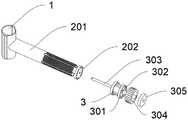
优选的,所述血管植壳B还包括有密封塞;导针管的外端设置有凹陷螺纹结构,且凹陷螺纹结构外侧开设有四组方槽;导针管的中间固定设置有密封塞;滑排滑动设置于导针管的凹陷螺纹结构外部。Preferably, the blood vessel grafting shell B further includes a sealing plug; the outer end of the guide tube is provided with a concave thread structure, and four sets of square grooves are formed on the outer side of the concave thread structure; the middle of the guide tube is fixedly provided with a sealing plug; It is slidably arranged outside the concave thread structure of the needle guide tube.
优选的,所述滑排包括有中间套、单向阀A、输入针、旋母和端盖;滑排的凸条滑动设置于导针管的方槽中;滑排的中间固定设置有中间套,中间套的中间固定设置有单向阀A;单向阀A的一端固定设置有输入针,且输入针与密封塞滑动连接;滑排的外侧旋转设置有旋母;滑排的外端中间固定设置有端盖。Preferably, the sliding row includes an intermediate sleeve, a one-way valve A, an input needle, a screw nut and an end cover; the protruding strip of the sliding row is slidably arranged in the square groove of the needle guide tube; the middle of the sliding row is fixedly provided with an intermediate sleeve , a check valve A is fixed in the middle of the middle sleeve; an input needle is fixed at one end of the check valve A, and the input needle is slidably connected with the sealing plug; the outer side of the sliding row is rotated with a screw nut; A fixed end cap is provided.
优选的,所述单向阀A还包括有输送管和导向片;单向阀A的外侧连接设置有输送管,输送管的外部一体式设置有两组导向片;导向片的中间开设有方孔结构;两组导向片之间设置有自锁阀。Preferably, the one-way valve A further includes a conveying pipe and a guide sheet; the outer side of the one-way valve A is connected with a conveying pipe, and the outside of the conveying pipe is integrally provided with two sets of guide sheets; the middle of the guide sheet is provided with a square Hole structure; a self-locking valve is arranged between the two sets of guide plates.
优选的,所述医用贴条还包括有药棉;医用贴条的中间一侧固定设置有T形圆套,医用贴条的另一侧中间粘贴设置有药棉,且T形圆套滑动设置于导针管的外侧。Preferably, the medical sticker further includes cotton wool; a T-shaped round sleeve is fixedly arranged on one side of the middle of the medical sticker, and a cotton wool is pasted in the middle of the other side of the medical sticker, and the T-shaped round sleeve is slidably arranged on the guide outside of the needle.
优选的,所述控仓还包括有螺纹塞、输气管和单向阀B;控仓的底部中间固定设置有螺纹塞,螺纹塞的中间固定设置有输气管,输送管的底端固定设置于螺纹塞的中间;输气管的顶部连接设置有单向阀B,单向阀B的一端设置有锥形斗;控仓的外侧固定设置有气仓,且单向阀B的锥形斗与气仓连接相通;控仓的底部一体式设置有螺纹筒结构,且螺纹筒结构的外端固定设置有药筒。Preferably, the control bin further includes a threaded plug, a gas delivery pipe and a one-way valve B; a threaded plug is fixedly arranged in the middle of the bottom of the control bin, a gas delivery pipe is fixedly arranged in the middle of the threaded plug, and the bottom end of the delivery pipe is fixedly arranged on the The middle of the threaded plug; the top of the gas pipeline is connected with a check valve B, and one end of the check valve B is provided with a conical bucket; the outer side of the control bin is fixed with an air bin, and the conical bucket of the check valve B is connected to the gas The silo is connected and communicated; the bottom of the control silo is integrally provided with a threaded barrel structure, and the outer end of the threaded barrel structure is fixedly provided with a drug cartridge.
优选的,所述气仓还包括有活塞盘、单向阀C、过滤棉柱、端片和环网;气仓的主体为圆筒状结构,活塞盘的内部滑动设置有活塞盘,活塞盘的一侧中间一体式设置有圆筒结构,圆筒结构内部固定设置有单向阀C和过滤棉柱;气仓的圆筒结构外端通过两组连接柱固定设置有端片,端片和气仓的圆筒结构之间外部固定设置有环网;气仓的容积小于药筒。Preferably, the air chamber further includes a piston disc, a one-way valve C, a filter cotton column, an end piece and a ring net; the main body of the air chamber is a cylindrical structure, and a piston disc is slidably arranged inside the piston disc. A cylindrical structure is integrally arranged in the middle of one side of the air chamber, and a one-way valve C and a filter cotton column are fixed inside the cylindrical structure; the outer end of the cylindrical structure of the air silo is fixedly provided with end pieces through two sets of connecting columns. A ring net is fixed externally between the cylindrical structures of the silo; the volume of the air silo is smaller than that of the medicine cartridge.
优选的,所述自锁阀还包括有架块、导柱、压片、弹簧环槽A、弹簧环槽B和导向条;架块的数量设置为两组,架块的一侧固定设置有两组导柱,架块通过两组导柱错位穿设滑动连接;导柱的另一端固定设置有压片;架块的外侧中间开设有弹簧环槽A,压片的内侧开设有弹簧环槽B,弹簧环槽A和弹簧环槽B之间设置有弹簧;架块和压片的外侧固定设置有四组导向条,导向条均穿过导向片滑动连接。Preferably, the self-locking valve further includes a frame block, a guide post, a pressing piece, a spring ring groove A, a spring ring groove B and a guide strip; the number of the frame blocks is set to two groups, and one side of the frame block is fixedly provided with There are two sets of guide posts, and the frame block is staggered through the two sets of guide posts to slide and connect; the other end of the guide post is fixedly provided with a pressing piece; the outer middle of the frame block is provided with a spring ring groove A, and the inner side of the pressing piece is provided with a spring ring groove B. A spring is arranged between the spring ring groove A and the spring ring groove B; four sets of guide strips are fixedly arranged on the outside of the frame block and the pressing piece, and the guide strips are all slidably connected through the guide pieces.
(三)有益效果(3) Beneficial effects
本发明提供了基于自密封性密封塞结构的植入式医疗装置,通过设置有血管植壳A和血管植壳B,能够提供针对局部血管进行快速药液注入的功能,在药筒内输入药液,然后安装药筒;拉开活塞盘,在气仓的内部产生负压,然后外部空气穿过环网和过滤棉柱的双重过滤进入气仓中,然后推进活塞盘,活塞盘将气仓内部的气体穿过单向阀B输入药筒中进行增压,有利于快速输液,并且能够根据需要快速换药补药。The present invention provides an implantable medical device based on a self-sealing sealing plug structure. By being provided with a vascular grafting shell A and a vascular grafting shell B, it can provide the function of rapid drug liquid injection for local blood vessels, and the drug can be injected into the cartridge. Then install the cartridge; pull the piston disc to generate negative pressure inside the air chamber, then the external air enters the air chamber through the double filtration of the ring net and the filter cotton column, and then pushes the piston disc, the piston disc pushes the air chamber The internal gas is fed into the cartridge through the one-way valve B for pressurization, which is conducive to rapid infusion, and can be quickly changed and replenished as needed.
其次,自锁阀的设置,为医疗装置提供了快捷的药液流向控制功能,按压两组压片,将两组压片和架块合并,弹簧环槽A和弹簧环槽B的弹簧锁紧,将两组架块松开,药筒内的药液穿过输送管、单向阀A和输入针输入人体血管中,实现药物的注入,以便后续医疗;在完成输液后反转旋母将滑排复位,抽出输入针以便再次使用,输入针能够通过拆卸滑排进行更换。Secondly, the setting of the self-locking valve provides the medical device with a quick control function of the flow direction of the liquid medicine. Press the two sets of pressing tablets to combine the two sets of pressing tablets and the frame block, and the springs of the spring ring groove A and the spring ring groove B are locked. , loosen the two sets of frame blocks, and the medicinal liquid in the cartridge is input into the human blood vessels through the delivery tube, the one-way valve A and the input needle, so as to realize the injection of the medicine for subsequent medical treatment; The slide is reset, the input pin is pulled out for reuse, and the input pin can be replaced by removing the slide.
再者,旋母的设置,为医疗装置提供了方便的控制功能,旋转旋母,旋母带动滑排移动,滑排配合中间套在导针管中移动,将输入针插入人体血管,有利于自主输液。Furthermore, the arrangement of the rotary female provides a convenient control function for the medical device. The rotary female drives the sliding row to move, and the sliding row cooperates with the middle sleeve to move in the needle guide tube to insert the input needle into the human blood vessel, which is conducive to autonomous infusion. .
附图说明Description of drawings
图1为本发明实施例中的总体立体结构示意图;1 is a schematic diagram of an overall three-dimensional structure in an embodiment of the present invention;
图2为本发明实施例中的总体轴侧结构示意图;FIG. 2 is a schematic diagram of an overall axial side structure in an embodiment of the present invention;
图3为本发明实施例中的局部剖视结构示意图;3 is a partial cross-sectional structural schematic diagram in an embodiment of the present invention;
图4为本发明实施例中控仓的剖视结构示意图;4 is a schematic cross-sectional structural diagram of a control bin in an embodiment of the present invention;
图5为本发明实施例中气仓的剖视结构示意图;Fig. 5 is the sectional structure schematic diagram of the gas warehouse in the embodiment of the present invention;
图6为本发明实施例中自锁阀的立体结构示意图;FIG. 6 is a schematic three-dimensional structure diagram of a self-locking valve in an embodiment of the present invention;
图7为本发明实施例中的局部拆解结构示意图;7 is a schematic diagram of a partially disassembled structure in an embodiment of the present invention;
图8为本发明实施例中血管植壳B的立体结构示意图;8 is a schematic three-dimensional structural diagram of a blood vessel grafting shell B in an embodiment of the present invention;
在图1至图8中,部件名称或线条与附图编号的对应关系为:In Figures 1 to 8, the corresponding relationship between component names or lines and drawing numbers is:
1、血管植壳A;2、血管植壳B;201、导针管;202、密封塞;3、滑排;301、中间套;302、单向阀A;3021、输送管;3022、导向片;303、输入针;304、旋母;305、端盖;4、医用贴条;401、药棉;5、控仓;501、束缚带;502、螺纹塞;503、输气管;504、单向阀B;6、药筒;7、气仓;701、活塞盘;702、单向阀C;703、过滤棉柱;704、端片;705、环网;8、自锁阀;801、架块;802、导柱;803、压片;804、弹簧环槽A;805、弹簧环槽B;806、导向条。1. Vascular grafting A; 2. Vascular grafting B; 201. Needle tube; 202. Sealing plug; 3. Sliding row; 301. Intermediate sleeve; 302. Check valve A; ;303, input needle; 304, screw nut; 305, end cap; 4, medical sticker; 401, cotton wool; 5, control warehouse; 501, restraint belt; 502, threaded plug; 503, air tube; 504, one-way Valve B; 6, Cartridge; 7, Air Tank; 701, Piston disc; 702, Check valve C; 703, Filter cotton column; 704, End piece; 705, Ring net; 8, Self-locking valve; 801, Rack block; 802, guide post; 803, pressing piece; 804, spring ring groove A; 805, spring ring groove B; 806, guide strip.
具体实施方式Detailed ways
下面将结合本发明实施例中的附图,对本发明实施例中的技术方案进行清楚、完整地描述,显然,所描述的实施例仅仅是本发明一部分实施例,而不是全部的实施例。The technical solutions in the embodiments of the present invention will be clearly and completely described below with reference to the accompanying drawings in the embodiments of the present invention. Obviously, the described embodiments are only a part of the embodiments of the present invention, but not all of the embodiments.
请参阅图1至图8,本发明提供的一种实施例:基于自密封性密封塞结构的植入式医疗装置,包括血管植壳A1;血管植壳B2,呈半圆柱筒结构,其与血管植壳A1形状一致,且血管植壳A1和血管植壳B2能够通过螺栓固定连接;血管植壳B2的外侧中间一体式设置有导针管201;滑排3,主体为圆环结构,中间设置四组凸条固定连接,滑排3的两端外侧设置为凸缘结构,滑排3滑动设置于导针管201的外侧;医用贴条4,滑动设置于导针管201的外侧;血管植壳B2还包括有密封塞202;导针管201的外端设置有凹陷螺纹结构,且凹陷螺纹结构外侧开设有四组方槽;导针管201的中间固定设置有密封塞202;滑排3滑动设置于导针管201的凹陷螺纹结构外部;滑排3、中间套301、单向阀A302、输入针303、旋母304和端盖305;滑排3的凸条滑动设置于导针管201的方槽中;滑排3的中间固定设置有中间套301,中间套301的中间固定设置有单向阀A302;单向阀A302的一端固定设置有输入针303,且输入针303与密封塞202滑动连接;滑排3的外侧旋转设置有旋母304,旋母304与导针管201的外部凹陷螺纹结构螺纹连接;滑排3的外端中间固定设置有端盖305;单向阀A302还包括有输送管3021和导向片3022;单向阀A302的外侧连接设置有输送管3021,输送管3021的外部一体式设置有两组导向片3022;导向片3022的中间开设有方孔结构;医用贴条4还包括有药棉401;医用贴条4的中间一侧固定设置有T形圆套,医用贴条4的另一侧中间粘贴设置有药棉401,且T形圆套滑动设置于导针管201的外侧;两组导向片3022之间设置有自锁阀8;控仓5,主体为方壳结构,控仓5的一侧连接设置有束缚带501;控仓5还包括有螺纹塞502、输气管503和单向阀B504;控仓5的底部中间固定设置有螺纹塞502,螺纹塞502的中间固定设置有输气管503,输送管3021的底端固定设置于螺纹塞502的中间;输气管503的顶部连接设置有单向阀B504,单向阀B504的一端设置有锥形斗;控仓5的外侧固定设置有气仓7,且单向阀B504的锥形斗与气仓7连接相通;控仓5的底部一体式设置有螺纹筒结构,且螺纹筒结构的外端固定设置有药筒6。Please refer to FIG. 1 to FIG. 8, an embodiment provided by the present invention: an implantable medical device based on a self-sealing sealing plug structure, including a vascular graft shell A1; The vascular grafting shell A1 has the same shape, and the vascular grafting shell A1 and the vascular grafting shell B2 can be fixedly connected by bolts; the outer middle of the vascular grafting shell B2 is integrally provided with a
其中,气仓7还包括有活塞盘701、单向阀C702、过滤棉柱703、端片704和环网705;气仓7的主体为圆筒状结构,活塞盘701的内部滑动设置有活塞盘701,活塞盘701的一侧中间一体式设置有圆筒结构,圆筒结构内部固定设置有单向阀C702和过滤棉柱703;气仓7的圆筒结构外端通过两组连接柱固定设置有端片704,端片704和气仓7的圆筒结构之间外部固定设置有环网705;气仓7的容积小于药筒6。The
其中,自锁阀8还包括有架块801、导柱802、压片803、弹簧环槽A804、弹簧环槽B805和导向条806;架块801的数量设置为两组,架块801的一侧固定设置有两组导柱802,架块801通过两组导柱802错位穿设滑动连接;导柱802的另一端固定设置有压片803;架块801的外侧中间开设有弹簧环槽A804,压片803的内侧开设有弹簧环槽B805,弹簧环槽A804和弹簧环槽B805之间设置有弹簧;架块801和压片803的外侧固定设置有四组导向条806,导向条806均穿过导向片3022滑动连接。Among them, the self-locking
工作原理:使用时,先将医用贴条4固定在病患的创口处,将血管植壳A1和血管植壳B2组合安装在血管的外部,将束缚带501绑定在病患胳膊外;在药筒6内输入药液,然后安装药筒6;拉开活塞盘701,在气仓7的内部产生负压,然后外部空气穿过环网705和过滤棉柱703的双重过滤进入气仓7中,然后推进活塞盘701,活塞盘701将气仓7内部的气体穿过单向阀B504输入药筒6中进行增压。Working principle: When using, first fix the
旋转旋母304,旋母304带动滑排3移动,滑排3配合中间套301在导针管201中移动,将输入针303插入人体血管。Rotating the
按压两组压片803,将两组压片803和架块801合并,弹簧环槽A804和弹簧环槽B805的弹簧锁紧,将两组架块801松开,药筒6内的药液穿过输送管3021、单向阀A302和输入针303输入人体血管中,实现药物的注入,以便后续医疗;在完成输液后反转旋母304将滑排3复位,抽出输入针303以便再次使用,输入针303能够通过拆卸滑排3进行更换。Press the two sets of
对于本领域技术人员而言,显然本发明不限于上述示范性实施例的细节,而且在不背离本发明的精神或基本特征的情况下,能够以其他的具体形式实现本发明。因此,无论从哪一点来看,均应将实施例看作是示范性的,而且是非限制性的,本发明的范围由所附权利要求而不是上述说明限定,因此旨在将落在权利要求的等同要件的含义和范围内的所有变化囊括在本发明内。不应将权利要求中的任何附图标记视为限制所涉及的权利要求。It will be apparent to those skilled in the art that the present invention is not limited to the details of the above-described exemplary embodiments, but that the present invention may be embodied in other specific forms without departing from the spirit or essential characteristics of the invention. Therefore, the embodiments are to be regarded in all respects as illustrative and not restrictive, and the scope of the invention is defined by the appended claims rather than the foregoing description, which are therefore intended to fall within the scope of the appended claims. All changes within the meaning and range of the equivalents of , are included in the present invention. Any reference signs in the claims shall not be construed as limiting the involved claim.
Claims (6)
Translated fromChinesePriority Applications (1)
| Application Number | Priority Date | Filing Date | Title |
|---|---|---|---|
| CN202110565081.XACN113289137B (en) | 2021-05-24 | 2021-05-24 | Implantable medical device based on self-sealing sealing plug structure |
Applications Claiming Priority (1)
| Application Number | Priority Date | Filing Date | Title |
|---|---|---|---|
| CN202110565081.XACN113289137B (en) | 2021-05-24 | 2021-05-24 | Implantable medical device based on self-sealing sealing plug structure |
Publications (2)
| Publication Number | Publication Date |
|---|---|
| CN113289137A CN113289137A (en) | 2021-08-24 |
| CN113289137Btrue CN113289137B (en) | 2022-10-18 |
Family
ID=77324234
Family Applications (1)
| Application Number | Title | Priority Date | Filing Date |
|---|---|---|---|
| CN202110565081.XAExpired - Fee RelatedCN113289137B (en) | 2021-05-24 | 2021-05-24 | Implantable medical device based on self-sealing sealing plug structure |
Country Status (1)
| Country | Link |
|---|---|
| CN (1) | CN113289137B (en) |
Citations (4)
| Publication number | Priority date | Publication date | Assignee | Title |
|---|---|---|---|---|
| CN105771090A (en)* | 2016-05-11 | 2016-07-20 | 常州瑞神安医疗器械有限公司 | Sealing structure for implantable-type medical instrument, and pulse generator |
| CN206792461U (en)* | 2016-08-31 | 2017-12-26 | 江苏阳普医疗科技有限公司 | Safety-type medical trocar and intravenous infusion needle with position limiting structure |
| CN107789040A (en)* | 2016-08-31 | 2018-03-13 | 江苏阳普医疗科技有限公司 | A kind of safety-type medical trocar with position limiting structure |
| CN110947097A (en)* | 2019-11-29 | 2020-04-03 | 常州瑞神安医疗器械有限公司 | Self-sealing plug structure for implantable medical device and implantable medical device |
Family Cites Families (20)
| Publication number | Priority date | Publication date | Assignee | Title |
|---|---|---|---|---|
| US5120311A (en)* | 1989-11-01 | 1992-06-09 | Medical Safety Products, Inc. | Blood collection tube holder |
| US6287293B1 (en)* | 1999-09-28 | 2001-09-11 | C. R. Bard, Inc. | Method and apparatus for locating the injection point of an implanted medical device |
| JP3628623B2 (en)* | 2001-03-13 | 2005-03-16 | 正規 長谷川 | Aid insertion device for needles for blood vessel puncture |
| US6761704B2 (en)* | 2002-05-02 | 2004-07-13 | Becton, Dickinson And Company | Safety blood collection needle assembly |
| GB0604929D0 (en)* | 2006-03-13 | 2006-04-19 | Renishaw Plc | Method and apparatus for fluid delivery |
| US8444585B2 (en)* | 2010-01-29 | 2013-05-21 | Baxter International Inc. | Catheter needle retention and placement monitoring system and method |
| GB201002370D0 (en)* | 2010-02-12 | 2010-03-31 | Renishaw Ireland Ltd | Percutaneous drug delivery apparatus |
| DK2938369T3 (en)* | 2012-12-31 | 2018-08-06 | Medtg Llc | INFUSION AND BLOOD COLLECTION DEVICE |
| CN203227082U (en)* | 2013-03-14 | 2013-10-09 | 山东威高集团医用高分子制品股份有限公司 | Disposable infusion set |
| US9597260B2 (en)* | 2013-03-15 | 2017-03-21 | Becton Dickinson and Company Ltd. | System for closed transfer of fluids |
| CN204050554U (en)* | 2014-09-23 | 2014-12-31 | 浙江欧健医用器材有限公司 | Prevent medicinal liquid from dripping empty transfusion device |
| CN204745167U (en)* | 2015-06-08 | 2015-11-11 | 中国人民解放军第四军医大学 | Fixed support of arm of infusion usefulness |
| CN104971402A (en)* | 2015-06-25 | 2015-10-14 | 佛山可为医疗科技有限公司 | Precise medicine infusion system |
| CN106237441B (en)* | 2016-08-31 | 2019-08-09 | 于燕 | A kind of multifunctional coaxial outer tube self-sealing venous indwelling device |
| CN110418656B (en)* | 2016-12-21 | 2022-06-17 | 赫莫泰克医疗公司 | Needle Safety System |
| US11850381B2 (en)* | 2019-01-18 | 2023-12-26 | Becton, Dickinson And Company | Intravenous therapy system having a needle hub and catheter hub |
| CN211355736U (en)* | 2019-10-22 | 2020-08-28 | 张惠 | Microscopic forceps for hand surgery |
| CN211214989U (en)* | 2019-11-29 | 2020-08-11 | 常州瑞神安医疗器械有限公司 | Self-sealing plug structure for implantable medical device and implantable medical device |
| CN212973766U (en)* | 2020-04-24 | 2021-04-16 | 华中科技大学同济医学院附属同济医院 | Portable venous transfusion velocimeter |
| CN111847679A (en)* | 2020-08-18 | 2020-10-30 | 江苏裕隆环保有限公司 | An underwater aeration device |
- 2021
- 2021-05-24CNCN202110565081.XApatent/CN113289137B/ennot_activeExpired - Fee Related
Patent Citations (4)
| Publication number | Priority date | Publication date | Assignee | Title |
|---|---|---|---|---|
| CN105771090A (en)* | 2016-05-11 | 2016-07-20 | 常州瑞神安医疗器械有限公司 | Sealing structure for implantable-type medical instrument, and pulse generator |
| CN206792461U (en)* | 2016-08-31 | 2017-12-26 | 江苏阳普医疗科技有限公司 | Safety-type medical trocar and intravenous infusion needle with position limiting structure |
| CN107789040A (en)* | 2016-08-31 | 2018-03-13 | 江苏阳普医疗科技有限公司 | A kind of safety-type medical trocar with position limiting structure |
| CN110947097A (en)* | 2019-11-29 | 2020-04-03 | 常州瑞神安医疗器械有限公司 | Self-sealing plug structure for implantable medical device and implantable medical device |
Also Published As
| Publication number | Publication date |
|---|---|
| CN113289137A (en) | 2021-08-24 |
Similar Documents
| Publication | Publication Date | Title |
|---|---|---|
| DE69524402T2 (en) | MEDICINE DISPENSER AND THEIR CONSTRUCTION METHOD | |
| DE69323739T2 (en) | MEDICINE INFUSION DEVICE | |
| EP0242351B1 (en) | Constant flow release device for liquid drug | |
| DE68909220T2 (en) | COUPLING ARRANGEMENT IN A SKIN PASSAGE. | |
| DE2124062C3 (en) | Vapor pressure driven, refillable infusion pump | |
| DE69839370T2 (en) | Inlet for drug infusion pump | |
| DE69726600T2 (en) | DEVICE FOR THE ADMINISTRATION OF MEDICINAL PRODUCTS | |
| WO1997028835A1 (en) | Medicament application device for syringe pumps | |
| DE2513467B2 (en) | Device for infusing liquids into the human or animal body | |
| DE69732779T2 (en) | PUMP WITH PRESSURE PLATE | |
| DE10102814A1 (en) | Medicament delivery pump with a housing accommodating a compressible medicament reservoir comprises a hydraulic control unit determining the rate of medicament infusion into patient's body | |
| US11278663B2 (en) | Connector for medication delivery system | |
| DE10061818A1 (en) | Connection with a valve and method of using it | |
| CN201088780Y (en) | Unidirectional positive pressure valve | |
| CN113289137B (en) | Implantable medical device based on self-sealing sealing plug structure | |
| JPS59111764A (en) | Body implantable apparatus and pump apparatus and operation thereof | |
| CN206884528U (en) | A kind of health control table | |
| CN202397883U (en) | Continuous and positive pressure non-needle connecting assembly | |
| DE3420865C1 (en) | Infusion syringe pump | |
| EP2535071A1 (en) | Medication device for metered discharge of a liquid media | |
| CN204072958U (en) | A kind of Novel anesthetic pain relief infusion pump | |
| CN208943070U (en) | A kind of Needleless dosing device | |
| CN102178988A (en) | Disposable safety transfusion device | |
| CN202336113U (en) | Needle-free connector module | |
| CN202223650U (en) | Anti-reflux infusion apparatus |
Legal Events
| Date | Code | Title | Description |
|---|---|---|---|
| PB01 | Publication | ||
| PB01 | Publication | ||
| SE01 | Entry into force of request for substantive examination | ||
| SE01 | Entry into force of request for substantive examination | ||
| CB03 | Change of inventor or designer information | ||
| CB03 | Change of inventor or designer information | Inventor after:Zhu Yanqi Inventor after:Ma Shigang Inventor after:Wang Xuejuan Inventor after:Other inventors ask not to disclose names Inventor before:Do not announce the inventor | |
| TA01 | Transfer of patent application right | ||
| TA01 | Transfer of patent application right | Effective date of registration:20220921 Address after:1795 Tengfei East Road, Tengzhou City, Zaozhuang City, Shandong Province 277599 Applicant after:Zaozhuang Cancer Hospital (Zaozhuang Chest Hospital) Address before:156100 No. 89, Erwei, zone B, Qixing Nongken community, Fujin City, Jiamusi City, Heilongjiang Province Applicant before:Shen Chen | |
| GR01 | Patent grant | ||
| GR01 | Patent grant | ||
| CF01 | Termination of patent right due to non-payment of annual fee | ||
| CF01 | Termination of patent right due to non-payment of annual fee | Granted publication date:20221018 |