CN113288427B - A suspension positioning manipulator and its control method - Google Patents
A suspension positioning manipulator and its control methodDownload PDFInfo
- Publication number
- CN113288427B CN113288427BCN202010106557.9ACN202010106557ACN113288427BCN 113288427 BCN113288427 BCN 113288427BCN 202010106557 ACN202010106557 ACN 202010106557ACN 113288427 BCN113288427 BCN 113288427B
- Authority
- CN
- China
- Prior art keywords
- joint
- rotary joint
- rotary
- support frame
- driven
- Prior art date
- Legal status (The legal status is an assumption and is not a legal conclusion. Google has not performed a legal analysis and makes no representation as to the accuracy of the status listed.)
- Active
Links
- 238000000034methodMethods0.000titleclaimsabstractdescription25
- 239000000725suspensionSubstances0.000titleclaimsabstractdescription15
- 230000007246mechanismEffects0.000claimsdescription19
- 239000011159matrix materialSubstances0.000claimsdescription16
- 230000008859changeEffects0.000claimsdescription3
- 238000013507mappingMethods0.000claimsdescription3
- 230000009466transformationEffects0.000claimsdescription3
- 238000004364calculation methodMethods0.000claimsdescription2
- 239000012636effectorSubstances0.000description16
- 238000010586diagramMethods0.000description11
- 230000008569processEffects0.000description10
- 238000002324minimally invasive surgeryMethods0.000description4
- 238000004458analytical methodMethods0.000description3
- 238000005516engineering processMethods0.000description3
- 206010034719Personality changeDiseases0.000description2
- 230000008878couplingEffects0.000description2
- 238000010168coupling processMethods0.000description2
- 238000005859coupling reactionMethods0.000description2
- 238000003754machiningMethods0.000description2
- 238000012084abdominal surgeryMethods0.000description1
- 230000007547defectEffects0.000description1
- 208000014674injuryDiseases0.000description1
- 238000009434installationMethods0.000description1
- 230000003993interactionEffects0.000description1
- 230000008092positive effectEffects0.000description1
- 238000003825pressingMethods0.000description1
- 238000011084recoveryMethods0.000description1
- 238000005096rolling processMethods0.000description1
- 230000008733traumaEffects0.000description1
- 238000005303weighingMethods0.000description1
- 238000004804windingMethods0.000description1
Images


Classifications
- A—HUMAN NECESSITIES
- A61—MEDICAL OR VETERINARY SCIENCE; HYGIENE
- A61B—DIAGNOSIS; SURGERY; IDENTIFICATION
- A61B34/00—Computer-aided surgery; Manipulators or robots specially adapted for use in surgery
- A61B34/30—Surgical robots
- A—HUMAN NECESSITIES
- A61—MEDICAL OR VETERINARY SCIENCE; HYGIENE
- A61B—DIAGNOSIS; SURGERY; IDENTIFICATION
- A61B34/00—Computer-aided surgery; Manipulators or robots specially adapted for use in surgery
- A61B34/70—Manipulators specially adapted for use in surgery
- A—HUMAN NECESSITIES
- A61—MEDICAL OR VETERINARY SCIENCE; HYGIENE
- A61B—DIAGNOSIS; SURGERY; IDENTIFICATION
- A61B34/00—Computer-aided surgery; Manipulators or robots specially adapted for use in surgery
- A61B34/30—Surgical robots
- A61B2034/302—Surgical robots specifically adapted for manipulations within body cavities, e.g. within abdominal or thoracic cavities
Landscapes
- Health & Medical Sciences (AREA)
- Surgery (AREA)
- Engineering & Computer Science (AREA)
- Life Sciences & Earth Sciences (AREA)
- Biomedical Technology (AREA)
- Robotics (AREA)
- Nuclear Medicine, Radiotherapy & Molecular Imaging (AREA)
- Heart & Thoracic Surgery (AREA)
- Medical Informatics (AREA)
- Molecular Biology (AREA)
- Animal Behavior & Ethology (AREA)
- General Health & Medical Sciences (AREA)
- Public Health (AREA)
- Veterinary Medicine (AREA)
- Manipulator (AREA)
Abstract
Translated fromChinese
Description
Translated fromChinese技术领域technical field
本发明涉及机械臂领域,具体地说是一种悬挂定位机械臂及控制方法。The invention relates to the field of mechanical arms, in particular to a suspension positioning mechanical arm and a control method.
背景技术Background technique
微创手术具有创伤小、疼痛轻、康复快等优点,但传统微创手术由于设备缺陷使得医生很难实现手眼协调工作,而由于机器人技术的快速发展,将机器人技术与微创手术相结合越来越受到认可,并且被医学界广泛应用于改善手术环境,其中远心机构在微创手术中起到了至关重要的作用,其通过特定机构的协调配合,能够实现空间点的远心运动,进而实现改善手术环境的功能。Minimally invasive surgery has the advantages of less trauma, less pain, and faster recovery. However, due to equipment defects in traditional minimally invasive surgery, it is difficult for doctors to achieve hand-eye coordination. Due to the rapid development of robotics, the combination of robotics and minimally invasive surgery is more and more important. It is increasingly recognized and widely used by the medical community to improve the surgical environment, in which the telecentric mechanism plays a crucial role in minimally invasive surgery. And then realize the function of improving the surgical environment.
现有的远心机构形式主要有两种类型,第一种是通过复杂的机构形式实现远心运动,如平行四边形支链结构,其存在结构形式复杂、对加工精度的要求过高、装配难度大、含有冗余约束且体积庞大等缺点;第二种形式为通过多个转动副构成的串联型机械臂结构,该结构存在关节数多、存在空间奇异值点、成本高且控制难度大等问题。There are mainly two types of existing telecentric mechanisms. The first is to realize telecentric motion through complex mechanisms, such as parallelogram branched chain structures, which have complex structures, high requirements for machining accuracy, and difficulty in assembly. The second form is a serial manipulator structure composed of multiple rotating pairs, which has many joints, spatial singular value points, high cost and difficult control, etc. question.
发明内容SUMMARY OF THE INVENTION
本发明的目的在于提供一种悬挂定位机械臂及控制方法,其包括六个关节串联构成的机械臂,并可通过运动学解算与控制相结合实现远心运动,并控制末端连接操作器进行腹腔手术,可实现机械臂的三维位置拖动、远心定位拖动与单轴运动控制,具有结构简单、易于操作、不存在奇异点且零部件不需要高精度加工等优点。The purpose of the present invention is to provide a suspension positioning manipulator and a control method, which includes a manipulator composed of six joints in series, and can realize telecentric motion by combining kinematics calculation and control, and control the terminal to connect with a manipulator to carry out telecentric motion. Abdominal surgery can realize the three-dimensional position drag, telecentric positioning drag and single-axis motion control of the robotic arm. It has the advantages of simple structure, easy operation, no singular points, and parts that do not require high-precision machining.
本发明的目的是通过以下技术方案来实现的:The purpose of this invention is to realize through the following technical solutions:
一种悬挂定位机械臂,包括底座、升降关节、第一旋转关节、伸缩关节、第二旋转关节、第三旋转关节、第四旋转关节和末端操作器,升降关节安装于底座上,第一旋转关节通过升降关节驱动升降,伸缩关节通过第一旋转关节驱动转动,第二旋转关节通过伸缩关节伸缩驱动移动,第三旋转关节通过第二旋转关节驱动转动,第三旋转关节包括支撑架和驱动单元,且所述支撑架通过所述驱动单元驱动转动,第四旋转关节和末端操作器设于支撑架上,且末端操作器通过第四旋转关节驱动转动,所述支撑架中部设有把手一和力传感器B,所述支撑架与第四旋转关节连接一端设有把手二和力传感器A,所述支撑架上设有使能按钮、按钮A和按钮B。A suspension positioning manipulator includes a base, a lifting joint, a first rotating joint, a telescopic joint, a second rotating joint, a third rotating joint, a fourth rotating joint and an end operator. The lifting joint is mounted on the base, and the first rotating joint The joint is driven up and down by the lift joint, the telescopic joint is driven to rotate by the first rotary joint, the second rotary joint is driven to move by the telescopic joint, the third rotary joint is driven to rotate by the second rotary joint, and the third rotary joint includes a support frame and a drive unit , and the support frame is driven to rotate by the drive unit, the fourth rotary joint and the end operator are arranged on the support frame, and the end operator is driven to rotate by the fourth rotary joint, and the middle part of the support frame is provided with a handle and a Force sensor B, a
所述升降关节包括电动推缸和第一关节支撑件,电动推缸安装在所述底座上,且第一关节支撑件通过所述电动推缸驱动升降,所述第一旋转关节包括第二关节电机、齿轮一、齿轮二、交叉滚子轴环和第二关节连接件,其中第二关节电机设于第一关节支撑件上端内的一侧,齿轮一安装于第二关节电机的输出端,齿轮二可转动地设于第一关节支撑件上端中部,且所述齿轮二与齿轮一啮合,所述齿轮二与交叉滚子轴环内圈一侧同轴连接,交叉滚子轴环内圈的另一侧与第二关节连接件同轴连接,伸缩关节固装于所述第二关节连接件上。The lift joint includes an electric push cylinder and a first joint support member, the electric push cylinder is mounted on the base, and the first joint support member is driven up and down by the electric push cylinder, and the first rotation joint includes a second joint The motor, the first gear, the second gear, the crossed roller collar and the second joint connecting piece, wherein the second joint motor is arranged on one side inside the upper end of the first joint supporting piece, and the first gear is installed on the output end of the second joint motor, The second gear is rotatably arranged in the middle of the upper end of the first joint support, and the second gear meshes with the first gear, the second gear is coaxially connected to one side of the inner ring of the cross roller collar, and the inner ring of the cross roller collar is coaxially connected. The other side of the telescopic joint is coaxially connected with the second joint connecting piece, and the telescopic joint is fixedly mounted on the second joint connecting piece.
所述底座上侧设有包裹所述电动推缸的第一关节外壳,所述第一关节外壳上端与一个包裹所述第一关节支撑件的第二关节外壳相连,所述第一关节外壳和第二关节外壳横截面可以为方形或圆形。The upper side of the base is provided with a first joint shell wrapping the electric push cylinder, the upper end of the first joint shell is connected with a second joint shell wrapping the first joint support member, the first joint shell and The cross-section of the second joint housing may be square or circular.
所述伸缩关节包括第三关节支撑板、伸缩机构和第三关节连接件,其中第三关节支撑板与第一旋转关节连接,伸缩机构安装于第三关节支撑板上,所述伸缩机构包括电机模组、丝杠和滑块,且所述丝杠通过电机模组驱动转动,所述滑块内部设有丝母套装于所述丝杠上,所述第三关节连接件与所述滑块固连,第二旋转关节安装于所述第三关节连接件端部。The telescopic joint includes a third joint support plate, a telescopic mechanism and a third joint connecting piece, wherein the third joint support plate is connected with the first rotary joint, the telescopic mechanism is mounted on the third joint support plate, and the telescopic mechanism includes a motor A module, a lead screw and a slider, and the lead screw is driven and rotated by a motor module, a screw nut is set inside the slider to fit on the lead screw, and the third joint connecting piece is connected to the slider. fixedly connected, the second rotating joint is mounted on the end of the third joint connecting piece.
所述第二旋转关节包括端关节和第四关节连接件,其中端关节固装于伸缩关节自由移动端部,所述端关节内设有第四关节电机,且所述第四关节连接件通过所述第四关节电机驱动转动,所述第三旋转关节的驱动单元包括第五关节电机、第五关节轴和第五关节交叉滚子轴环,且所述第四关节连接件一端插入所述支撑架中,并且在所述第四关节连接件端部一侧设有第五关节电机、另一侧设有第五关节轴,其中第五关节电机输出端与支撑架中部位置的一侧连接,第五关节轴一端通过第五关节交叉滚子轴环与第四关节连接件相连、另一端与支撑架中部位置的另一侧连接。The second rotary joint includes an end joint and a fourth joint connecting piece, wherein the end joint is fixedly mounted on the free moving end of the telescopic joint, a fourth joint motor is arranged in the end joint, and the fourth joint connecting piece passes through the end joint. The fourth joint motor is driven to rotate, the drive unit of the third rotating joint includes a fifth joint motor, a fifth joint shaft and a fifth joint cross roller collar, and one end of the fourth joint connecting piece is inserted into the In the support frame, a fifth joint motor is arranged on one side of the end of the fourth joint connecting piece, and a fifth joint shaft is arranged on the other side, wherein the output end of the fifth joint motor is connected with one side of the middle position of the support frame One end of the fifth joint shaft is connected with the fourth joint connecting piece through the fifth joint cross roller collar, and the other end is connected with the other side of the middle position of the support frame.
所述支撑架整体呈C型且为两侧薄板结构,并且两侧薄板上端和下端分别对应汇聚到一起,末端操作器两端分别与支撑架两端相连,第四旋转关节设于支撑架一端。The supporting frame is C-shaped as a whole and has a thin plate structure on both sides, and the upper and lower ends of the thin plates on both sides are correspondingly converged together. .
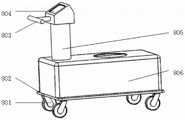
所述底座下侧设有脚轮、上侧设有支撑柱,且所述支撑柱上设有推手和显示屏。The lower side of the base is provided with casters, the upper side is provided with a support column, and the support column is provided with a push handle and a display screen.
一种根据所述悬挂定位机械臂的控制方法,其特征在于:机械臂处于三维位置拖动控制模式时,将力传感器B检测到的在把手一上施加的拖动力


设机器臂位置运动量为Δs=[Δsx,Δsy,Δsz],若机器人控制周期为Δt,,则:Suppose the position movement amount of the robot arm is Δs=[Δsx , Δsy , Δsz ], if the robot control period is Δt, then:

机械臂的初始位姿为:
若机器人末端位置点从初始位置Tc在拖动控制下经过一个控制周期运动到Te,则经过拖动控制后的位姿矩阵为:If the robot end position point moves from the initial position Tc to Te under drag control through a control cycle, the pose matrix after drag control is:

然后基于逆运动学求解算得出各个关节的运动量并实现拖动控制。Then, based on the inverse kinematics solution, the motion amount of each joint is calculated and the drag control is realized.
一种根据所述悬挂定位机械臂的控制方法,其特征在于:使能按钮关闭,机械臂处于远心运动控制模式,此时机械臂的末端位置点(机械臂与末端操作器连接位置)绕指定点做半径r的球面运动,力传感器A检测把手二获得给定的拖动力:A control method for positioning a robotic arm according to the described suspension, characterized in that: the enabling button is turned off, the robotic arm is in a telecentric motion control mode, and the end position point of the robotic arm (the connection position between the robotic arm and the end operator) wraps around the The specified point does a spherical motion of radius r, and the force sensor A detects the

机械臂的末端位置点通过上述作用力绕指定点做圆弧运动,且圆弧运动的角速度

若机器人控制周期为Δt,则机械臂的末端位置点运动的圆弧角度α大小为:If the control period of the robot is Δt, the arc angle α of the movement of the end position point of the robot arm is:

若机器人末端位置点从初始位置Pc=[xc,yc,zc]T在拖动控制下经过一个控制周期运动到Pe=[xe,ye,ze]T,则


上式(1)中:

设机器臂初始在Pc点时末端位姿矩阵为:When the robot arm is initially at point Pc , the end pose matrix is:

经过拖动控制运动后到达Pe点,此时末端位姿矩阵为:After the drag control movement, the pointPe is reached, and the end pose matrix is:

由Pc到Pe的运动过程等效为


上式(2)中,

使能按钮开启,机械臂切换为单轴运动控制模式,将力传感器A检测把手二获得拖动力FA直接映射为伸缩关节、第二旋转关节(4、第三旋转关节的单轴运动,其映射关系为:The enable button is turned on, the robotic arm is switched to the single-axis motion control mode, and the drag force FA obtained by the force sensor A detected by the

且第四旋转关节通过按钮A、按钮B单独控制的正转与反转。And the forward rotation and reverse rotation of the fourth rotary joint are individually controlled by button A and button B.
本发明的优点与积极效果为:The advantages and positive effects of the present invention are:
1、本发明利用六个模块化的关节构成PRPRRR型机械臂,通过新颖的结构形式达到相同的功能要求,其中按钮、把手与传感器安装在机械臂上特定的位置,通过其相互配合并结合算法解算,实现机械臂的三维位置拖动、远心定位拖动与单轴运动控制,控制精确、操作方便,功能稳定可靠、增强人机交互的安全性且降低设备成本。1. The present invention uses six modular joints to form a PRPRRR-type robotic arm, and achieves the same functional requirements through a novel structural form, in which buttons, handles and sensors are installed at specific positions on the robotic arm, through which they cooperate with each other and combine algorithms The solution realizes the three-dimensional position drag, telecentric positioning drag and single-axis motion control of the robotic arm, with precise control, convenient operation, stable and reliable functions, enhanced human-computer interaction safety and reduced equipment costs.
2、本发明的支撑架整体呈C型且为两侧薄板结构,两侧薄板之间空隙便于折叠过程中将支撑架及末端操作器收拢在第四关节连接件周围,当处于工作状态时,支撑架处于展开状态,而其非工作状态下通过其特殊结构形式处于收拢状态,减少了设备整体的占用空间。相比现有的机构形式,本发明具有工作空间大、结构简单、安装拆卸方便、不存在空间奇异点等优点。2. The support frame of the present invention is C-shaped as a whole and has a thin plate structure on both sides. The gap between the two thin plates is convenient for the support frame and the end operator to be gathered around the fourth joint connection during the folding process. When in the working state, The support frame is in an unfolded state, and in a non-working state, it is in a retracted state through its special structural form, which reduces the overall occupied space of the equipment. Compared with the existing mechanism form, the present invention has the advantages of large working space, simple structure, convenient installation and disassembly, and no spatial singularity.
附图说明Description of drawings
图1为本发明的立体示意图一,Fig. 1 is the three-dimensional schematic diagram one of the present invention,
图2为本发明的立体示意图二,Fig. 2 is the three-dimensional schematic diagram two of the present invention,
图3为图1中底盘的结构示意图,Fig. 3 is the structural schematic diagram of the chassis in Fig. 1,
图4为图2中的A-A剖视图,Fig. 4 is A-A sectional view in Fig. 2,
图5为图4中的I处放大图,Fig. 5 is the enlarged view of I in Fig. 4,
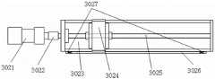
图6为图1中伸缩关节及第二旋转关节的结构示意图,FIG. 6 is a schematic structural diagram of the telescopic joint and the second rotating joint in FIG. 1 ,
图7为图6中伸缩机构的结构示意图,FIG. 7 is a schematic structural diagram of the telescopic mechanism in FIG. 6 ,
图8为图1中第三旋转关节、第四旋转关节及末端操作器的结构示意图,FIG. 8 is a schematic structural diagram of the third rotary joint, the fourth rotary joint and the end effector in FIG. 1 ,
图9为图8中第三旋转关节的结构示意图,Fig. 9 is the structural representation of the third rotating joint in Fig. 8,
图10为图9中第三旋转关节的主视图FIG. 10 is a front view of the third rotary joint in FIG. 9
图11为图10中的B-B剖视图,Fig. 11 is the B-B sectional view in Fig. 10,
图12为图8中第三旋转关节、第四旋转关节及末端操作器的爆炸示意图,Figure 12 is an exploded schematic diagram of the third rotary joint, the fourth rotary joint and the end effector in Figure 8,
图13为图8中支撑架的结构示意图,Fig. 13 is the structural schematic diagram of the support frame in Fig. 8,
图14为本发明算法中需要的各个关节坐标系及其运动形式图,14 is a diagram of each joint coordinate system and its motion form required in the algorithm of the present invention,
图15为本发明的机器人运动坐标系示意图,Fig. 15 is the schematic diagram of the motion coordinate system of the robot of the present invention,
图16为本发明的远心定位运动球坐标系示意图。FIG. 16 is a schematic diagram of the telecentric positioning motion ball coordinate system of the present invention.
其中,1为升降关节,101为电动推缸,102为第一关节支撑件,103为第一关节外壳;2为第一旋转关节,201为第二关节外壳,202为第二关节电机,203为第二关节电机连接件,204为齿轮一,205为第二关节电机安装板,206为交叉滚子轴环,207为第二关节连接件,208为齿轮二;3为伸缩关节,301为第三关节支撑板,302为伸缩机构,3021为电机模组,3022为联轴器,3023为安装座,3024为滑块,3025为丝杠,3026为限位开关安装板,3027为限位开关,303为第三关节连接件,304为第三关节外壳;4为第二旋转关节,401为端关节,402为第四关节连接件;5为第三旋转关节,501为支撑架,502为力传感器B,503为把手一,504为使能按钮,505为按钮A,506为按钮B,507为力传感器A,508为把手二,509为第五关节电机,510为第五关节交叉滚子轴环,511为第二关节轴,512为挡圈;6为第四旋转关节,601为第六关节连接板,602为第六关节交叉滚子轴环,603为第六关节电机转接轴,604为第六关节电机,605为末端固定盘;7为末端操作器;8为底座,801为脚轮,802为底座称重板,803为推手,804为显示屏,805为支撑柱,806为座体。Among them, 1 is the lifting joint, 101 is the electric push cylinder, 102 is the first joint support, 103 is the first joint shell; 2 is the first rotating joint, 201 is the second joint shell, 202 is the second joint motor, 203 204 is the second joint motor connecting piece, 204 is the gear one, 205 is the second joint motor mounting plate, 206 is the cross roller collar, 207 is the second joint connecting piece, 208 is the second gear; 3 is the telescopic joint, 301 is the The third joint support plate, 302 is the telescopic mechanism, 3021 is the motor module, 3022 is the coupling, 3023 is the mounting seat, 3024 is the slider, 3025 is the lead screw, 3026 is the limit switch mounting plate, and 3027 is the limit Switch, 303 is the third joint connecting piece, 304 is the third joint shell; 4 is the second rotating joint, 401 is the end joint, 402 is the fourth joint connecting piece; 5 is the third rotating joint, 501 is the support frame, 502 is force sensor B, 503 is handle one, 504 is enable button, 505 is button A, 506 is button B, 507 is force sensor A, 508 is handle two, 509 is fifth joint motor, 510 is fifth joint cross Roller collar, 511 is the second joint shaft, 512 is the retaining ring; 6 is the fourth rotary joint, 601 is the sixth joint connecting plate, 602 is the sixth joint cross roller collar, 603 is the sixth joint motor rotation 604 is the sixth joint motor, 605 is the end fixing plate; 7 is the end operator; 8 is the base, 801 is the caster, 802 is the base weighing plate, 803 is the push handle, 804 is the display screen, and 805 is the support column , 806 is the seat body.
具体实施方式Detailed ways
下面结合附图对本发明作进一步详述。The present invention will be described in further detail below in conjunction with the accompanying drawings.
如图1~16所示,本发明包括升降关节1、第一旋转关节2、伸缩关节3、第二旋转关节4、第三旋转关节5、第四旋转关节6、末端操作器7以及底座8,升降关节1安装在底座8上且输出端与第一旋转关节2连接,所述第一旋转关节2通过所述升降关节1驱动升降,第一旋转关节2的输出端与伸缩关节3连接,所述伸缩关节3通过所述第一旋转关节2驱动转动,伸缩关节3的输出端与第二旋转关节4连接,所述第二旋转关节4通过所述伸缩关节3伸缩驱动移动,第二旋转关节4的输出端与第三旋转关节5连接,所述第三旋转关节5通过所述第二旋转关节4驱动转动,第三旋转关节5包括支撑架501和驱动单元,且所述支撑架501通过所述驱动单元驱动转动,第四旋转关节6和末端操作器7均安装于所述支撑架501上,且末端操作器7通过第四旋转关节6驱动转动。所述升降关节1、第一旋转关节2、伸缩关节3、第二旋转关节4、第三旋转关节5和第四旋转关节6依次串联形成六自由度机械臂,并通过第四旋转关节6输出端连接末端操作器7,将所有关节的合成运动传递给末端操作器7,并通过运动学分析与控制算法相结合,实现末端操作器7端点的远心运动。As shown in FIGS. 1 to 16 , the present invention includes a lifting joint 1 , a first
如图3所示,所述底座8包括座体806、脚轮801和支撑柱805,升降关节1垂直安装于所述座体806上,所述座体806下侧设有底座承重板802,四个脚轮801分别固定于所述底座承重板802的四个角端,支撑柱805设于座体806上侧,在所述支撑柱805顶端设有推手803和显示屏804,使用者通过手扶推手803,利用四个脚轮801的滚动特性,可将设备整体进行空间位置的移动,方便搬运与使用,为使用者节约时间和节省体力。As shown in FIG. 3 , the
如图4所示,所述升降关节1包括电动推缸101和呈柱状的第一关节支撑件102,其中电动推缸101的底端安装在所述座体806下侧的底座承重板802上,电动推缸101的输出端与第一关节支撑件102的一端相连,所述第一关节支撑件102通过所述电动推缸101驱动升降,且第一旋转关节2安装于所述第一关节支撑件102上,另外如图5所示,所述底座8上侧设有第一关节外壳103将电动推缸101包裹,所述第一关节外壳103上端与一个第二关节外壳201相连,且所述第二关节外壳201将所述第一关节支撑件102包裹,所述第一关节外壳103和第二关节外壳201横截面可以为方形或圆形。As shown in FIG. 4 , the lift joint 1 includes an
如图4~5所示,所述第一旋转关节2包括第二关节电机202、齿轮一204、齿轮二208、交叉滚子轴环206和第二关节连接件207,其中齿轮一204安装于第二关节电机202的输出端,齿轮二208与齿轮一204啮合,且如图5所示,齿轮二208与交叉滚子轴环206内圈一侧同轴连接,交叉滚子轴环206内圈的另一侧与第二关节连接件207同轴连接,伸缩关节3固装于所述第二关节连接件207上。机构工作时,第二关节电机202驱动齿轮一204转动,齿轮一204带动齿轮二208转动,齿轮二208通过交叉滚子轴环206驱动第二关节连接件207转动,进而驱动伸缩关节3转动。所述交叉滚子轴环206为本领域公知技术且为市购产品。As shown in FIGS. 4 to 5 , the first
如图4~5所示,所述第一关节支撑件102上端固设有第二关节电机安装板205,第二关节电机202设于第一关节支撑件102上端内的一侧且与所述第二关节电机安装板205固连,并且所述第二关节电机202的输出轴通过一个第二关节电机连接件203与齿轮一204相连,齿轮二208可转动地设于所述第二关节电机安装板205中部,并通过所述交叉滚子轴环206与第二关节连接件207连接。As shown in FIGS. 4 to 5 , a second joint
如图6~7所示,所述伸缩关节3包括第三关节支撑板301、伸缩机构302和呈板状的第三关节连接件303,其中第三关节支撑板301中部与所述第二关节连接件207连接,伸缩机构302安装于第三关节支撑板301上,所述伸缩机构302设有可移动的滑块3024,且所述第三关节连接件303与所述滑块3024固连,第二旋转关节4安装于所述第三关节连接件303端部。As shown in FIGS. 6 to 7 , the telescopic joint 3 includes a third
如图7所示,所述伸缩机构302包括电机模组3021、安装座3023、滑块3024和丝杠3025,其中安装座3023固装于所述第三关节支撑板301上,电机模组3021和丝杠3025均设于所述安装座3023上,且所述丝杠3025通过电机模组3021驱动转动,滑块3024与所述安装座3023滑动连接,在所述安装座3023上设有与所述滑块3024配合的滑轨,所述滑块3024内部设有丝母套装于所述丝杠3025上。机构工作时,电机模组3021驱动丝杠3025转动,丝杠3025驱动滑块3024移动,进而带动所述第三关节连接件303直线移动。As shown in FIG. 7 , the
如图7所示,所述电机模组3021的输出轴通过一个联轴器3022与所述丝杠3025的一端连接,所述安装座3023两侧设有与所述滑块3024配合的滑轨,中间设有所述丝杠3025,所述安装座3023一侧设有限位开关安装板3026,且所述限位开关安装板3026两端分别设有限位开关3027用于实现滑块3024的零位寻找以及电气限位,所述限位开关3027为本领域公知技术且为市购产品。As shown in FIG. 7 , the output shaft of the
如图6所示,所述第三关节支撑板301上设有第三关节外壳304将所述伸缩结构302包裹。As shown in FIG. 6 , the third
如图6和图8所示,所述第二旋转关节4包括端关节401和呈柱状的第四关节连接件402,其中端关节401固装于所述第三关节连接件303端部,所述端关节401内设有第四关节电机,且所述第四关节连接件402一端通过所述第四关节电机驱动转动,另一端与所述第三旋转关节5固连。As shown in FIG. 6 and FIG. 8 , the second
如图8~13所示,所述第三旋转关节5包括支撑架501和驱动单元,其中所述驱动单元包括第五关节电机509、第五关节轴511和第五关节交叉滚子轴环510,其中如图11所示,所述第四关节连接件402端部插入所述支撑架501中部,且所述第四关节连接件402端部一侧设有第五关节电机509,另一侧设有第五关节轴511,且第五关节电机509和第五关节轴511同轴设置,其中第五关节电机509固设于第四关节连接件402上且输出端与支撑架501中部位置的一侧连接,第五关节轴511一端通过第五关节交叉滚子轴环510安装于第四关节连接件402上,第五关节轴511另一端与支撑架501中部位置的另一侧连接并通过挡圈512限位固定。机构工作时,所述第五关节电机509驱动所述支撑架501转动。所述第五关节交叉滚子轴环510为本领域公知技术且为市购产品。As shown in FIGS. 8-13 , the third
如图13所示,所述支撑架501整体呈C型且为两侧薄板结构,两侧薄板之间空隙便于折叠过程中将支撑架501及末端操作器7收拢在第四关节连接件402周围,并且所述两侧薄板上端和下端分别对应汇聚到一起,可用于固定末端操作器7。如图1~2所示,当处于工作状态时,支撑架501处于展开状态,而其非工作状态下通过其特殊结构形式处于收拢状态,减少了设备整体的占用空间。As shown in FIG. 13 , the
如图8~9和图12所示,所述支撑架501中部与第五关节电机509同轴位置的A处设有力传感器B502和把手一503,所述支撑架501与第四旋转关节6连接一端的B处位置设有力传感器A507和把手二508,所述力传感器B502和力传感器A507均为多维力传感器,此为本领域公知技术且为市购产品。另外如图9和图12所示,所述支撑架501与第四旋转关节6连接一端还设有使能按钮504、按钮A505和按钮B506。As shown in FIGS. 8-9 and 12 , a force sensor B502 and a
本发明包括拖动模式与单轴运动模式两种工作状态,其中拖动模式还包括远心定位拖动与三维位置拖动两种工作状态,如图14所示,机械臂的远心定位拖动方案主要是通过力传感器A507检测把手二508上的拖动力变化情况,例如检测到拖动力沿着图中俯仰方向时,通过控制算法求解出各个运动关节转动量实现该方向的远心拖动功能,其余方向的拖动实现方式与此相同,进而实现远心运动(俯仰、偏转、远心移动)所需要的三个方向的拖动功能。而三维位置拖动主要是通过力传感器B502检测把手一503上拖动力的变化情况,当检测到把手一503的拖动力沿着XO-YO-ZO中的一个时,通过控制算法求解出升降关节1、第一旋转关节2、伸缩关节3的转动量,进而实现末端操作器7的三维位置拖动,在此过程中末端操作器7相对于把手一503不运动,从而实现末端操作器7在三维空间中的位置拖动定位。The present invention includes two working states: dragging mode and single-axis motion mode, wherein the dragging mode also includes two working states: telecentric positioning dragging and three-dimensional position dragging. As shown in Figure 14, the telecentric positioning dragging of the robotic arm The motion scheme is mainly to detect the change of the drag force on the
另外本发明还可以通过力传感器A507检测把手二508实现单轴运动功能,其实现过程通过按下使能按钮504,然后通过力传感器A507(其为多维力传感器)检测把手二508上拖动力的变化,实现第二旋转关节4、第三旋转关节5和第四旋转关节6的单轴运动。另外由于远心定位拖动与单轴运动均使用了把手二508与力传感器A507,所以本发明通过按钮A505和按钮B506单独控制第四旋转关节6的正转与反转,第四旋转关节6通过两个按钮实现单轴运动,主要为了实现在远心运动过程中,末端操作器7仍然具有自转的功能。所述使能按钮504、按钮A505和按钮B506的具体控制原理为本领域公知技术。In addition, the present invention can also use the force sensor A507 to detect the
在力拖动方案与单轴运动过程中,使用者还可以通过拖拽把手一503和把手二508,实现其运动功能,更方便且更有效。During the force-drag scheme and the single-axis motion, the user can also drag the handle one 503 and the handle two 508 to realize its motion function, which is more convenient and effective.
如图12所示,所述第四旋转关节6包括第六关节电机604和第六关节连接板601,第六关节电机604固定在支撑架501上,第六关节连接板601通过第六关节电机604驱动转动,且第六关节连接板601与末端操作器7连接。As shown in FIG. 12 , the fourth rotating joint 6 includes a sixth
如图12所示,所述第四旋转关节6还包括第六关节交叉滚子轴环602、第六关节电机转接轴603和末端固定盘605,其中末端固定盘605和第六关节电机604都固定在支撑架501上,且第六关节电机604输出轴与所述第六关节电机转接轴603连接,所述第六关节电机转接轴603与第六关节交叉滚子轴环602一侧内圈连接,第六关节交叉滚子轴环602另一侧内圈与第六关节连接板601连接,而第六关节交叉滚子轴环602外圈固定在末端固定盘605上。所述第六关节交叉滚子轴环602为本领域公知技术且为市购产品。As shown in FIG. 12 , the fourth rotary joint 6 further includes a sixth joint crossed roller collar 602 , a sixth joint
本发明机械臂整体的走线形式采用内部走线,电源线与信号线通过中空关节及内部走线孔连接到底座部分,再与外部电源连接,减少机械臂运动过程中线缆的缠绕问题,同时也增强美观性。The overall routing form of the mechanical arm of the present invention adopts internal routing, the power cable and the signal cable are connected to the base part through the hollow joint and the internal routing hole, and then connected to the external power supply, so as to reduce the problem of cable winding during the movement of the mechanical arm. It also enhances aesthetics.
本发明的工作原理为:The working principle of the present invention is:
本发明工作时,第一旋转关节2通过所述升降关节1驱动升降,伸缩关节3通过所述第一旋转关节2驱动转动,第二旋转关节4通过所述伸缩关节3伸缩驱动移动,第三旋转关节5通过所述第二旋转关节4驱动转动,第三旋转关节5包括支撑架501和驱动单元,且所述支撑架501通过所述驱动单元驱动转动,第四旋转关节6和末端操作器7均安装于所述支撑架501上,且末端操作器7通过第四旋转关节驱动转动。所述升降关节1、第一旋转关节2、伸缩关节3、第二旋转关节4、第三旋转关节5和第四旋转关节6依次串联形成六自由度机械臂,并通过第四旋转关节6输出端连接末端操作器7,将所有关节的合成运动传递给末端操作器7,并通过运动学分析与控制算法相结合,实现末端操作器7端点的远心运动。When the present invention works, the first
另外本发明控制方法如下:In addition, the control method of the present invention is as follows:
一、关于机器人正运动学及逆运动学控制方法,本发明对于机械臂的运动控制可以建立如图15所示的机器人运动坐标系,建立机器人D-H参数表如下:1. Regarding the control method of forward kinematics and inverse kinematics of the robot, the present invention can establish the motion coordinate system of the robot as shown in Figure 15 for the motion control of the manipulator, and establish the D-H parameter table of the robot as follows:
机器人D-H参数表Robot D-H parameter table
采用机器人常规D-H参数法即可得到机器人的正运动学表达式。The positive kinematics expression of the robot can be obtained by using the conventional D-H parameter method of the robot.
基于正运动学的表达式,当我们给定一个机器人的末端位姿阵:Based on the expression of positive kinematics, when we give a robot's end pose matrix:

可以求解机器人的各个关节运动量为:The motion of each joint of the robot can be solved as:
θ5=arccos(-t33)=π-arccos(t33);θ5 =arccos(-t33 )=π-arccos(t33 );

d1=t34-a0+a4+a5*cθ5+a6*sθ5;d1 =t34 -a0 +a4 +a5 *cθ5 +a6 *sθ5 ;


θ4=θ2-arctan(t23/t13)。θ4 =θ2 −arctan(t23 /t13 ).
上述求解过程为常规数学运算,可通过现有的数学控制软件实现。The above solving process is a conventional mathematical operation, which can be realized by existing mathematical control software.
二、关于机器人位置运动控制方法,在位置控制模式下,末端操作器7在三维空间进行位置拖动定位,此时末端操作器7相对于把手一503不运动,从而可通过把手一503实现末端操作器7在三维空间中的位置拖动定位。2. Regarding the robot position motion control method, in the position control mode, the
将力传感器B502上检测到的在把手一503上施加的拖动力


上式为本领域公知技术,可参见机器人学或其他相关文献。The above formula is a well-known technology in the art, and reference may be made to robotics or other related documents.
设机器臂位置运动量为Δs=[Δsx,Δsy,Δsz],若机器人控制周期为Δt,,则:Suppose the position movement amount of the robot arm is Δs=[Δsx , Δsy , Δsz ], if the robot control period is Δt, then:

机械臂的初始位姿为,
若机器人末端位置点从初始位置Tc在拖动控制下经过一个控制周期运动到Te,则经过拖动控制后的位姿矩阵为:If the robot end position point moves from the initial position Tc to Te under drag control through a control cycle, the pose matrix after drag control is:

基于逆运动学求解算法可以得出各个关节的运动量,进而实现对机器人的位置拖动控制。Based on the inverse kinematics solution algorithm, the motion amount of each joint can be obtained, and then the position drag control of the robot can be realized.
上述过程可通过现有的数学控制软件实现。The above process can be realized by existing mathematical control software.
三、关于本发明机器人远心运动控制方法,在远心运动控制模式下,也即使能按钮504关闭,如图16所示,末端操作器7将绕指定点进行远心运动,机械臂的末端位置点(即机械臂与末端操作器7连接位置)将绕指定点做半径r的球面运动,其中r为机械臂末端位置点到指定远心点的距离,θ决定了在球面上的具体位置。3. Regarding the robot telecentric motion control method of the present invention, in the telecentric motion control mode, even if the enable
力传感器A507检测把手二508获得给定的拖动力:Force sensor A507 detects handle two 508 to obtain a given drag force:

需要控制末端操作器7将沿作用力方向上绕指定点做圆弧运动,圆弧半径为r,圆弧运动的角速度

若机器人控制周期为Δt,则需要运动的圆弧角度α大小为:If the control cycle of the robot is Δt, the arc angle α that needs to be moved is:

如图16所示,若机器人末端位置点从初始位置Pc=[xc,yc,zc]T在拖动控制下经过一个控制周期运动到Pe=[xe,ye,ze]T,则根据前面分析可知,


上式(1)中:

设机器人初始在Pc点时末端位姿矩阵为:When the robot is initially at point Pc , the end pose matrix is:

经过拖动控制运动后到达Pe点,此时末端位姿矩阵为:After the drag control movement, the pointPe is reached, and the end pose matrix is:

由Pc到Pe的运动过程可以等效为


上式(2)中,

通过式(1)和(2)最终可以得到远心拖动控制时机器人需要运动控制的目标位姿矩阵Te,再通过机器人逆运动学即可实现远心拖动控制。Through equations (1) and (2), the target pose matrix Te that the robot needs to motion control in the telecentric drag control can be finally obtained, and then the telecentric drag control can be realized through the inverse kinematics of the robot.
上述过程可通过现有的数学控制软件实现。The above process can be realized by existing mathematical control software.
四、使能按钮504按下开启,上述远心拖动控制模式切换为单轴运动控制模式。4. Press the
在此模式下,将力传感器A507检测把手二508获得拖动力FA直接映射为伸缩关节3、第二旋转关节4和第三旋转关节5的单轴运动:In this mode, the drag force FA obtained by the force sensorA507 detected by the

上式为本领域公知技术,可参加机器人学等相关文献获得。The above formula is a well-known technology in the art, and can be obtained from related literatures such as robotics.
在此模式下,本发明可通过按钮A505、按钮B506单独控制第四旋转关节6的正转与反转,实现机器人的单轴运动控制。In this mode, the present invention can independently control the forward rotation and reverse rotation of the fourth rotary joint 6 through the button A505 and the button B506, so as to realize the single-axis motion control of the robot.
上述过程可通过现有的数学控制软件实现。The above process can be realized by existing mathematical control software.
Claims (9)


Priority Applications (1)
| Application Number | Priority Date | Filing Date | Title |
|---|---|---|---|
| CN202010106557.9ACN113288427B (en) | 2020-02-21 | 2020-02-21 | A suspension positioning manipulator and its control method |
Applications Claiming Priority (1)
| Application Number | Priority Date | Filing Date | Title |
|---|---|---|---|
| CN202010106557.9ACN113288427B (en) | 2020-02-21 | 2020-02-21 | A suspension positioning manipulator and its control method |
Publications (2)
| Publication Number | Publication Date |
|---|---|
| CN113288427A CN113288427A (en) | 2021-08-24 |
| CN113288427Btrue CN113288427B (en) | 2022-07-05 |
Family
ID=77317413
Family Applications (1)
| Application Number | Title | Priority Date | Filing Date |
|---|---|---|---|
| CN202010106557.9AActiveCN113288427B (en) | 2020-02-21 | 2020-02-21 | A suspension positioning manipulator and its control method |
Country Status (1)
| Country | Link |
|---|---|
| CN (1) | CN113288427B (en) |
Families Citing this family (5)
| Publication number | Priority date | Publication date | Assignee | Title |
|---|---|---|---|---|
| CN113910288A (en)* | 2021-10-20 | 2022-01-11 | 珞石(北京)科技有限公司 | Compact collaborative robotic arm wrist with integrated drag-enable handle |
| CN114177481B (en)* | 2021-11-16 | 2023-10-13 | 山东科技大学 | Catheter traction robot for vascular intervention operation |
| CN114886562A (en)* | 2022-04-07 | 2022-08-12 | 吉林省金博弘智能科技有限责任公司 | Robot for single-hole pleuroperitoneal cavity minimally invasive surgery |
| CN115634043A (en)* | 2022-10-17 | 2023-01-24 | 上海微创医疗机器人(集团)股份有限公司 | Operation console |
| CN118000913B (en)* | 2024-03-13 | 2025-07-11 | 山东威高手术机器人有限公司 | Suspension mechanism, surgical robot, and retraction method and extension method thereof |
Citations (4)
| Publication number | Priority date | Publication date | Assignee | Title |
|---|---|---|---|---|
| CN107041786A (en)* | 2017-05-25 | 2017-08-15 | 杭州妙手机器人有限公司 | A kind of laparoscopic device |
| CN207979965U (en)* | 2017-06-21 | 2018-10-19 | 上海寰晟新能源科技有限公司 | Upper limb rehabilitation robot and its system |
| CN109775345A (en)* | 2018-12-09 | 2019-05-21 | 西安航天精密机电研究所 | A kind of bullet carrying pick-and-place specialized robot |
| CN110251197A (en)* | 2019-07-05 | 2019-09-20 | 四川大学 | An auxiliary device for spinal drilling surgery |
Family Cites Families (13)
| Publication number | Priority date | Publication date | Assignee | Title |
|---|---|---|---|---|
| KR100695468B1 (en)* | 2005-10-07 | 2007-03-16 | 한양대학교 산학협력단 | Multiple degree of freedom robot for positioning surgical instruments |
| EP1915963A1 (en)* | 2006-10-25 | 2008-04-30 | The European Atomic Energy Community (EURATOM), represented by the European Commission | Force estimation for a minimally invasive robotic surgery system |
| JP5146621B2 (en)* | 2011-01-31 | 2013-02-20 | トヨタ自動車株式会社 | Articulated arm robot, control method and control program |
| CN102764157B (en)* | 2012-04-13 | 2014-12-10 | 中国科学院深圳先进技术研究院 | Robot for orthopaedic surgery |
| WO2016025544A1 (en)* | 2014-08-15 | 2016-02-18 | Intuitive Surgical Operations, Inc. | A surgical system with variable entry guide configurations |
| CN105686883B (en)* | 2016-03-14 | 2018-11-30 | 昆山一邦泰汽车零部件制造有限公司 | A kind of redundant degree of freedom holds mirror mechanical arm |
| CN109091237B (en)* | 2017-06-21 | 2020-08-04 | 山东威高手术机器人有限公司 | Minimally invasive surgical instrument auxiliary system |
| CN107184275B (en)* | 2017-07-25 | 2018-09-14 | 吉林大学 | A kind of robot for assisting splanchnocoel Minimally Invasive Surgery |
| CN108338840A (en)* | 2018-04-17 | 2018-07-31 | 成都博恩思医学机器人有限公司 | A kind of laparoscopic surgery holds robot system with endoscope |
| EP3781064A4 (en)* | 2018-04-20 | 2022-01-26 | Covidien LP | Surgical port manipulator |
| CN108742797A (en)* | 2018-07-10 | 2018-11-06 | 哈尔滨理工大学 | A kind of passive hybrid subclavian vein puncture robot of master |
| CN109079771B (en)* | 2018-10-29 | 2024-05-03 | 深圳众为兴技术股份有限公司 | Five-joint robot and control method thereof |
| CN109431625A (en)* | 2018-11-16 | 2019-03-08 | 镇江市新天医疗器械有限公司 | A kind of swing arm adjustment structure of surgical operation microscope |
- 2020
- 2020-02-21CNCN202010106557.9Apatent/CN113288427B/enactiveActive
Patent Citations (4)
| Publication number | Priority date | Publication date | Assignee | Title |
|---|---|---|---|---|
| CN107041786A (en)* | 2017-05-25 | 2017-08-15 | 杭州妙手机器人有限公司 | A kind of laparoscopic device |
| CN207979965U (en)* | 2017-06-21 | 2018-10-19 | 上海寰晟新能源科技有限公司 | Upper limb rehabilitation robot and its system |
| CN109775345A (en)* | 2018-12-09 | 2019-05-21 | 西安航天精密机电研究所 | A kind of bullet carrying pick-and-place specialized robot |
| CN110251197A (en)* | 2019-07-05 | 2019-09-20 | 四川大学 | An auxiliary device for spinal drilling surgery |
Also Published As
| Publication number | Publication date |
|---|---|
| CN113288427A (en) | 2021-08-24 |
Similar Documents
| Publication | Publication Date | Title |
|---|---|---|
| CN113288427B (en) | A suspension positioning manipulator and its control method | |
| JP6255724B2 (en) | Robot and robot operation method | |
| CN101773400B (en) | Minimally invasive surgical robot master control data gloves | |
| US20180264641A1 (en) | Mobile manipulation device | |
| CN106037937B (en) | A kind of operating robot motion arm with adaptive ability | |
| CN104908042B (en) | Extensible-connection six-freedom-degree force feedback mechanical arm | |
| CN105116961B (en) | Intelligent force feedback handle and control method thereof | |
| CN102152299B (en) | (6 plus 1)-dimension force feedback sensing device | |
| US11890069B2 (en) | Sensors for touch-free control of surgical robotic systems | |
| US10953547B2 (en) | Control apparatus, robot, and robot system | |
| CN104622585B (en) | A kind of peritoneoscope micro-wound operation robot principal and subordinate's isomorphism main hands of formula remote operating | |
| JP7360778B2 (en) | Dual plane robotic arm device suitable for vascular intervention surgery | |
| CN105397838B (en) | Main hand operating wrist of master-slave robot | |
| CN103624790B (en) | Control method of teleoperation of six-freedom-degree mechanical arm | |
| CN114027988B (en) | A main manipulator of a three-degree-of-freedom continuum robot and its working method | |
| CN207745191U (en) | A kind of novel operation robot main manipulator | |
| CN101817181A (en) | Six-degree-of-freedom flexible mechanical arm based on pneumatic muscles | |
| CN107838932A (en) | A kind of robot of accompanying and attending to multi-degree-of-freemechanical mechanical arm | |
| CN101829999A (en) | Reachable domain detection device for astronaut spatial activities | |
| CN205885526U (en) | Nimble operation shoulder joint | |
| CN1206082C (en) | Hand controller of six freedom universal isomeric robot | |
| CN207745190U (en) | A kind of novel operation robot main manipulator | |
| CN114748170A (en) | Main manipulator for endoscope type minimally invasive surgery robot | |
| Li et al. | Design and optimization of a haptic manipulator using series-parallel mechanism | |
| CN110722573B (en) | Assisted motion robotic arm and nursing bed |
Legal Events
| Date | Code | Title | Description |
|---|---|---|---|
| PB01 | Publication | ||
| PB01 | Publication | ||
| SE01 | Entry into force of request for substantive examination | ||
| SE01 | Entry into force of request for substantive examination | ||
| GR01 | Patent grant | ||
| GR01 | Patent grant |