CN113258564B - Group string type photovoltaic cluster inverter grid-connected resonance suppression method based on hybrid damping - Google Patents
Group string type photovoltaic cluster inverter grid-connected resonance suppression method based on hybrid dampingDownload PDFInfo
- Publication number
- CN113258564B CN113258564BCN202110501964.4ACN202110501964ACN113258564BCN 113258564 BCN113258564 BCN 113258564BCN 202110501964 ACN202110501964 ACN 202110501964ACN 113258564 BCN113258564 BCN 113258564B
- Authority
- CN
- China
- Prior art keywords
- grid
- resonance
- inverter
- resonance suppression
- suppression circuit
- Prior art date
- Legal status (The legal status is an assumption and is not a legal conclusion. Google has not performed a legal analysis and makes no representation as to the accuracy of the status listed.)
- Active
Links
Images


Classifications
- H—ELECTRICITY
- H02—GENERATION; CONVERSION OR DISTRIBUTION OF ELECTRIC POWER
- H02J—CIRCUIT ARRANGEMENTS OR SYSTEMS FOR SUPPLYING OR DISTRIBUTING ELECTRIC POWER; SYSTEMS FOR STORING ELECTRIC ENERGY
- H02J3/00—Circuit arrangements for AC mains or AC distribution networks
- H02J3/002—Flicker reduction, e.g. compensation of flicker introduced by non-linear load
- H—ELECTRICITY
- H02—GENERATION; CONVERSION OR DISTRIBUTION OF ELECTRIC POWER
- H02J—CIRCUIT ARRANGEMENTS OR SYSTEMS FOR SUPPLYING OR DISTRIBUTING ELECTRIC POWER; SYSTEMS FOR STORING ELECTRIC ENERGY
- H02J3/00—Circuit arrangements for AC mains or AC distribution networks
- H02J3/01—Arrangements for reducing harmonics or ripples
- H—ELECTRICITY
- H02—GENERATION; CONVERSION OR DISTRIBUTION OF ELECTRIC POWER
- H02J—CIRCUIT ARRANGEMENTS OR SYSTEMS FOR SUPPLYING OR DISTRIBUTING ELECTRIC POWER; SYSTEMS FOR STORING ELECTRIC ENERGY
- H02J3/00—Circuit arrangements for AC mains or AC distribution networks
- H02J3/38—Arrangements for parallely feeding a single network by two or more generators, converters or transformers
- H02J3/381—Dispersed generators
- H—ELECTRICITY
- H02—GENERATION; CONVERSION OR DISTRIBUTION OF ELECTRIC POWER
- H02M—APPARATUS FOR CONVERSION BETWEEN AC AND AC, BETWEEN AC AND DC, OR BETWEEN DC AND DC, AND FOR USE WITH MAINS OR SIMILAR POWER SUPPLY SYSTEMS; CONVERSION OF DC OR AC INPUT POWER INTO SURGE OUTPUT POWER; CONTROL OR REGULATION THEREOF
- H02M1/00—Details of apparatus for conversion
- H02M1/12—Arrangements for reducing harmonics from AC input or output
- H02M1/126—Arrangements for reducing harmonics from AC input or output using passive filters
- H—ELECTRICITY
- H02—GENERATION; CONVERSION OR DISTRIBUTION OF ELECTRIC POWER
- H02M—APPARATUS FOR CONVERSION BETWEEN AC AND AC, BETWEEN AC AND DC, OR BETWEEN DC AND DC, AND FOR USE WITH MAINS OR SIMILAR POWER SUPPLY SYSTEMS; CONVERSION OF DC OR AC INPUT POWER INTO SURGE OUTPUT POWER; CONTROL OR REGULATION THEREOF
- H02M7/00—Conversion of AC power input into DC power output; Conversion of DC power input into AC power output
- H02M7/42—Conversion of DC power input into AC power output without possibility of reversal
- H02M7/44—Conversion of DC power input into AC power output without possibility of reversal by static converters
- H02M7/48—Conversion of DC power input into AC power output without possibility of reversal by static converters using discharge tubes with control electrode or semiconductor devices with control electrode
- H02M7/493—Conversion of DC power input into AC power output without possibility of reversal by static converters using discharge tubes with control electrode or semiconductor devices with control electrode the static converters being arranged for operation in parallel
- H—ELECTRICITY
- H02—GENERATION; CONVERSION OR DISTRIBUTION OF ELECTRIC POWER
- H02J—CIRCUIT ARRANGEMENTS OR SYSTEMS FOR SUPPLYING OR DISTRIBUTING ELECTRIC POWER; SYSTEMS FOR STORING ELECTRIC ENERGY
- H02J2203/00—Indexing scheme relating to details of circuit arrangements for AC mains or AC distribution networks
- H02J2203/10—Power transmission or distribution systems management focussing at grid-level, e.g. load flow analysis, node profile computation, meshed network optimisation, active network management or spinning reserve management
- H—ELECTRICITY
- H02—GENERATION; CONVERSION OR DISTRIBUTION OF ELECTRIC POWER
- H02J—CIRCUIT ARRANGEMENTS OR SYSTEMS FOR SUPPLYING OR DISTRIBUTING ELECTRIC POWER; SYSTEMS FOR STORING ELECTRIC ENERGY
- H02J2203/00—Indexing scheme relating to details of circuit arrangements for AC mains or AC distribution networks
- H02J2203/20—Simulating, e g planning, reliability check, modelling or computer assisted design [CAD]
- H—ELECTRICITY
- H02—GENERATION; CONVERSION OR DISTRIBUTION OF ELECTRIC POWER
- H02J—CIRCUIT ARRANGEMENTS OR SYSTEMS FOR SUPPLYING OR DISTRIBUTING ELECTRIC POWER; SYSTEMS FOR STORING ELECTRIC ENERGY
- H02J2300/00—Systems for supplying or distributing electric power characterised by decentralized, dispersed, or local generation
- H02J2300/20—The dispersed energy generation being of renewable origin
- H02J2300/22—The renewable source being solar energy
- H02J2300/24—The renewable source being solar energy of photovoltaic origin
- H02J2300/26—The renewable source being solar energy of photovoltaic origin involving maximum power point tracking control for photovoltaic sources
- Y—GENERAL TAGGING OF NEW TECHNOLOGICAL DEVELOPMENTS; GENERAL TAGGING OF CROSS-SECTIONAL TECHNOLOGIES SPANNING OVER SEVERAL SECTIONS OF THE IPC; TECHNICAL SUBJECTS COVERED BY FORMER USPC CROSS-REFERENCE ART COLLECTIONS [XRACs] AND DIGESTS
- Y02—TECHNOLOGIES OR APPLICATIONS FOR MITIGATION OR ADAPTATION AGAINST CLIMATE CHANGE
- Y02E—REDUCTION OF GREENHOUSE GAS [GHG] EMISSIONS, RELATED TO ENERGY GENERATION, TRANSMISSION OR DISTRIBUTION
- Y02E40/00—Technologies for an efficient electrical power generation, transmission or distribution
- Y02E40/40—Arrangements for reducing harmonics
Landscapes
- Engineering & Computer Science (AREA)
- Power Engineering (AREA)
- Physics & Mathematics (AREA)
- Nonlinear Science (AREA)
- Inverter Devices (AREA)
Abstract
Translated fromChinese
Description
Translated fromChinese技术领域technical field
本发明涉及光伏逆变器并网谐振抑制技术领域,更具体的说是涉及一种基于混合阻尼的组串式光伏集群逆变器并网谐振抑制方法。The invention relates to the technical field of grid-connected resonance suppression of photovoltaic inverters, and more particularly to a method for suppressing grid-connected resonance of photovoltaic inverters based on hybrid damping.
背景技术Background technique
随着光伏发电系统并网容量占原有电力系统容量的比重不断增大,为优化并网逆变器配置,提升最大功率点跟踪效率,提高系统故障冗余运行能力,越来越多光伏发电系统采用组串式光伏集群逆变器并联入网的的方式。然而,多组串式光伏集群逆变器接入电网会引起谐振,对电力系统的稳定运行和电能质量产生不利影响。在国内外现有光伏并网工程中,因逆变器并联运行产生谐振,导致并网失败,甚至损坏电力设备的事故不在少数。As the proportion of the grid-connected capacity of the photovoltaic power generation system to the original power system capacity continues to increase, in order to optimize the configuration of grid-connected inverters, improve the maximum power point tracking efficiency, and improve the system's fault redundancy operation capability, more and more photovoltaic power generation The system adopts the method of string-type photovoltaic cluster inverters and connected to the grid. However, the connection of multi-string photovoltaic cluster inverters to the grid will cause resonance, which will adversely affect the stable operation and power quality of the power system. In the existing photovoltaic grid-connected projects at home and abroad, there are not a few accidents caused by the parallel operation of inverters, resulting in grid-connection failure and even damage to power equipment.
国内外学者针对光伏并网谐振抑制开展了很多研究。提出一种基于有源阻尼的控制策略,在进行谐波补偿时,通过并联有源滤波器抑制系统谐振。2015年第35期的《中国电机工程学报》中《光伏并网逆变器集群的谐振原因及其抑制方法》一文中提出了一种在不改变硬件拓扑结构或增加传感器的情况下抑制逆变器谐波电流的有源谐波电导法,以抑制系统谐振。但其用高斯白噪作为谐波源进行逆变器内部谐振仿真,并未在完整的光伏系统验证方法的可行性。2016年第44期的《电力系统保护与控制》中《基于陷波控制的LCL型光伏并网逆变器谐波谐振抑制研究》一文中提出一种基于有源阻尼的陷波控制策略。该方法虽能有效抑制并联谐振却忽略了电网阻抗对系统稳定性的影响。Scholars at home and abroad have carried out a lot of research on photovoltaic grid-connected resonance suppression. A control strategy based on active damping is proposed. When harmonic compensation is performed, the system resonance is suppressed by parallel active filters. In the article "Resonance Reasons and Suppression Methods of Photovoltaic Grid-connected Inverter Clusters" in the 35th issue of "Chinese Journal of Electrical Engineering" in 2015, a method to suppress the inverter without changing the hardware topology or adding sensors is proposed. Active harmonic conductance method of harmonic current of the device to suppress system resonance. However, it uses Gaussian white noise as a harmonic source to simulate the internal resonance of the inverter, and does not verify the feasibility of the method in a complete photovoltaic system. A notch control strategy based on active damping is proposed in the paper "Research on Harmonic Resonance Suppression of LCL-type Photovoltaic Grid-connected Inverter Based on Notch Control" in the 44th issue of "Power System Protection and Control" in 2016. Although this method can effectively suppress parallel resonance, it ignores the influence of grid impedance on system stability.
上述方法都是在理想电网情况下实现,但在实际中,一些偏远地区或者山区随着并网逆变器的增加会引起系统谐振,使电能质量变差,导致入网电流内产生较严重的谐波,输出电流质量较差。The above methods are all implemented under ideal grid conditions, but in practice, with the increase of grid-connected inverters in some remote areas or mountainous areas, system resonance will be caused, the power quality will be deteriorated, and serious harmonics will be generated in the grid current. wave, the output current quality is poor.
因此,如何抑制光伏发电系统并网谐振同时提高输出电流质量是本领域技术人员亟需解决的问题。Therefore, how to suppress the grid-connected resonance of the photovoltaic power generation system while improving the quality of the output current is an urgent problem to be solved by those skilled in the art.
发明内容SUMMARY OF THE INVENTION
有鉴于此,本发明提供了一种基于混合阻尼的组串式光伏集群逆变器并网谐振抑制方法,通过在逆变器电流环中引入电容电流反馈与并网电压比例前馈作为有源阻尼,以削弱并网电流的谐波,可以有效地抑制LCL逆变器的谐振,有效地提高逆变器控制系统的稳定性。且不需要额外加装硬件设备,可行性强,可代替无源阻尼,有效降低硬件成本。同时,在此基础上加入二阶RLC谐振抑制电路作为无源阻尼,具有基波损耗低、抑制效果好的优点,使集群并网时逆变器输出电流满足并网条件,降低系统成本,提高了系统的鲁棒性。In view of this, the present invention provides a method for suppressing grid-connected resonance of string-type photovoltaic cluster inverters based on hybrid damping, by introducing capacitive current feedback and grid-connected voltage proportional feedforward into the inverter current loop as active Damping to weaken the harmonics of the grid-connected current can effectively suppress the resonance of the LCL inverter and effectively improve the stability of the inverter control system. And no additional hardware equipment is required, which is highly feasible and can replace passive damping, effectively reducing hardware costs. At the same time, a second-order RLC resonance suppression circuit is added on this basis as passive damping, which has the advantages of low fundamental wave loss and good suppression effect, so that the output current of the inverter can meet the grid connection conditions when the cluster is connected to the grid, reducing the system cost and improving the the robustness of the system.
为了实现上述目的,本发明采用如下技术方案:In order to achieve the above object, the present invention adopts the following technical solutions:
一种基于混合阻尼的组串式光伏集群逆变器并网谐振抑制方法,包括:A method for suppressing grid-connected resonance of a string-type photovoltaic cluster inverter based on hybrid damping, comprising:
步骤1:通过并网逆变器的数学模型进行了谐振机理与谐振特性分析,获得光伏发电系统的谐振频率;Step 1: The resonance mechanism and resonance characteristics are analyzed through the mathematical model of the grid-connected inverter, and the resonance frequency of the photovoltaic power generation system is obtained;
光伏发电系统的所述并网逆变器输出电压ui至并网电流ip1的传递函数为:The transfer function of the grid-connected inverter output voltageui of the photovoltaic power generation system to the grid-connected current ip1 is:

式中,In the formula,


其中,ui为第一台逆变器输出电压;ip1为第一台逆变器并网电流;L11为第一台逆变器侧电感值;L21为第一台逆变器网侧电感值;Lg为电网电感值;C1为第一台逆变器滤波电容;GZ1为逆变器侧电感传递函数;GC为逆变器滤波电容传递函数;GZ2为逆变器网侧传递函数;Gg为电网阻抗传递函数;为求得系统的谐振频率,化简式(1),令s=jω,代入式(1)得Among them,ui is the output voltage of the first inverter; ip1 is the grid-connected current of the first inverter;L11 is the inductance value of the first inverter;L21 is the first inverter grid side inductance value; Lg is the grid inductance value; C1 is the first inverter filter capacitor; GZ1 is the inverter side inductance transfer function; GC is the inverter filter capacitor transfer function; GZ2 is the inverter Gg is the power grid impedance transfer function; in order to obtain the resonant frequency of the system, formula (1) is simplified, and s=jω is substituted into formula (1) to obtain

因此所述光伏发电系统的谐振频率为:Therefore, the resonance frequency of the photovoltaic power generation system is:

光伏发电系统有两个谐振峰;fLCLg是光伏发电系统与电网交互的谐振点;fLCL是光伏发电系统内部谐振点;The photovoltaic power generation system has two resonance peaks; fLCLg is the resonance point of the photovoltaic power generation system interacting with the grid; fLCL is the internal resonance point of the photovoltaic power generation system;
步骤2:在所述并网逆变器电流环中引入电容电流反馈与并网电压比例前馈作为有源阻尼,以抑制系统内部谐振;电容电流反馈与并网电压比例前馈的传递函数为:Step 2: Introduce capacitive current feedback and grid-connected voltage proportional feedforward as active damping in the grid-connected inverter current loop to suppress the internal resonance of the system; the transfer function of capacitive current feedback and grid-connected voltage proportional feedforward is: :

其中,
步骤3:在步骤2中在逆变器电流环中引入电容电流反馈与并网电压比例前馈作为有源阻尼的基础上加入二阶RLC谐振抑制电路作为无源阻尼,以抑制系统与电网间谐振;Step 3: In
二阶RLC谐振抑制电路传递函数为:The transfer function of the second-order RLC resonance suppression circuit is:

其中,L为二阶RLC谐振抑制电路电感值;Cd为二阶RLC谐振抑制电路电容值;R为二阶RLC谐振抑制电路电阻;Among them, L is the inductance value of the second-order RLC resonance suppression circuit; Cd is the capacitance value of the second-order RLC resonance suppression circuit; R is the resistance of the second-order RLC resonance suppression circuit;
计算所述二阶RLC谐振抑制电路的参数:Calculate the parameters of the second-order RLC resonance suppression circuit:
系统的并网谐振频率为:The grid-connected resonant frequency of the system is:

所述二阶RLC谐振抑制电路的谐振频率为:The resonant frequency of the second-order RLC resonance suppression circuit is:

则所述二阶RLC谐振抑制电路的参数约束条件为:Then the parameter constraints of the second-order RLC resonance suppression circuit are:

其中,n为系统内逆变器台数;Lg为电网阻抗;Us为电网电压;L为二阶RLC谐振抑制电路电感;Cd为二阶RLC谐振抑制电路电容值;R为二阶RLC谐振抑制电路电阻;f=50Hz,ω=2πf;由此分析出基于混合阻尼的组串式光伏集群逆变器并网谐振抑制策略。Among them, n is the number of inverters in the system; Lg is the grid impedance; Us is the grid voltage; L is the inductance of the second-order RLC resonance suppression circuit; Cd is the capacitance of the second-order RLC resonance suppression circuit; R is the second-order RLC resonance suppression circuit Resonance suppression circuit resistance; f=50Hz, ω=2πf; from this, the grid-connected resonance suppression strategy of string photovoltaic cluster inverter based on hybrid damping is analyzed.
一种基于混合阻尼的组串式光伏集群逆变器并网系统,包括光伏电池板、最大功率点跟踪模块MPPT、DC/DC变换器、DC/AC变换器、LCL滤波器、二阶RLC谐振抑制电路和弱电网;其中,A grid-connected system for string photovoltaic cluster inverters based on hybrid damping, comprising photovoltaic panels, a maximum power point tracking module MPPT, a DC/DC converter, a DC/AC converter, an LCL filter, and a second-order RLC resonance Suppression circuits and weak grids; where,
所述光伏电池板由组串式光伏阵列组成;The photovoltaic cell panel is composed of a string photovoltaic array;
所述DC/DC变换器包括直流侧电感Ldci、稳压电容Cdci、二极管和三极管;The DC/DC converter includes a DC side inductor Ldci , a voltage-stabilizing capacitor Cdci , a diode and a triode;
所述DC/DC变换器与所述DC/AC变换器组成两级式变换器,通过所述LCL滤波器与所述弱电网相连;The DC/DC converter and the DC/AC converter form a two-stage converter, which is connected to the weak grid through the LCL filter;
寄生电容Ccpvi连接在光伏电池板和地之间;The parasitic capacitance Ccpvi is connected between the photovoltaic panel and the ground;
LCL滤波器包括滤波电感L1i和L2i、所述滤波电感的寄生电阻RL1i和RL2i、滤波电容Ci。The LCL filter includes filter inductors L1i and L2i , parasitic resistances RL1i and RL2i of the filter inductors, and filter capacitors Ci .
经由上述的技术方案可知,与现有技术相比,本发明公开提供了一种基于混合阻尼的组串式光伏集群逆变器并网谐振抑制方法,通过对并网逆变器的数学模型、谐振机理和特性进行了分析,提出一种电容电流反馈与并网电压比例前馈的控制策略,减少额外硬件设备,可行性强,可代替无源阻尼,有效降低硬件成本和功耗,其次在此基础上加入RLC型二阶谐振抑制电路作为无源阻尼,以抑制系统谐振,使集群并网时逆变器输出电流满足并网条件,以消除谐波对并网电流的影响,提高输出电流质量。It can be seen from the above technical solutions that, compared with the prior art, the present disclosure provides a method for suppressing grid-connected resonance of a string-type photovoltaic cluster inverter based on hybrid damping. The resonance mechanism and characteristics are analyzed, and a control strategy of capacitive current feedback and grid-connected voltage proportional feedforward is proposed to reduce additional hardware equipment, which is highly feasible, can replace passive damping, and effectively reduce hardware cost and power consumption. On this basis, the RLC type second-order resonance suppression circuit is added as passive damping to suppress the system resonance, so that the output current of the inverter meets the grid-connected conditions when the cluster is connected to the grid, so as to eliminate the influence of harmonics on the grid-connected current and improve the output current. quality.
附图说明Description of drawings
为了更清楚地说明本发明实施例或现有技术中的技术方案,下面将对实施例或现有技术描述中所需要使用的附图作简单地介绍,显而易见地,下面描述中的附图仅仅是本发明的实施例,对于本领域普通技术人员来讲,在不付出创造性劳动的前提下,还可以根据提供的附图获得其他的附图。In order to explain the embodiments of the present invention or the technical solutions in the prior art more clearly, the following briefly introduces the accompanying drawings that need to be used in the description of the embodiments or the prior art. Obviously, the accompanying drawings in the following description are only It is an embodiment of the present invention. For those of ordinary skill in the art, other drawings can also be obtained according to the provided drawings without creative work.
图1附图为本发明提供的组串式光伏逆变器集群系统结构;FIG. 1 is a diagram illustrating the structure of a string photovoltaic inverter cluster system provided by the present invention;
图2附图为本发明提供的LCL滤波器模型框图;Fig. 2 accompanying drawing is the LCL filter model block diagram provided by the present invention;
图3附图为本发明提供的逆变器并联频率特性图;Fig. 3 accompanying drawing is the inverter parallel frequency characteristic diagram provided by the present invention;
图4附图为本发明提供的多逆变器并联频率特性图;The accompanying drawing of FIG. 4 is a multi-inverter parallel frequency characteristic diagram provided by the present invention;
图5附图为本发明提供的逆变器并联台数与谐振频率关系曲线;Fig. 5 accompanying drawing is the relation curve between the parallel number of inverters provided by the present invention and the resonant frequency;
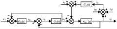
图6附图为本发明提供的电容电流反馈与并网电压比例前馈控制框图;6 is a block diagram of the capacitive current feedback and grid-connected voltage proportional feedforward control provided by the present invention;
图7附图为本发明提供的电容电流反馈与并网电压比例前馈控制频率特性分布图;Fig. 7 accompanying drawing is the frequency characteristic distribution diagram of capacitive current feedback and grid-connected voltage proportional feedforward control provided by the present invention;
图8附图为本发明提供的电容电流反馈与并网电压比例前馈控制根轨迹分布图;Fig. 8 accompanying drawing is the root locus distribution diagram of capacitive current feedback and grid-connected voltage proportional feedforward control provided by the present invention;
图9附图为本发明提供的RLC电路原理图;Fig. 9 accompanying drawing is the RLC circuit schematic diagram provided by the present invention;
图10附图为本发明提供的全局谐振抑制策略控制框图;The accompanying drawing of FIG. 10 is a control block diagram of a global resonance suppression strategy provided by the present invention;
图11附图为本发明提供的基于混合阻尼谐振抑制策略频率特性;Fig. 11 is the frequency characteristic based on the hybrid damping resonance suppression strategy provided by the present invention;
图12附图为本发明提供的阻抗变化时有无控制策略对比伯德图;The accompanying drawing of FIG. 12 is a Bode diagram with or without a control strategy when the impedance changes provided by the present invention;
图13附图为本发明提供的无谐振抑制策略并网电流波形分析图;13 is an analysis diagram of the grid-connected current waveform of the non-resonance suppression strategy provided by the present invention;
图14附图为本发明提供的无谐振抑制策略并网电流谐波分析图;Figure 14 is a diagram illustrating the harmonic analysis of grid-connected current provided by the non-resonance suppression strategy provided by the present invention;
图15附图为本发明提供的有谐振抑制策略集群系统并网电流波形分析;15 is an analysis of the grid-connected current waveform of a cluster system with a resonance suppression strategy provided by the present invention;
图16附图为本发明提供的有谐振抑制策略集群系统并网电流谐波分析。FIG. 16 is a diagram showing the harmonic analysis of the grid-connected current of the cluster system with the resonance suppression strategy provided by the present invention.
具体实施方式Detailed ways
下面将结合本发明实施例中的附图,对本发明实施例中的技术方案进行清楚、完整地描述,显然,所描述的实施例仅仅是本发明一部分实施例,而不是全部的实施例。基于本发明中的实施例,本领域普通技术人员在没有做出创造性劳动前提下所获得的所有其他实施例,都属于本发明保护的范围。The technical solutions in the embodiments of the present invention will be clearly and completely described below with reference to the accompanying drawings in the embodiments of the present invention. Obviously, the described embodiments are only a part of the embodiments of the present invention, but not all of the embodiments. Based on the embodiments of the present invention, all other embodiments obtained by those of ordinary skill in the art without creative efforts shall fall within the protection scope of the present invention.
本发明实施例公开了一种基于混合阻尼的全局谐振抑制方法,下面结合具体技术背景对技术方案做进一步解释说明。The embodiment of the present invention discloses a global resonance suppression method based on hybrid damping, and the technical solution is further explained below with reference to the specific technical background.
参见图1,图1为组串式光伏逆变器集群系统结构图,每套光伏并网系统包括光伏电池板、升压电路、逆变器、LCL滤波器和弱电网;PVi为第i个组串式光伏阵列;MPPT为光伏阵列的最大功率点跟踪模块;由直流侧电感Ldci、稳压电容Cdci和二极管、三极管构成的DC/DC变换器与DC/AC变换器组成了两级式变换器,通过LCL滤波器与弱电网相连;ui为第i台逆变器输出电压;iipi为第i台逆变器并网电流;uPCC为公共耦合点电压;Ccpvi为第i个光伏电池板对地寄生电容;弱电网阻抗Zg=Rg+Lg和电网电压ug。iL1i、iL2i、ig分别为逆变器侧电感电流、网侧电感电流、并网电流;RL1i与RL2i为滤波电感的寄生电阻;Ci为滤波电容,uc为电容电压,其中,i=1,2,3…,n。Referring to Figure 1, Figure 1 is a structural diagram of a string photovoltaic inverter cluster system. Each photovoltaic grid-connected system includes photovoltaic panels, booster circuits, inverters, LCL filters and weak grids; PVi is the i-th grid. A string-type photovoltaic array; MPPT is the maximum power point tracking module of the photovoltaic array; the DC/DC converter and the DC/AC converter composed of the DC side inductor Ldci , the voltage-stabilizing capacitor Cdci , diodes and triodes are composed of two The stage converter is connected to the weak grid through the LCL filter; ui is the output voltage of the i-th inverter; iipi is the grid-connected current of the i-th inverter; uPCC is the common coupling point voltage; Ccpvi is The parasitic capacitance of the i-th photovoltaic panel to ground; weak grid impedance Zg =Rg +Lg and grid voltageug . iL1i , iL2i , andig are the inverter-side inductor current, grid-side inductor current, and grid-connected current, respectively; RL1i and RL2i are the parasitic resistances of the filter inductors; Ci is the filter capacitor, uc is the capacitor voltage, where i=1, 2, 3..., n.
组串式光伏集群逆变器并网系统的数学模型为:The mathematical model of the grid-connected system of string photovoltaic cluster inverters is:

由式(12)得3台逆变器并网等效控制框图如图2所示。From the formula (12), the equivalent control block diagram of three inverters connected to the grid is shown in Figure 2.
图中,In the figure,

由图2可知,ui至并网电流ip1的传递函数为It can be seen from Figure 2 that the transfer function from ui to grid-connected current ip1 is

式中,In the formula,

由式(1)得出系统有两个谐振点,即According to formula (1), the system has two resonance points, namely

从图3可以看出,系统有两个谐振峰:一个是fLCLg,与并联台数n和电网阻抗大小相关;一个是fLCL,其值不受电网阻抗与并联台数n影响。图3横轴表示频率,从上到下两幅曲线图中纵轴分别表示幅值和相位。每存在一个谐振尖峰,同时相位发生-180°跳变。从控制角度讲,这个-180°跳变为一次负穿越,它会产生一对右半平面的闭环极点,导致并网系统不稳定。As can be seen from Figure 3, the system has two resonance peaks: one is fLCLg , which is related to the number of parallel units n and the grid impedance; the other is fLCL , whose value is not affected by the grid impedance and the number of parallel units n. The horizontal axis of Fig. 3 represents frequency, and the vertical axis of the two graphs from top to bottom represents amplitude and phase, respectively. Every time there is a resonance peak, the phase jumps by -180° at the same time. From the control point of view, this -180° jump becomes a negative crossing, which produces a pair of closed-loop poles in the right half-plane, resulting in instability of the grid-connected system.
如果并联系统中n台并网逆变器的系统参数和工作条件相同,则每个并网逆变器连接的电网阻抗将放大n倍。因此,组串式光伏集群并网产生的谐振频率为If the system parameters and working conditions of n grid-connected inverters in a parallel system are the same, the grid impedance connected to each grid-connected inverter will be amplified by n times. Therefore, the resonant frequency generated by the grid-connected photovoltaic cluster is

多个逆变器的并网谐振频率特性如图4所示,横轴表示频率,从上到下两幅曲线图中纵坐标分别表示幅值和相位,图中蓝线表示系统3台逆变器并网,红线表示5台逆变器并网,黄线表示16台逆变器并网,紫线表示32台逆变器并网,绿线表示80台逆变器并网。从图4可以看出,随着逆变器并网数量的增加,系统并网产生的谐振点逐渐移向低频段,LCL逆变器自身产生的谐振点不变。The grid-connected resonance frequency characteristics of multiple inverters are shown in Figure 4. The horizontal axis represents the frequency, and the vertical axis represents the amplitude and phase in the two graphs from top to bottom. The blue line in the figure represents the three inverters in the system. The red line indicates that 5 inverters are connected to the grid, the yellow line indicates that 16 inverters are connected to the grid, the purple line indicates that 32 inverters are connected to the grid, and the green line indicates that 80 inverters are connected to the grid. It can be seen from Figure 4 that with the increase of the number of inverters connected to the grid, the resonance point generated by the grid connection of the system gradually moves to the low frequency band, and the resonance point generated by the LCL inverter itself remains unchanged.
由式(14)可知,系统谐振峰的极限频率为From equation (14), it can be known that the limit frequency of the system resonance peak is

由式(15)可知,并网谐振频率与并联逆变器数量的关系如图5所示,横坐标表示逆变器并联数量,纵坐标表示并网谐振频率。随着逆变器并联数量的增加,并网谐振频率逐渐趋于一个固定值,最终谐振频率保持在1.5kHz左右。It can be seen from equation (15) that the relationship between the grid-connected resonant frequency and the number of parallel inverters is shown in Figure 5. The abscissa represents the number of inverters in parallel, and the ordinate represents the grid-connected resonant frequency. As the number of inverters in parallel increases, the grid-connected resonant frequency gradually tends to a fixed value, and the final resonant frequency remains around 1.5kHz.
针对上述问题,本发明提出了一种并网电压比例前馈与电容电流反馈的控制策略,有效提高逆变器控制系统的稳定性,抑制谐振发生。且有效降低硬件成本和功耗,控制框图如图6所示。In view of the above problems, the present invention proposes a control strategy of grid-connected voltage proportional feedforward and capacitive current feedback, which effectively improves the stability of the inverter control system and suppresses the occurrence of resonance. And effectively reduce hardware cost and power consumption, the control block diagram is shown in Figure 6.
图6中,系统输入电流i*,输出电流ip1。电容电流ic通过反馈对系统进行补偿,消除由并网引起的电流滞后。逆变器等效增益KPWM=1。Kd为有源阻尼系数,Gf为比例反馈系数,GPR(s)为准PR电流控制器,在PR控制器中加入谐波补偿环节,可抑制电网波动导致的谐波。In Fig. 6, the system input current i* and output current ip1 . The capacitive currentic compensates the system through feedback, eliminating the current lag caused by grid connection. The inverter equivalent gain KPWM =1. Kd is the active damping coefficient, Gf is the proportional feedback coefficient, and GPR (s) is a quasi-PR current controller. Adding a harmonic compensation link to the PR controller can suppress harmonics caused by power grid fluctuations.
PR控制器的形式如下The PR controller has the following form

式中,kp、kr、ω1、ωc分别表示准PR电流控制器的比例增益、广义积分系数、谐振角频率及控制器带宽。where kp, kr, ω1, and ωc represent the proportional gain, generalized integral coefficient, resonant angular frequency and controller bandwidth of the quasi-PR current controller, respectively.
系统的开环传递函数为The open-loop transfer function of the system is

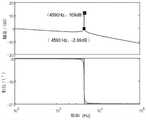
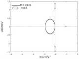
系统的频率特性曲线和根轨迹如图7-8所示。在图7中,有无策略对比发现,蓝线表示无策略,红线表示有策略,电流谐振点峰值由109dB降至-2.09dB,说明电容电流反馈和电网电压前馈控制策略能有效抑制系统谐振;图8中,蓝色曲线表示根轨迹曲线,绿色闭合环表示分离点,系统根轨迹分布在复平面的左半平面上,证明该控制策略理论上能保证系统的稳定运行。The frequency characteristic curve and root locus of the system are shown in Figure 7-8. In Figure 7, the comparison with and without strategy shows that the blue line indicates no strategy, the red line indicates strategy, and the peak value of the current resonance point decreases from 109dB to -2.09dB, indicating that the capacitive current feedback and grid voltage feedforward control strategy can effectively suppress the system resonance ; In Figure 8, the blue curve represents the root locus curve, the green closed loop represents the separation point, and the system root locus is distributed on the left half plane of the complex plane, which proves that the control strategy can theoretically ensure the stable operation of the system.
针对集群逆变器并联引起的系统级谐振,提出了一种改进的全局谐振抑制控制策略。在PCC点处设计了一种并联二阶RLC谐振抑制电路。二阶RLC谐振抑制电路的原理如图9所示。Aiming at the system-level resonance caused by the parallel connection of cluster inverters, an improved global resonance suppression control strategy is proposed. A parallel second-order RLC resonance suppression circuit is designed at the PCC point. The principle of the second-order RLC resonance suppression circuit is shown in Figure 9.
在图9中,二阶RLC谐振抑制电路用于尽可能减少高频谐波信号,使对低频补偿信号的影响最小,并使谐振峰值最小。Rd增加系统的阻尼,减小并网电流的谐波导致的谐振尖峰;Cd作用是降低系统损耗;ud为RLC电路的端电压,id为流入RLC谐振抑制电路电流。In Figure 9, a second-order RLC resonance suppression circuit is used to minimize high-frequency harmonic signals, minimize the impact on low-frequency compensation signals, and minimize resonance peaks. Rd increases the damping of the system and reduces the resonance peak caused by the harmonics of the grid-connected current; Cd reduces system losses;ud is the terminal voltage of the RLC circuit, andid is the current flowing into the RLC resonance suppression circuit.
由式(14)得谐振抑制电路的谐振频率为From equation (14), the resonance frequency of the resonance suppression circuit can be obtained as

结合式(8)推导出L、C、R约束条件为Combined with formula (8), the L, C, R constraints are deduced as

式中,f=50Hz,ω=2πf。In the formula, f=50Hz, ω=2πf.
由图9得集群并网系统得数学模型为The mathematical model of the cluster grid-connected system obtained from Figure 9 is

由式(16)可得集群系统控制框图如图10所示。图中Gd(s)为二阶RLC谐振抑制电路等效阻抗拉普拉斯变换,
图11为集群系统的频率特性曲,横坐标表示频率,纵坐标从上到下依次表示幅值和相位,蓝线表示无策略系统逆变器频率特性,红线表示有策略系统逆变器频率特性。图11中,加入控制策略前,逆变器的谐振峰值为109dB,并网集群系统的谐振峰值为131dB。通过增加电容电流反馈和电网电压前馈控制,逆变器的谐振峰值降低到-48dB;加入RLC二阶谐振抑制电路后,集群系统并网谐振峰值降低到-19.8dB。因此,本文所提策略理论上能够有效抑制集群逆变器谐振。Figure 11 is the frequency characteristic curve of the cluster system. The abscissa represents the frequency, and the ordinate represents the amplitude and phase from top to bottom. The blue line represents the frequency characteristic of the inverter in the non-strategy system, and the red line represents the frequency characteristic of the inverter in the strategic system. . In Figure 11, before adding the control strategy, the resonance peak value of the inverter is 109dB, and the resonance peak value of the grid-connected cluster system is 131dB. By adding capacitor current feedback and grid voltage feedforward control, the resonance peak value of the inverter is reduced to -48dB; after adding the RLC second-order resonance suppression circuit, the grid-connected resonance peak value of the cluster system is reduced to -19.8dB. Therefore, the strategy proposed in this paper can theoretically effectively suppress the resonance of cluster inverters.
图12为系统等效开环在不同电网阻抗下的变化曲线,横坐标表示频率,纵坐标从上到下依次表示幅值和相位。从图12(a)可知,未加入谐振抑制策略时,随着电网等效阻抗Lg的增加,系统的截止频率和相位裕度逐渐减小,系统的动态性能逐渐变差,蓝线表示Lg=1.2mH,红线表示Lg=0.1mH,黄线表示Lg=0mH。但是和图12(b)所示的有加入谐振抑制策略的伯德图相比,系统一直处于稳定状态,说明在加入电容电流反馈与并网电压比例前馈和RLC型谐振抑制电路相结合的全局谐振抑制策略后系统的稳定性得到了提高。Figure 12 shows the change curve of the equivalent open loop of the system under different grid impedances. The abscissa represents the frequency, and the ordinate represents the amplitude and phase from top to bottom. It can be seen from Figure 12(a) that when the resonance suppression strategy is not added, with the increase of the grid equivalent impedance Lg , the cut-off frequency and phase margin of the system gradually decrease, and the dynamic performance of the system gradually deteriorates. The blue line represents Lg = 1.2 mH, the red line indicates Lg =0.1 mH, and the yellow line indicates Lg =0 mH. However, compared with the Bode diagram with the resonance suppression strategy shown in Figure 12(b), the system has been in a stable state, indicating that the system is in a stable state when the capacitor current feedback is added, the grid-connected voltage proportional feedforward and the RLC resonance suppression circuit are combined. The stability of the system is improved after the global resonance suppression strategy.
下面结合仿真来验证本发明提供的控制方法的正确性。The correctness of the control method provided by the present invention is verified below in conjunction with simulation.
为了验证所提控制方法的正确性,采用matalab进行仿真。仿真参数如表1所示。In order to verify the correctness of the proposed control method, Matalab is used for simulation. The simulation parameters are shown in Table 1.
表1组串式光伏集群系统参数Table 1 String photovoltaic cluster system parameters

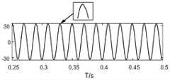
从图15-16可以看出,电流波形已发生畸变,并网电流总谐波失真率(THD)为10.54%,其中39次谐波(集群并网谐振)和92次谐波(逆变器自谐振)含量很高,THD分别为3.2%和3.6%。As can be seen from Figure 15-16, the current waveform has been distorted, and the total harmonic distortion (THD) of the grid-connected current is 10.54%, of which the 39th harmonic (cluster grid-connected resonance) and the 92nd harmonic (inverter Self-resonance) content is high, with THD of 3.2% and 3.6%, respectively.
PR电流调节器的参数如表2所示。The parameters of the PR current regulator are shown in Table 2.
表2PR电流调节器参数Table 2PR current regulator parameters

R=50Ω,L=0.1mH,C=0.4μF,加入全局谐振抑制策略,并网电流波形和FFT谐波分析如图16所示,横坐标表示谐波次数,纵坐标表示幅值与基波之比。R=50Ω, L=0.1mH, C=0.4μF, adding the global resonance suppression strategy, the grid-connected current waveform and FFT harmonic analysis are shown in Figure 16, the abscissa represents the harmonic order, and the ordinate represents the amplitude and fundamental wave Ratio.
从图16可以看出,并网电流的THD为1.97%,与未加入谐振抑制策略THD相比,下降程度高达81.3%,因此THD得到显著抑制,其中92次谐波和39次谐波分别为0.05%、0.03%,与未加入谐振抑制策略THD相比,下降程度分别为98.44%、99.17%,说明该策略能够有效抑制组串式光伏集群逆变器并联并网产生的谐振。It can be seen from Figure 16 that the THD of the grid-connected current is 1.97%, which is as high as 81.3% compared with the THD without the resonance suppression strategy, so the THD is significantly suppressed. The 92nd harmonic and the 39th harmonic are respectively 0.05% and 0.03%, compared with the THD without the resonance suppression strategy, the reduction degrees are 98.44% and 99.17%, respectively, indicating that this strategy can effectively suppress the resonance generated by the parallel connection of the string photovoltaic cluster inverters.
为验证系统在电网强弱下的稳定性,对系统在电网阻抗变化下的情况仿真,仿真结果如表3所示。由表3数据显示,电网阻抗在0~1.2mH范围内系统均能稳定运行,本发明所提控制策略可以有效提高弱电网下集群并网系统的稳定性,证明了策略的有效性。In order to verify the stability of the system under the power grid strength, the situation of the system under the change of power grid impedance is simulated, and the simulation results are shown in Table 3. The data in Table 3 shows that the system can operate stably in the range of grid impedance of 0-1.2mH. The control strategy proposed in the present invention can effectively improve the stability of the cluster grid-connected system under weak grids, proving the effectiveness of the strategy.
表3电网阻抗变化仿真结果Table 3. Simulation results of grid impedance change


综上所述,本发明首先分析了集群逆变器的数学模型、谐振机理与谐振特性,提出一种基于混合阻尼的全局谐振抑制策略。该策略在逆变器电流环中引入电容电流反馈与并网电压比例前馈作为有源阻尼,以削弱并网电流的谐波;在此基础上加入二阶RLC谐振抑制电路作为无源阻尼,以抑制系统谐振,使集群并网时逆变器输出电流满足并网条件。最后进行了验证,证明了相关理论分析和所提出控制策略的正确性和有效性。To sum up, the present invention first analyzes the mathematical model, resonance mechanism and resonance characteristics of the cluster inverter, and proposes a global resonance suppression strategy based on hybrid damping. This strategy introduces capacitive current feedback and grid-connected voltage proportional feedforward as active damping in the inverter current loop to weaken the harmonics of grid-connected current; on this basis, a second-order RLC resonance suppression circuit is added as passive damping, In order to suppress the system resonance, the inverter output current can meet the grid connection conditions when the cluster is connected to the grid. Finally, the verification is carried out to prove the correctness and effectiveness of the relevant theoretical analysis and the proposed control strategy.
本说明书中各个实施例采用递进的方式描述,每个实施例重点说明的都是与其他实施例的不同之处,各个实施例之间相同相似部分互相参见即可。对于实施例公开的装置而言,由于其与实施例公开的方法相对应,所以描述的比较简单,相关之处参见方法部分说明即可。The various embodiments in this specification are described in a progressive manner, and each embodiment focuses on the differences from other embodiments, and the same and similar parts between the various embodiments can be referred to each other. As for the device disclosed in the embodiment, since it corresponds to the method disclosed in the embodiment, the description is relatively simple, and the relevant part can be referred to the description of the method.
对所公开的实施例的上述说明,使本领域专业技术人员能够实现或使用本发明。对这些实施例的多种修改对本领域的专业技术人员来说将是显而易见的,本文中所定义的一般原理可以在不脱离本发明的精神或范围的情况下,在其它实施例中实现。因此,本发明将不会被限制于本文所示的这些实施例,而是要符合与本文所公开的原理和新颖特点相一致的最宽的范围。The above description of the disclosed embodiments enables any person skilled in the art to make or use the present invention. Various modifications to these embodiments will be readily apparent to those skilled in the art, and the generic principles defined herein may be implemented in other embodiments without departing from the spirit or scope of the invention. Thus, the present invention is not intended to be limited to the embodiments shown herein, but is to be accorded the widest scope consistent with the principles and novel features disclosed herein.
Claims (4)


Priority Applications (1)
| Application Number | Priority Date | Filing Date | Title |
|---|---|---|---|
| CN202110501964.4ACN113258564B (en) | 2021-05-08 | 2021-05-08 | Group string type photovoltaic cluster inverter grid-connected resonance suppression method based on hybrid damping |
Applications Claiming Priority (1)
| Application Number | Priority Date | Filing Date | Title |
|---|---|---|---|
| CN202110501964.4ACN113258564B (en) | 2021-05-08 | 2021-05-08 | Group string type photovoltaic cluster inverter grid-connected resonance suppression method based on hybrid damping |
Publications (2)
| Publication Number | Publication Date |
|---|---|
| CN113258564A CN113258564A (en) | 2021-08-13 |
| CN113258564Btrue CN113258564B (en) | 2022-09-09 |
Family
ID=77222251
Family Applications (1)
| Application Number | Title | Priority Date | Filing Date |
|---|---|---|---|
| CN202110501964.4AActiveCN113258564B (en) | 2021-05-08 | 2021-05-08 | Group string type photovoltaic cluster inverter grid-connected resonance suppression method based on hybrid damping |
Country Status (1)
| Country | Link |
|---|---|
| CN (1) | CN113258564B (en) |
Families Citing this family (3)
| Publication number | Priority date | Publication date | Assignee | Title |
|---|---|---|---|---|
| CN114336747B (en)* | 2021-12-29 | 2023-07-21 | 湖南工业大学 | A photovoltaic inverter cluster resonance active damping frequency division control method |
| CN114597946A (en)* | 2022-03-19 | 2022-06-07 | 湖南工业大学 | Layered cooperative control method and grid-connected system for cluster of string-type photovoltaic inverters |
| CN116247913A (en)* | 2023-03-28 | 2023-06-09 | 华中科技大学 | A Design Method of Hybrid Damping Parameters Based on Pole Position Optimization |
Citations (4)
| Publication number | Priority date | Publication date | Assignee | Title |
|---|---|---|---|---|
| CN103545838A (en)* | 2013-09-17 | 2014-01-29 | 南京航空航天大学 | A hybrid damping adaptive control method for grid-connected inverters suitable for weak grid access conditions |
| CN108123447A (en)* | 2016-11-29 | 2018-06-05 | 赵吉彬 | A kind of quasi- ratio resonance of novel photovoltaic grid-connected inverter inhibits strategy |
| CN110912135A (en)* | 2019-12-04 | 2020-03-24 | 武汉理工大学 | A Design Method of Grid-connected Inverter LLCL Hybrid Damping Filter |
| CN111082440A (en)* | 2020-01-15 | 2020-04-28 | 湖南工业大学 | Group string type photovoltaic inverter resonance suppression method based on self-adaptive notch |
Family Cites Families (1)
| Publication number | Priority date | Publication date | Assignee | Title |
|---|---|---|---|---|
| US10333390B2 (en)* | 2015-05-08 | 2019-06-25 | The Board Of Trustees Of The University Of Alabama | Systems and methods for providing vector control of a grid connected converter with a resonant circuit grid filter |
- 2021
- 2021-05-08CNCN202110501964.4Apatent/CN113258564B/enactiveActive
Patent Citations (4)
| Publication number | Priority date | Publication date | Assignee | Title |
|---|---|---|---|---|
| CN103545838A (en)* | 2013-09-17 | 2014-01-29 | 南京航空航天大学 | A hybrid damping adaptive control method for grid-connected inverters suitable for weak grid access conditions |
| CN108123447A (en)* | 2016-11-29 | 2018-06-05 | 赵吉彬 | A kind of quasi- ratio resonance of novel photovoltaic grid-connected inverter inhibits strategy |
| CN110912135A (en)* | 2019-12-04 | 2020-03-24 | 武汉理工大学 | A Design Method of Grid-connected Inverter LLCL Hybrid Damping Filter |
| CN111082440A (en)* | 2020-01-15 | 2020-04-28 | 湖南工业大学 | Group string type photovoltaic inverter resonance suppression method based on self-adaptive notch |
Non-Patent Citations (1)
| Title |
|---|
| 基于虚拟电阻的并网逆变器谐振抑制措施的研究;慕昆等;《可再生能源》;20160620(第06期);全文* |
Also Published As
| Publication number | Publication date |
|---|---|
| CN113258564A (en) | 2021-08-13 |
Similar Documents
| Publication | Publication Date | Title |
|---|---|---|
| CN110148943B (en) | LCL grid-connected inverter impedance remodeling method for inhibiting power grid background harmonic influence | |
| CN113285624B (en) | An Active Damping High-Frequency Resonance Suppression Method | |
| CN113258564B (en) | Group string type photovoltaic cluster inverter grid-connected resonance suppression method based on hybrid damping | |
| CN108471124B (en) | Resonance suppression method for photovoltaic inverter to be connected into alternating current-direct current hybrid micro-grid | |
| CN111245004B (en) | Composite robust control method of high-frequency SiC photovoltaic grid-connected inverter under weak current network | |
| CN109038581B (en) | Impedance remodeling type harmonic current suppression method for VSG | |
| CN110718934A (en) | LLCL grid-connected inverter resonance suppression method adapting to power grid impedance change | |
| CN110086171A (en) | A kind of gird-connected inverter resonance suppressing method and device enhancing system rejection to disturbance ability | |
| CN106712099A (en) | Multi-parallel photovoltaic grid-connected inverter design method | |
| CN111490539B (en) | A Resonance Suppression Method for Photovoltaic Inverter Clusters Based on Active Harmonic Conductance Method | |
| CN115347616B (en) | Damping mutual-aid control method of new energy grid-connected inverter | |
| CN107895966A (en) | The light current electric voltage feed forward lag compensation control method off the net based on impedance self-adaptive | |
| CN113285625A (en) | Photovoltaic inverter cluster resonance suppression method based on improved active damping method | |
| CN107834594A (en) | The light current voltage feed-forward control control method off the net based on weighing first order inertial element | |
| CN115995813A (en) | Grid-connected inverter oscillation suppression strategy based on hybrid damping | |
| CN116316625A (en) | Global Resonance Suppression Method and System for LCL Inverter Multi-machine Parallel System | |
| CN108258702B (en) | A Resonance Suppression Method of Grid-Connected Converter Considering the Distributed Capacitance of Transmission Line | |
| CN114844041B (en) | Feedforward control method to enhance system stability and filter out high-order background harmonics in power grid | |
| CN110266017B (en) | Hybrid state feedback virtual damping control method for LCL (lower control limit) type active power filter | |
| CN115207968A (en) | Method for improving stability margin of photovoltaic grid-connected inverter under weak grid | |
| CN115378040A (en) | A grid-connected system and QVR control method based on LCL photovoltaic inverter | |
| CN114285081A (en) | Wide area power system stabilizing method based on self-adaptive virtual resistance | |
| CN110247429B (en) | Analysis method for voltage feedforward control photovoltaic power generation considering coupling | |
| Zhong et al. | A new damping scheme of llcl filter for grid-tied pv inverter output harmonics mitigation | |
| CN117691671A (en) | A photovoltaic inverter impedance model construction method adapted to cluster parameter adjustment |
Legal Events
| Date | Code | Title | Description |
|---|---|---|---|
| PB01 | Publication | ||
| PB01 | Publication | ||
| SE01 | Entry into force of request for substantive examination | ||
| SE01 | Entry into force of request for substantive examination | ||
| GR01 | Patent grant | ||
| GR01 | Patent grant |