CN113242786B - Three-dimensional printing device System and method - Google Patents
Three-dimensional printing device System and methodDownload PDFInfo
- Publication number
- CN113242786B CN113242786BCN201980075259.3ACN201980075259ACN113242786BCN 113242786 BCN113242786 BCN 113242786BCN 201980075259 ACN201980075259 ACN 201980075259ACN 113242786 BCN113242786 BCN 113242786B
- Authority
- CN
- China
- Prior art keywords
- extruder
- axis
- cam
- follower
- build
- Prior art date
- Legal status (The legal status is an assumption and is not a legal conclusion. Google has not performed a legal analysis and makes no representation as to the accuracy of the status listed.)
- Active
Links
Images


Classifications
- B—PERFORMING OPERATIONS; TRANSPORTING
- B29—WORKING OF PLASTICS; WORKING OF SUBSTANCES IN A PLASTIC STATE IN GENERAL
- B29C—SHAPING OR JOINING OF PLASTICS; SHAPING OF MATERIAL IN A PLASTIC STATE, NOT OTHERWISE PROVIDED FOR; AFTER-TREATMENT OF THE SHAPED PRODUCTS, e.g. REPAIRING
- B29C64/00—Additive manufacturing, i.e. manufacturing of three-dimensional [3D] objects by additive deposition, additive agglomeration or additive layering, e.g. by 3D printing, stereolithography or selective laser sintering
- B29C64/10—Processes of additive manufacturing
- B29C64/106—Processes of additive manufacturing using only liquids or viscous materials, e.g. depositing a continuous bead of viscous material
- B29C64/118—Processes of additive manufacturing using only liquids or viscous materials, e.g. depositing a continuous bead of viscous material using filamentary material being melted, e.g. fused deposition modelling [FDM]
- B—PERFORMING OPERATIONS; TRANSPORTING
- B29—WORKING OF PLASTICS; WORKING OF SUBSTANCES IN A PLASTIC STATE IN GENERAL
- B29C—SHAPING OR JOINING OF PLASTICS; SHAPING OF MATERIAL IN A PLASTIC STATE, NOT OTHERWISE PROVIDED FOR; AFTER-TREATMENT OF THE SHAPED PRODUCTS, e.g. REPAIRING
- B29C64/00—Additive manufacturing, i.e. manufacturing of three-dimensional [3D] objects by additive deposition, additive agglomeration or additive layering, e.g. by 3D printing, stereolithography or selective laser sintering
- B29C64/20—Apparatus for additive manufacturing; Details thereof or accessories therefor
- B29C64/205—Means for applying layers
- B29C64/209—Heads; Nozzles
- B—PERFORMING OPERATIONS; TRANSPORTING
- B29—WORKING OF PLASTICS; WORKING OF SUBSTANCES IN A PLASTIC STATE IN GENERAL
- B29C—SHAPING OR JOINING OF PLASTICS; SHAPING OF MATERIAL IN A PLASTIC STATE, NOT OTHERWISE PROVIDED FOR; AFTER-TREATMENT OF THE SHAPED PRODUCTS, e.g. REPAIRING
- B29C64/00—Additive manufacturing, i.e. manufacturing of three-dimensional [3D] objects by additive deposition, additive agglomeration or additive layering, e.g. by 3D printing, stereolithography or selective laser sintering
- B29C64/20—Apparatus for additive manufacturing; Details thereof or accessories therefor
- B29C64/227—Driving means
- B29C64/232—Driving means for motion along the axis orthogonal to the plane of a layer
- B—PERFORMING OPERATIONS; TRANSPORTING
- B29—WORKING OF PLASTICS; WORKING OF SUBSTANCES IN A PLASTIC STATE IN GENERAL
- B29C—SHAPING OR JOINING OF PLASTICS; SHAPING OF MATERIAL IN A PLASTIC STATE, NOT OTHERWISE PROVIDED FOR; AFTER-TREATMENT OF THE SHAPED PRODUCTS, e.g. REPAIRING
- B29C64/00—Additive manufacturing, i.e. manufacturing of three-dimensional [3D] objects by additive deposition, additive agglomeration or additive layering, e.g. by 3D printing, stereolithography or selective laser sintering
- B29C64/20—Apparatus for additive manufacturing; Details thereof or accessories therefor
- B29C64/227—Driving means
- B29C64/236—Driving means for motion in a direction within the plane of a layer
- B—PERFORMING OPERATIONS; TRANSPORTING
- B29—WORKING OF PLASTICS; WORKING OF SUBSTANCES IN A PLASTIC STATE IN GENERAL
- B29C—SHAPING OR JOINING OF PLASTICS; SHAPING OF MATERIAL IN A PLASTIC STATE, NOT OTHERWISE PROVIDED FOR; AFTER-TREATMENT OF THE SHAPED PRODUCTS, e.g. REPAIRING
- B29C64/00—Additive manufacturing, i.e. manufacturing of three-dimensional [3D] objects by additive deposition, additive agglomeration or additive layering, e.g. by 3D printing, stereolithography or selective laser sintering
- B29C64/20—Apparatus for additive manufacturing; Details thereof or accessories therefor
- B29C64/245—Platforms or substrates
- B—PERFORMING OPERATIONS; TRANSPORTING
- B29—WORKING OF PLASTICS; WORKING OF SUBSTANCES IN A PLASTIC STATE IN GENERAL
- B29C—SHAPING OR JOINING OF PLASTICS; SHAPING OF MATERIAL IN A PLASTIC STATE, NOT OTHERWISE PROVIDED FOR; AFTER-TREATMENT OF THE SHAPED PRODUCTS, e.g. REPAIRING
- B29C64/00—Additive manufacturing, i.e. manufacturing of three-dimensional [3D] objects by additive deposition, additive agglomeration or additive layering, e.g. by 3D printing, stereolithography or selective laser sintering
- B29C64/20—Apparatus for additive manufacturing; Details thereof or accessories therefor
- B29C64/295—Heating elements
- B—PERFORMING OPERATIONS; TRANSPORTING
- B29—WORKING OF PLASTICS; WORKING OF SUBSTANCES IN A PLASTIC STATE IN GENERAL
- B29C—SHAPING OR JOINING OF PLASTICS; SHAPING OF MATERIAL IN A PLASTIC STATE, NOT OTHERWISE PROVIDED FOR; AFTER-TREATMENT OF THE SHAPED PRODUCTS, e.g. REPAIRING
- B29C64/00—Additive manufacturing, i.e. manufacturing of three-dimensional [3D] objects by additive deposition, additive agglomeration or additive layering, e.g. by 3D printing, stereolithography or selective laser sintering
- B29C64/30—Auxiliary operations or equipment
- B29C64/307—Handling of material to be used in additive manufacturing
- B29C64/321—Feeding
- B—PERFORMING OPERATIONS; TRANSPORTING
- B29—WORKING OF PLASTICS; WORKING OF SUBSTANCES IN A PLASTIC STATE IN GENERAL
- B29C—SHAPING OR JOINING OF PLASTICS; SHAPING OF MATERIAL IN A PLASTIC STATE, NOT OTHERWISE PROVIDED FOR; AFTER-TREATMENT OF THE SHAPED PRODUCTS, e.g. REPAIRING
- B29C64/00—Additive manufacturing, i.e. manufacturing of three-dimensional [3D] objects by additive deposition, additive agglomeration or additive layering, e.g. by 3D printing, stereolithography or selective laser sintering
- B29C64/30—Auxiliary operations or equipment
- B29C64/35—Cleaning
- B—PERFORMING OPERATIONS; TRANSPORTING
- B29—WORKING OF PLASTICS; WORKING OF SUBSTANCES IN A PLASTIC STATE IN GENERAL
- B29C—SHAPING OR JOINING OF PLASTICS; SHAPING OF MATERIAL IN A PLASTIC STATE, NOT OTHERWISE PROVIDED FOR; AFTER-TREATMENT OF THE SHAPED PRODUCTS, e.g. REPAIRING
- B29C64/00—Additive manufacturing, i.e. manufacturing of three-dimensional [3D] objects by additive deposition, additive agglomeration or additive layering, e.g. by 3D printing, stereolithography or selective laser sintering
- B29C64/30—Auxiliary operations or equipment
- B29C64/379—Handling of additively manufactured objects, e.g. using robots
- B—PERFORMING OPERATIONS; TRANSPORTING
- B29—WORKING OF PLASTICS; WORKING OF SUBSTANCES IN A PLASTIC STATE IN GENERAL
- B29C—SHAPING OR JOINING OF PLASTICS; SHAPING OF MATERIAL IN A PLASTIC STATE, NOT OTHERWISE PROVIDED FOR; AFTER-TREATMENT OF THE SHAPED PRODUCTS, e.g. REPAIRING
- B29C64/00—Additive manufacturing, i.e. manufacturing of three-dimensional [3D] objects by additive deposition, additive agglomeration or additive layering, e.g. by 3D printing, stereolithography or selective laser sintering
- B29C64/30—Auxiliary operations or equipment
- B29C64/386—Data acquisition or data processing for additive manufacturing
- B29C64/393—Data acquisition or data processing for additive manufacturing for controlling or regulating additive manufacturing processes
- B—PERFORMING OPERATIONS; TRANSPORTING
- B33—ADDITIVE MANUFACTURING TECHNOLOGY
- B33Y—ADDITIVE MANUFACTURING, i.e. MANUFACTURING OF THREE-DIMENSIONAL [3-D] OBJECTS BY ADDITIVE DEPOSITION, ADDITIVE AGGLOMERATION OR ADDITIVE LAYERING, e.g. BY 3-D PRINTING, STEREOLITHOGRAPHY OR SELECTIVE LASER SINTERING
- B33Y10/00—Processes of additive manufacturing
- B—PERFORMING OPERATIONS; TRANSPORTING
- B33—ADDITIVE MANUFACTURING TECHNOLOGY
- B33Y—ADDITIVE MANUFACTURING, i.e. MANUFACTURING OF THREE-DIMENSIONAL [3-D] OBJECTS BY ADDITIVE DEPOSITION, ADDITIVE AGGLOMERATION OR ADDITIVE LAYERING, e.g. BY 3-D PRINTING, STEREOLITHOGRAPHY OR SELECTIVE LASER SINTERING
- B33Y30/00—Apparatus for additive manufacturing; Details thereof or accessories therefor
- B—PERFORMING OPERATIONS; TRANSPORTING
- B33—ADDITIVE MANUFACTURING TECHNOLOGY
- B33Y—ADDITIVE MANUFACTURING, i.e. MANUFACTURING OF THREE-DIMENSIONAL [3-D] OBJECTS BY ADDITIVE DEPOSITION, ADDITIVE AGGLOMERATION OR ADDITIVE LAYERING, e.g. BY 3-D PRINTING, STEREOLITHOGRAPHY OR SELECTIVE LASER SINTERING
- B33Y40/00—Auxiliary operations or equipment, e.g. for material handling
- B—PERFORMING OPERATIONS; TRANSPORTING
- B33—ADDITIVE MANUFACTURING TECHNOLOGY
- B33Y—ADDITIVE MANUFACTURING, i.e. MANUFACTURING OF THREE-DIMENSIONAL [3-D] OBJECTS BY ADDITIVE DEPOSITION, ADDITIVE AGGLOMERATION OR ADDITIVE LAYERING, e.g. BY 3-D PRINTING, STEREOLITHOGRAPHY OR SELECTIVE LASER SINTERING
- B33Y50/00—Data acquisition or data processing for additive manufacturing
- B33Y50/02—Data acquisition or data processing for additive manufacturing for controlling or regulating additive manufacturing processes
- B—PERFORMING OPERATIONS; TRANSPORTING
- B29—WORKING OF PLASTICS; WORKING OF SUBSTANCES IN A PLASTIC STATE IN GENERAL
- B29C—SHAPING OR JOINING OF PLASTICS; SHAPING OF MATERIAL IN A PLASTIC STATE, NOT OTHERWISE PROVIDED FOR; AFTER-TREATMENT OF THE SHAPED PRODUCTS, e.g. REPAIRING
- B29C64/00—Additive manufacturing, i.e. manufacturing of three-dimensional [3D] objects by additive deposition, additive agglomeration or additive layering, e.g. by 3D printing, stereolithography or selective laser sintering
- B29C64/10—Processes of additive manufacturing
- B29C64/171—Processes of additive manufacturing specially adapted for manufacturing multiple 3D objects
- B29C64/182—Processes of additive manufacturing specially adapted for manufacturing multiple 3D objects in parallel batches
Landscapes
- Engineering & Computer Science (AREA)
- Chemical & Material Sciences (AREA)
- Materials Engineering (AREA)
- Manufacturing & Machinery (AREA)
- Physics & Mathematics (AREA)
- Mechanical Engineering (AREA)
- Optics & Photonics (AREA)
- Robotics (AREA)
Abstract
Description
Translated fromChinese相关申请的交叉引用Cross References to Related Applications
该申请要求享有于2018年9月14日提交的编号为62/731,551的美国临时申请和于2018年12月10日提交的编号为62/777,587的美国临时申请的优先权,其中前述申请中的每个的全部内容由此通过引用并入。This application claims the benefit of U.S. Provisional Application No. 62/731,551, filed September 14, 2018, and U.S. Provisional Application No. 62/777,587, filed December 10, 2018, in which The entire content of each is hereby incorporated by reference.
技术领域technical field
本公开大体上涉及三维打印。The present disclosure generally relates to three-dimensional printing.
背景技术Background technique
已经设计出各种三维制造技术来支持由计算机模型的快速原型制作。多年来,对这些技术进行改进,以提高准确性、工作量以及在快速原型环境中可用的各种构建材料。尽管这些日益复杂和昂贵的机器经常出现在商业设计和工程环境中,已经出现适用于业余爱好者和家庭用户的低成本三维原型制作装置的最新趋势。随着这些资源变得更容易和广泛地可用,已经出现对三维打印的改进的需求,例如,专门为业余爱好者和家庭用户量身定制的改进。Various three-dimensional manufacturing techniques have been devised to support rapid prototyping from computer models. Over the years, these techniques have been refined to increase accuracy, effort, and the variety of build materials available in a rapid prototyping environment. While these increasingly complex and expensive machines are often found in commercial design and engineering settings, there has been a recent trend toward low-cost 3D prototyping devices for hobbyists and home users. As these resources become more readily and widely available, there has been a need for improvements in 3D printing, for example, those tailored specifically for hobbyists and home users.
多挤压机组件典型地采用一些类型的高度控制机构,使得非活动挤压机可升高(或活动挤压机降低,或两者),以避免干扰由其活动挤压机对应物沉积的材料层。然而,在该上下文中,在不同的挤压机之间切换可能很麻烦,且可需要额外的硬件、控制复杂性等。此外,物理高度调整可产生明显的噪声和振动,这些噪声和振动可损坏打印机构件或在打印期间产生不需要的背景噪声。仍需要具有改善的高度控制的多挤压机打印机。Multiple extruder assemblies typically employ some type of height control mechanism such that an inactive extruder can be raised (or an active extruder lowered, or both) to avoid interfering with the flow deposited by its active extruder counterpart. material layer. In this context, however, switching between different extruders may be cumbersome and may require additional hardware, control complexity, and the like. Additionally, physical height adjustments can create significant noise and vibration that can damage printer components or create unwanted background noise during printing. There remains a need for multi-extrusion printers with improved height control.
一种用于三维打印机的挤压机可限定与加热器热连通的室,该加热器将构建材料加热到高于构建材料液化温度的目标温度,且熔化的构建材料可在三维打印期间移动通过挤压机的喷嘴以形成物体。当加热器将构建材料加热到目标温度时,加热器可不希望地加热挤压机的其它部分,在这些地方,此类热量可造成损坏。例如,在挤压机的入口和/或出口附近经历的过多热量可损坏位于这些孔口上或附近的构件。仍需要改进用于三维打印机的挤压机的热管理。An extruder for a three-dimensional printer may define a chamber in thermal communication with a heater that heats a build material to a target temperature above the liquefaction temperature of the build material and through which the molten build material may move during three-dimensional printing The nozzle of the extruder to form the object. While the heater heats the build material to the target temperature, the heater can undesirably heat other parts of the extruder where such heat can cause damage. For example, excessive heat experienced near the inlet and/or outlet of an extruder can damage components located on or near these orifices. There is still a need to improve the thermal management of extruders for 3D printers.
用于三维打印机的构建板大体上为制造物体提供稳定的水平表面。然而,为该目的所设计的构建板通常忽略用户友好特征,其提高舒适性、易于装卸、易于移除打印零件等。仍需要改进用于三维打印机的构建板。Build plates for three-dimensional printers generally provide a stable, horizontal surface on which to fabricate objects. However, build plates designed for this purpose often ignore user-friendly features that enhance comfort, ease of handling, ease of removal of printed parts, and the like. There is still a need to improve build plates for use in 3D printers.
用于三维打印机的挤压机需要例行维护以及对技术问题的定期解决,在此期间,用户需要就地处理挤压机或将挤压机从打印机移除以用于维修。在该上下文中,挤压机的热端——挤压加热的构建材料所通过的尖端——可带来安全问题。在使用期间,热端也容易发生飞溅、弄脏和其它不希望的构建材料堆积。仍需要解决这些问题的挤压机盖。Extruders for 3D printers require routine maintenance as well as periodic resolution of technical issues, during which time users need to dispose of the extruder in situ or remove it from the printer for repair. In this context, the hot end of the extruder—the tip through which the heated build material is extruded—could pose safety concerns. The hot end is also prone to splatter, smudging, and other unwanted build-up material buildup during use. There remains a need for extruded canopies that address these issues.
发明内容Contents of the invention
本教导包括三维打印方面的改进,诸如与构建平台、挤压机和挤压技术相关的改进。The present teachings include improvements in three-dimensional printing, such as improvements related to build platforms, extrusion machines, and extrusion techniques.
一种多挤压机包括被动高度控制机构,该机构可调整其挤压机的相对高度,而无需使用额外的活动构件。此外,高度控制机构可采用斜面的控制表面,该倾斜的控制表面通过在从一个活动挤压机转移到另一个活动挤压机时逐渐转移竖直负载来减轻噪声和振动。A multiple extruder includes a passive height control mechanism that adjusts the relative height of its extruders without the use of additional moving members. Additionally, the height control mechanism may employ ramped control surfaces that mitigate noise and vibration by gradually shifting vertical loads when transferring from one active extruder to another.
在一方面,本文公开的挤压机组件包括第一挤压机,第一挤压机包括第一从动件,第一挤压机限定第一挤压路径,且第一挤压路径的至少一部分限定z轴。挤压机组件还包括凸轮,该凸轮具有工作表面,工作表面可相对于第一挤压机移动,且定形为将凸轮沿x轴或y轴的第一移动转换为第一从动件沿z轴的第二移动,随着工作表面相对于第一挤压机移动以沿z轴升高第一从动件,第一从动件可沿凸轮的工作表面移动。挤压机组件还包括可与凸轮接合以反转凸轮的第一移动并沿z轴降低与第一从动件相邻的工作表面的支承件,以及联接到该支承件的阻尼器,该阻尼器可与第一挤压机相接合,以随着支承件降低与第一从动件相邻的凸轮的工作表面而接收来自第一挤压机的z轴负载且使第一从动件与凸轮的工作表面分离。In one aspect, the extruder assembly disclosed herein includes a first extruder including a first follower, the first extruder defining a first extrusion path, and at least A portion defines the z-axis. The extruder assembly also includes a cam having a working surface movable relative to the first extruder and shaped to translate the first movement of the cam along the x-axis or the y-axis to the first follower along the z axis. A second movement of the shaft, the first follower is movable along the working surface of the cam as the working surface moves relative to the first extruder to raise the first follower along the z-axis. The extruder assembly also includes a support engageable with the cam to reverse the first movement of the cam and lower the working surface adjacent the first follower along the z-axis, and a damper coupled to the support, the damper The actuator is engageable with the first extruder to receive a z-axis load from the first extruder and align the first follower with the first follower as the support lowers the working surface of the cam adjacent to the first follower. The working surfaces of the cam separate.
实施方式可包括以下一项或多项特征。凸轮的工作表面可响应于同支承件与凸轮的接合相关联的力来相对于第一挤压机移动。第一挤压机可包括可沿阻尼器移动的第二从动件,且来自第一挤压机的z轴负载可经由第二从动件由阻尼器接收。阻尼器可包括用于第二从动件的接触表面,该接触表面定形为在第一挤压机沿x轴或y轴远离支承件移动时使第一挤压机沿z轴平稳地降低到工作位置中。第一从动件可沿凸轮的工作表面与凸轮的工作表面滚动接触地移动,且第二从动件可沿阻尼器与支承件滚动接触地移动。第一从动件和第二从动件可至少沿z轴彼此间隔开。挤压机组件还可包括机架和滑架,其中机架具有限定垂直于z轴的轴线的引导表面,第一挤压机支承于滑架上,且滑架可在沿垂直于z轴的轴线的至少一个方向上沿机架的引导表面移动。阻尼器或支承件中的至少一个可在沿垂直于z轴的轴线的固定位置中。挤压机组件还可包括支承于滑架上的第二挤压机,其中第二挤压机限定第二挤压路径,且第一从动件沿凸轮的工作表面的移动改变第一挤压机的z轴位置。凸轮的工作表面可沿垂直于z轴的轴线相对于第一挤压机移动。阻尼器可包括沿垂直于z轴的轴线从支承件悬伸的臂。凸轮可为线性凸轮,且凸轮的工作表面可在由z轴和垂直于z轴的轴线限定的平面中具有第一二维轮廓。臂可在由z轴和垂直于z轴的轴线限定的平面中具有第二二维轮廓,第一挤压机可包括第二从动件,且臂可与第二从动件接合,以随着第一挤压机的z轴负载支承于臂上而沿臂的第二二维轮廓移动第二从动件。凸轮的工作表面的第一二维轮廓可与臂的第二二维轮廓不同。Implementations may include one or more of the following features. The working surface of the cam is movable relative to the first extruder in response to a force associated with engagement of the support with the cam. The first extruder may include a second follower movable along the damper, and the z-axis load from the first extruder may be received by the damper via the second follower. The damper may include a contact surface for the second follower shaped to smoothly lower the first extruder along the z-axis to in the working position. The first follower is movable along the working surface of the cam in rolling contact with the working surface of the cam, and the second follower is movable along the damper in rolling contact with the support. The first follower and the second follower may be spaced apart from each other at least along the z-axis. The extruder assembly may also include a frame and a carriage, wherein the frame has a guide surface defining an axis perpendicular to the z-axis, the first extruder is supported on the carriage, and the carriage may move along an axis perpendicular to the z-axis The axis moves in at least one direction along the guide surface of the frame. At least one of the damper or the support may be in a fixed position along an axis perpendicular to the z-axis. The extruder assembly may also include a second extruder supported on the carriage, wherein the second extruder defines a second extruder path, and movement of the first follower along the working surface of the cam alters the first extruder The z-axis position of the machine. The working surface of the cam is movable relative to the first extruder along an axis perpendicular to the z-axis. The damper may include an arm depending from the support along an axis perpendicular to the z-axis. The cam may be a linear cam, and the working surface of the cam may have a first two-dimensional profile in a plane defined by the z-axis and an axis perpendicular to the z-axis. The arm may have a second two-dimensional profile in a plane defined by the z-axis and an axis perpendicular to the z-axis, the first extruder may include a second follower, and the arm may engage the second follower to follow A z-axis load bearing of the first extruder on the arm moves the second follower along a second two-dimensional profile of the arm. The first two-dimensional profile of the active surface of the cam may be different from the second two-dimensional profile of the arm.
在一方面,本文公开的三维打印机包括具有基本平的表面的构建板,以及多个挤压机,多个挤压机中的每个限定指向构建板的相应的挤压孔口,且每个挤压孔口在沿垂直于基本平的表面的z轴的相应高度处支承于构建板上方。该三维打印机还包括凸轮,该凸轮具有可与多个挤压机中的第一挤压机接合的工作表面,该凸轮的工作表面可相对于第一挤压机移动,以改变第一挤压机相对于多个挤压机中的至少另一个挤压机的z轴位置。三维打印机还包括支承件,其可与凸轮接合来以降低支承第一挤压机的工作表面的方式移动凸轮;以及联接到支承件的阻尼器,该阻尼器可与第一挤压机接合以从挤压机接收z轴负载,从而随着与支承件的接触降低工作表面而将第一挤压机与凸轮分离。In one aspect, a three-dimensional printer disclosed herein includes a build plate having a substantially flat surface, and a plurality of extruders, each of the plurality of extruders defining a respective extrusion orifice directed toward the build plate, and each The extrusion orifices are supported above the build plate at respective heights along the z-axis perpendicular to the substantially planar surface. The three-dimensional printer also includes a cam having an active surface engageable with a first extruder of the plurality of extruders, the active surface of the cam being movable relative to the first extruder to vary the first extruder The z-axis position of the extruder relative to at least one other extruder of the plurality of extruders. The three-dimensional printer also includes a support engageable with the cam to move the cam in a manner that lowers the working surface supporting the first extruder; and a damper coupled to the support and engageable with the first extruder to A z-axis load is received from the extruder, disengaging the first extruder from the cam as contact with the support lowers the working surface.
实施方式可包括以下一项或多项特征。多个挤压机和凸轮可在平行于构建板的基本平的表面的第一方向上一起移动,支承件可与凸轮选择性地接合,以使凸轮在与第一方向相反的第二方向上相对于多个挤压机移动,且凸轮在第二方向上相对于第一挤压机的移动可使第一挤压机与凸轮分离。阻尼器可包括在平行于构建板的基本平的表面的方向上从支承件悬伸的臂。臂可包括倾斜表面,该倾斜表面倾斜于基本平的表面延伸,该倾斜表面定位成随着阻尼器接合第一挤压机而与第一挤压机初始接触,其中随着第一挤压机沿倾斜表面朝向支承件并且远离构建板移动,第一挤压机的z轴负载由臂接收。倾斜表面可包括第一表面和第二表面,该第一表面成角度,以随着多个挤压机朝向支承件移动而接收来自第一挤压机的负载,该第二表面成角度,以在多个挤压机远离支承件移动时使第一挤压机平稳且连续地降低到工作位置中。Implementations may include one or more of the following features. The plurality of extruders and the cam are movable together in a first direction parallel to the substantially planar surface of the build plate, and the support is selectively engageable with the cam to move the cam in a second direction opposite the first direction Movement relative to the plurality of extruders, and movement of the cam in a second direction relative to the first extruder may decouple the first extruder from the cam. The damper may comprise an arm depending from the support in a direction parallel to the substantially planar surface of the build plate. The arm may include an inclined surface extending obliquely to the substantially planar surface, the inclined surface positioned for initial contact with the first extruder as the damper engages the first extruder, wherein as the first extruder Moving along the inclined surface toward the support and away from the build plate, the z-axis load of the first extruder is received by the arm. The sloped surface may include a first surface angled to receive load from the first extruder as the plurality of extruders moves toward the support and a second surface angled to The first extruder is lowered smoothly and continuously into the working position as the plurality of extruders move away from the support.
在一方面,本文公开的方法包括在平行于构建板的基本平的表面的平面内移动多个挤压机,多个挤压机中的每个限定相应的挤压孔口,相应的挤压孔口在基本平的表面上方的相应高度处支承于相应的构建板上方;相对于多个挤压机中的第一挤压机移动凸轮的工作表面,工作表面的移动改变第一挤压机相对于构建板的z轴位置;以及使阻尼器与第一挤压机接合,以接收来自第一挤压机的z轴负载。多个挤压机和凸轮可在第一方向上一起移动,其中该方法还包括使支承件与凸轮接合,以使凸轮在与第一方向相反的第二方向上移动,以提供工作表面的移动。In one aspect, the methods disclosed herein include moving a plurality of extruders in a plane parallel to the substantially planar surface of the build plate, each of the plurality of extruders defining a respective extrusion orifice, a respective extrusion The orifices are supported above respective build plates at respective heights above the substantially flat surface; movement of the cam relative to a first extruder of the plurality of extruders moves the working surface, movement of the working surface alters the first extruder a z-axis position relative to the build plate; and engaging a damper with the first extruder to receive a z-axis load from the first extruder. The plurality of extruders and the cam are movable together in a first direction, wherein the method further includes engaging the support with the cam to move the cam in a second direction opposite the first direction to provide movement of the working surface .
在一方面,本文公开的挤压机组件包括限定第一挤压路径的第一挤压机,第一挤压路径的至少一部分限定z轴,第一挤压机包括工作表面,其定形为将沿工作表面的水平移动转换为第一挤压机的竖直移动。挤压机组件还包括凸轮,该凸轮具有第一从动件,该第一从动件可相对于第一挤压机水平地移动并且定位成沿工作表面行进,随着第一从动件相对于第一挤压机在第一方向上移动以沿z轴降低工作表面,第一从动件可沿第一挤压机的工作表面移动。挤压机组件还包括可与凸轮接合以使凸轮沿与第一方向相反的第二方向移动以沿Z轴升高工作表面的支承件,以及阻尼器,其可与第一挤压机接合,以接收来自第一挤压机的Z轴负载,且随着支承件响应于沿第一方向的移动而将工作表面降到第一从动件下方而将第一从动件与工作表面分离。In one aspect, an extruder assembly disclosed herein includes a first extruder defining a first extrusion path, at least a portion of the first extrusion path defining a z-axis, the first extruder including a working surface shaped to Horizontal movement along the working surface translates into vertical movement of the first extruder. The extruder assembly also includes a cam having a first follower movable horizontally relative to the first extruder and positioned to travel along the working surface as the first follower opposes The first follower is movable along the working surface of the first extruder as the first extruder moves in the first direction to lower the working surface along the z-axis. the extruder assembly also includes a support engageable with the cam to move the cam in a second direction opposite the first direction to raise the working surface along the Z axis, and a damper engageable with the first extruder, to receive the Z-axis load from the first extruder and to separate the first follower from the work surface as the support lowers the work surface below the first follower in response to movement in the first direction.
在另一方面,本文公开的挤压机组件包括第一挤压机、可移动地联接到第一挤压机以允许第二挤压机相对于第一挤压机竖直移动的第二挤压机,以及结构上构造为机械地控制第二挤压机相对于第一挤压机的z轴位置的联接器,联接器包括水平滑动件,该水平滑动件在结构上构造成响应于在第一方向上的第一水平移动而引起第二挤压机向上移动,并允许第二挤压机响应于在与第一方向相反的第二方向上的第二水平移动而向下移动。In another aspect, an extruder assembly disclosed herein includes a first extruder, a second extruder movably coupled to the first extruder to allow the second extruder to move vertically relative to the first extruder. a press, and a coupling structurally configured to mechanically control the z-axis position of the second extruder relative to the first extruder, the coupling comprising a horizontal slide structurally configured to respond to the A first horizontal movement in a first direction causes the second extruder to move upward and allows the second extruder to move downward in response to a second horizontal movement in a second direction opposite the first direction.
实施方式可包括以下一项或多项特征。联接器可从挤压机组件水平地延伸以暴露第一端和第二端,第一端和第二端提供控制表面以分别使联接器在第一方向和第二方向上水平地移动。挤压机组件还可包括在三维打印机内的预定位置中的支承件,该支承件包括第一表面和第二表面,第一表面定形为随着挤压机组件水平接触支承件而接收并竖直地支承第二挤压机,且第二表面定形为随着挤压机组件水平接触支承件而在第二方向上同时移动联接器。联接器或第二挤压机可包括工作表面,该工作表面具有斜面,斜面定形为在出口孔口位于第一挤压机的最低点以下的活动位置与出口孔口位于第一挤压机的最低点以上的非活动位置之间逐渐地升高和降低第二挤压机。工作表面可包括在斜面上方以将第二挤压机支承于非活动位置的台阶,以及脊,该脊的高度大于台阶,且该脊位于台阶与斜面之间,以在挤压机组件不与阻尼器接合时将第二挤压机双稳态地固持在非活动位置。Implementations may include one or more of the following features. The coupler may extend horizontally from the extruder assembly to expose first and second ends that provide control surfaces to move the coupler horizontally in first and second directions, respectively. The extruder assembly may also include a support in a predetermined location within the three-dimensional printer, the support including a first surface and a second surface, the first surface being shaped to receive and vertically contact the extruder assembly horizontally with the support. A second extruder is supported vertically, and the second surface is shaped to simultaneously move the coupler in a second direction as the extruder assembly horizontally contacts the support. The coupling or the second extruder may include a working surface having a ramp shaped to be in the same active position with the outlet orifice below the lowest point of the first extruder as in the first extruder. Gradually raise and lower the second extruder between inactive positions above the nadir. The working surface may include a step above the ramp to support the second extruder in an inactive position, and a ridge that is taller than the step and located between the step and the ramp so that the extruder assembly does not come into contact with the ramp. The damper bistable holds the second extruder in the inactive position when engaged.
使用多种技术来用于管理三维打印机的挤压机内和周围的温度。A variety of techniques are used to manage the temperature in and around the extruder of a 3D printer.
在一方面,本文公开的用于三维打印机的挤压机包括喷嘴组件,该喷嘴组件限定第一孔口、第二孔口和将第一孔口流体地联接到第二孔口的室。挤压机还包括定位成加热该室的加热元件;指向第一孔口以形成减轻从室到第一孔口的向上热流的热中断的第一流体源;以及歧管,该歧管在结构上构造成围绕第二孔口引导流体流,歧管限定用于流体流的多个出口孔,多个出口孔定位和定向成引导全向流体流中的流体流远离第二孔口的周边,以冷却围绕第二孔口的周边的区域。In one aspect, an extruder for a three-dimensional printer disclosed herein includes a nozzle assembly defining a first orifice, a second orifice, and a chamber fluidly coupling the first orifice to the second orifice. The extruder also includes a heating element positioned to heat the chamber; a first fluid source directed toward the first orifice to form a thermal interruption that mitigates upward heat flow from the chamber to the first orifice; and a manifold that is structurally configured to direct fluid flow around the second orifice, the manifold defines a plurality of outlet holes for the fluid flow, the plurality of outlet holes positioned and oriented to direct fluid flow in the omnidirectional fluid flow away from the perimeter of the second orifice, to cool the area around the perimeter of the second orifice.
实施方式可包括以下一项或多项特征。流体流可由第一流体源提供。流体流可由独立于第一流体源的第二流体源提供。多个出口孔中的出口孔可围绕喷嘴组件的周边彼此等距间隔。加热元件可配置成加热室以将室中的构建材料保持在高于构建材料的液化温度的目标温度下,其中第一流体源在低于室中的构建材料的目标温度的第一温度下将流体朝向第一孔口移动,且其中围绕第二孔口的流体流是在低于构建材料的目标温度的第二温度下提供的。Implementations may include one or more of the following features. Fluid flow may be provided by a first fluid source. Fluid flow may be provided by a second fluid source independent of the first fluid source. The outlet holes of the plurality of outlet holes may be equally spaced from each other around the circumference of the nozzle assembly. The heating element may be configured to heat the chamber to maintain the build material in the chamber at a target temperature above the liquefaction temperature of the build material, wherein the first fluid source turns the The fluid moves toward the first orifice, and wherein fluid flow around the second orifice is provided at a second temperature that is lower than the target temperature of the build material.
在一方面,本文公开的用于三维打印机的挤压机包括限定第一孔口、第二孔口和从第一孔口延伸至第二孔口的室的喷嘴组件,该室限定延伸穿过第一孔口和第二孔口的纵向轴线。挤压机还包括联接到喷嘴组件的导管,该导管限定指向第一孔口的第三孔口,以形成减轻从室朝向第一孔口的热流的热中断。挤压机还包括联接到喷嘴组件的歧管,该歧管限定多个出口孔,多个出口孔中的每个出口孔设置在第一孔口和第二孔口之间的沿纵向轴线的位置,且多个出口孔中的每个出口孔定向成在远离第二孔口的方向上引导流体以冷却围绕第二孔口的周边的区域。In one aspect, an extruder for a three-dimensional printer disclosed herein includes a nozzle assembly defining a first orifice, a second orifice, and a chamber extending from the first orifice to the second orifice, the chamber defining a The longitudinal axis of the first orifice and the second orifice. The extruder also includes a conduit coupled to the nozzle assembly, the conduit defining a third orifice directed toward the first orifice to create a thermal break that mitigates heat flow from the chamber toward the first orifice. The extruder also includes a manifold coupled to the nozzle assembly, the manifold defining a plurality of outlet holes, each of the plurality of outlet holes disposed between the first orifice and the second orifice along the longitudinal axis position, and each of the plurality of outlet holes is oriented to direct fluid in a direction away from the second orifice to cool an area around a perimeter of the second orifice.
实施方式可包括以下一项或多项特征。歧管可与由喷嘴组件限定的室流体隔离。歧管可与导管流体连通,使得可经由单个流体源通过歧管的多个出口孔和导管的第三孔口输送流体。歧管可包括与由室限定的纵向轴线同轴的环形空间,以产生围绕第二孔口的周边的全向流体流。对应于多个出口孔的出口孔可围绕喷嘴组件的表面的周边彼此等距间隔。由喷嘴组件的室限定的纵向轴线可在第一孔口处与由导管限定的横向轴线相交。在沿纵向轴线的方向上,喷嘴组件的表面可在多个出口孔的位置和第二孔口之间渐缩。挤压机还可包括联接到喷嘴组件的加热元件,该加热元件经由通过喷嘴组件的热传导与室热连通。加热元件和室之间的第一热传导率可小于加热元件和由歧管限定的多个出口孔之间的第二热传导率。Implementations may include one or more of the following features. The manifold may be fluidly isolated from the chamber defined by the nozzle assembly. The manifold may be in fluid communication with the conduit such that fluid may be delivered through the plurality of outlet holes of the manifold and the third orifice of the conduit via a single fluid source. The manifold may include an annular space coaxial with the longitudinal axis defined by the chamber to generate omnidirectional fluid flow around the perimeter of the second orifice. The outlet holes corresponding to the plurality of outlet holes may be equally spaced from each other around the periphery of the surface of the nozzle assembly. A longitudinal axis defined by the chamber of the nozzle assembly may intersect a transverse axis defined by the conduit at the first orifice. In a direction along the longitudinal axis, the surface of the nozzle assembly may taper between the location of the plurality of outlet holes and the second orifice. The extruder may also include a heating element coupled to the nozzle assembly in thermal communication with the chamber via heat conduction through the nozzle assembly. A first thermal conductivity between the heating element and the chamber may be less than a second thermal conductivity between the heating element and the plurality of outlet holes defined by the manifold.
在一方面,本文公开的方法包括加热由挤压机的喷嘴组件限定的室,该室从第一孔口延伸至第二孔口;移动第一流体横跨第一孔口;以及移动第二流体以产生远离第二孔口的全向流体流,以冷却围绕第二孔口周边的区域。In one aspect, a method disclosed herein includes heating a chamber defined by a nozzle assembly of an extruder, the chamber extending from a first orifice to a second orifice; moving a first fluid across the first orifice; and moving the second orifice. fluid to create omnidirectional fluid flow away from the second orifice to cool the area around the perimeter of the second orifice.
实施方式可包括以下一项或多项特征。加热该室可包括将室中的构建材料保持在高于构建材料的液化温度的目标温度下,其中第一流体在低于室中的构建材料的目标温度的第一温度下移动横跨第一孔口,且其中第二流体在低于构建材料的目标温度的第二温度下围绕第二孔口的周边移动。移动第一流体横跨第一孔口可包括基于喷嘴组件的温度来调整第一流体横跨第一孔口的体积流率。移动第二流体可包括基于挤压机的移动来调整第二流体的体积流率。移动第二流体可包括围绕第二孔口的周边引导第二流体的多个流。第一流体横跨第一孔口的移动可相对于第二流体围绕第二孔口的周边的移动可独立地控制。Implementations may include one or more of the following features. Heating the chamber may include maintaining the build material in the chamber at a target temperature above the liquefaction temperature of the build material, wherein the first fluid moves across the first fluid at a first temperature below the target temperature of the build material in the chamber. The orifice, and wherein the second fluid moves around the perimeter of the second orifice at a second temperature that is lower than the target temperature of the build material. Moving the first fluid across the first orifice may include adjusting a volumetric flow rate of the first fluid across the first orifice based on a temperature of the nozzle assembly. Moving the second fluid may include adjusting a volumetric flow rate of the second fluid based on movement of the extruder. Moving the second fluid may include directing the plurality of streams of the second fluid around a perimeter of the second orifice. Movement of the first fluid across the first orifice is independently controllable relative to movement of the second fluid around the perimeter of the second orifice.
用于三维打印机的可移除和可替换的构建板支承与打印机的磁联接以及对构建材料的初始层的有利粘附。A removable and replaceable build plate for a three-dimensional printer supports magnetic coupling to the printer and favorable adhesion to the initial layer of build material.
在一方面,本文公开的用于三维打印机的构建板包括:包括铁磁金属的弹性柔性材料的片;以及围绕片的周边的至少一部分的框架,框架由随片弹性弯曲的弹性体材料形成,该弹性体材料相对于片具有低的热传导率,且弹性体材料定位成使框架的暴露表面与片的温度隔离。构建板还包括从框架延伸的弹性材料的一个或多个凸片,以提供用于从三维打印机移除构建板的抓握表面。In one aspect, a build plate for a three-dimensional printer disclosed herein comprises: a sheet of resiliently flexible material comprising a ferromagnetic metal; and a frame surrounding at least a portion of the perimeter of the sheet, the frame being formed of an elastomeric material that flexes elastically with the sheet, The elastomeric material has a low thermal conductivity relative to the sheet, and the elastomeric material is positioned to insulate the exposed surface of the frame from the temperature of the sheet. The build plate also includes one or more tabs of resilient material extending from the frame to provide a gripping surface for removing the build plate from the three-dimensional printer.
实施方式可包括以下一项或多项特征。框架可限定可由用户的指尖抓握的凹部。框架可设置在片的整个周边上。一个或多个凸片中的每个可具有第一表面粗糙度,且框架可具有第二表面粗糙度,该第二表面粗糙度小于第一表面粗糙度。构建板还可包括设置在片的构建区段的至少一个表面上的聚碳酸酯层。铁磁金属可包括弹簧钢。片的弹性柔性材料可具有第一热传导率,而框架的弹性体材料可具有第二热传导率,其中在室温下,第一热传导率大于第二传导率。Implementations may include one or more of the following features. The frame may define recesses that may be grasped by the user's fingertips. The frame can be provided over the entire perimeter of the sheet. Each of the one or more tabs may have a first surface roughness, and the frame may have a second surface roughness that is less than the first surface roughness. The build plate may also include a polycarbonate layer disposed on at least one surface of the build section of the sheet. Ferromagnetic metals may include spring steel. The elastically flexible material of the sheet may have a first thermal conductivity and the elastomeric material of the frame may have a second thermal conductivity, wherein the first thermal conductivity is greater than the second thermal conductivity at room temperature.
在一方面,本文公开的用于三维打印机的构建板包括具有构建区段的片,该构建区段在没有外力的情况下基本是平的,该片由第一材料沿构建区段形成,第一材料包括铁磁成分,且第一材料具有第一热传导率。构建板还包括沿片的周边区域的至少一部分的框架,该框架至少与片一样柔性,且该框架包括第二材料,该第二材料的第二热传导率小于第一材料的第一热传导率。构建板还包括联接到框架的一个或多个凸片,每个凸片通过框架的至少第二材料与片的第一材料隔热,且每个凸片可由用户抓握以移动构建板。In one aspect, a build plate for a three-dimensional printer disclosed herein includes a sheet having a build section that is substantially flat in the absence of external force, the sheet being formed from a first material along the build section, No. A material includes a ferromagnetic component, and the first material has a first thermal conductivity. The build plate also includes a frame along at least a portion of the perimeter region of the sheet, the frame being at least as flexible as the sheet, the frame comprising a second material having a second thermal conductivity less than the first thermal conductivity of the first material. The build plate also includes one or more tabs coupled to the frame, each tab is thermally insulated from the first material of the sheet by at least a second material of the frame, and each tab is graspable by a user to move the build plate.
实施方式可包括以下一项或多项特征。在室温下响应于围绕延伸穿过片和框架的任何轴线的转矩,片可具有第一扭转刚度,且框架可具有第二扭转刚度,该第二扭转刚度小于或等于片的第一扭转刚度。框架的第二材料可包括弹性体材料。第二材料可包括热塑性弹性体。Implementations may include one or more of the following features. The sheet may have a first torsional stiffness and the frame may have a second torsional stiffness less than or equal to the first torsional stiffness of the sheet in response to a torque about any axis extending through the sheet and the frame at room temperature . The second material of the frame may comprise an elastomeric material. The second material may include a thermoplastic elastomer.
在一方面,本文公开的三维打印机的构建板系统包括构建板,该构建板包括具有构建区段的片,该片由包括铁磁成分的材料沿构建区段形成。构建板系统还包括骨架结构,该骨架结构包括本体和由该本体支承的多个磁体,该构建板经由多个磁体的磁力联接到骨架结构,磁力沿片的构建区段在第一方向上施加在铁磁成分上,且构建板的片可在垂直于磁力的第一方向的第二方向上相对于本体滑动。In one aspect, a build plate system for a three-dimensional printer disclosed herein includes a build plate comprising a sheet having a build segment formed along the build segment from a material including a ferromagnetic composition. The build plate system also includes a backbone structure including a body and a plurality of magnets supported by the body, the build plate is coupled to the backbone structure via the magnetic force of the plurality of magnets, the magnetic force being applied in a first direction along the build section of the sheet On the ferromagnetic composition, and the sheet building the plate is slidable relative to the body in a second direction perpendicular to the first direction of the magnetic force.
实施方式可包括以下一项或多项特征。在构建板的片的热膨胀力下,构建板的片可相对于本体在第二方向上滑动。骨架结构的本体可包括基本平的表面,且构建板的片可沿基本平的表面在第二方向上相对于本体滑动。构建板系统进一步可包括在基本平的表面上并且在远离基本平的表面的方向上延伸的斜面,该斜面定向成在构建板在远离基本平的表面的方向上移动时使构建板的区域与骨架结构分开。在约80摄氏度的温度下,经由磁力联接到骨架结构的构建板的片的构建区段可具有相对于平面大于约0.2mm且小于约0.4mm的平整度。Implementations may include one or more of the following features. Under the force of thermal expansion of the sheet of the build-up plate, the sheet of the build-up plate is slidable in a second direction relative to the body. The body of the skeleton structure may include a substantially flat surface, and the pieces of the build plate may slide relative to the body in the second direction along the substantially flat surface. The build plate system may further comprise a ramp extending on and in a direction away from the substantially planar surface, the ramp oriented so as to align the region of the build plate with the build plate as the build plate moves in a direction away from the substantially planar surface. The skeleton structure is separated. At a temperature of about 80 degrees Celsius, a build segment of a sheet of a build plate magnetically coupled to a backbone structure may have a flatness greater than about 0.2 mm and less than about 0.4 mm relative to a plane.
在一方面,本文公开的方法包括经由构建板和骨架结构之间的磁力将构建板联接到骨架结构,该磁力在第一方向上施加在构建板的构建区段上;沿联接到骨架结构的构建板的构建区段输送构建材料;利用沿构建板的构建区段的构建材料,通过包括使构建板在垂直于磁力的第一方向的第二方向上相对于骨架结构滑动的移动使构建板与骨架结构分离;以及从与骨架结构分离的构建板的构建区段移除构建材料。In one aspect, methods disclosed herein include coupling the build plate to the backbone structure via a magnetic force between the build plate and the backbone structure, the magnetic force being exerted on a build segment of the build plate in a first direction; The build section of the build plate transports build material; utilizing the build material along the build section of the build plate, causing the build plate to be moved by a movement comprising sliding the build plate relative to the backbone structure in a second direction perpendicular to the first direction of the magnetic force separating from the backbone structure; and removing build material from the build segment of the build plate separated from the backbone structure.
实施方式可包括以下一项或多项特征。沿构建板的构建区段输送构建材料可包括使构建板热膨胀,且在构建板联接到骨架结构的情况下,构建板的热膨胀力使构建区段相对于骨架结构在垂直于磁力的第一方向的第二方向上相对于骨架结构移动。在使构建区段相对于骨架结构移动的构建板的热膨胀力下,构建板的构建区段可在约80摄氏度的温度下保持大于约0.2mm且小于约0.4mm的平整度。使构建板与骨架结构分离可包括沿由骨架结构限定的斜面移动构建板,该斜面具有在第一方向上的第一维度的分量和在第二方向上的第二维度的分量。Implementations may include one or more of the following features. Transporting the build material along the build segment of the build plate may include thermally expanding the build plate, and where the build plate is coupled to the backbone structure, the thermal expansion force of the build plate causes the build segment to move in a first direction perpendicular to the magnetic force relative to the backbone structure. Move in the second direction relative to the skeleton structure. The build section of the build plate may maintain a flatness of greater than about 0.2 mm and less than about 0.4 mm at a temperature of about 80 degrees Celsius under thermal expansion forces of the build plate moving the build segment relative to the backbone structure. Separating the build plate from the skeleton structure may include moving the build plate along an inclined plane defined by the skeleton structure, the inclined plane having a component of a first dimension in a first direction and a component of a second dimension in a second direction.
用于三维打印机的挤压机的盖可在挤压机的热端上移除和更换,例如,用于盖或挤压机的清洁或其它维护。盖可由热传导率比挤压机的热端低的聚合物形成,使得盖在挤压机的热端和外部环境之间形成热障。此外,盖可在三维打印过程期间保护挤压机的热端免于与沉积的构建材料(例如,飞溅物)的破坏性接触以及其它不希望的接触。A cover for an extruder for a three-dimensional printer may be removed and replaced on the hot end of the extruder, eg, for cleaning or other maintenance of the cover or the extruder. The cover may be formed from a polymer that has a lower thermal conductivity than the hot end of the extruder such that the cover forms a thermal barrier between the hot end of the extruder and the external environment. Additionally, the cover can protect the hot end of the extruder from damaging contact with deposited build material (eg, spatter) and other unwanted contact during the three-dimensional printing process.
在一方面,本文公开的用于三维打印机的挤压机包括限定第一孔口、第二孔口和在其间延伸的室的喷嘴组件,其中喷嘴组件的至少一部分由第一材料沿室形成。挤压机还包括具有内表面和与内表面相对的外表面的盖,该盖限定沿盖的最窄径向尺寸从内表面延伸至外表面的开口,喷嘴组件的室延伸穿过开口使得第二孔口远离与盖的内表面接触的喷嘴组件的周边在轴向方向上延伸超过开口,且盖由第二材料形成,第二材料包括聚合物,聚合物的第二热传导率小于第一材料的第一热传导率。In one aspect, an extruder for a three-dimensional printer disclosed herein includes a nozzle assembly defining a first orifice, a second orifice, and a chamber extending therebetween, wherein at least a portion of the nozzle assembly is formed from a first material along the chamber. The extruder also includes a cover having an inner surface and an outer surface opposite the inner surface, the cover defining an opening extending from the inner surface to the outer surface along a narrowest radial dimension of the cover, the chamber of the nozzle assembly extending through the opening such that the first The orifice extends beyond the opening in an axial direction away from the perimeter of the nozzle assembly in contact with the inner surface of the cap, and the cap is formed from a second material comprising a polymer having a second thermal conductivity less than the first material The first thermal conductivity.
实施方式可包括以下一项或多项特征。喷嘴组件的第一材料可具有第一线性热膨胀系数,且第二材料可具有第二线性热膨胀系数,该第二线性热膨胀系数大于第一线性热膨胀系数。盖的内表面可限定与开口流体连通的腔,该腔限定第一轴线,该第一轴线平行于且轴向偏离第二轴线,该第二轴线由喷嘴组件的室限定且延伸穿过第二孔口。挤压机还可包括伸长的加热器,其支承于喷嘴组件上并与喷嘴组件的室热连通,其中由腔限定的第一轴线在由室限定的第二轴线与由伸长的加热器限定的第三轴线之间。内表面和喷嘴组件的周边之间的接触可界定喷嘴组件的周边。盖的内表面可包括与喷嘴组件的周边接触的锥形部分。第二孔口可由喷嘴组件的平表面限定,且盖的外表面的至少一部分可限定相对于喷嘴组件的平表面倾斜的平面。盖的内表面和喷嘴组件的周边之间的接触可为过盈配合。盖可经由盖的至少一部分的变形而从喷嘴组件的周边移除。盖可包括凸缘,喷嘴组件可限定脊,且凸缘可与脊可释放地接合以限制盖至少在轴向方向上的移动。聚合物可为弹性体。弹性体可为含氟聚合物。该聚合物可具有大于约200摄氏度且小于约350摄氏度的熔点。挤压机还可包括机械地联接到喷嘴组件并与盖间隔开的供给系统,该供给系统包括齿轮系(gear train)和控制器,该控制器配置成促动齿轮系以经由第一孔口将构建材料移动到室中。Implementations may include one or more of the following features. The first material of the nozzle assembly may have a first linear coefficient of thermal expansion, and the second material may have a second linear coefficient of thermal expansion that is greater than the first linear coefficient of thermal expansion. The inner surface of the cover may define a cavity in fluid communication with the opening, the cavity defining a first axis parallel to and axially offset from a second axis defined by the chamber of the nozzle assembly and extending through the second axis. orifice. The extruder may also include an elongate heater supported on the nozzle assembly and in thermal communication with the chamber of the nozzle assembly, wherein the first axis defined by the cavity is at a second axis defined by the chamber and defined by the elongate heater between the third axis. Contact between the inner surface and the perimeter of the nozzle assembly can define the perimeter of the nozzle assembly. The inner surface of the cap may include a tapered portion in contact with the periphery of the nozzle assembly. The second orifice may be defined by a planar surface of the nozzle assembly, and at least a portion of the outer surface of the cover may define a plane that is inclined relative to the planar surface of the nozzle assembly. The contact between the inner surface of the cap and the periphery of the nozzle assembly may be an interference fit. The cap is removable from the periphery of the nozzle assembly via deformation of at least a portion of the cap. The cap may include a flange, the nozzle assembly may define a ridge, and the flange may releasably engage with the ridge to limit movement of the cap in at least an axial direction. The polymer can be an elastomer. The elastomer can be a fluoropolymer. The polymer can have a melting point greater than about 200 degrees Celsius and less than about 350 degrees Celsius. The extruder may also include a feed system mechanically coupled to the nozzle assembly and spaced from the cap, the feed system including a gear train and a controller configured to actuate the gear train to feed through the first orifice Move build materials into the chamber.
在一方面,本文公开的三维打印机包括构建板和挤压机,挤压机包括喷嘴组件和盖,喷嘴组件限定第一孔口、第二孔口和在其间延伸的室,喷嘴组件的至少一部分由第一材料沿室形成,盖在从喷嘴组件延伸到构建板的方向上设置在喷嘴组件和构建板之间,该盖限定开口,喷嘴组件的室延伸穿过该开口,且喷嘴组件的第二孔口延伸超过该开口,盖由包括聚合物的第二材料形成。三维打印机还包括构建材料,构建材料在喷嘴组件的室中,且可从第二孔口朝构建板移动,该构建材料的第一熔化温度小于盖的第二材料的第二熔化温度。In one aspect, a three-dimensional printer disclosed herein includes a build plate and an extruder, the extruder including a nozzle assembly and a cap, the nozzle assembly defining a first orifice, a second orifice and a chamber extending therebetween, at least a portion of the nozzle assembly Formed from a first material along the chamber, a cover is disposed between the nozzle assembly and the build plate in a direction extending from the nozzle assembly to the build plate, the cover defining an opening through which the chamber of the nozzle assembly extends, and the first A second orifice extends beyond the opening, and the cover is formed from a second material comprising a polymer. The three-dimensional printer also includes a build material within the chamber of the nozzle assembly and movable from the second orifice toward the build plate, the build material having a first melting temperature less than a second melting temperature of the second material of the cap.
实施方式可包括以下一项或多项特征。三维打印机还可包括与室热连通的加热器,该加热器可控制至在构建材料的第一熔化温度与盖的第二材料的第二熔化温度之间的温度。至少喷嘴组件的第一材料和盖的第二材料的一部分可在加热器和盖的外表面之间。加热器可在一定热阻下与盖的外表面热连通,使得加热器在构建材料的第一熔化温度与盖的第二材料的第二熔化温度之间的温度下,盖的外表面具有大于约35摄氏度且小于约70摄氏度的温度。沿喷嘴组件的室的第一材料可具有第一热传导率,且盖的第二材料可具有小于第一热传导率的第二热传导率。聚合物可在结构上构造成在三维打印过程期间抵抗粘附到从第二孔口朝向构建板移动的构建材料。盖可经由在盖和喷嘴组件之间的免工具(toolless)的配合来可释放地固定到喷嘴组件。Implementations may include one or more of the following features. The three-dimensional printer may also include a heater in thermal communication with the chamber, the heater controllable to a temperature between the first melting temperature of the build material and the second melting temperature of the second material of the cover. At least a portion of the first material of the nozzle assembly and the second material of the cover may be between the heater and the outer surface of the cover. The heater may be in thermal communication with the outer surface of the cover in a thermal resistance such that at a temperature of the heater between the first melting temperature of the build material and the second melting temperature of the second material of the cover, the outer surface of the cover has an A temperature of about 35 degrees Celsius and less than about 70 degrees Celsius. The first material along the chamber of the nozzle assembly may have a first thermal conductivity, and the second material of the cover may have a second thermal conductivity less than the first thermal conductivity. The polymer may be structurally configured to resist adhesion to build material moving from the second aperture towards the build plate during the three-dimensional printing process. The cap may be releasably secured to the nozzle assembly via a toolless fit between the cap and the nozzle assembly.
附图说明Description of drawings
如附图所示,根据其特定实施例的以下描述,本文描述的装置、系统和方法的前述和其它目的、特征和优点将是显而易见的。附图不必成比例,重点改为放在示出本文所述的装置、系统和方法的原理。在附图中,相似的参考标记大体标识对应的元件。The foregoing and other objects, features and advantages of the devices, systems and methods described herein will be apparent from the following description of specific embodiments thereof, as illustrated in the accompanying drawings. The drawings are not necessarily to scale, emphasis instead being placed upon illustrating the principles of the devices, systems and methods described herein. In the drawings, like reference numerals generally identify corresponding elements.
图1是三维打印机的框图。Figure 1 is a block diagram of a 3D printer.
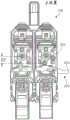
图2示出具有处于‘下’位置的第一挤压机的挤压机组件。Figure 2 shows the extruder assembly with the first extruder in the 'down' position.
图3示出具有处于‘上’位置的第一挤压机的挤压机组件。Figure 3 shows the extruder assembly with the first extruder in the 'up' position.
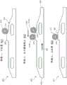
图4示出在多个位置与从动件接合的凸轮,以表示将挤压机组件的挤压机从‘下’位置移动到‘上’位置。Figure 4 shows the cam engaging the follower in various positions to represent moving the extruder of the extruder assembly from a 'down' position to an 'up' position.
图5示出在多个位置与从动件接合的凸轮,以表示将挤压机组件的挤压机从‘上’位置移动到‘下’位置。Figure 5 shows the cam engaging the follower in various positions to represent moving the extruder of the extruder assembly from an 'up' position to a 'down' position.
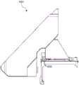
图6示出包括支承件的挤压机组件。Figure 6 shows the extruder assembly including the support.
图7示出与从动件接合的支承件。Figure 7 shows the support engaged with the follower.
图8示出与从动件接合的支承件的细节。Figure 8 shows details of the support engaging the follower.
图9示出处于‘上’位置的挤压机的侧视图。Figure 9 shows a side view of the extruder in the 'up' position.
图10示出处于‘下’位置的挤压机的侧视图。Figure 10 shows a side view of the extruder in the 'down' position.
图11是在具有多个挤压机的挤压机组件中用于改变挤压机的z轴位置的方法的流程图。11 is a flowchart of a method for changing the z-axis position of an extruder in an extruder assembly having multiple extruders.
图12示出具有处于‘下’位置的第一挤压机的挤压机组件。Figure 12 shows the extruder assembly with the first extruder in the 'down' position.
图13示出具有处于‘上’位置的第一挤压机的挤压机组件。Figure 13 shows the extruder assembly with the first extruder in the 'up' position.
图14是用于三维打印机的挤压机的示意图。Fig. 14 is a schematic diagram of an extruder used in a three-dimensional printer.
图15是用于三维打印机的挤压机的示意图。Fig. 15 is a schematic diagram of an extruder used in a three-dimensional printer.
图16是用于三维打印机的挤压机的热管理方法的流程图。16 is a flowchart of a thermal management method for an extruder of a three-dimensional printer.
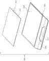
图17示出用于三维打印机的构建板。Figure 17 shows a build plate for a three-dimensional printer.
图18示出用于三维打印机的构建板的分解视图。Figure 18 shows an exploded view of a build plate for a three-dimensional printer.
图19示出其上设置有打印物体的构建板。Figure 19 shows a build plate with printed objects disposed thereon.
图20示出图19的构建板,其中从其移除打印物体。Figure 20 shows the build plate of Figure 19 with a printed object removed therefrom.
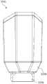
图21示出三维打印机的构建板系统。Figure 21 shows a build plate system for a three-dimensional printer.
图22是构建板系统的表示的横截面视图。Figure 22 is a cross-sectional view of a representation of the build plate system.
图23示出构建板系统的横截面视图。Figure 23 shows a cross-sectional view of the build plate system.
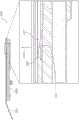
图24示出用于在构建板系统中联接构建板和骨架结构的机械特征。Figure 24 shows the mechanical features used to couple the build plates and the skeleton structure in the build plate system.
图25是用于在构建板系统中联接构建板和骨架结构的机械特征的横截面视图。25 is a cross-sectional view of mechanical features used to couple a build plate and a skeleton structure in a build plate system.
图26是使用三维打印机的构建板系统的方法的流程图。26 is a flowchart of a method of building a plate system using a three-dimensional printer.
图27示出具有挤压机盖的挤压机的透视图。Figure 27 shows a perspective view of an extruder with an extruder cover.
图28示出具有挤压机盖的挤压机的前视图。Figure 28 shows a front view of the extruder with the extruder cover.
图29示出具有挤压机盖的挤压机的热端的特写视图。Figure 29 shows a close-up view of the hot end of the extruder with the extruder cover.
图30是用于挤压机的盖的透视图。Figure 30 is a perspective view of a cover for an extruder.
图31是用于挤压机的盖的正视图。Figure 31 is a front view of a cover for an extruder.
图32是用于挤压机的盖的左侧视图。Figure 32 is a left side view of a cover for an extruder.
图33是用于挤压机的盖的右侧视图。Figure 33 is a right side view of a cover for an extruder.
图34是用于挤压机的盖的仰视图。Figure 34 is a bottom view of a cover for an extruder.
具体实施方式Detailed ways
现在将参考附图描述实施例。然而,前文可体现为许多不同的形式,且不应看作是限于本文所述的所示实施例。Embodiments will now be described with reference to the drawings. However, the foregoing may be embodied in many different forms and should not be construed as limited to the illustrated embodiments described herein.
本文提到的所有文献都在此通过引用以其整体并入本文中。以单数提到的物件应理解为包括复数个物件,且反之亦然,除非明确另外指出或从上下文清楚。连词旨在表示联接子句、句子、词语等的任何和所有分隔和连结组合,除非另外指出或从上下文清楚。因此,用语“或”应大体上理解为意指“和/或”等。All documents mentioned herein are hereby incorporated by reference in their entirety. Items referred to in the singular should be understood to include the plural and vice versa unless expressly stated otherwise or clear from the context. Unless otherwise indicated or clear from context, conjunctions are intended to mean any and all separating and joining combinations of joining clauses, sentences, words, etc. Thus, the term "or" should generally be read to mean "and/or" and the like.
本文的值的范围的叙述不旨在为限制性的,而改为独立地表示落入范围内的任何和所有值,除非本文另外指出,且此范围内的各个单独的值结合到说明书中如同其在此独立叙述。词语“约”、“大致”等在伴随数值时,看作是指出偏差,这是本领域的普通技术人员所认识到的,来令人满意地针对预期目的操作。类似地,当参考物理特性使用时,诸如“大致”或“基本”之类的近似词应理解为考虑偏差范围,本领域的普通技术人员应理解,该偏差范围可针对对应的用途、功能、目的等令人满意地操作。值和/或数值的范围在此仅提供为示例,且不会构成所述实施例的范围的限制。在提供值的范围的情况下,除非有相反的明确说明,否则它们还旨在包括该范围内的每个值,就好像分别阐述的那样。本文提供的任何和所有示例或示例性语言(“例如”、“诸如”等)的使用仅旨在更好地描述实施例,且并未提出对实施例的范围的限制。说明书中的语言将不看作是指出任何未提出的元件是实施例的实施中不可或缺的。The recitation of ranges of values herein is not intended to be limiting, but instead independently represents any and all values falling within the range, unless otherwise indicated herein, and each individual value within such range is incorporated into the specification as if It is described independently here. The words "about," "approximately," etc., when accompanying a numerical value, are deemed to indicate deviations that would be recognized by those of ordinary skill in the art to operate satisfactorily for the intended purpose. Similarly, when used with reference to physical properties, approximate words such as "approximately" or "substantially" should be understood as considering the range of deviation, and those of ordinary skill in the art will understand that the range of deviation may be specific to the corresponding use, function, Operate satisfactorily for purposes, etc. Values and/or ranges of values are provided herein as examples only, and do not constitute limitations on the scope of the embodiments. Where a range of values is provided, unless expressly stated to the contrary, they are also intended to include every value within that range, as if individually stated. The use of any and all examples, or exemplary language ("such as", "such as", etc.) provided herein is intended merely to better describe the embodiments and does not pose a limitation on the scope of the embodiments. No language in the specification should be construed as indicating that any non-recited element is essential to the practice of the embodiment.
在以下描述中,要理解,诸如“第一”、“第二”、“顶部”、“底部”、“上”、“下”等的用语是方便词语,且不看作是限制性用语,除非特别相反陈述。In the following description, it is to be understood that terms such as "first", "second", "top", "bottom", "upper", "lower", etc. are words of convenience and are not to be regarded as limiting terms, unless specifically stated to the contrary.
本文描述用于三维打印的改进的装置、系统和方法,如涉及挤压机和挤压技术、用于三维打印机的挤压机的热管理、用于三维打印机的构建板,以及用于三维打印机的挤压机的盖的改进。This article describes improved devices, systems, and methods for 3D printing, such as those related to extruders and extrusion technology, thermal management of extruders for 3D printers, build plates for 3D printers, and Improvements to the cover of the extruder.
以下说明着重介绍使用熔融沉积建模或类似技术的三维打印机,其中材料珠以二维图案的层状序列作为“路线”或“路径”挤压,以由数字模型形成三维物体。然而,将理解,本领域中已知多种增材制造技术,包括但不限于多喷射打印、立体光刻、数字光处理器(“DLP”)三维打印、选择性激光烧结等。这样的技术可受益于下面描述的系统和方法,且所有这样的打印技术旨在落入本公开的范围内,且落入诸如“打印机”、“三维打印机”、“制造系统”等的用语的范围内,除非明确提供更特定的含义或从上下文中可清楚。The following description focuses on 3D printers using fused deposition modeling or similar techniques, in which beads of material are extruded in a layered sequence of 2D patterns as "routes" or "paths" to form a 3D object from a digital model. However, it will be appreciated that a variety of additive manufacturing techniques are known in the art, including but not limited to multi-jet printing, stereolithography, digital light processor ("DLP") three-dimensional printing, selective laser sintering, and the like. Such technologies may benefit from the systems and methods described below, and all such printing technologies are intended to fall within the scope of this disclosure and within the scope of terms such as "printer," "three-dimensional printer," "manufacturing system," etc. unless a more specific meaning is explicitly provided or is clear from the context.
图1是三维打印机的框图。大体上,打印机100可包括与构建平台102(在本文中也可另外称为“构建板”)、传送机104、挤压机106、xyz定位组件108和控制器110,它们在打印机100的工作容积114内彼此协作,以由构建材料115制造物体112。Figure 1 is a block diagram of a 3D printer. In general,
构建平台102可包括刚性且基本平的表面116。表面116可支承传送机104以提供固定的、尺寸和位置稳定的平台,在该平台上构建物体112。
构建平台102可包括热元件130,该热元件通过一个或多个主动装置132(如热电加热和/或冷却装置)(例如,将电流转换为热的电阻元件、可产生加热或冷却效果的珀尔帖效应装置,及其组合)来控制构建平台102的温度。因此,热元件130可为向构建平台102提供主动加热的加热器、向构建平台102提供主动冷却的冷却元件,或这些的组合。加热器130可与控制器110以通信关系联接,使得控制器110可控制由加热器130施加到构建平台102的表面116或从构建平台的表面去除的热量。因此,例如,热元件130可包括定位在构建平台102内或附近的主动冷却元件,以可控制地冷却构建平台102。The
将理解,可另外或备选地采用多种其它技术来控制构建平台102的温度。例如,构建平台102可使用在其内部的气体冷却或气体加热装置,如真空室,其可根据需要快速加压以加热构建平台102或腾空以冷却构建平台102。作为另一个非排他性示例,可在构建过程之前,之中和/或之后将加热或冷却的气体流直接施加到构建平台102。It will be appreciated that a variety of other techniques may additionally or alternatively be employed to control the temperature of the
传送机104可包括片118,该片118在通过工作容积114的路径120中移动。在工作容积114内,路径120可沿构建平台102的表面116穿过——即,直接放置在表面116上或由表面116支承——使得构建平台102可提供刚性的,位置稳定的工作表面以进行构建。将理解的是,尽管路径120描绘为单向箭头,但是路径120可为多向的。例如,传送机104可在两个相对的方向中的任何一个上移动通过工作容积114。还应理解,路径120可各种方式中的任一种弯曲,如通过在构建平台102的下方和周围,在辊上方和/或下方,或在围绕片118的输送和收紧卷轴循环。因此,尽管路径120在整个工作容积114中可为大体(但不一定)一致的,但传送机104可在适合于将完成的物品从工作容积114中移出的任何方向上移动。传送机104可另外或备选地包括联接到控制器110以控制片118沿路径120的移动的马达或其它类似的驱动机构(未示出)。各种驱动机构在下面进一步详细描述。The
大体上,片118可由诸如网状材料、聚酰胺、聚对苯二甲酸乙二酯(可从DuPontTeijin Films USA(Chester, VA),以双轴形式以商品名以MYLAR®购得),聚酰亚胺膜(可从DuPont(Wilmington, DE)以KAPTON®购得),或任何其它适当强度的聚合物或其它材料。片118可具有大于约千分之三英寸(约0.0762mm)且小于约千分之七英寸(约0.1778mm)的厚度,或允许片118遵循传送机104的路径120的任何其它厚度。例如,在具有足够强的材料的情况下,片118的厚度可大于约千分之一英寸且小于约千分之三英寸。片118可进一步或改为包括通过柔性链节连结的刚性材料的区段。In general,
可处理片118的工作表面(例如,在工作容积114内的片118的顶表面上的区域)以辅助将构建材料115粘附到片118和/或有助于从片118上去除完成的物体。例如,工作表面可磨蚀或有其它纹理(例如,具有凹槽、突起等),以改善工作表面与构建材料115之间的粘附。The working surface of the sheet 118 (e.g., the area on the top surface of the
作为本文所述的构建过程的一部分,可在片118的工作表面上使用各种化学处理。例如,化学处理可包括沉积可通过使用水、溶剂等从传送机104化学去除的材料。通过溶解在物体112的完成实例与传送机104之间的化学处理层,这可促进将物体112的完成实例与传送机分开。化学处理可包括沉积诸如蜡、温和粘合剂之类的容易与传送机104分开的材料。化学处理可包括可剥离表面,例如粘合剂,该粘合剂在制造物体112之前喷涂到传送机104上。Various chemical treatments may be used on the working surface of
在一方面,传送机104可包括一次性的一次使用的材料的片,该材料从分配器供给并在每次连续构建中消耗。In one aspect, the
在一方面,传送机104可包括多个不同的工作区域,这些工作区域具有适用于构建材料115或过程的不同组成的不同表面处理。例如,不同的区域可具有不同的纹理(例如,光滑、磨蚀、开槽等)。另外或备选地,不同的区域可由不同的材料形成。此外,或替代地,不同的区域可具有或接受不同的化学处理。因此,应认识到,通过根据需要或期望选择各种工作区域,可在各种不同的建造过程中使用传送机104的单个实例。In one aspect, the
挤压机106可限定第一孔口121、第二孔口123以及将第一孔口121联接到第二孔口123的室122。构建材料115可例如包括丙烯腈丁二烯苯乙烯(“ABS”)、高密度聚乙烯(“HDPL”)、聚乳酸或任何其它合适的塑料、热塑性塑料或可有用地挤压而形成一个三维物体的其它材料中的一种或多种。挤压机106可包括限定出出口端口的挤压尖端124,该出口端口具有圆形、椭圆形、开槽形或其它横截面轮廓,其以期望的横截面形状挤压构建材料。
挤压机106可包括加热器126,以使室122内的构建材料115(例如,热塑性材料)熔融,以通过挤压尖端124的第二孔口123以熔融形式挤压。尽管为了清楚起见在图1中以方框形式表示,但是应理解,加热器126可包括例如缠绕在室122周围的电阻丝线圈、带有电阻元件通过施加电流来加热室122的一个或多个加热块、感应加热器,或适于在室122内产生热量以熔化构建材料115以用于挤压的加热器的任何其它布置。挤压机106还可包括或改为包括马达128,以在从第一孔口121朝向第二孔口123的方向上推动构建材料115穿过室122。
在大体的操作中(并且通过举例而非限制的方式),构建材料115最初可为诸如细丝形式的ABS塑料的形式,其可经由第一孔口121由马达128馈送到室122中,通过加热器126在室122中熔化,且经由第二孔口123从室122中挤压。通过控制工艺参数(例如,马达128的速率或加热器126的温度中的一个或多个),构建材料115可在受控的体积速率下从第二孔口123挤压。将理解的是,可采用多种技术以受控的体积速率输送构建材料115,其可取决于材料115的组成、期望的体积速率以及任何其它因素。所有可能适合于输送构建材料115以制造三维物体112的此类技术旨在落入本公开的范围内。其它技术可用于三维打印,包括使用可固化构建材料115的组成和/或粘度足以在挤压后保持形状的构建材料115的组成的基于挤压的技术。In general operation (and by way of example and not limitation),
xyz定位组件108大体上可移动以将挤压机106的第二孔口123三维地定位在工作容积114中。因此,例如,通过控制构建材料115的体积输送速率和第二孔口123的x、y、z位置,可通过将构建材料115的连续层以二维图案(例如,从计算机模型的横截面或物体112的其它计算机化表示中得出的二维图案)沉积来三维地制造物体112。xyz定位组件108可例如包括多个步进马达109(例如,可独立操作)以控制挤压机106且因此第二孔口123在工作容积114内沿x轴、y轴和z轴中的每个的位置。更一般地,xyz定位组件108可包括但不限于步进马达、编码DC马达、齿轮、带、带轮、蜗轮、蜗杆、螺纹等的各种组合。适合于将挤压机106的第二孔口123可控制地定位在工作容积114内的任何这样的布置可适于与本文所述的打印机100一起使用。The
通过举例而非限制,传送机104可在由传送机104的片118限定的平面内xy定位,而挤压机106可沿z轴相对于传送机104独立地移动。另外或备选地,传送机104可为x、y和z可定位的,且挤压机106可为固定的。此外,或替代地,在传送机104相对于工作容积114保持固定的同时,挤压机106可为x、y和z可定位的。在又一示例中,传送机104可通过片118的移动来控制在一条轴线(例如,y轴)上的移动,而挤压机106在z轴以及在由片118限定的平面中的一条轴线上移动。因此,在某些实例中,传送机104可附接到xyz定位组件108的x轴平台(控制沿x轴的移动)、y轴平台(控制沿y轴的移动)和z轴平台(控制沿z轴的移动)中的至少一个并随其移动。更一般地,xyz定位组件108可包括可由控制器110控制以定位本文所述的挤压机106的马达和其它硬件的任何布置。还更一般地,虽然x、y、z坐标系可能便于在三个维度内定位,但是也可或替代地采用任何其它坐标系或坐标系的组合,如根据圆柱坐标或球坐标中的一个或多个进行操作的位置控制器和组件。By way of example and not limitation, the
控制器110可与构建平台102、传送机104、xyz定位组件108和打印机100的其它各种构件以通信关系电联接。大体上,控制器110可操作以控制打印机100的构件,如构建平台102、传送机104、xyz定位组件108以及本文所述的打印机100的任何其它构件,以由构建材料115制造物体112。控制器110可包括适合于控制本文描述的打印机100的各种构件的软件和/或处理电路的任何组合,包括但不限于微处理器、微控制器、专用集成电路、可编程门阵列以及任何其它数字和/或模拟构件以及前述的组合,以及用于收发控制信号、驱动信号、功率信号、传感器信号等的输入和输出。在一方面,控制器110可包括具有足够算力的微处理器或其它处理电路,以提供相关功能,如执行操作系统,提供图形用户界面(例如,提供给联接到控制器110或打印机100的显示器),将三维模型转换为工具指令,以及通过以下所述的网络接口136操作网络服务器或以其它方式托管远程用户和/或活动。
可将多种额外的传感器有用地结合到上述打印机100中。这些一般描绘为图1中的传感器134,为此,与打印机100的其它元件的定位以及机械/电气互连将取决于传感器134的类型和目的,且本领域的普通技术人员将容易理解和认识它们。传感器134可包括定位成感测构建平台102的表面的温度的温度传感器。例如,这可包括嵌入在构建平台102的表面内或附在构建平台的表面下方的热敏电阻。这也可或替代地包括指向构建平台102的表面116或传送机104的材料片118的红外检测器。可有用地并入打印机100中作为传感器134的其它传感器包括但不限于热传感器、体积流率传感器、重量传感器、声音传感器和光传感器。以下通过举例而非限制的方式提供某些更特定的示例。A variety of additional sensors may be usefully incorporated into the
传感器134可在传送机104上的预定位置检测物体112的存在(或不存在)。这可包括处于光束断开配置中的光学检测器,以感测物体112在诸如传送机104的端部的位置处的存在。这也可或替代地包括成像装置和图像处理电路,以捕获工作容积114的图像并分析该图像以评估物体112的位置。该传感器134可例如用于确保在工作表面(例如,构建平台102的表面116)上的那个位置开始新构建之前,将物体112从传送机104移除。因此,传感器134可用于确定是否存在不应该存在的物体,或用于检测何时不存在物体,或其组合。控制器110可使用来自该传感器134的反馈来发出处理中断或以其它方式控制打印机100的操作。
传感器134可检测传送机104沿路径的位置。该信息可例如从驱动传送机104的马达中的编码器获得,或使用任何其它合适的技术获得,例如视觉传感器和片118上的对应基准(例如,可见图案、孔或具有不透明、镜面、透明的或其它可检测的标记的区域)。
传感器134可包括加热器(例如,辐射加热器或强制热空气),以加热工作容积114以在整个构建过程中将物体112保持在固定的升高的温度。传感器134还可或替代地包括冷却元件,以在整个构建过程中将物体112保持在预定的低于环境的温度。应认识到,包括在传感器134中的加热器可代替或除了热元件130。
传感器134还可或替代地包括至少一个摄像机。摄像机大体上可捕获工作容积114、物体112或与打印机100相关联的任何其它硬件的图像。摄像机可通过网络接口136提供远程视频馈送。在此类实例中,馈送可通过例如由远程硬件维护的用户界面来供远程用户使用,或,进一步地或替代地,该馈送可能在由三维打印机100托管的网络服务器提供的网页中可用。因此,在某些实施方式中,存在一种用户界面,该用户界面适于通过用户界面将来自三维打印机的至少一个摄像机的视频馈送呈现给远程用户。
传感器134还可或替代地包括更复杂的感测和处理系统或子系统,诸如使用光学技术(例如,立体成像或来自运动成像的形状)的三维扫描仪、结构化光技术或可从工作容积114提取三维信息的任何其它合适的传感和处理硬件。在一些实例中,传感器134可包括机器视觉系统,该机器视觉系统捕获图像并分析图像内容以获得关于工作状态、工作容积114或其中的物体112的信息。机器视觉系统可支持三维打印机100的各种基于图像的自动检查、过程控制和/或机器人引导功能,包括但不限于通过/失败决定、错误检测(以及对应的声音或视觉警报)、形状检测、位置检测、方向检测、避免碰撞及其组合。
打印机100可包括其它硬件135,其它硬件可为例如包括以下任何一个或多个的输入装置:键盘、触摸板、鼠标、开关、拨盘、按钮和运动传感器。另外或备选地,其它硬件135可为例如包括以下任何一个或多个的输出装置:显示器、扬声器或其它音频换能器以及发光二极管。其它硬件135也可或替代地包括各种电缆连接和/或硬件适配器,用于例如连接到外部计算机、外部硬件、外部仪器数据采集系统及其组合。The
打印机100可包括网络接口136或与网络接口成通信关系连接。网络接口136可包括适合于通过数据网络以通信关系将控制器110和打印机100的其它构件联接到远程计算机的硬件和软件的任何组合。作为示例而非限制,这可包括用于根据IEEE 802.11标准(或其任何变型)或任何其它短程或长程无线联网构件进行操作的有线或无线以太网连接的电子设备。这可包括诸如蓝牙或红外收发器之类的用于短程数据通信的硬件,其可用来联接到局域网中,该局域网又联接到诸如因特网的数据网络上。这也可或替代地包括用于WiMAX连接或蜂窝网络连接的硬件/软件(例如使用CDMA、GSM、LTE或任何其它合适的协议或协议的组合)。控制器110可配置成控制打印机100参与网络接口136所连接的任何网络,例如通过自主地连接到网络以检索可打印的内容,或响应于对状态或可用性的远程请求。The
挤压机高度切换Extruder height switch
现在将论述对三维打印的特定改进,例如,使用上面参考图1所述的三维打印机。一个这样的改进可包括用于改变多挤压机组件中的一个或多个挤压机的z轴位置的系统,且另一个这样的改进可包括机械阻尼,该机械阻尼通过在可移动挤压机降低到进行打印的位置时逐渐转移竖直负载来减轻噪声和振动。以该方式,本教导大体可包括凸轮,该凸轮用作具有多个挤压机的挤压机组件的“拨动”。特别地,挤压机组件可包括两侧拨杆(例如,用于两个挤压机),以及用于可通过这样的两侧拨杆产生的噪声和振动的阻尼。Specific improvements to three-dimensional printing will now be discussed, for example, using the three-dimensional printer described above with reference to FIG. 1 . One such improvement may include a system for changing the z-axis position of one or more extruders in a multi-extruder assembly, and another such improvement may include mechanical damping by Reduce noise and vibration by gradually shifting the vertical load as the machine is lowered into the printing position. In this manner, the present teachings generally may include a cam that acts as a "dial" for an extruder assembly having multiple extruders. In particular, the extruder assembly may include a side ram (eg, for both extruders), and damping for noise and vibration that may be generated by such a ram.
图2示出第一挤压机处于‘下’位置的挤压机组件,而图3示出第一挤压机处于‘上’位置的挤压机组件。挤压机组件200可包括多个挤压机——例如第一挤压机201和第二挤压机202——其中这些单独的挤压机中的任何一个可包括上述图1的挤压机106的任何特征。换句话说,除非另外指定或从上下文中弄清楚,否则应该将挤压机组件200理解为与以上关于图1论述的挤压机106可互换。Figure 2 shows the extruder assembly with the first extruder in the 'down' position, while Figure 3 shows the extruder assembly with the first extruder in the 'up' position. The
大体上,具有带有x轴(它将横穿出入图1和2中的页面)、y轴204和z轴205的构建容积的三维打印机可具有挤压机组件200,其可包括多个挤压机。将理解的是,除非明确地指出相反或从上下文中可清楚地看出,否则当涉及挤压机组件200或它的构件沿y轴204的移动时,这还可或替代地包括沿x轴的移动。即,大体上,本教导可包括沿x轴和y轴204中的一个或多个移动的挤压机组件200,以沿z轴205移动一个挤压机。In general, a three-dimensional printer having a build volume with an x-axis (which will traverse into and out of the page in FIGS. 1 and 2 ), a y-
挤压机组件200(或更一般地,三维打印机)可包括多挤压机,该多挤压机包括第一挤压机201和第二挤压机202、多个从动件(例如,第一从动件210和第二从动件212)、凸轮220、支承件和联接到支承件的阻尼器(尽管在图2和图3中未示出,但是支承件670和阻尼器680在例如图6和图7所示)。Extruder assembly 200 (or, more generally, a 3D printer) may include a multi-extruder comprising a
返回至图2和图3,第一挤压机201和第二挤压机202中的一个或多个可相对于保持挤压机组件200的机架或滑架250沿z轴205移动(例如,其中滑架250可通过诸如上述的xyz定位组件移动)。例如,第一挤压机201和第二挤压机202中的每个可为可移动的,或这些挤压机中的一个可固定,而另一个可移动。举例来说,在一个实施方式中,第一挤压机201可移动地联接到三维打印机,以允许第一挤压机201在z轴205的方向上独立于第二挤压机202改变位置,而第二挤压机202保持在固定的z轴位置。以该方式,一个或多个挤压机可相对于另一个(其它)沿z轴205独立地移动,或当沿z轴205移动时,这些挤压机可彼此协作。Returning to FIGS. 2 and 3 , one or more of the
第一挤压机201可限定穿过第一挤压机201的第一挤压孔口208的第一挤压路径206,其中第一挤压路径206的至少一部分沿z轴205设置。类似地,第二挤压机202可限定穿过第二挤压机202的第二挤压孔口209的第二挤压路径207,其中第二挤压路径207的至少一部分沿z轴205设置。The
第一挤压机201可包括或以其它方式联接到一个或多个从动件——例如,第一从动件210和第二从动件212。从动件可包括轴承、轮等,其中从动件可绕轴线(例如,沿x轴对准的轴线)自由旋转,但从动件的轴线相对于第一挤压机201固定。大体上,从动件可包括定向成允许沿x轴或y轴604相对低摩擦移动的承载表面。即,从动件可在结构上构造为旋转并沿诸如凸轮220的工作表面222的表面跟随。
第一从动件210和第二从动件212中的每个相对于第一挤压机201的位置可为固定的。即,因为从动件可包括轴承或轮,所以从动件可旋转,而机械上不鼓励或防止相对于挤压机的其它移动。以该方式,如果第一从动件210和第二从动件212中的一个或多个移动(例如,沿z轴205),则第一挤压机201(或保持第一挤压机201的滑架250的一部分)可类似地移动。更简洁地说,在某些实施方式中,如果从动件沿z轴205受到至少预定的力,则从动件和第一挤压机201都将沿z轴205移动。The position of each of the
因此,第一从动件210可在结构上构造为调整第一挤压机201的z轴位置。即,当第一从动件210升高时(例如,通过凸轮220的工作表面222),第一挤压机201可类似地升高,反之亦然。Accordingly, the
大体上,第二从动件212可在结构上构造为抑制第一挤压机201从非打印高度沿z轴205降低到打印高度。即,由于所使用的材料(例如,金属)和挤压机的重量,沿z轴205将第一挤压机201从非打印高度降低到打印高度可能导致不想要的噪声或振动。为了减轻这种情况,第二从动件212可定位并在结构上构造为沿另一个表面(例如,阻尼器的表面)移动,该另一个表面可为倾斜的或以其它方式成形以承受第一挤压机201的z轴负载的至少一部分,且当从非打印高度沿z轴205过渡到打印高度时,或以其它方式使第一从动件210从凸轮220的工作表面222分离时,将第一负载逐渐转移到不同的z轴位置。In general, the
凸轮220可包括延伸穿过第一挤压机201和第二挤压机202中的一个或多个的伸长部件(例如,凸轮220可延伸穿过挤压机组件200中的每个挤压机)。另外,或替代地,凸轮220可延伸穿过滑架250并与滑架联接,滑架保持第一挤压机201和第二挤压机202中的一个或多个。凸轮220可相对于第一挤压机201和第二挤压机202中的一个或多个移动(例如,可滑动)。即,凸轮220可具有可相对于第一挤压机201移动的工作表面222,例如,其中工作表面222是形成凸轮220的伸长本体的顶表面。工作表面222可定形为将凸轮220沿x轴或y轴205中的一个或多个的第一移动转换为第一从动件210沿z轴205的第二移动。以该方式,当工作表面222相对于第一挤压机201移动以使第一从动件210沿z轴205升高时,第一从动件210可沿凸轮220的工作表面222移动。并且因为第一从动件210的轴线可相对于第一挤压机201固定,所以第一从动件210沿z轴205的移动可类似地使第一挤压机201沿z轴205移动。
因此,凸轮220可用作挤压机组件200的拨杆,具有调整挤压机组件的一个或多个挤压机的z轴高度的能力——例如,在用于在三维打印中沉积构建材料的打印高度与挤压机不在三维打印中沉积构建材料的非打印高度之间。凸轮220的工作表面222可定形为当凸轮220沿y轴204(或与z轴205相交的另一轴线)在第一方向上移动时,经由第一从动件210沿z轴205提升第一挤压机201(或第二挤压机202)。Thus, the
如上所述,凸轮220可延伸穿过第一挤压机201和第二挤压机202中的每个,使得凸轮220的第一端223和第二端224中的每个暴露于多挤压机式挤压机组件200的外部。以该方式,可从多挤压机组件200的外部接触凸轮220的第一端223和第二端224中的任一个,以相对于多挤压机组件200在任一方向上竖直地移动凸轮220。在某些实施方式中,凸轮220与滑动件226等(例如,一个或多个轴承)连通,这有助于凸轮220相对于挤压机组件200的挤压机的滑动。As described above, the
在某些实施方式中,诸如弹簧的偏压部件230可联接到第一挤压机201和第二挤压机202中的一个或多个,或联接到接合至第一挤压机和第二挤压机的构件。偏压部件230可在结构上构造为沿z轴205朝向打印高度或非打印高度偏压第一挤压机201和第二挤压机202中的一个或多个,例如在没有其它力的情况下,如凸轮220的工作表面222对第一从动件210的力。例如,这可减轻单独挤压机的随着多挤压机组件200在使用期间在构建容积内移动的嘎嘎声。In certain embodiments, a biasing
挤压机组件200还可包括一个或多个驱动轮240。在某些实施方式中,单个驱动轮240可由第一挤压机201和第二挤压机202中的每个共用,以驱动穿过其中的构建材料(例如,丝)。为此,驱动轮240的位移(例如,沿z轴205)可与第一挤压机201和第二挤压机202之一交替地脱离或接合。在另一方面,驱动轮240可离合器接合或以其它方式机械地构造成:驱动轮240的顺时针旋转使一个挤压机前进,而驱动轮240的逆时针旋转使另一个挤压机前进。在诸如图2和图3所示的其它实施方式中,每个挤压机可包括其自身的驱动轮240。The
如上所述,凸轮220可与第一从动件210协同工作,以移动第一挤压机201的z轴位置。例如,且如上所述,图2示出第一挤压机201处于下位置的挤压机组件200,且图3示出第一挤压机201处于上位置的挤压机组件200,其中下位置是打印位置,而上位置是非打印位置。即,当第一挤压机201处于下位置时,其可定位为在三维打印操作中沉积构建材料,而第二挤压机202处于上位置(相对于第一挤压机20——如提到的,第二挤压机202可沿z轴205保持静止,而第一挤压机201向上和向下移动),同时不活动,例如在三维打印操作中不沉积构建材料时;并且当第一挤压机201处于上位置或非活动位置时,第二挤压机202可相对于第一挤压机201处于活动位置,以在三维打印操作中沉积构建材料。在某些实施方式中,仅一个挤压机能够在上位置和下位置之间移动,而另一个挤压机相对于滑架250保持固定在预定的z轴高度。在其它实施方式中,挤压机组件200中的每个挤压机都能够在上位置和下位置之间移动。例如,当一个挤压机移动时(例如,从上位置移动到下位置),另一个挤压机可沿z轴205在相反方向上自动移动(例如,从下位置到上位置),例如通过枢轴联接两个挤压机,该枢轴会强制执行交替的z轴移动,或通过控制或互连两个挤压机以实现相反的竖直运动。As described above, the
将理解的是,下位置和上位置之间的差异可相对小。例如,在某些实施方式中,用于沉积构建材料的挤压机的末端的上位置和下位置之间的z轴高度差在约1-2mm(例如约1.4mm)之间,或足够大垂直位移以避免在非活动挤压机的最低点和由活动挤压机沉积的构建材料的最高点之间发生干扰。图2和图3通过示出第一挤压机201中的第一从动件210的轴与第二挤压机202的驱动轮240之间的z轴高度的差异来表示该z轴高度差。即,图2中的距离D1示出在第一挤压机201处于下位置时第一挤压机201中的第一从动件210的轴之间的z轴高度差;并且图3中的距离D2示出当第一挤压机201处于上位置时第一挤压机201中的第一从动件210的轴之间的z轴高度差。特别地,D1可大于D2,其表示第一挤压机201的z轴位置位于远离在下位置的第二挤压机202的驱动轮240的位置(其可相对于滑架250具有固定的z轴位置)。在某些实施方式中,D1为约12.600mm,且D2为约11.194mm。然而,对于D1和D2,其它距离也是可能或替代地是可能的。It will be appreciated that the difference between the lower and upper positions may be relatively small. For example, in some embodiments, the difference in z-axis height between the upper and lower positions of the tip of the extruder for depositing the build material is between about 1-2 mm (e.g., about 1.4 mm), or sufficiently large Vertical displacement to avoid interference between the lowest point of the inactive extruder and the highest point of build material deposited by the active extruder. 2 and 3 represent this z-axis height difference by showing the difference in z-axis height between the shaft of the
图4示出与在多个位置的多个从动件啮合的凸轮,以表示将挤压机组件的挤压机从‘下’位置(或活动位置或打印高度)移动到‘上’位置(或非活动位置或非打印高度)。该图中所示的凸轮420和从动件410可与以上参考图2和图3论述的凸轮220和第一从动件210相同或相似。Figure 4 shows a cam engaging multiple followers in various positions to represent moving the extruder of the extruder assembly from the 'down' position (or active position or print height) to the 'up' position ( or non-active position or non-print height). The
返回到图4,如阶段一401所示,在挤压机的下位置,该挤压机包括从动件410或与之接合,从动件在结构上构造为沿凸轮420的工作表面422穿过,从动件410可设置在与工作表面422的台阶426相邻的位置上(而不是不在其上)(例如,设置在工作表面422的顶点处)。从动件410的位置可相对于挤压机固定,但是从动件410可在结构上构造为绕轴线411旋转——因此,轴线411的位置可相对于挤压机固定,其中从动件410的移动(除了从动件410的旋转之外)可引起挤压机的对应移动。Returning to FIG. 4 , as shown in stage one 401 , in the lower position of the extruder, the extruder includes or engages a
如阶段二402所示,当凸轮420在第一方向432上移动时,从动件410可沿凸轮420的工作表面422在第二方向434上从第一位置410a移动到第二位置410b。即,从动件410可沿工作表面422朝向凸轮420的第一端423并且远离凸轮420的第二端424移动。从动件410在第二方向434上的该移动可导致从动件410在第二方向434上朝向工作表面422的台阶426横穿工作表面422的斜面部分428。该移动可能导致从动件410(并且因此导致其固定接合的挤压机)的z轴位置发生变化,其中从动件410的z轴位置变化对应于在设置于台阶426下方的工作表面422的区域(例如,在斜面部分428上或下方的区域)与工作表面422的台阶426之间的z轴高度差。该z轴高度变化由阶段二402中所示的从动件410的第一位置410a和第二位置410b表示。As shown in stage two 402 , when the
阶段三403示出从动件410处于上位置。特别地,在阶段三403中,从动件410的z轴高度位置可在阶段一401中位于其z轴高度位置的上方,其表示从动件410(并且因此其固定地接合的挤压机)的z轴高度可在阶段一401所示的下位置和阶段三403所示的上位置之间变化。此外,在阶段三403中,在与从动件410接合的挤压机的上位置中,从动件410可设置在工作表面422的台阶426上的位置。在此位置,凸轮420在第二方向434上的移动可能导致从动件410返回到其在阶段一401中所示的位置。Stage three 403 shows the
还将提到的是,凸轮420可包括脊430或其它类似特征,以在台阶426上为从动件410提供双稳态位置。这可帮助防止凸轮420在将力施加到凸轮420的第二端424以有目的地使从动件410和相关联的挤压机降低到活动位置之前的使用期间沿相反方向漂移并释放从动件410。即,工作表面422可包括设置在斜面部分428上方的台阶426,以将挤压机支承于非活动非打印位置。工作表面422还可包括脊430,其高度大于台阶426。特别地,脊430可定位在台阶426和斜面部分428之间,以将挤压机双稳态地保持在非活动位置(例如,当如本文所述,当挤压机不与阻尼器接合时)。然而,尽管如阶段三403中所示对于保持从动件在台阶426上的位置是有用的,但是当行进至下位置时,包括脊430则可导致从动件410在脊430上“跳动”。此类跳动可导致不必要的噪声和振动,从而最终损坏挤压机组件或三维打印机的构件。因此,可有利地包括如本文其它各处所述的支承件和阻尼器中的一个或多个,以与这种挤压机组件一起使用,以尤其减轻这种不希望的噪声和振动。It will also be mentioned that the
图5示出在多个位置与从动件接合的凸轮,以表示将挤压机组件的挤压机从‘上’位置移动到‘下’位置。图5中的凸轮420可与上文参照图4所描述的凸轮相同,且因此对于这些附图大体使用相同的参考标记。更特别地,虽然图4表示从动件410从较低的z轴高度位置到较高的z轴高度位置的移动,图5示出相反的——即,从动件410从较高的z轴高度位置移动到较低的z轴高度位置。Figure 5 shows the cam engaging the follower in various positions to represent moving the extruder of the extruder assembly from an 'up' position to a 'down' position. The
图5的阶段三403与图4所示的阶段三403相同,其中从动件410设置在上位置,例如在凸轮420的工作表面422的顶点426上。如上文陈述的,且如由下面描述的阶段四404和阶段五405所表示的,凸轮420在第二方向434上的移动可导致从动件410返回到下位置。Stage three 403 of FIG. 5 is the same as stage three 403 shown in FIG. 4 , wherein the
如阶段四404所示,当凸轮420在第二方向434上移动时,从动件410可沿凸轮420的工作表面422在第一方向432上从第二位置410b移动到第一位置410a。即,从动件410可沿工作表面422朝向凸轮420的第二端424并且远离凸轮420的第一端423移动。从动件410在第一方向432上的该移动可导致从动件410在第一方向432上向下穿过工作表面422的斜面部分428,即离开并远离工作表面422的台阶426。As shown in stage four 404 , when the
阶段五405代表从动件410(并且因此其可固定地接合的挤压机)的下位置,其中阶段五405可与图4的阶段一401相同。Stage five 405 represents the lower position of the follower 410 (and thus the extruder it may fixedly engage), wherein stage five 405 may be the same as stage one 401 of FIG. 4 .
应理解,从动件410和与之接合的挤压机(或滑架)在图5中的这种向下移动可能是嘈杂的和/或可能引起不希望的振动。因此,本教导可包括减轻这种噪声和振动的特征。一个这样的特征可包括工作表面422自身的尺寸和形状。即,通过包括具有相对浅的斜率/斜度的斜面部分428(或另一类似特征),挤压机可逐渐降低到活动位置,且可减轻伴随的机械噪声和振动。下面描述减轻此类噪声和振动的额外或备选的特征。It should be appreciated that this downward movement of the
图6示出包括支承件的挤压机组件,且图7示出与从动件接合的支承件。特别地,这些图示出挤压机组件600的滑架650(其可与在此描述的任何挤压机组件相同或相似)、机架660和支承件670。图6可表示滑架650中的第一挤压机的上位置,而图7可表示第一挤压机设置在下位置之前的时刻。大体上,当沿一条或多条轴线移动挤压机组件600的挤压机时,支承件670和相应的阻尼器680可用于减轻噪声和/或振动。另外,或替代地,支承件670可与凸轮620结合使用以升高和降低挤压机组件600的挤压机。Figure 6 shows the extruder assembly including the bearing, and Figure 7 shows the bearing engaging the follower. In particular, these figures show carriage 650 (which may be the same or similar to any extruder assembly described herein),
滑架650可在结构上构造成保持或以其它方式与挤压机组件600的一个或多个挤压机联接——例如,图6和7中的示例性实施例的滑架650可在结构上构造成与两个挤压机联接。特别地,滑架650可包括一个或多个子滑架,每个子滑架在结构上构造成用于容纳或以其它方式联接到挤压机。例如,图6和7的滑架650包括第一子滑架651和第二子滑架652,其可在结构上构造成分别与第一挤压机和第二挤压机(诸如上文描述的第一挤压机和第二挤压机)接合。因此,滑架650可在结构上构造成在其中例如在由滑架650的结构限定的一个或多个腔654内接收一个或多个模块化挤压机。以该方式,第一挤压机可支承于滑架650上,其中第一挤压机限定第一挤压路径,且其中第一从动件610沿凸轮620的工作表面的移动改变第一挤压机的z轴位置。例如,凸轮620的工作表面可相对于第一挤压机沿x轴或y轴移动。除了第一挤压机之外,第二挤压机可支承于滑架650上,其中第二挤压机限定不同于第一挤压机的第一挤压路径的第二挤压路径。The
在某些实施方式中,如图6和7的实施例,滑架650可包括或另外联接到凸轮620、第一从动件610和第二从动件612。备选地,这些构件中的一个或多个可包括在一个或多个模块化挤压机上,这些挤压机构造成联接到滑架650或在滑架650内。无论如何,子机架和挤压机中的一个或两者可在结构上构造为与第一从动件610和第二从动件612中的一个或多个一起移动。因此,第一从动件610和第二从动件612中的一个或多个可相对于滑架650和/或联接到其的挤压机在位置上(但不是旋转地)固定。In certain embodiments, such as the embodiments of FIGS. 6 and 7 , the
滑架650(或其一部分,如第一子滑架651和第二子滑架652中的一个或多个)可枢转地连接到机架660或相对于机架枢转地设置。因此,当提升滑架650、挤压机或子滑架时(例如,经由第一从动件610通过其沿凸轮620的工作表面的移动),该构件可相对于机架旋转或以其它方式向上移动660。Carriage 650 (or a portion thereof, such as one or more of first sub-carriage 651 and second sub-carriage 652 ) is pivotally connected to or pivotally disposed relative to frame 660 . Thus, when the
机架660大体上可包括挤压机组件600在三维打印机内位于其上的结构。例如,机架660可连接到xyz定位组件或与xyz定位组件连通,以将挤压机组件600定位在三维打印机的构建容积内。大体上,机架660可包括引导表面662,挤压机组件600可在该引导表面上沿x轴和y轴中的一个或多个移动。例如,挤压机组件600可包括如本文所述的机架660和滑架650,其中机架660具有限定垂直于z轴的轴线的引导表面662,第一挤压机被支承于滑架650上(例如,在第一子滑架651中),且滑架650可沿机架660的引导表面662在沿垂直于z轴的轴线(例如x轴或y轴)的至少一个方向上移动。以该方式,且如图6和图7所示,阻尼器680或支承件670中的至少一个可沿垂直于z轴的轴线设置在固定位置中。
机架660还可包括支承件670或与支承件670接合。因此,支承件670可位于机架660上——例如,支承件670可固定在机架660上,且可通过挤压机组件沿与z轴相交的轴线(例如,x轴或y轴)的移动而与挤压机组件600接合。支承件670也可或替代地联接到三维打印机的侧面或三维打印机的另一构件。无论如何,支承件670可与凸轮620的端部接合以相对于滑架650移动凸轮620(例如,平移、拨动或滑动凸轮620)。The
如上所述,凸轮620可具有工作表面,工作表面可相对于挤压机组件600的至少一个挤压机移动,且定形为将凸轮620沿x轴或y轴的第一移动转换为第一从动件610沿z轴的第二移动。以该方式,随着工作表面相对于第一挤压机和第一子滑架651中的一个或多个移动以沿z轴升高第一从动件610,第一从动件610可沿凸轮620的工作表面移动。支承件670可与凸轮620接合,以使凸轮620的第一移动反向且沿z轴降低与第一从动件610相邻的工作表面。因此,凸轮620的工作表面可响应于同支承件670与凸轮620的接合相关联的力来相对于第一挤压机和第一子滑架651中的一个或多个移动。As described above, the
阻尼器680可联接到支承件670。阻尼器680可与第一挤压机和第一子滑架651中的一个或多个接合,以从其接收z轴负载,且随着支承件670降低与第一从动件610邻近的凸轮620的工作表面的高度,使第一从动件610与凸轮620的工作表面分离。更特别地,阻尼器680可与第二从动件612接合。The
在某些实施方式中,阻尼器680可包括沿x轴或y轴中的一个或多个从支承件670悬伸的臂。以该方式,支承件670、阻尼器680和凸轮620可一起工作以调整滑架650中的挤压机在机架660上的z轴位置。例如,凸轮620可为线性凸轮,其中凸轮620的工作表面在由z轴和诸如y轴的相交(例如,垂直)轴线限定的平面上具有第一二维轮廓。阻尼器680的臂可在由z轴和y轴限定的平面中具有第二二维轮廓,其中阻尼器680的臂可与第二从动件612接合,以随着挤压机的z轴负载支承于臂上而使第二从动件612沿臂的第二二维轮廓。如图6和图7中表示的,凸轮620的工作表面的第一二维轮廓可与阻尼器680的臂的第二二维轮廓不同。然而,尽管不同,但是这些尺寸轮廓的尺寸和形状可设定为彼此协同工作以减轻在调整挤压机组件600中的挤压机的z轴位置时的噪声或振动。例如,阻尼器680的接触表面682可包括倾斜度,以随着滑架从支承件670移开而逐渐降低第二从动件612。In certain embodiments, the
如本文所述,第二从动件612可设置在第一挤压机和第一子滑架651中的一个或多个上或之内。如图7中最佳所示,第二从动件612可沿阻尼器680移动,其中阻尼器680可经由第二从动件612接收来自第一挤压机和第一子滑架651中的一个或多个的z轴负载。为此,阻尼器680可包括用于第二从动件612的接触表面682,其中接触表面682定形为取决于机架660的构型,在挤压机组件600沿x轴或y轴移动远离支承件670时使第一挤压机和第一子滑架651中的一个或多个沿z轴平稳地降低到工作位置中。As described herein, the
如上所述,第一从动件610和第二从动件612可设置在滑架650和/或挤压机组件600的挤压机上,其中第一从动件610和第二从动件612中的一个或多个的z轴移动可类似地向滑架650(或其一部分,如子滑架)和/或挤压机组件600的挤压机提供z轴移动。大体上,第一从动件610可沿凸轮620的工作表面移动(例如,与凸轮620的工作表面滚动接触),且第二从动件612可沿阻尼器680移动(例如,与阻尼器680或支承件670滚动接触)。为此,第一从动件610和第二从动件612可至少沿z轴彼此间隔开。第一从动件610和第二从动件612也可或替代地沿x轴和y轴中的一个或多个彼此间隔开。As described above, the
因此,大体上如图6和7所示,支承件670可具有第一表面671(例如侧表面),随着滑架650沿第二方向602接近支承件670,该第一表面接触凸轮620以使凸轮620沿y轴(或x轴)在第一方向601上移动。支承件670还可包括阻尼器680,或以其它方式与阻尼器一起工作,该阻尼器具有接触表面682,该接触表面随着滑架650通过沿第二方向602行进来接近支承件670而接收挤压机(或构造为与挤压机接合的子机架)的z轴负载。Accordingly, as generally shown in FIGS. 6 and 7 , the
进一步如图7所示,支承件670的第一表面671与凸轮620接合以引起凸轮620的工作表面在第一方向601上的移动可能最终使第一从动件610与凸轮620的工作表面完全脱离。以该方式,在这样的实施例中,在不存在阻尼器680的情况下,第一挤压机将相对突然下降,这可能引起不想要的噪声或振动。然而,阻尼器680可通过与第二从动件612接合而接收来自第一挤压机的z轴负载。以该方式,随着滑架650继续在第一方向601上移动远离支承件670,第一挤压机可逐渐降低,特别是在阻尼器680的接触表面682包括斜坡或倾斜表面以提供第二从动件612(并且因此挤压机或与其接合的子滑架)的逐渐z轴位置改变。As further shown in FIG. 7 , the
图8示出与从动件接合的支承件的细节。特别地,该图示出与在箭头801的方向从第一位置812a向下移动到第二位置812b的第二从动件接合的支承件870(其可与以上参照图6和图7示出和描述的支承件670相同或相似)的细节。更特别地,支承件670可包括阻尼器880,该阻尼器的接触表面882的尺寸和形状(例如,在与z轴相交的平面(诸如由x轴和y轴限定的平面)中包括二维轮廓)设定成将第二从动件的z轴位置从第一位置812a逐渐改为第二位置812b,且然后随着第二从动件移出阻尼器的竖直支承极限而完全释放第二从动件880。为此,接触表面882的二维轮廓可包括一个或多个斜坡部分。特别地,接触表面882的倾斜表面可包括成角度或成斜坡的第一表面884,以随着多个挤压机朝向支承件870移动而接收来自挤压机的负载,以及成角度或成斜坡的第二表面886,以在多个挤压机移动远离支承件870时使挤压机平稳且连续地降低到工作位置中。以该方式,第二从动件可相对渐进的方式从与阻尼器880的接触表面882的接触中释放,这可帮助减轻联接到第二从动件的挤压机或子滑架的z轴位置的相关变化的噪声或振动。Figure 8 shows details of the support engaging the follower. In particular, the figure shows a
图9示出处于‘上’位置的挤压机的侧视图,且图10示出处于‘下’位置的挤压机的侧视图。这些图表示挤压机900(或与挤压机联接的滑架或子滑架)如何可枢转以改变其z轴位置。如图9所示,例如,当使用本文描述的技术将挤压机900(以及因此挤压机部分904)提升到非活动位置时,在挤压机部分904与结构906之间可能存在间隙902。另外,如图10所示,处于活动或下位置的挤压机900可接触另一结构906,该另一结构可为滑架、子滑架、框架或另一构件。如果这种接触以相对急速和突然的方式开始,则可能在三维打印机中引起不希望的噪声和/或振动。如果由于挤压机的向下移动而接触的构件分别由金属或类似材料制成,这可进一步放大。因此,本文所述的阻尼技术对于减轻这种不希望的噪声或振动可能是有利的。Figure 9 shows a side view of the extruder in the 'up' position and Figure 10 shows a side view of the extruder in the 'down' position. These figures show how the extruder 900 (or a carriage or sub-carriage coupled to the extruder) can pivot to change its z-axis position. As shown in FIG. 9 , for example, when the extruder 900 (and thus the extruder portion 904 ) is raised to an inactive position using the techniques described herein, there may be a
因此,如本文所述,三维打印机可包括具有基本平的表面的构建板和多个挤压机,其中多个挤压机中的每个均限定指向构建板的相应的挤压孔口,且其中每个挤压孔口沿与构建板的基本平的表面垂直的z轴以相应的高度支承于构建板上方。该三维打印机还可包括凸轮,该凸轮具有可与多个挤压机中的第一挤压机接合的工作表面,其中该凸轮的工作表面可相对于第一挤压机移动,以改变第一挤压机相对于多个挤压机中的至少另一个挤压机的z轴位置。三维打印机还可或替代地包括可与凸轮接合以使凸轮以降低支承第一挤压机的工作表面的方式移动的支承件,以及联接到该支承件的阻尼器。阻尼器可与第一挤压机接合以接收来自挤压机的z轴负载,从而随着与支承件的接触降低工作表面而将第一挤压机与凸轮分离。Thus, as described herein, a three-dimensional printer may include a build plate having a substantially planar surface and a plurality of extruders, wherein each of the plurality of extruders defines a respective extrusion orifice directed toward the build plate, and Wherein each extrusion orifice is supported above the build plate at a corresponding height along a z-axis perpendicular to the substantially planar surface of the build plate. The three-dimensional printer may also include a cam having an active surface engageable with a first extruder of the plurality of extruders, wherein the active surface of the cam is movable relative to the first extruder to vary the first extruder. The z-axis position of the extruder relative to at least one other extruder of the plurality of extruders. The three-dimensional printer may also or alternatively include a support engageable with the cam to move the cam in a manner that lowers the working surface supporting the first extruder, and a damper coupled to the support. A damper is engageable with the first extruder to receive a z-axis load from the extruder to disengage the first extruder from the cam as contact with the support lowers the working surface.
多个挤压机和凸轮可在平行于构建板的基本平台的表面的第一方向上(例如,沿x轴和y轴中的一个或多个)一起移动。此外,支承件可与凸轮选择性地接合,以使凸轮在与第一方向相反的第二方向上相对于多个挤压机移动,其中凸轮在第二方向上相对于第一挤压机的移动使第一挤压机与凸轮分离。The plurality of extruders and cams are movable together in a first direction parallel to the surface of the base platform of the build plate (eg, along one or more of the x-axis and the y-axis). In addition, the support is selectively engageable with the cam to move the cam relative to the plurality of extruders in a second direction opposite the first direction, wherein the cam moves in the second direction relative to the first extruder. The movement separates the first extruder from the cam.
如上所述,阻尼器可包括在平行于构建板的基本平的表面的方向上从支承件悬伸的臂。臂可包括倾斜表面,倾斜表面倾斜地延伸到所述构建板的基本平的表面。该倾斜表面可定位成随着阻尼器接合第一挤压机而与第一挤压机初始接触,其中随着第一挤压机沿倾斜表面朝向支承件并且远离构建板移动,第一挤压机的z轴负载由臂接收。倾斜表面可包括第一表面和第二表面,该第一表面成角度,以随着多个挤压机朝向支承件移动而接收来自第一挤压机的负载,该第二表面成角度,以在多个挤压机远离支承件移动时使第一挤压机平稳且连续地降低到工作位置中。As noted above, the damper may comprise an arm cantilevered from the support in a direction parallel to the substantially planar surface of the build plate. The arm may include an inclined surface extending obliquely to the substantially planar surface of the build plate. The inclined surface may be positioned for initial contact with the first extruder as the damper engages the first extruder, wherein as the first extruder moves along the inclined surface toward the support and away from the build plate, the first extruder The z-axis load of the machine is received by the arm. The sloped surface may include a first surface angled to receive load from the first extruder as the plurality of extruders moves toward the support and a second surface angled to The first extruder is lowered smoothly and continuously into the working position as the plurality of extruders move away from the support.
图11是在具有多个挤压机的挤压机组件中用于改变挤压机的z轴位置的方法的流程图。方法1100可利用本文描述的挤压机组件、三维打印机或其它系统和构件中的任何一个。大体上,方法1100可用于具有多挤压机组件的三维打印机中的挤压机高度切换。11 is a flowchart of a method for changing the z-axis position of an extruder in an extruder assembly having multiple extruders.
如步骤1102中所示,方法1100可包括在平行于构建板的基本平的表面的平面内(例如沿xy平面)移动多个挤压机。多个挤压机中的每个可限定相应的挤压孔口,相应的挤压孔口在构建板的基本平的表面上方的相应高度处支承于构建板上方。例如,多个挤压机可包括设置在打印高度上的第一挤压机,设置在非打印高度上的第二挤压机,其中凸轮联接到挤压机(或以其它方式与挤压机直接或间接机械接合)以改变一个或多个挤压机的Z轴高度。As shown in
为了便于改变挤压机的z轴高度,多个挤压机中的一个或多个可相对于机架沿z轴移动。例如,多个挤压机中的一个或多个(或保持多个挤压机中的一个或多个的子滑架等)可枢转地接合(例如,通过铰链连接等)到机架或联接到机架的构件(例如,滑架或其一部分)。以该方式,挤压机的挤压孔口的z轴位置可经由挤压机的枢转运动来移动。因此,施加到挤压机(或与挤压机接合的构件,如从动件)上的力可提供此类枢转运动,以移动挤压机的挤压孔口的z轴位置。这可用于在三维打印机的构建容积内在打印高度与非打印高度之间切换挤压机。To facilitate changing the z-axis height of the extruders, one or more of the plurality of extruders may be movable along the z-axis relative to the frame. For example, one or more of the plurality of extruders (or a sub-sledge holding one or more of the plurality of extruders, etc.) is pivotally coupled (e.g., via a hinge, etc.) to the frame or A member (eg, a carriage or a portion thereof) coupled to a frame. In this way, the z-axis position of the extrusion orifice of the extruder can be moved via the pivoting movement of the extruder. Thus, a force applied to the extruder (or a member engaging the extruder, such as a follower) may provide such pivotal movement to move the z-axis position of the extrusion orifice of the extruder. This can be used to switch the extruder between a printing height and a non-printing height within the build volume of the 3D printer.
如步骤1104所示,方法1100可包括使凸轮的工作表面相对于多个挤压机中的第一挤压机移动。工作表面的移动可改变第一挤压机相对于构建板的z轴位置。更特别地,凸轮的工作表面可第一从动件接合,第一从动件可沿工作表面,遵循对应于凸轮的工作表面的二维轮廓的轮廓路径移动。凸轮的工作表面的该二维轮廓可包括与相对于构建板的基本平的表面的不同的z轴高度相对应的峰、谷、台阶、斜面等中的一个或多个。因此,凸轮的工作表面的移动可导致从动件沿与二维轮廓相对应的轮廓路径行进,从而改变从动件的z轴高度。从动件可构造成相对于第一挤压机自由旋转,但否则可相对于第一挤压机处于固定位置。因此,当从动件由于其沿工作表面的移动而改变z轴高度时,第一挤压机可类似地改变其z轴高度。以该方式,工作表面的切换或其它移动可能导致第一挤压机的z轴高度变化。As shown in
如步骤1106所示,方法1100可包括使支承件与凸轮接合以提供工作表面的移动。即,多个挤压机和凸轮可在第一方向上一起移动,且使支承件与凸轮接合可使凸轮在与第一方向相反的第二方向上移动,以提供凸轮的工作表面的移动。As shown in
以该方式,方法1100可包括相对于多个挤压机将凸轮从第一位置移动到第二位置,以改变一个或多个挤压机的z轴高度。在这些位置之间移动凸轮可通过移动多个挤压机以使凸轮接触三维打印机的一部分(例如,在多个挤压机或滑架外部的一部分,如支承件)来实现。因此,方法1100大体上可包括通过凸轮的移动来移动多挤压机组件的挤压机。例如,这可包括以下一项或多项:(i)通过凸轮的移动,将第一挤压机从打印高度移动到非打印高度;和/或(ii)通过凸轮的移动,将第二挤压机从非打印高度移至打印高度。In this manner,
如步骤1108所示,方法1100可包括使阻尼器与第一挤压机接合以接收来自第一挤压机的z轴负载。更特别地,挤压机组件可包括第二从动件,该第二从动件可沿阻尼器的接触表面(例如,顶表面)移动。类似于第一从动件,第二从动件可构造成相对于第一挤压机自由旋转,但否则可相对于第一挤压机处于固定位置。因此,当第二从动件由于其沿工作表面的移动而改变z轴高度时,第一挤压机可类似地改变其z轴高度。以该方式,如果接触表面包括逐渐改变第二从动件的z轴位置的特征(例如,相对于构建板从更大的z轴高度到更低的z轴高度),则第一挤压机可同样以相对渐进的方式改变其z轴位置。这可减轻由于降低挤压机的z轴高度而引起的噪声或振动。As shown in
因此,大体上,本教导可包括一个或多个从动件和凸轮,它们一起工作以使多挤压机组件的挤压机沿z轴移动。在一些实例中,从动件相对于挤压机处于固定位置,且凸轮使从动件移动,从而移动挤压机。然而,应理解,工作表面也可相对于挤压机处于固定位置,而从动件(例如,在凸轮上)可移动工作表面,从而移动挤压机,例如,如参照下面描述的图12和13更详细地描述的。Thus, in general, the present teachings may include one or more followers and cams that work together to move the extruders of a multi-extruder assembly along the z-axis. In some examples, the follower is in a fixed position relative to the extruder, and the cam moves the follower, thereby moving the extruder. However, it should be understood that the working surface could also be in a fixed position relative to the extruder and the follower (e.g. on a cam) could move the working surface and thus the extruder, for example, as described below with reference to Figures 12 and 13 described in more detail.
图12示出第一挤压机处于‘下’位置的挤压机组件,而图13示出第一挤压机处于‘上’位置的挤压机组件。挤压机组件1200可类似于本文其它地方描述的那些,但是在挤压机组件1200的该示例性实施例中,工作表面1222可固定在一个或多个挤压机上,其中凸轮1220包括从动件,从动件沿挤压机的固定工作表面1222移动以改变挤压机的z轴位置。因此,挤压机组件1200大体上可包括第一挤压机1201、第二挤压机1202以及凸轮1220,凸轮在结构上构造成机械地控制第一挤压机1201和第二挤压机1202中的一个或多个的z轴位置。Figure 12 shows the extruder assembly with the first extruder in the 'down' position, while Figure 13 shows the extruder assembly with the first extruder in the 'up' position.
第一挤压机1201可限定第一挤压路径1206,其中第一挤压路径的至少一部分限定z轴1205。如上所述,第一挤压机1201可包括工作表面1222,该工作表面定形为将沿工作表面122的水平移动(例如,沿第一方向1232和第二方向1234中的一个或多个)转换为第一挤压机1201沿z轴1205的竖直移动。The
凸轮1220可具有第一从动件1210,该第一从动件可相对于第一挤压机1201水平移动并定位为沿工作表面1222行进。第一从动件1210可与本文所述的任何从动件相同或相似,例如,包括轴承、旋转轮等。大体上,第一从动件1210可设置在凸轮1220上的固定位置,即,使得凸轮1220的水平移动引起第一从动件1210的类似水平移动,例如沿工作表面1222。即,随着第一从动件1210相对于第一挤压机1201在第一方向1232上移动以沿z轴1205降低工作表面1222,第一从动件1210可沿第一挤压机1201的工作表面1222移动。The
将理解的是,如图12和13所示的挤压机组件1200的示例性实施例还可包括如本文其它地方所示和所述的支承件和阻尼器中的一个或多个。即,挤压机组件1200可包括可与凸轮1220接合的支承件(图12和13中未示出),以使凸轮1220在与第一方向1232相反的第二方向1234上移动,以沿z轴1205升高工作表面1222。支承件还可或替代地与凸轮1220接合,以使凸轮1220在第一方向1232上移动,以沿z轴1205降低工作表面1222。此外,挤压机组件1200可包括阻尼器(图12和13中未示出),该阻尼器可或可不联接到支承件。阻尼器可与第一挤压机1201接合,以接收来自第一挤压机1201的z轴负载,且随着支承件响应于在第一方向1234上的移动来将工作表面1222降低到第一从动件1210下方且使第一从动件1210与工作表面1222分离。It will be appreciated that the exemplary embodiment of the
大体上,且如上文描述的,凸轮可为滑架上的“摇杆”或“拨动杆”,其水平移动以切换多挤压机组件的其中一个挤压机的竖直高度,即,从非活动位置(喷嘴位置沿z轴设置在打印平面上方)到活动位置(喷嘴位置沿z轴设置打印平面处或下方)。此外,该拨动杆可从多挤压机组件的两侧竖直延伸,使得可通过使多挤压机的一侧接触任何周围结构(例如打印机的框架或支承件、阻尼器,或本文所述的其它特征)来启动高度调整。应认识到,该构造有利于对挤压机高度进行被动的机械控制,其中通过接触多挤压机组件的相对侧来升高和降低挤压机,例如通过使多挤压机组件在构建容积的xy平面内移动,以接触周围的框架或其它周围的结构并前后移动拨动杆。以该方式,可有利地调整挤压机的高度,而不需要诸如马达、电子促动器等的额外的主动构件。In general, and as described above, the cam may be a "rocker" or "toggle lever" on the carriage that moves horizontally to switch the vertical height of one of the extruders of the multi-extruder assembly, i.e., From an inactive position (nozzle position is set above the print plane along the z-axis) to an active position (nozzle position is set at or below the print plane along the z-axis). In addition, the toggle lever can extend vertically from both sides of the multi-extruder assembly, allowing one side of the multi-extruder to contact any surrounding structure (such as the frame or support of the printer, the damper, or as described herein). other features described above) to initiate height adjustment. It will be appreciated that this configuration facilitates passive mechanical control of the extruder height wherein the extruders are raised and lowered by contacting opposite sides of the multi-extruder assembly, for example by having the multi-extruder assembly at the build volume Move in the xy plane to contact the surrounding frame or other surrounding structure and move the toggle rod back and forth. In this way, the height of the extruder can advantageously be adjusted without requiring additional active components such as motors, electronic actuators or the like.
因此,在一方面,挤压机组件包括一个或多个挤压机——例如,第一挤压机和可移动地联接到第一挤压机的第二挤压机,以允许第二挤压机相对于第一挤压机竖直移动,或反之亦然。挤压机组件还可包括联接器,该联接器在结构上构造成机械地控制一个挤压机相对于挤压机组件中的另一挤压机(例如,第二挤压机相对于第一挤压机)的z轴位置。联接器可包括本文所述的用于移动挤压机的z轴位置的一个或多个构件,如凸轮和一个或多个从动件。例如,联接器可包括水平滑动件,该水平滑动件在结构上构造为响应于在第一方向上的第一水平移动而引起第二挤压机的向上移动,且响应于在与第一方向相反的第二方向上的第二水平移动而允许第二挤压机的向下移动。联接器可从挤压机组件水平地延伸以暴露第一端和第二端,第一端和第二端提供控制表面以分别使联接器在第一方向和第二方向上水平地移动。Thus, in one aspect, an extruder assembly includes one or more extruders—eg, a first extruder and a second extruder movably coupled to the first extruder to allow the second extruder to The press moves vertically relative to the first extruder, or vice versa. The extruder assembly may also include a coupling structurally configured to mechanically control one extruder relative to another extruder in the extruder assembly (e.g., a second extruder relative to a first extruder). extruder) z-axis position. The coupling may include one or more components described herein for moving the z-axis position of the extruder, such as a cam and one or more followers. For example, the coupling may include a horizontal slide structurally configured to cause upward movement of the second extruder in response to a first horizontal movement in a first direction, and to cause an upward movement of the second extruder in response to a first horizontal movement in a first direction A second horizontal movement in an opposite second direction allows downward movement of the second extruder. The coupler may extend horizontally from the extruder assembly to expose first and second ends that provide control surfaces to move the coupler horizontally in first and second directions, respectively.
具有这种联接器的挤压机组件还可包括在三维打印机内的预定位置中的支承件。支承件可包括第一表面和第二表面,其中第一表面定形为随着挤压机组件水平接触支承件而接收并垂直支承第二挤压机,且其中第二表面定形为随着挤压机组件水平接触支承件而同时在第二方向上移动联接器。联接器或第二挤压机可包括工作表面,该工作表面具有斜面,斜面定形为在出口孔口位于第一挤压机的最低点以下的活动位置与出口孔口位于第一挤压机的最低点以上的非活动位置之间逐渐地升高和降低第二挤压机。此外,工作表面可包括台阶和脊,该台阶在斜面上方以将第二挤压机支承于非活动位置。脊的高度可大于台阶高度,且脊可位于台阶和斜面之间,以在挤压机组件不与阻尼器接合时将第二挤压机双稳态地保持在非活动位置。An extruder assembly with such a coupling may also include supports in predetermined locations within the three-dimensional printer. The support may include a first surface and a second surface, wherein the first surface is shaped to receive and vertically support a second extruder as the extruder assembly contacts the support horizontally, and wherein the second surface is shaped to The machine assembly horizontally contacts the support while moving the coupler in the second direction. The coupling or the second extruder may include a working surface having a ramp shaped to be in the same active position with the outlet orifice below the lowest point of the first extruder as in the first extruder. Gradually raise and lower the second extruder between inactive positions above the nadir. Additionally, the working surface may include a step and a ridge above the ramp to support the second extruder in an inactive position. The height of the ridge may be greater than the height of the step, and the ridge may be located between the step and the ramp to bistablely maintain the second extruder in the inactive position when the extruder assembly is not engaged with the damper.
在多挤压机组件中的挤压机沿z轴的移动可由偏压部件(例如,柔性钢弹簧)辅助或促进。例如,在某些实施方式中,多挤压机组件中的挤压机偏压向休眠位置,且如本文所述的凸轮的移动可抵抗该偏压力而作用,以将挤压机从休眠位置移动到另一位置(例如打印位置)。Movement of the extruders in the multi-extruder assembly along the z-axis may be assisted or facilitated by a biasing member (eg, a flexible steel spring). For example, in certain embodiments, the extruders in a multiple extruder assembly are biased toward a rest position, and movement of a cam as described herein can act against this bias to move the extruders from the rest position. Move to another location (such as a printing location).
挤压机或滑架可包括铰链连接,其中通过铰链促进z轴运动,例如,使得一个或多个挤压机(例如,两个挤压机)绕穿过铰链的轴线枢转。该枢转运动还可或替代地用于使挤压机与单个公共丝驱动轮接合和脱离,从而当处于升高的枢转位置时,非活动的挤压机与驱动轮脱离接触。The extruders or carriages may include a hinged connection wherein z-axis movement is facilitated by the hinge, eg, such that one or more extruders (eg, two extruders) pivot about an axis passing through the hinge. This pivoting motion may also or alternatively be used to engage and disengage the extruders from a single common wire drive wheel such that when in the raised pivot position, the inactive extruders are disengaged from the drive wheel.
此外,包括一个或多个挤压机或挤压机构件的机械切换的双滑架组件在操作期间可能导致听得见的噪声。然而,本教导可用于在操作期间显著降低噪声水平,而不需要额外的机电结构。Additionally, mechanically switched dual carriage assemblies that include one or more extruders or extruder components may cause audible noise during operation. However, the present teachings can be used to significantly reduce noise levels during operation without the need for additional electromechanical structures.
如本文所述的用于多个挤压机的拨杆可包括以下一项或多项:(i)执行向上拨动的机械促动,其中从动件沿凸轮的工作表面骑行以将滑架的一侧从下位置推动到上位置;(ii)用于执行向下拨动的机械促动,其中从动件沿凸轮的工作表面骑行并从上位置滑动到下位置(例如,这可能与向上拨动相反);(iii)机械阻尼,以用于消除由于切换而产生的噪声和振动,例如,从动件从凸轮的工作表面向下滑动时产生的噪声和振动。A lever for multiple extruders as described herein may include one or more of the following: (i) mechanical actuation that performs a dial up wherein the follower rides along the working surface of the cam to move the slide One side of the rack pushes from a lower position to an upper position; (ii) a mechanical actuation for performing a dial down where the follower rides along the working surface of the cam and slides from an upper position to a lower position (e.g., this Possibly the opposite of dialing up); (iii) mechanical damping for the elimination of noise and vibration due to switching, for example, when the follower slides down from the working surface of the cam.
因此,一方面,三维打印机包括第一挤压机和第二挤压机,第二挤压机可在三维打印机的构建容积内沿z方向独立于第一挤压机移动,第二挤压机包括第一轴承和第二轴承。三维打印机还可包括可滑动地联接到第二挤压机的拨动杆,该拨动杆包括倾斜表面,该倾斜表面定位成响应于拨动杆在第一方向上的移动而沿z方向升高第二挤压机。三维打印机还可包括具有第二倾斜表面的支承臂,以随着第二挤压机接近支承臂而从拨动杆接收第二挤压机的负载,该支承臂还包括拨动表面,其用于随着第二挤压机接近支承臂而使拨动杆在第二方向上移动,从而随着第二挤压机随后移动远离支承臂而使拨动杆移位并且允许第二挤压机沿第二倾斜表面在z方向上降低。Thus, in one aspect, a three-dimensional printer comprises a first extruder movable independently of the first extruder in the z-direction within a build volume of the three-dimensional printer, and a second extruder Including a first bearing and a second bearing. The three-dimensional printer may also include a toggle bar slidably coupled to the second extruder, the toggle bar including an inclined surface positioned to rise in the z-direction in response to movement of the toggle bar in the first direction. High second extruder. The three-dimensional printer may further include a support arm having a second inclined surface to receive a load of the second extruder from the toggle lever as the second extruder approaches the support arm, the support arm further comprising a toggle surface for use in to move the toggle lever in a second direction as the second extruder approaches the support arm, thereby displacing the toggle lever and allowing the second extruder to Descending in the z-direction along the second inclined surface.
挤压机热管理Extruder thermal management
现在将论述使用图1的三维打印机100进行三维打印的特定方面。更特别地,现在将论述可用于管理三维打印机的挤压机内和周围温度的多种技术。例如,用于挤压机的热管理技术可包括以下一项或多项:(i)沿挤压机的入口部分建立热中断,或(ii)主动冷却挤压机的出口部分。如本文所用,用语“热中断”应理解为包括横跨挤压机区域的流体的强制对流,以中断在没有热中断的情况下以其它方式将在挤压机与挤压机附近的打印机的一个或多个构件之间发生的热能流动。因此,例如,热中断可中断挤压机的一部分与挤压机附近的区域之间的自然对流。此外,或替代地,如本文所使用的,用语“主动冷却”应理解为更一般地指区域的强制对流。Certain aspects of three-dimensional printing using the three-
图14是用于三维打印机的挤压机的示意图。因此,除非另外指定或从上下文中弄清楚,否则应该将挤压机1400理解为与以上关于图1论述的挤压机106可互换。即,挤压机1400可与以上参照图1描述的挤压机106相同或相似,但是具有用于改进的热管理的额外特征和构件。以该方式,将理解的是,挤压机1400可为三维打印机或三维打印系统的一部分。Fig. 14 is a schematic diagram of an extruder used in a three-dimensional printer. Accordingly, unless otherwise specified or clear from context,
挤压机1400可包括喷嘴组件1410,喷嘴组件限定第一孔口1412、第二孔口1414以及将第一孔口1412流体地联接到第二孔口1414的室1416。第一孔口1412可为喷嘴组件1410的入口,而第二孔口1414可为喷嘴组件1410的出口。以该方式,在三维打印操作期间,第一孔口1412可从构建材料源(例如,丝卷轴)接收构建材料(例如,丝形式),且可经由第一孔口1412,将构建材料移入室1416中以加热、熔化或以其它方式基本液化,以最终从第二孔口1414中挤压(例如,到构建平台等上),以形成三维物体的至少一部分。The
挤压机1400可包括加热元件1420,其定位成加热室1416并且因此加热室1416中的构建材料。例如,加热元件1420可邻近室1416设置。加热元件1420可加热室1416以将室1416中的构建材料保持在目标温度,该目标温度高于构建材料的液化温度。来自加热元件1420的热量可朝向喷嘴组件1410的第一孔口1412或第二孔口1414中的一个或多个转移,其中这种加热可能是不希望的。即,第一孔口1412的过度加热会损坏邻近第一孔口1412的构件(例如,布线、电子设备、xyz定位组件、马达、待送入第一孔口1412的构建材料等)。类似地,第二孔口1414的过度加热可导致在第二孔口1414的特定附近内沉积的构建材料开始熔化,从而损坏打印部分。因此,挤压机1400可减轻设置在喷嘴组件1410的第一孔口1412和第二孔口1414中的一个或多个处或附近的区域或区的不期望的加热。例如,如下面更详细地描述的,挤压机1400可包括以下一个或多个:(i)第一流体源1430,其指向第一孔口1412,以沿第一孔口1412形成热中断,以减小热流在远离喷嘴组件1410的方向上意外流过第一孔口1412的可能性,以及(ii)歧管1440,该歧管在结构上构造成引导流体围绕第二孔口1414流动,以冷却第二孔口1414的周边1415周围的区域。
第一流体源1430可包括风扇、鼓风机等中的一个或多个。例如,第一流体源1430可包括可变风扇,该可变风扇具有响应于来自一个或多个传感器1450的信号可控制的速度。举例来说,一个或多个传感器1450可包括温度传感器,且可变风扇的速度可至少部分地基于来自温度传感器的反馈来控制。即,在较高温度下,可增加风扇的速度以增加沿第一孔口1412的对流冷却。The
如上所述,加热元件1420可配置成加热室1416,以将室1416中的构建材料保持在高于构建材料的液化温度的目标温度。因此,第一流体源1430可在低于室1416中的构建材料的目标温度的第一温度下将流体朝向第一孔口1412移动。例如,第一温度可大于约25摄氏度并且小于约200摄氏度。As noted above,
歧管1440可限定多个出口孔1442,以促进将流体流从歧管1440引导到围绕第二孔口1414的区域。特别地,多个出口孔1442中的出口孔1442的一个或多个实例(例如,多个出口孔1442中的出口孔1442的每个实例)可定位和定向成产生流体流(例如,空气)以冷却第二孔口1414的周边1415周围的区域。即,在某些实施方式中,多个出口孔1442中的出口孔1442的一个或多个实例大体上可定形为引导流体以冷却喷嘴组件1410的第二孔口1414周围的区域,同时减小冷却移动穿过喷嘴组件1410自身的第二孔口1414的构建材料的可能性。例如,在某些实施方式中,多个出口孔1442可绕喷嘴组件1410的周边彼此间隔开(例如,彼此等距地间隔开),使得流体从多个出口孔1442以全向流动模式流出。如在本文中所使用的,全向流动模式应理解为包括由多个出口孔1442围绕喷嘴组件1410的周边1415产生的任何流动模式,且具有径向流动分量和轴向流动分量。因此,例如,全向流动模式可为在与喷嘴组件1410相距一定距离处围绕由室1416限定的轴线沿径向基本360度延伸的流动模式。作为更特定的示例,全向流动模式可在构建过程中冷却新沉积的构建材料区域周围的最近沉积的构建材料。
大体上,从多个出口孔1442输送的流体可包括适于在第二孔口1414附近实现适当的温度控制的任何适当的冷却剂。流体流可包括气态物质的移动,例如来自包括挤压机1400的三维打印机的构建容积内的周围空气。也可或替代地从包括挤压机1400的三维打印机的构建容积外部的源抽出环境空气。此外,或替代地,可从诸如空气罐等的流体源提供流体。因此,在某些实施方式中,流体包括与海平面处的大气具有类似化学组成的空气。流体也可或替代地包括另一气态物质,诸如氢、六氟化硫、惰性气体(诸如氦)等。流体也可或替代地包括液体,诸如水(例如,去离子水)。In general, the fluid delivered from the plurality of
用于使流体围绕第二孔口1414流动的流体源可与用于使流体围绕第一孔口1412流动的流体源相同。因此,围绕第二孔口1414的流体流可由第一流体源1430提供。以该方式,在某些实施方式中,用于绕第二孔口1414的流体流的流体可与用于绕第一孔口1412的流体流的流体相同。例如,第一流体源1430(例如,风扇、鼓风机等)可受引导,或以其它方式使流体从其中流向喷嘴组件1410的不同端,例如,在第一孔口1412和第二孔口1414附近。在这样的实施例中,通过包括一个或多个阀、百叶窗、扩散器、通风口、其组合等,可单独地控制朝向喷嘴组件1410的不同端的流体。The source of fluid used to flow fluid around
在某些实施方式中,挤压机1400可包括独立于第一流体源1430的第二流体源1444。因此,在某些实施方式中,用于绕第二孔口1414流体流的流体可不同于用于绕第一孔口1412流体流的流体。即使第一流体源1430和第二流体源1444是分开且不同的,也可或替代地使用相同类型的流体。In certain embodiments, the
第二流体源1444可包括风扇(例如,变速风扇)、鼓风机等中的一个或多个。如上所述,加热元件1420可配置成加热室1416,以将室1416中的构建材料保持在高于构建材料的液化温度的目标温度。第二流体源1444可在低于室1416中的构建材料的目标温度的第二温度下移动流体。例如,第二温度可比目标温度低大于约25摄氏度且小于约200摄氏度,其中其它温度也是可能的或替代第二温度是可能的。The
歧管1440可联接到第二流体源1444,使得多个出口孔1442与第二流体源1444流体连通,围绕第二孔口1414以全向流动模式流动引导来自第二流体源1444的流体(例如,空气)流。第二流体源1444可包括变速风扇,其中可根据在挤压期间挤压机1400的水平速度、从挤压机1400挤压的构建材料的类型,或三维打印机的状态(例如,包括但不限于暂停、加热、挤压、移动等的状态)来控制此变速风扇。The manifold 1440 can be coupled to a
可独立地控制来自第一流体源1430和第二流体源1444的流体流,且更一般地,可根据各种不同技术中的任何一种或多种来控制流体流。例如,第一流体源1430或第二流体源1444中的一个或多个本身可为可控制的——例如,通过打开/关闭相应的流体源以进行二元控制,和/或通过缓升或缓降相应的流体源来增加或减少流体流。此外,或替代地,可通过使用阀、百叶窗、扩散器、通风口等中的一个或多个来控制经由第一流体源1430或第二流体源1444中的一个或多个的流体流。例如,在某些实施方式中,歧管1440可为可控制的或可调整的,以控制流过歧管的流体。例如,一个或多个出口孔1442可为可调整的(例如,在完全打开位置、完全闭合位置或它们之间的一个或多个位置之间)和/或一个或多个出口孔1442的定向可调整以控制流体流动的方向。对于第一流体源1430或第二流体源1444中的一个或多个,流体的温度、流体的类型或流体的另一属性也可或替代地是可控制的或以其它方式可调整的。Fluid flow from first
可响应于传感器1450的一个或多个实例获得的信息来控制挤压机1400中的流体流。举例来说,流体源可与一个或多个传感器1450(直接或间接)连通,如温度传感器,其测量或感测喷嘴组件1410的温度(例如,在第一孔口1412和第二孔口1414中的一个或多个处或附近)。这样的温度传感器还可或替代地提供从包括挤压机1400的三维打印机的控制器接收的构建材料的目标温度。Fluid flow in
挤压机1400还可包括可移除和可更换的隔离盖1460,用于喷嘴组件1410围绕第二孔口1414的外表面。隔离盖1460可由隔离弹性体形成,该隔离弹性体在喷嘴组件1410的外表面与周围环境之间提供热障。在某些方面,隔离盖1460的外表面抵抗粘附到用于三维打印中的构建材料。The
图15是用于三维打印机的挤压机的示意图。大体上,除非另外指定或从上下文中清楚,否则图15的挤压机1500可与图14的挤压机1400相同或相似,但是图15的挤压机1500仅包括单个流体源1530。因此,图15的挤压机1500可类似地包括喷嘴组件1510和加热元件1520。喷嘴组件1510可限定第一孔口1512、第二孔口1514以及从第一孔口1512延伸到第二孔口1514的室1516。在某些实施方式中,室1516可限定延伸穿过第一孔口1512和第二孔口1514的纵向轴线1501。另外或备选地,加热元件1520可与室1516热连通(例如,经由通过喷嘴组件1510的热传导),使得加热元件1520可加热室1516以熔化用于三维打印期间的构建材料来挤压。Fig. 15 is a schematic diagram of an extruder used in a three-dimensional printer. In general, the
挤压机1500可包括第一导管1531和第二导管1532,以用于容纳和引导从流体源1530提供的流体流。例如,第一导管1531可联接到喷嘴组件1510。第一导管1531可限定指向第一孔口1512的第三孔口1534,以形成热中断,从而减轻从室1516经由第一孔口1512到挤压机1500之外的环境的热流。第三孔口1534可例如沿由第一导管1531限定的横向轴线1502对准。更特别地,由喷嘴组件1510的室1516限定的纵向轴线1501可在第一孔口1512处与由第一导管1531限定的横线轴线1502相交。The
将理解,第一导管1531和第二导管1532可彼此流体隔离。备选地,第一导管1531和第二导管1532可彼此流体连通(例如,从流体源1530分支成Y形连接或类似的分支)。更一般地,将理解,导管(或多个导管)的多种构型是可能的,该导管将来自流体源1530(或多个流体源)的流体朝向第一孔口1512分配以形成热中断,且朝向第二孔口1514分配以主动地冷却第二孔口1514附近的一部分环境。It will be appreciated that the
另外,或替代地,挤压机1500可包括联接到喷嘴组件1510的歧管1540。歧管1540可限定多个出口孔1542,其中多个出口孔1542中的出口孔1542的每个实例设置在第一孔口1512和第二孔口1514之间沿纵向轴线1501的纵向位置处。多个出口孔1542中的出口孔1542的每个实例可定向成在远离第二孔口1514的方向上引导流体,以冷却围绕第二孔口1514的周边的区域(例如,以在三维打印操作中冷却由挤压机1500沉积的构建材料)。即,多个出口孔1542中的出口孔1542的一个或多个实例可在具有远离第二孔口1514的径向分量的方向上引导流体(例如,经由第二导管1532从流体源1530提供),以冷却第二孔口1514周围的区域,同时减小过早冷却从第二孔口1514发出的构建材料的可能性。此外,或替代地,喷嘴组件1510的形状可帮助引导或分配来自歧管1540的流体流。例如,喷嘴组件1510的表面1511可在多个出口孔1542的位置和第二孔口1514之间渐缩。与其它形状相比,表面1511的这种锥度可促进来自歧管1540的流体流动,而与沉积的构建材料区域接触,而喷嘴组件1510的本体几乎没有干扰。Additionally, or alternatively,
大体上,在某些实施方式中,加热元件1520和室1516之间的第一热传导率可小于加热元件1520和由歧管1540限定的多个出口孔1542之间的第二热传导率。即,当加热元件1520产生热量时,由加热元件1520产生的更多的热量引导到构建材料室1516中,而不是引导到移动通过多个出口孔1542的流体中。热传导率的这种组合例如对于与在室1516中加热并通过第二孔口1514发出的构建材料相比在相对冷的温度下通过多个出口孔1542输送流体可能是有用的。In general, in certain embodiments, a first thermal conductivity between the
歧管1540可与由喷嘴组件1510限定的室1516流体隔离。例如,歧管1540可与第一导管1531和第二导管1532中的一个或多个流体连通,使得流体可通过歧管1540的多个出口孔1542和导管的第三孔口1534经由单个流体源1530输送。歧管1540和室1516之间的流体隔离对于例如在喷嘴组件1510的每个部分中保持分开的温度可能是有用的。此外,或替代地,将歧管1540和室1516流体隔离可减小过早冷却室1516中的构建材料或以其它方式促进室中的构建材料的改变的可能性。
歧管1540可包括与由室1516限定的纵向轴线1501同轴的环形空间1546。环形空间1546可限定歧管1540的多个出口孔1542。例如,出口孔1542可沿环形空间1546彼此等距地间隔,以在喷嘴组件1510的周边周围产生全向流体流动模式,以冷却第二孔口1514周围的区域,同时沿径向方向引导流体离开第二孔口1514。
图16是用于三维打印机的挤压机的热管理方法的流程图。方法1600可利用本文描述的挤压机中的任何一个或多个。因此,除非另外指定或从上下文中明确指出,否则方法1600可使用例如在图1的打印机100中操作的图14的挤压机1400、图15的挤压机1500或其组合来执行。16 is a flowchart of a thermal management method for an extruder of a three-dimensional printer.
如步骤1602所示,方法1600可包括加热由挤压机的喷嘴组件限定的室,其中该室从第一孔口(例如,用于在挤压机内接收构建材料的入口)延伸至第二孔口(例如,用于从挤压机的喷嘴沉积构建材料的出口)。加热该室可包括将室中的构建材料保持在高于构建材料的液化温度的目标温度下。As shown in step 1602,
如步骤1604所示,方法1600可包括移动第一流体横跨第一孔口。这可包括随着将构建材料经由第一孔口接收到挤压机中而将气体(例如,空气)吹过或以其它方式引导横跨第一孔口。第一流体可在低于室中的构建材料的目标温度的第一温度下移动横跨第一孔口。如上所述,目标温度高于构建材料的液化温度。As shown in
如步骤1606所示,方法1600可包括移动第二流体以产生远离第二孔口的全向流体流,以冷却围绕第二孔口周边的区域。移动第二流体可包括围绕第二孔口的周边引导第二流体的多个流。例如,这可包括引导流体通过歧管的离散的出口孔,使得随着构建材料从第二孔口发出,流体沿径向移动远离挤压机的喷嘴以冷却喷嘴周围的区域,同时减小过早冷却构建材料的可能性。第二流体可在低于构建材料的目标温度的第二温度下绕第二孔口的周边移动。As shown in
如步骤1608所示,方法1600可包括控制第一流体的流量和第二流体的流量中的一个或多个。例如,移动第一流体横跨第一孔口可包括调整第一流体横跨第一孔口的体积流率(例如,基于喷嘴组件的温度)。此外,或替代地,移动第二流体可包括调整第二流体的体积流率(例如,基于挤压机的移动)。在某些实施方式中,第一流体横跨第一孔口的移动可相对于第二流体围绕第二孔口的周边的移动可独立地控制。备选地或另外,第一流体横跨第一孔口的移动可相对于第二流体围绕第二孔口的周边的移动为可控制的。As shown in
因此,如本文所述,挤压机可包括一个或多个冷却构件,诸如风扇。例如,打印机中的一个或多个挤压机(例如,每个挤压机)可包括至少两个风扇——第一风扇和第二风扇——其可为变速风扇。第一风扇可朝向挤压机的入口设置,以形成挤压机的热中断。第一风扇可响应于挤压机的热电偶而操作。第二风扇可朝向或远离挤压机的喷嘴设置(例如,以冷却挤压物和/或用作打印机的主动冷却风扇)。可基于例如零件几何形状和在三维打印中使用的构建材料来控制第二风扇。第二风扇可将空气吹出滑架管道,该滑架管道可包括围绕每个喷嘴的结构。以该方式,第二风扇可用于实现流体移动,该流体移动对于主动冷却局部区域中的打印物是有用的。管道结构可由塑料或类似物制成。此外,第一风扇和第二风扇中的一个或多个可由比例积分微分(PID)控制器或类似控制器控制。Thus, as described herein, the extruder may include one or more cooling members, such as fans. For example, one or more extruders (eg, each extruder) in the printer may include at least two fans - a first fan and a second fan - which may be variable speed fans. The first fan may be positioned towards the inlet of the extruder to create a thermal break of the extruder. The first fan is operable in response to a thermocouple of the extruder. A second fan may be positioned toward or away from the nozzle of the extruder (eg, to cool the extrudate and/or serve as an active cooling fan for the printer). The second fan can be controlled based on, for example, the part geometry and the build material used in the three-dimensional printing. A second fan may blow air out of the carriage duct, which may include structure surrounding each nozzle. In this way, the second fan can be used to achieve fluid movement that is useful for actively cooling the print in a localized area. The pipe structure can be made of plastic or similar. Additionally, one or more of the first fan and the second fan may be controlled by a proportional-integral-derivative (PID) controller or similar controller.
用于三维打印机的可移除构建板Removable build plate for 3D printers
现在将论述对三维打印的特定改进,例如,使用上面参考图1所述的三维打印机。Specific improvements to three-dimensional printing will now be discussed, for example, using the three-dimensional printer described above with reference to FIG. 1 .
特别地,本教导的一个方面包括用于三维打印机的可移除和可替换的构建板,例如以上参考图1所述的构建板。构建板可包括以上参照图1描述的构建平台的任何特征。大体上,构建板可支持与打印机的磁(或其它)联接,以及对于三维打印中的构建材料的初始层的有利粘附。In particular, one aspect of the present teachings includes a removable and replaceable build plate for a three-dimensional printer, such as the build plate described above with reference to FIG. 1 . The build plate may include any of the features of the build platform described above with reference to FIG. 1 . In general, the build plate can support magnetic (or other) coupling to the printer, as well as favorable adhesion for the initial layer of build material in three-dimensional printing.
图17示出用于三维打印机的构建板。大体上,构建板1700可包括片1710、框架1720、一个或多个凸片1730以及可由三维打印机的用户的指尖抓握的凹部1740。构建板1700可有利地尺寸设定成、定形为和大体上在结构上构造成用于与包括在三维打印机中的骨架结构联接和分离。构建板1700也可或替代地尺寸设定成、定形为和大体上在结构上构造成用于其它优点,诸如在三维打印中与构建材料的初始层建立粘附,从而便于移除构造在构建板1700上的物体,并为用户提供方便的处理。Figure 17 shows a build plate for a three-dimensional printer. In general,
大体上,片1710可固定在框架1720内或至少部分地由框架1720限制(例如,完全由框架限制)。在一些方面,片1710与框架1720的联接是永久的——即,其中片1710与框架1720的联接未在结构上构造成或另外旨在将片1710从框架1720移除,反之亦然。例如,片1710可铸造、粘合地结合、焊接到框架1720上或例如利用铆钉或其它紧固件以其它方式机械地附接到框架1720。在其它方面,片1710可与框架1720可移除地联接——例如,用于替换片1710和框架1720中的一个或多个,或用于反转片1710的暴露表面(例如,顶表面1712)。在某些实施方式中,片1710可形成整个构建板1700的暴露表面或xy平面维度的大部分。In general, the
片1710可由弹性柔性材料形成。即,片1710大体上可由具有结构特征的材料形成,使得当用户施加力时,片1710(并且因此大体上是构建板1700)可在室温下弯曲成相对凹入或凸出的形状——例如,当用户抓住构建板1700的第一端1701和第二端1702并对其施加力时——并且在不再施加力时片1710(并且因此大体上是构建板1700)然后可弯曲回到休眠状态。休眠状态可为图17中所示的构建板1700的状态,或可为构建板1700的任何其它未变形的形状,如在没有外力的情况下的构建板1700的形状。例如,一方面,片1710的顶表面1712在构建板1700的休眠状态下可为基本平的。然而,片1710可为柔性的,使得当将力(例如转矩或点力)施加到片1710或构建板1700时片1710的顶表面1712可变得不平(例如,基本凹入或基本凸出)——例如,垂直于片1710的顶表面1712的力,该力施加到构建板1700的第一端1701和第二端1702中的一个或多个。如上文陈述的,整个构建板1700大体可与片1710一起弯曲。即,构建板1700大体上可包括其它构件,如框架1720,其使用弹性柔性材料形成,使得整个构建板1700(或构建板1700的大部分)可在用户施加力时弯曲成相对凹入或凸出的形状——例如,用户抓住构建板1700的第一端1701和第二端1702并对其施加力——并且当不再施加力时,构建板1700然后可弯曲回到休眠状态。
片1710的弹性柔性材料可包括铁磁金属,如弹簧钢或任何其它铁合金等。片1710中的这种材料例如通过与包括在三维打印机中的铁磁骨架结构的联接而有利于利用磁力将构建板1700与打印机可移除和可替换地联接。The resiliently flexible material of the
片1710大体上可限定在其上具有一个或多个构建区段的上表面——即,在结构上构造成接收在三维打印过程中沉积的构建材料的区或区域。例如,片1710的顶表面1712(例如,片1710提供未由框架1720包围的暴露表面的位置)可限定一个或多个构建区段,可在该处沉积材料以制造物体。在一方面,片1710的整个顶表面1712可暴露以形成构建区段,且片1710可在下表面(未示出)上粘附至框架1720。在一些方面,诸如其中片1710是可逆的(或构建板1700本身相对于构建板1700可联接到的三维打印机的一部分是可逆的)的方面,片1710的顶表面1712和底表面(即,与顶表面1712相对的表面)可形成构建板1700的构建区段。大体上,片1710的构建区段在处于休眠位置或休眠状态时可为基本平的。因此,片1710可具有构建区段,该构建区段在没有外力的情况下基本是平的。
在某些实施方式中,聚碳酸酯层1714大体上可设置在片1710的构建区段的至少一个表面或构建板1700的打印表面上方。例如,聚碳酸酯层1714可设置在片1710的整个表面(例如,整个顶表面1712)上。聚碳酸酯层1714可在结构上构造成在三维打印操作中对于沉积在其上的构建材料的初始层建立或促进有利的粘附。这种有利的粘附可包括粘附力,使得对于整个打印操作而言,打印物体粘附至片1710的构建区段,但是在需要时例如可通过弯曲片1710或构建板1700而从片1710上(相对容易地)移除。举例来说,聚碳酸酯层1714可包括FR700聚碳酸酯片或固定到片1710上作为构建表面的类似材料。In certain embodiments,
框架1720可围绕片1710的周边的至少一部分设置。例如,如图17所示,框架1720可设置在片1710的整个周边上。大体上,框架1720可用作隔离物或屏障,以提供相对冷的表面来装卸构建板1700。例如,片1710可由具有比框架1720的第二材料更高的热传导率的第一材料(在室温或其它温度下)制成。换句话说,片1710可由第一材料沿其构建区段形成,其中第一材料具有第一热传导率并且包括铁磁成分,且框架1720可沿片1710的周边区域的至少一部分设置,且其中框架1720包括第二材料,该第二材料的第二热传导率小于片1710的第一材料的第一热传导率。在一方面,框架1720可至少与片1710一样柔性,然而,框架1720也可比片1710更硬,或具有与片1710约相同的刚度,只要当释放外力时,片1710和框架1720可弹性地一起弯曲并返回到原始形状。如本文所论述的,框架1720的第二材料可包括弹性体材料,如热塑性弹性体(TPE)等。该弹性材料可包覆模制到片1710上(例如,在片的周边上),以便在装卸和弯曲期间将片1710牢固地固持在框架1720内。框架1720大体上可形成抓握表面(例如,包括手柄)以供用户手持,例如在从三维打印机的骨架结构移除构建板1700时或从构建板1700移除打印物体时。The
如上所述,框架1720可由弹性体材料形成,弹性体材料选择成使得框架1720可与片1710弹性地弯曲。因此,在某些实施方式中,响应于在室温下绕着延伸通过片1710和框架1720的任何轴线的转矩,片1710可具有第一扭转刚度,且框架1720可具有第二扭转刚度,该第二扭转刚度小于或等于片1710的第一扭转刚度。在另一方面,片1710可具有小于框架1720的扭转刚度,或两者可具有基本相似的刚度,只要片1710和框架1720可在使用期间一起弯曲和松弛即可。将认识到,弹性模量是材料的强度性质,而刚度和扭转刚度是由特定材料形成的物体的扩延性质。如本文所预期的,只要框架1720和片1710能够弹性地弯曲和不弯曲以用作如本文所预期的构建板1700,则框架1720和片1710可由具有适当互补的弹性模量的材料形成,或可定制成具有适当的互补刚度或这些的某种组合。As noted above, the
另外或替代地,如上所述,框架1720的弹性体材料相对于片1710可具有低的热传导率,且弹性体材料可定位成使框架1720的暴露表面1722与片1710的温度隔离。例如,弹性体材料可定位成使得其位于片1710的周边(例如,至少上周边)上。即,在某些实施方式中,框架1720可包覆模制到片1710的整个周边上。因此,框架1720可由隔热的弹性体材料形成,该隔热的弹性体材料选择为随柔性片1710弯曲,并使框架1720的暴露表面与片1710的温度隔离。以该方式,在完成三维打印过程之后不久,框架1720可摸起来是冷的,或至少处于比片1710低的温度。框架1720的隔热的弹性体材料可包括热塑性弹性体(TPE)、丙烯腈丁二烯苯乙烯(ABS)或类似物中的一种或多种。Additionally or alternatively, the elastomeric material of the
框架1720可限定凹部1740或其它可抓握的特征,如上所述,该凹部可由用户的指尖抓握——例如,用于在三维打印机的构建容积内放置和移除构建板1700。凹部1740因此可限定用于构建板1700的手柄,该手柄是构建板1700上的位置,该位置的尺寸和形状设计成可由用户或机器抓握。凹部1740可在其上限定倾斜表面1742,如图17所示。另外,或替代地,凹部1740可限定一个或多个开口(图17中未示出,但在图18中以举例方式示出这样的开口1824),该开口的尺寸和形状设定为可由用户抓握,例如形成构建板1700的手柄等。
凹部1740的尺寸和形状可进一步设定成与三维打印机的配合部分接合,如设置在三维打印机的构建容积内的骨架结构。以该方式,凹部1740或构建板1700的另一部分可在结构上配置成与三维打印机的一部分协作。为此,凹部1740(或构建板1700的另一部分)可包括一个或多个特征,所述一个或多个特征在结构上构造为促进或建立与三维打印机的一部分的接合,如凹口、突起、凹槽、滑动件、轴承或其它机械键合特征中的一个或多个。
如上所述,构建板1700可包括一个或多个凸片1730。这样的凸片1730可至少部分地由框架1720的弹性体材料形成。弹性体材料的一个或多个凸片1730可从框架1720延伸或凹陷到框架中,以提供用于构建板1700的抓握表面,例如,用于帮助将构建板1700从三维打印机的骨架结构移除的抓握表面。在某些实施方式中,每个凸片1730可具有第一表面粗糙度,其中框架1720中除凸片1730之外的一个或多个其它部分具有第二表面粗糙度,该第二表面粗糙度小于凸片1730的第一表面粗糙度。换句话说,凸片1730可在结构上构造为提供比框架1720的其它部分更大的粗糙度,这可提供更大的摩擦力以易于使用凸片1730抓握构建板1700。As noted above,
如上所述,凸片1730可联接到框架1720。以该方式,每个凸片1730可通过框架1720的至少第二材料与片1710的第一材料隔热。因此,由于每个凸片1730可由用户抓住以移动构建板1700,因此当片1710处于加热状态(源于放置在三维打印机的加热构建容积中的加热状态、由于相对热的挤压构建材料提供的热交换而导致的加热状态、源于片1710的直接加热的加热状态,及其组合)时,凸片1730可具有适合于人类触摸的温度(相对于片1710)。As described above,
在某些方面,构建板1700可包括激光弹簧钢片1710(或类似材料),其与另一材料包覆成型以提供框架1720(例如,聚碳酸酯(PC)丙烯腈丁二烯苯乙烯(ABS)材料),且聚碳酸酯(或类似材料)材料可粘附到片1710的表面上,以在三维打印操作期间改善第一层粘附力。In some aspects, the
图18示出用于三维打印机的构建板的分解视图。特别地,图18示出与构建板1800的其余部分(诸如框架1820)分开的片1810。为了清楚起见,示出该分解图以强调片1810和框架1820可为构建板1800的单独的不同的构件。如本文中所论述,在某些实施方式中,片1810可从框架1820移除,且因此图18的分解图示出在此实施例中从框架1820移除的片1810。在某些方面,片1810可装配在框架1820的凹部1828内,或框架1820可包覆成型在片1810周围或之上。在其它方面,片1810可占据框架1820的空隙——例如,其中框架1820围绕片1810的周边1816设置,且片1810通过一些其它周边附接结构(如垫片、L型支架等)联接到框架1820。Figure 18 shows an exploded view of a build plate for a three-dimensional printer. In particular, FIG. 18 shows
图18中所示的构建板1800可类似于图17中所示的构建板1700,且因此可包括以上参照图17描述的构建板1700的任何特征。如图18中所示,构建板1800可包括由框架1820限定的开口1824——例如,位于由框架1820限定的倾斜表面1826上。这些特征可在结构上构造为帮助握住或抓握构建板1800,以及用于使构建板1800与三维打印机的一部分接合,如设置在三维打印机的构建容积内的骨架结构。尽管例如出于人体工程学或美学的原因,如图所示,开口1824可包括在倾斜表面1826上,但是开口1824也可或替代地包括在与提供构建表面的片1810共面或平行的表面上。
图19示出其上布置有打印物体的构建板,且图20示出从其移除打印物体的图19的构建板。图19和20的构建板1900可与本文所述的任何一个相同或相似,例如,以上参考图17和18描述的构建板。即,构建板1900可由一种或多种柔性材料形成(例如,第一材料形成柔性片的至少一部分,且第二材料形成围绕柔性片的至少一部分(如围绕其周边)设置的柔性框架的至少一部分)。有利地,构建板1900可弯曲以促进设置在其上的打印物体1950的释放,在三维打印操作期间,该物体可粘附到构建板1900的顶表面1912。因此,通过弯曲构建板1900的与打印物体1950接触的表面区域,用户可快速且容易地移除联接到其上的相对刚性的物体。Figure 19 shows the build plate with printed objects disposed thereon, and Figure 20 shows the build plate of Figure 19 with the printed objects removed therefrom. The
图19示出处于休眠位置或休眠状态的构建板1900。在该休眠状态下,构建板1900的顶表面1912(其可包括当在三维打印操作中形成物体1950时用于接收沉积的构建材料的构建区段)可为基本平的——例如,与完全平或平整的表面的z轴偏移在0.2-0.4mm内,或与平面的偏移小于打印过程中最小z轴的打印增量,或平得足以避免人为观察到的与预期净形状的偏差。然而,因为构建板1900由柔性材料形成,施加的力可导致构建板1900的顶表面1912弯曲或以其它方式的变形,而偏移超出以其它方式基本平形式。例如,且如图19和图20中表示的,当按顺序观察时,施加在构建板1900的端部上的力可导致构建板1900的顶表面1912变得基本凹入或凸出。即,如图19所示,可施加力以分别沿第一箭头1903和第二箭头1904的方向弯曲构建板1900的第一端1901和第二端1902。以该方式,所施加的力可使构建板1900变形为具有凹形顶表面1912的弯曲状态,以从其移除或促进从其移除物体1950。以该方式弯曲构建板1900可促进物体1950从构建板1900的顶表面1912脱离,例如,在图20中的箭头2051的方向。因此,在使用中,可使构建板1900弯曲或以其它方式扭转(例如,用手)以帮助从构建板1900移除打印物体1950。合适的力也可或替代地在打印完成时自动地(例如,以机器人方式)施加到构建板1900上,以便于在人类交互之前物体1950的全部或部分脱离。Figure 19 shows
图21示出三维打印机的构建板系统。系统2100大体上可包括用于在使用三维打印机的三维打印操作期间接收沉积的构建材料的构建板2101,以及用于将构建板2101支承于三维打印机内的骨架结构2102。因此,将理解的是,骨架结构2102可包括在三维打印机中,如本文所述的任何打印机,且在三维打印机的各种实施例中可在打印机的构建容积内移动或在打印机的构建容积内静止。Figure 21 shows a build plate system for a three-dimensional printer.
构建板2101可与在此描述的其它构建板中的一个或多个相同或相似。大体上,构建板2101可包括具有构建区段2111(例如,如图21中的点划线所限定的可打印的顶表面所示)的片2110,其中构建区段表示构建板2101的区域,其在构造上构造成例如通过材料选择和表面纹理来在三维打印过程期间接收沉积的构建材料。片2110可在构建区段2111中或附近包括铁磁材料。以该方式,片2110,且因此大体上是构建板2101,可构造用于经由磁力联接到另一构件,如骨架结构2102,其可包括一个或多个协作的磁性构件,如固定磁体或电磁体。
骨架结构2102可包括本体2160和由本体2160支承的多个磁体2162。例如,在一个实施例中,骨架结构2102可包括单个磁体2162,尽管两个或更多个磁体2162可为优选的。例如,磁体2162可分布为围绕片2110的铁磁材料的周边接触构建板2101,或定位在片的角部处,或以规则的几何阵列分布,或以任何其它合适的方式分布用于将构建板2110磁性地保持在骨架结构2102上的适当位置。以该方式,构建板2101可经由沿片2110的构建区段2111作用在铁磁成分上的,沿第一方向2103(例如,垂直于构建板2101的方向)施加的磁力而联接到骨架结构2102。因此,在某些实施例中,磁力可在构建板2101和骨架结构2102之间建立联接。The
磁力还可或替代地帮助建立构建板2101例如相对于骨架结构2102或三维打印机的另一个构件的预定定向或对准。构建板2101的这种预定定向或对准可包括用于构建板的预定表面形状,如,在构建区段2111(例如,整个顶表面)基本是平的情况下。以该方式,骨架结构2102的本体2160可具有基本平的表面2166,其包括多个磁体2162,所述多个磁体布置成在制造过程期间将构建板2101的铁磁成分(例如,制造构建板2101的片2110的铁磁金属材料)固定在三维打印机内的平表面2166上的位置。例如,当经由磁力联接到骨架结构2102时,构建板2101的片2110的构建区段2111在约80摄氏度的温度下可为大体上平整的,与平面的偏移不超过0.4mm,或可选地与平面的偏移不超过0.2mm。Magnetic forces may also or instead assist in establishing a predetermined orientation or alignment of the
在某些实施方式中,多个磁体2162可在骨架结构2102上移动,例如,以改变或改善构建板2101的定向或对准。另外,或替代地,可预定的方式沿骨架结构2102放置多个磁体2162,以对柔性片2110施加期望的表面形状(例如,其中表面形状离平面0.2-0.4mm)。因此,放置在或嵌入构建板2101和骨架结构2102中的一个或多个的磁体2162可提供将片2110固定到骨架结构2102的力(例如,如图中沿第一方向2103定向的力)。并且,在某些实施方式中,通过调整磁体2162的间隔和位置,可调整固定力,例如,使其朝向构建板2101的边缘更大或在整个构建板2101上基本一致。In certain embodiments, the plurality of
除了或代替上述构建板2101与骨架结构2102之间的磁联接,可利用用于使构建板2101与骨架结构2102接合的其它机械特征。这些特征可包括在例如构建板2101和/或骨架结构2102内。例如,骨架结构2102可限定切口2164等,其尺寸和形状设定为在其中容纳构建板2101(或其一部分)。这样的切口2164可帮助建立构建板2101相对于骨架结构2102的预定对准。另外或备选地,骨架结构2102和片2110可包括互补的机械锚固件2168,其布置为在制造期间将片2110固定在骨架结构2102上的某个位置。In addition to or instead of the magnetic coupling between the
大体上,骨架结构2102和片2110的结构构造(例如,磁体2162的尺寸、形状、位置等)可促进片2110和骨架结构2102在三维打印机的构建容积内相对容易地联接和分离。例如,构建板2101的片2110可相对于骨架结构2102的本体2160在垂直于将骨架结构2102和构建板2101联接的磁力的第一方向2103和/或平行于片2110的第二方向2104上滑动。即,骨架结构2102的本体2160可包括如本文所述的基本平的表面2166,且构建板2101的片2110可相对于本体2160在第二方向2104上沿基本平的表面2166滑动。这对于用户抓握构建板2101并使构建板2101沿第二方向2104滑动以相对于骨架结构2102移除构建板2101而言是有利的。另外或替代地,用户可抓握构建板2101并提起构建板2101(在与第一方向2103相反的方向上)以相对于骨架结构2102移除构建板2101,例如,实质上从骨架结构2102剥离构建板2101。In general, the structural configuration of the
在构建板2101的片2110的热膨胀力下,构建板2101的片2110也可相对于骨架结构2102的本体2160滑动(或以其它方式可移动)(例如,沿第二方向2104)。以该方式,骨架结构2102和片2110的结构构造可允许这些构件中的一个或多个的热膨胀,而无需在热循环期间使构件分离或使构建区段2111或片2110屈曲。The
构建板2101相对于骨架结构2102的滑动能力还可通过其它特征来辅助,例如,通过将诸如凹槽、倾斜、轴承、轮、滑动件等的特征并入构建板2101和/或骨架结构2102。例如,系统2100可包括在骨架结构2102的本体2160的基本平的表面2166上(或与其相邻)的斜面2170。随着构建板2101在远离基本平的表面2166的方向上移动,如随着用户拉动由开口形成的手柄在第二方向2104上的滑动运动,斜面2170可在远离基本平的表面2166的方向上延伸,且定向成例如在相对于构建板2101的xy平面的z轴方向上将构建板2101的区域与骨架结构2102分开。The ability to slide the
系统2100可有用地结合一个或多个传感器2169。例如,骨架结构2102和片2110中的一个或多个可包括传感器2169,该传感器可检测某些信息并将其传输到控制器(如本文所述的任何一个),以对系统2100或三维打印机进行调整。这样的感测信息可包括但不限于以下各项中的一项或多项:温度、片2110的位置或定向、片2110的表面形状、片2110上的重量或其它力、预定的联接或对准(或缺少它们)等。
图22是构建板系统的表示的横截面视图。图22的系统2200可与图21所示的系统相同或相似,其中系统2200包括构建板2201、骨架结构2202和一个或多个磁体2262。该图示出系统2200如何允许构建板2201的热膨胀(例如在箭头2205的方向上),同时保持构建板2201的预定表面形状(例如,通过防止或减轻构建板2201的弓弯)。即,与当加热使膨胀时构建板有可能受到过度约束并向上弓弯从而使打印表面翘曲的机械锚固系统相反,磁联接构造(例如图2中所示)可允许构建板2201相对于骨架结构2202膨胀和滑动而不会引起这种弓弯。因此,磁性附接可能优于机械锚固,特别是对于热膨胀系数与相关联的骨架结构2202(各向同性或各向异性)显著不同的构建板2201而言。磁性技术和机械技术的组合也可或替代地采用。Figure 22 is a cross-sectional view of a representation of the build plate system. The
图23示出构建板系统的横截面视图。图23的系统2300可与图21和22所示的系统相同或相似。图23强调某些特征,这些特征有助于将构建板2301从骨架结构2302移除。特别地,系统2300可在构建板2301和/或骨架结构2302上包括一个或多个斜面部分。例如,构建板2301可包括第一斜面2371,且骨架结构2302可包括第二斜面2372,其中这些斜面部分中的每个在结构上构造为在从骨架结构2302移除构建板2301的过程中彼此协作。即,当力在第一方向2303或第二方向2304中的一个或多个作用在构建板2301上时,第二斜面2372可提供第一斜面2371可在其上以最小的阻力滑动的表面。这些斜面可在结构上构造为在其之间具有相对低的摩擦系数(例如,通过材料选择),以在构建板2301在第一方向2303(例如,水平地朝向构建板2301的手柄的方向)上移位时促进这种滑动或其它移动,使得两个相对的斜面(第一斜面2371和第二斜面2372)可利用显著的机械优势,使构建板2301在z轴方向上远离骨架结构2302移位。在构建板2301和骨架结构2302中的每个通过需要大量力以进行初始分开的磁力彼此接合的情况下,这可能特别有用。在这种构造中,当构建板2301在第一方向2303上抵靠斜面特征滑动时,其可在第二方向2304上向上提升,从而减少磁性联接,并使构建板2301相对容易地从骨架结构2302移除。Figure 23 shows a cross-sectional view of the build plate system. The
图24示出用于在构建板系统中联接构建板和骨架结构的机械特征,且图25是用于在构建板系统中联接构建板和骨架结构的机械特征的横截面视图。特别地,图24示出表面2401,该表面限定用于接收机械锚固件的多个开口2402,且图25示出表面2401,其中锚固件2504对接在该开口2402内。在某些实施例中,在构建板的底表面上提供一个或多个锚固件2504,且骨架结构包括具有开口2402的表面2401,用于在联接期间容纳构建板的一个或多个锚固件2504。然而,将理解的是,构建板和骨架结构中的任一个或两者也可或替代地包括锚固件2504或具有用于接收锚固件2504的开口2402的表面2401中的一个或多个。除了或代替本文其它地方描述的磁性联接,可提供用于在构建板系统中联接构建板和骨架结构的这种机械特征。在操作中,构建板可竖直地降低到骨架结构上,其中锚固件2504(可在构建板或骨架结构上)与相对表面的开口2402对准。然后,可使构建板水平移动,以使锚固件2504的臂以将构建板固定以免竖直位移的方式与开口2402的凸缘接合。因此,构建板可包括水平且可滑动地与骨架结构接合的锚定板。在一方面,骨架结构可由铝(或其它有色金属材料)形成,且构建板可为设置在其上的塑料、柔性板(或类似物)。Figure 24 shows mechanical features for coupling a build plate and a skeleton structure in a build plate system, and Figure 25 is a cross-sectional view of the mechanical features for coupling a build plate and a skeleton structure in a build plate system. In particular, FIG. 24 shows a
图26是使用三维打印机的构建板系统的方法的流程图。方法2600可例如利用在此描述的构建板系统、构建板、骨架结构等中的任何一个或用于将三维打印物体接收到可移除且可替换的基板上的任何对应的硬件来实施。例如,方法2600可使用构建板,该构建板包括在结构上构造为与三维打印机的骨架结构的磁体联接的柔性的磁性构建表面。26 is a flowchart of a method of building a plate system using a three-dimensional printer.
如步骤2602中所示,方法2600可包括将构建板联接到三维打印机的骨架结构。这种联接可能发生在三维打印机的构建容积内。例如,可将骨架结构设置在三维打印机的构建容积内,且可将构建板插入到骨架结构之中或之上。构建板和骨架结构的联接可使用构建板和骨架结构之间的磁力,或可完全通过磁力来完成。该磁力可在第一方向上施加在构建板的构建区段上,例如垂直于构建板的顶表面,其中顶表面限定构建板的构建区段。As shown in
构建板和骨架结构的联接还可或替代地包括机械联接,例如在骨架结构限定用于接收构建板的切口的情况下。另外或备选地,构建板和骨架结构中的一个或多个可包括机械锚固件和用于接收机械锚固件的协作开口中的一个或多个,其中这些或其它机械特征彼此接合以建立或促进构建板和骨架结构的联接。The coupling of the building plate and the skeleton structure may also or alternatively comprise a mechanical coupling, for example where the skeleton structure defines a cutout for receiving the building plate. Additionally or alternatively, one or more of the build plates and the skeleton structure may include one or more of mechanical anchors and cooperating openings for receiving the mechanical anchors, wherein these or other mechanical features engage with each other to establish or Facilitates the connection of building plates and skeleton structures.
如步骤2604中所示,方法2600可包括沿与骨架结构联接的构建板的构建区段输送构建材料。这可包括经由三维打印机的挤压机将熔化的(或部分熔化的)构建材料挤压到构建板上,以在构建板上形成三维物体。例如,在三维打印操作期间,可将构建材料加热到玻璃化转变温度(例如150摄氏度或更高),和/或可将构建板本身加热(例如40摄氏度或更高)。因此,在某些实施方式中,沿构建板的构建区段输送构建材料包括使构建板热膨胀,其中构建板的热膨胀力可使构建区段相对于骨架结构移位。在这样的加热下,上述的联接可有用地保持构建板的表面足够水平以用于制造,例如,例如在80℃或约80℃的温度下,例如垂直偏移不超过约0.2mm至0.4mm。As shown in
如步骤2606中所示,方法2600可包括例如在完成制造之后并且在构建板的构建区段上由构建材料形成的打印物体的情况下,将构建板与骨架结构分离。可通过诸如在垂直于联接骨架结构和构建板的磁力的方向上相对于骨架结构滑动构建板的移动来完全或部分地完成将构建板与骨架结构分离。例如,使构建板与骨架结构分离可包括沿如上所述由骨架结构限定的斜面移动构建板,例如,其中斜面提供预定的倾斜角度和长度,使得当沿骨架结构水平移动构建板(例如,通过对构建板的拉力)时滑动运动促进竖直移动。As shown in
如步骤2608中所示,方法2600可包括从与骨架结构分离的构建板的构建区段移除构建材料。这可包括向构建板提供转矩。例如,用户可抓握构建板的相对端并施加力,以使可由弹性柔性材料(如铁磁金属,例如弹簧钢)构成的构建板弓弯成凹形或凸形,从而与由构建材料形成的物体的刚性表面分开。As shown in
可移除的挤压机盖Removable Squeeze Cover
现在将论述对三维打印的特定改进,例如,使用上面参考图1所述的三维打印机。一种这样的改进可包括可移除的挤压机盖。大体上,如本文所述,挤压机盖可包括用于三维打印机的挤压机的端盖。换句话说,挤压机盖可至少部分覆盖三维打印机的挤压机的热端,从该挤压机挤压或另外沉积加热的构建材料。本教导的挤压机盖可包括由塑料材料(例如,诸如全氟烷氧基烷烃(PFA)或聚氟乙烯丙烯的一种含氟聚合物)制成的卡扣罩。本教导的挤压机盖可保护挤压机的一部分免受飞溅,且为了安全可覆盖挤压机的加热部分或构件。本教导的挤压机盖可永久地附接到挤压机,或可从挤压机移除。Specific improvements to three-dimensional printing will now be discussed, for example, using the three-dimensional printer described above with reference to FIG. 1 . One such improvement may include a removable squeeze cover. In general, as described herein, an extruder cover can include an end cap for an extruder of a three-dimensional printer. In other words, the extruder cover may at least partially cover the hot end of the three-dimensional printer's extruder from which heated build material is extruded or otherwise deposited. Extruder covers of the present teachings may include snap-on boots made of a plastic material, eg, a fluoropolymer such as perfluoroalkoxyalkane (PFA) or polyfluoroethylene propylene. The extruder cover of the present teachings can protect a portion of the extruder from splashes and can cover heated parts or components of the extruder for safety. The extruder cover of the present teachings may be permanently attached to the extruder, or removable from the extruder.
图27示出具有挤压机盖的挤压机的透视图,而图28示出具有挤压机盖的挤压机的前视图。大体上,盖2701可设置在挤压机2700的热端2705上,即,在三维打印操作中从中挤压或另外沉积构建材料的挤压机2700的端部。盖2701可用于使挤压机2700的热端2705与外部环境隔热,例如,使得接触挤压机2700的热端2705的用户遇到盖2701,代替挤压机2700的受到加热并因此比盖2701温度高得多的一部分。在三维打印操作期间,盖2701还可或替代地保护挤压机2700的一部分免于与沉积的构建材料接触。因此,大体上,盖2701可用作设置在挤压机2700的一个或多个部分与外部环境之间的表面。Fig. 27 shows a perspective view of the extruder with an extruder cover, while Fig. 28 shows a front view of the extruder with an extruder cover. In general,
挤压机2700可包括在三维打印机中,如以上参照图1描述的三维打印机。挤压机2700可包括喷嘴组件2710,喷嘴组件限定第一孔口2711、第二孔口2712以及在其间延伸的室2714。第一孔口2711可限定开口,该开口接收三维打印机或打印系统中的构建材料2736,例如构建材料2736的丝。因此,第一孔口2711可为挤压机2700的入口。第二孔口2712可限定开口,该开口释放构建材料2736,该构建材料可为加热的构建材料、软化的构建材料、熔化的构建材料和/或液化的构建材料,以在增材制造系统中逐层形成物体。因此,第二孔口2712可为挤压机2700的出口,且可包括在喷嘴2713等上或之中。The
室2714可包括挤压机2700的一部分,其中对构建材料2736进行加热以通过第二孔口2712进行挤压。因此,室2714可包括加热器2720或设置成与加热器热连通。室2714、其一部分或与室2714相邻的部分可由第一材料2716形成,或以其它方式包括沿室2714的第一材料2716。由第一材料2716形成的喷嘴组件2710的该部分可包括限定第二孔口2712的喷嘴2713。喷嘴2713可为室2714的一部分,或喷嘴2713可另外地联接到室2714。大体上,可选择第一材料2716以具有期望的喷嘴形成或挤压特性,如强度、硬度、热传导率等。例如,第一材料2716可包括诸如黄铜等的金属合金。
如这些图所示,且尤其是图28所示,室2714(例如,室2714的限定喷嘴2713的部分)可延伸穿过盖2701,使得第二孔口2712远离喷嘴组件2710的底表面2718在轴向方向2706上延伸超过盖2701,其中该底表面2718的周边可由盖2701(即,盖2701的内表面)完全包封并与盖接触。即,盖2701的内表面与喷嘴组件2710的周边之间的接触可界定喷嘴组件2710的周边。As shown in these figures, and in particular in FIG. Extending in the
盖2701可在挤压机2700上可移除并且可更换。大体上,盖2701可设置在挤压机2700的外表面上或周围,例如,在第二孔口2712周围或附近。特别地,盖2701可由隔离聚合物(例如,弹性体)形成,该隔离聚合物在喷嘴组件2710的外表面(在其热端2705)和周围环境之间提供热障。即,盖2701可由第二材料形成,如聚合物,该第二材料的第二热传导率小于室2714、喷嘴2713或由盖2701包封的喷嘴组件2710的另一部分的第一材料2716的第一热传导率。
类似地,喷嘴组件2710的第一材料2716可具有第一线性热膨胀系数,其中盖2701的第二材料具有第二线性热膨胀系数,该第二线性热膨胀系数大于第一线性热膨胀系数。由于可用于喷嘴组件2710和盖2701的材料,这可能代表事态。例如,盖2701可由具有约8×10-5(1/℃)至约12×10-5(1/℃)的线性热膨胀系数的PFA材料或具有约7×10-5(1/℃)到约20×10-5(1/℃)的线性热膨胀系数的聚四氟乙烯(PTFE)材料制成;并且喷嘴组件2710可由具有约12×10-6(1/℃)的线性热膨胀系数的铸钢材料,或具有26×10-6(1/℃)的线性热膨胀系数的镁材料制成。然而,由于热传导率,在以三维打印使用挤压机2700期间,盖2701可保留在喷嘴组件2710上。即,对于喷嘴组件2710的给定温度变化,盖2701可经历小得多的温度变化,且因此盖2701可膨胀得小于喷嘴组件2710膨胀。粗略地讲,线性热膨胀系数的差异可为一个数量级,但是热传导率的差异可为约两个到约三个数量级。另外,在喷嘴组件2710的材料与盖2701的材料之间的界面处可能存在相对大的空气热阻。应考虑到这,因为热量可移动通过该间隙到达盖2701。例如,盖2701可由热传导率约为2×10-3(W/cm-℃)的PFA制成,或由热传导率约为2.5×10-3(W/cm-℃)的PTFE材料制成;20摄氏度的空气可具有约2.5×10-3(W/cm-℃)的热传导率,其可表示喷嘴组件2710的材料与盖2701的材料之间的界面;并且喷嘴组件2710可由热传导率约为0.36(W/cm-℃)的铸钢材料或热传导率约为1(W/cm-℃)的镁材料制成。盖2701的相对低的热传导率和相对高的热膨胀系数的组合可有利地允许盖2701充分膨胀以适应喷嘴组件2710的尺寸变化,但不过大以至于盖2701会掉落,同时提供隔热。Similarly, the
因此,盖2701可为挤压机2700的隔离的保护性构件,例如,在挤压机2700的热端2705上建立基本摸起来较冷的位置。例如,以该方式“摸起来较冷”的盖2701可包括在挤压机2700的操作期间,或在挤压机2700操作后不久(即在使用后约1-10分钟内),盖2701的外表面的温度在约35摄氏度至约70摄氏度之间(其内部构件可加热到200摄氏度以上)。以该方式,盖2701可使挤压机2700能够为“办公室友好的”,这意味着当将盖2701设置在其上时,与它们以其它方式将没有此类盖2701相比,用户更不容易由于接触挤压机2700的热端2705所灼伤。Thus,
在某些方面,在二维打印操作期间,盖2701的外表面还或替代地抵抗粘附到通过第二孔口2712挤压的构建材料。该特性可通过由合适的材料构造盖2701或用合适的材料涂覆盖2701来实现,所述合适的材料诸如不粘材料、烧蚀材料、憎构建材料的材料,等。也可或替代地采用其它技术,如纹理化。同时,盖2701还可有效地提供可移除和可替换的屏障,以防止材料在挤压机2700上积聚,使得当材料确实在盖2701上积聚时,盖2701可由最终用户移除并替换而无需维修喷嘴组件2710和相关硬件以其它方式可需要的工具或耗时或复杂的机械过程。In certain aspects, the outer surface of
盖2701可具有内表面和与该内表面相对的外表面,其中盖2701限定沿盖2701的最窄径向尺寸从内表面延伸到外表面的开口。即,盖2701的开口可位于盖2701的具有最小半径的部分处(即,盖2701的相对于盖2701的其它部分具有最小横截面的部分)。喷嘴组件2710的室2714可延伸穿过盖2701的开口,使得第二孔口2712远离与盖2701的内表面接触的喷嘴组件2710的周边在轴向方向2706上延伸超过开口。换句话说,第二孔口2712可延伸远离喷嘴组件2710的底表面2718并且穿过盖2701的开口。
如图28最佳所示,挤压机2700的各个构件可对准或构造为使得其偏离挤压机2700的中心轴线2702。并且,因为盖2701可包括与挤压机2700的中心轴线2702基本对准的居中设置的第一轴线,所以挤压机2700的各种构件可对准或构造成使得它们偏离盖2701的居中设置的第一轴线。例如,喷嘴组件2710的室2714可偏离挤压机2700的中心轴线2702。特别地,喷嘴组件2710的室2714可限定延伸穿过第二孔口2712的第二轴线2703,其中盖2701的居中设置的第一轴线平行于并且在轴向上偏离由喷嘴组件2710的室2714限定的该第二轴线2703。另外,或替代地,伸长的加热器2720可支承于喷嘴组件2710上,与喷嘴组件2710的室2714热连通,其中盖2701的居中设置的第一轴线(再次与挤压机2700的中心轴线2702对准)在由室2714限定的第二轴线2703和由伸长的加热器2720限定的第三轴线2704之间。As best shown in FIG. 28 , the various components of the
在某些实施方式中,盖2701经由盖2701与喷嘴组件2710之间的免工具的配合来固定(例如,可释放地固定)至喷嘴组件2710。例如,盖2701可通过过盈配合与挤压机2700接合,例如使用可形成盖2701的至少一部分的柔性、弹性体材料。更特别地,盖2701的内表面与喷嘴组件2710的周边之间的接触可为过盈配合,例如通过将盖2701的内部的一些或全部区域的尺寸设定为略小于挤压机2700的对应外表面,使得盖2701的聚合物材料的弹性可在喷嘴组件2710周围施加张力并将盖2701固定在适当的位置。以该方式,盖2701可例如经由盖2701的至少一部分的变形而从喷嘴组件2710的周边移除。盖2701还可或替代地包括结构特征,以使盖2701更牢固地接合到喷嘴组件2710,如盖2701的内部区域上的凸缘2758,其构造成与喷嘴组件2710的外表面上的脊2719配合,例如,其中凸缘2758可与脊2719可释放地接合,以限制盖2701的移动(例如,至少在轴向方向2706上)。In certain embodiments,
返回至图27,挤压机2700或包括挤压机2700的系统还可包括机械地联接到喷嘴组件2710并与盖2701隔开的供给系统2730。在某些实施方式中,供给系统2730可包括齿轮系2732和控制器2734,其中控制器2734配置成促动齿轮系2732以经由第一孔口2711将构建材料2736移动到室2714中。将理解的是,尽管在图中在挤压机2700的外部示出,但是供给系统2730可全部或部分地设置在挤压机2700的本体或壳体内。控制器2734还可控制加热器2720、另一个加热元件和系统的其它构件,且可接收反馈(例如,来自用于丝位置的旋转编码器、用于温度的热电偶等)以用于控制系统或挤压机2700的操作。Returning to FIG. 27 ,
图29示出具有挤压机盖的挤压机的热端的特写视图。挤压机2900和挤压机盖2901可与以上参考图27和28描述的那些相同或相似。例如,挤压机可包括限定第一孔口、第二孔口2912以及在其间延伸的室的喷嘴组件2910,其中喷嘴组件2910的至少一部分由第一材料沿室形成。盖2901可设置在挤压机2900的热端上,其中盖2901在结构上构造成在喷嘴组件2910与外部环境之间建立热障。为此,盖2901可由第二材料形成,该第二材料包括具有第二热传导率的聚合物,该第二热传导率小于喷嘴组件2910的第一材料的第一热传导率。该聚合物可为弹性体;并且举例来说,弹性体可为含氟聚合物。在某些实施方式中,聚合物的熔点大于约200摄氏度且小于约350摄氏度,但对于盖2901的材料而言,其它熔点也是或替代地是可能的。例如,诸如聚醚醚酮(PEEK)之类的高温热塑性塑料具有远高于300摄氏度的熔点,且与PEEK兼容的挤压机2900的盖2901可有用地设计为具有明显更高的熔点。Figure 29 shows a close-up view of the hot end of the extruder with the extruder cover.
盖2901也可或替代地在结构上构造为保护喷嘴组件2910(例如,免受构建材料或其它因素的影响)。例如,在某些实施方式中,盖2901由弹性体形成,其中弹性体在结构上构造成抵抗粘附到从第二孔口2912挤压的构建材料(例如,在三维打印期间从第二孔口2912朝向构建板移动的构建材料)。
因为盖2901可由弹性体形成,所以在某些实施方式中,盖2901可经由盖2901的至少一部分的变形而从喷嘴组件2910的周边移除。例如,向盖2901的相对表面施加力,例如以使盖2901的侧面抵靠喷嘴组件2910压挤,可使盖2901从图中所示的形状变形,从而促进盖2901从喷嘴组件2910的对应表面上脱离和移除。Because the
盖2901可具有内表面(例如,参见下面的图30)和与内表面相对的外表面2952。盖2901可限定沿盖2901的最窄径向尺寸从内表面延伸到外表面2952的开口2954。喷嘴组件2910的室可延伸穿过开口2954,使得第二孔口2912远离与盖2901的内表面接触的喷嘴组件2910的周边在轴向方向2906上延伸超过开口2954。
盖2901可包括锥形部分2956,该锥形部分的形状和尺寸设定为包封喷嘴组件2910的至少一部分周边。此外,且如上所述,喷嘴2913可限定第二孔口2912,且喷嘴2913的至少一部分可限定平表面2915。以该方式,锥形部分2956可建立盖2901的外表面2952的至少一部分,该至少一部分限定相对于喷嘴组件2910的平表面2915倾斜的平面P1。这些成角度的表面可通过对盖2901的对应一个倾斜表面施加力(例如抵靠喷嘴组件2910压挤)来促进盖2901的移除。
大体上,将理解的是,以上参考图27-29所述的构件可为系统的一部分,诸如包括上面参考图1示出和描述的三维打印机100的三维打印系统101。特别地,在某些实施方式中,使用本文所述的盖的三维打印机还包括构建板(例如,参见图1的构建平台102)、挤压机(诸如本文所述的那些中的任一个)和构建材料(例如本文所述的任何材料,例如构建材料的丝)。In general, it will be appreciated that the components described above with reference to FIGS. 27-29 may be part of a system, such as the three-
作为该系统的一部分,且如本文所述,挤压机可包括喷嘴组件和盖。喷嘴组件可限定第一孔口(例如,入口)、第二孔口(例如,出口)以及在它们之间延伸的室,其中喷嘴组件的至少一部分由第一材料沿室形成(例如,具有相对高的热传导率的金属)。盖可在从喷嘴组件延伸到构建板的方向上设置在喷嘴组件和构建板之间。盖可限定开口,喷嘴组件的室延伸穿过该开口,喷嘴组件的第二孔口延伸超过该开口。盖可由包括聚合物(例如,弹性体)的第二材料形成。As part of this system, and as described herein, the extruder may include a nozzle assembly and a cover. The nozzle assembly can define a first orifice (e.g., an inlet), a second orifice (e.g., an outlet), and a chamber extending therebetween, wherein at least a portion of the nozzle assembly is formed from the first material along the chamber (e.g., with opposite metals with high thermal conductivity). The cover may be disposed between the nozzle assembly and the build plate in a direction extending from the nozzle assembly to the build plate. The cover may define an opening through which the chamber of the nozzle assembly extends and beyond which the second orifice of the nozzle assembly extends. The cover may be formed from a second material including a polymer (eg, an elastomer).
大体上,可在喷嘴组件的室中设置构建材料,且在三维打印操作期间,构建材料可从第二孔口朝向构建板移动。构建材料可具有的第一熔化温度小于盖的第二材料的第二熔化温度。如这里所论述的,盖可在结构上构造成保护挤压机不受可能是由于挤压的构建材料与挤压机接触而引起的损坏或其它问题(例如,打印错误)的影响。例如,用于形成盖的聚合物可在结构上构造成在三维打印过程期间抵抗粘附到从第二孔口朝向构建板移动的构建材料。In general, a build material can be disposed in a chamber of the nozzle assembly, and during a three-dimensional printing operation, the build material can move from the second orifice towards the build plate. The build material may have a first melting temperature that is less than a second melting temperature of the second material of the lid. As discussed herein, the cover may be structurally configured to protect the extruder from damage or other problems (eg, printing errors) that may result from contact of the extruded build material with the extruder. For example, the polymer used to form the lid may be structurally configured to resist adhesion to the build material moving from the second aperture towards the build plate during the three-dimensional printing process.
这样的系统还可包括加热器,如本文所述的任何加热器。加热器可与室热连通,在该室中,加热器可控制至在盖材料的第一熔化温度和盖的第二材料的第二熔化温度之间的温度。在某些实施方式中,喷嘴组件的至少第一材料和盖的第二材料的一部分设置在加热器和盖的外表面之间。例如,加热器可在一定热阻下与盖的外表面热连通,使得加热器在构建材料的第一熔化温度与盖的第二材料的第二熔化温度之间的温度下,盖的外表面具有大于约35摄氏度且小于约70摄氏度的温度。因而,沿喷嘴组件的室的第一材料可具有第一热传导率,且盖的第二材料可具有基本小于第一热传导率的第二热传导率。Such a system may also include a heater, such as any heater described herein. The heater may be in thermal communication with the chamber, in which the heater may be controlled to a temperature between the first melting temperature of the lid material and the second melting temperature of the second material of the lid. In certain embodiments, at least a portion of the first material of the nozzle assembly and the second material of the cover is disposed between the heater and the outer surface of the cover. For example, the heater may be in thermal communication with the outer surface of the cover at a thermal resistance such that the heater, at a temperature between the first melting temperature of the build material and the second melting temperature of the second material of the cover, warms the outer surface of the cover. having a temperature greater than about 35 degrees Celsius and less than about 70 degrees Celsius. Thus, a first material along the chamber of the nozzle assembly may have a first thermal conductivity, and a second material of the cover may have a second thermal conductivity that is substantially less than the first thermal conductivity.
图30-34示出盖的各种视图。图30-34所示的盖可与上文例如参考图27-29所述的任何一个盖相同或相似,。此外,尽管在图30-34中将不同的参考标记用于盖(及其特征),但大体上可理解,图30-34中所示的盖可能与挤压机盖的实施例相同,但为了清楚和理解,在这些图中从不同的角度示出。30-34 show various views of the cover. The cover shown in Figures 30-34 may be the same as or similar to any of the covers described above, for example with reference to Figures 27-29. Furthermore, although different reference numerals are used for the caps (and their features) in FIGS. 30-34, it is generally understood that the caps shown in FIGS. For clarity and understanding, different angles are shown in these figures.
图30是用于挤压机的盖的透视图。如图30中所示,盖3000可包括内表面3050和与内表面3050相对的外表面3052。盖3000可限定腔3001,该腔用于接收挤压机的热端,如本文所述的任何挤压机。以该方式,盖3000的内表面3050可限定与盖3000的开口流体连通的腔3001(关于开口3454的视图,参见图34)。图30还清楚地示出可包括在盖3000上的凸缘3058。凸缘3058的尺寸和形状设定成,或以其它方式在结构上构造成用于与包括在挤压机上的脊接合。另外,或替代地,盖3000可包括一个或多个其它接合特征3060,其结构上构造成用于与包括在挤压机上的对应接合特征配合和接合。这样的接合特征3060可包括孔隙、突起、脊、唇缘、凸缘、肋等中的一个或多个。Figure 30 is a perspective view of a cover for an extruder. As shown in FIG. 30 ,
图31是用于挤压机的盖的正视图。图31示出盖3100,其中清楚地描绘多个感兴趣的表面。例如,如本文所述,盖可包括一个或多个锥形部分。特别地,在某些实施方式中,盖3100包括第一锥形部分3156(大体上由倾斜表面限定),第一锥形部分的尺寸和形状设定成与挤压机的喷嘴组件的端部协作(在其内表面上)。此外,盖3100可包括第二锥形部分3158(大体上由多个锥形表面限定),该第二锥形部分大体上与挤压机的喷嘴组件的端部的锥形形状一致。Figure 31 is a front view of a cover for an extruder. Figure 31 shows a
同样如图31所示,盖3100可限定一个或多个孔隙3162。这样的孔隙3162可用作接合特征,即,与挤压机上的对应结构(例如,突起)协作。另外,或替代地,孔隙3162可在结构上构造为使挤压机的一部分通风——例如,以允许热量从盖3100的腔转移到外部环境。孔隙3162还可或替代地提供间隙或抓握区域,使得用户可压挤盖3100,从而使盖3100变形以释放其与挤压机的接合。As also shown in FIG. 31 , the
图31还示出盖3100如何可包括穿过其中心的第一轴线3102,该第一轴线平行于并且沿轴向偏离横穿盖3100中的开口的中心的第二轴线3103。如上所述,穿过盖3100中的开口的中心的第二轴线3103可与由挤压机的室限定的轴线对准,使得盖3100的第一轴线3102也平行于并且沿轴向偏离由挤压机的腔限定的该轴线。31 also shows how the
图32是用于挤压机的盖的左侧视图。图32提供第二锥形部分3258的另一视图,该第二锥形部分可包括在盖3200上,用于与挤压机的热端协作和接合。并且再次,该第二锥形部分3258可符合挤压机的一部分的形状。Figure 32 is a left side view of a cover for an extruder. FIG. 32 provides another view of a second tapered
图33是用于挤压机的盖的右侧视图。图33提供第一锥形部分3356和第二锥形部分3358的另一视图,其中每个可包括在盖3300上以与挤压机的热端协作和接合。Figure 33 is a right side view of a cover for an extruder. FIG. 33 provides another view of a first tapered
图34是用于挤压机的盖的仰视图。图34中的盖3400的视图清楚地示出盖3400的开口3454。如本文中所论述,开口3454可沿盖3400的最窄径向尺寸D3从盖3400的内表面延伸到外表面3452,其中盖3400的最窄径向尺寸D3大体上限定具有最小半径或最小横截面的盖3400的部分。大体上,开口3454的尺寸和形状可设定成使得喷嘴组件(例如,喷嘴)的一部分可延伸穿过开口3454并且延伸超过开口,以在三维打印操作中挤压构建材料。更特别地,喷嘴组件的一部分可延伸穿过开口,远离喷嘴组件的与盖3400的内表面接触的周边3415,其中喷嘴组件的周边3415的表示以虚线示出用于上下文。Figure 34 is a bottom view of a cover for an extruder. The view of
如图所示,盖3400可包括界定挤压机的喷嘴组件的周边3415的表面。更特别地,盖3400的内表面与喷嘴组件的周边3415之间的接触可界定喷嘴组件的周边3415。此外,且如本文所述,盖3400可包括一个或多个锥形部分(例如,第一锥形部分3456),其与挤压机上包括的对应表面接合并协作。更特别地,盖3400的内表面可包括与挤压机的喷嘴组件的周边3415接触的一个或多个锥形部分(例如,第一锥形部分3456)。盖3400的这些或其它特征可促进与挤压机的过盈配合。为此,在某些实施方式中,盖3400的内表面与喷嘴组件的周边3415之间的接触是过盈配合。盖3400与挤压机之间的配合还可或替代地包括卡扣配合等。盖3400还可或替代地包括固持环、夹子或其它特征,以机械地固持盖3400与喷嘴组件接合。As shown, the
以上系统、装置、方法、过程等可以以适用于特定应用的硬件、软件或这些的任何组合实现。硬件可包括通用计算机和/或专用计算装置。这包括在一个或多个微处理器、微控制器、嵌入式微控制器、可编程数字信号处理器或其它可编程装置或处理电路连通内部和/或外部存储器中实现。这还可或改为包括一个或多个专用集成电路、可编程门阵列、可编程阵列逻辑构件,或可配置成处理电子信号的热和其它一个或多个装置。还将认识到的是,上文所述的过程或装置的实现可包括使用以下创建的计算机可执行代码:结构化程序设计语言如C、面向对象的程序设计语言如C++,或任何其它高级或低级程序设计语言(包括汇编语言、硬件描述语言和数据库程序设计语言和技术),其可储存、汇编或转译来在一个以上装置,以及处理器、处理器架构或不同硬件和软件的组合的异构组合上运行。在另一方面,该方法可体现在执行其步骤的系统中,且可以以多种方式横跨装置分布。同时,处理可横跨装置(诸如上文描述的各种系统)分布,或所有功能性都可集成到专用的独立装置或其它硬件。在另一方面,用于执行与上述过程相关联的步骤的装置可包括上述硬件和/或软件中的任何一个。所有此类置换和组合都旨在落入本公开的范围内。The above systems, devices, methods, processes, etc. can be implemented in hardware, software or any combination of these suitable for specific applications. Hardware may include general purpose computers and/or special purpose computing devices. This includes implementation in one or more microprocessors, microcontrollers, embedded microcontrollers, programmable digital signal processors, or other programmable devices or processing circuits in conjunction with internal and/or external memory. This may also or instead include one or more application specific integrated circuits, programmable gate arrays, programmable array logic components, or thermal and other devices or devices configurable to process electronic signals. It will also be appreciated that implementations of the processes or means described above may include computer-executable code created using a structured programming language such as C, an object-oriented programming language such as C++, or any other high-level or Low-level programming languages (including assembly language, hardware description language, and database programming languages and techniques) that can be stored, assembled, or translated to run on more than one device, as well as processors, processor architectures, or combinations of different hardware and software run on the configuration. In another aspect, the method can be embodied in a system that performs its steps, and can be distributed across devices in various ways. Also, processing may be distributed across devices, such as the various systems described above, or all functionality may be integrated into dedicated stand-alone devices or other hardware. In another aspect, means for performing steps associated with the processes described above may include any of the hardware and/or software described above. All such permutations and combinations are intended to fall within the scope of this disclosure.
本文公开的实施例可包括计算机程序产品,其包括计算机可执行代码或计算机可用代码,其在一个或多个计算装置上运行时,执行其任何/或所有步骤。代码可以以非暂时性方式储存在计算机存储器中,其可为程序从其执行的存储器(如,与处理器相关联的随机存取存储器),或储存装置,如,盘驱动器、闪速存储器或任何其它光学、电磁、磁性、红外或其它装置或装置组合。在另一方面,上文所述的任何系统和方法都可在载有计算机可执行代码和/或来自其的输入或输出的任何适合的传输或传播介质中体现。Embodiments disclosed herein may include a computer program product comprising computer executable or computer usable code which, when executed on one or more computing devices, performs any/or all steps thereof. Code may be stored in a non-transitory manner in computer memory, which may be memory from which programs are executed (such as random access memory associated with a processor), or a storage device such as a disk drive, flash memory, or Any other optical, electromagnetic, magnetic, infrared or other device or combination of devices. In another aspect, any of the systems and methods described above may be embodied in any suitable transmission or propagation medium carrying computer-executable code and/or input or output therefrom.
本文所述的实施方式的方法步骤旨在包括引起按照以下权利要求的专利性执行此类方法步骤的任何适合的方法,除非明确提供不同意义或另外从上下文清楚。所以,例如,执行x的步骤包括用于引起另一方如远程用户、远程处理资源(例如,服务器或云计算机)或机器执行X的步骤的任何适合的方法。类似地,执行步骤X、Y和Z可包括指示或控制此类其它个人或资源的任何组合来执行步骤X、Y和Z以获得此步骤的好处的任何方法。因此,本文所述的实施方式的方法步骤旨在包括按照以下权利要求的专利性引起一个或多个其它方或实体执行步骤的任何适合的方法,除非明确提供不同意义或从上下文另外清楚。此方或实体不必在任何其它方或实体的指示或控制下,且不必位于特定管辖内。The method steps of the embodiments described herein are intended to include any suitable method which results in the performance of such method steps in accordance with the patentability of the following claims, unless a different meaning is explicitly provided or otherwise clear from the context. So, for example, performing the steps of x includes any suitable method for causing another party, such as a remote user, a remote processing resource (eg, a server or cloud computer), or machine to perform the steps of x. Similarly, performing steps X, Y, and Z may include any method of instructing or controlling any combination of such other persons or resources to perform steps X, Y, and Z to obtain the benefit of such steps. Accordingly, method steps of the embodiments described herein are intended to include any suitable method that causes one or more other parties or entities to perform the steps in accordance with the patentability of the following claims, unless a different meaning is explicitly provided or otherwise clear from the context. Such party or entity is not necessarily under the direction or control of any other party or entity and need not be located in a particular jurisdiction.
将认识到的是,上文所述的方法和系统通过举例而非限制方式提出。本领域的普通技术人员将清楚许多改型、添加、省略和其它改变。另外,以上描述和附图中的方法步骤的顺序或呈现不意在需要执行所述步骤的该顺序,除非特定的顺序是明确需要的或以其它方式从上下文中清楚。因此,尽管示出和描述了特定的实施例,但本领域的技术人员将清楚,形式和细节的各种变化和改变可在此制作出,而不脱离本公开内容的精神和范围,且旨在形成如由以下权利要求限定的本发明的部分,这将在法律可允许的最宽意义内理解。It will be appreciated that the methods and systems described above are presented by way of example and not limitation. Many modifications, additions, omissions, and other changes will be apparent to those of ordinary skill in the art. In addition, the order or presentation of method steps in the above description and drawings does not purport to require that the steps be performed in this order, unless a specific order is explicitly required or otherwise clear from the context. Therefore, while particular embodiments have been shown and described, it will be apparent to those skilled in the art that various changes and changes in form and detail may be made therein without departing from the spirit and scope of the disclosure, and it is intended that In forming part of this invention as defined by the following claims, this is to be construed in the broadest sense permitted by law.
Claims (27)
Translated fromChinesePriority Applications (1)
| Application Number | Priority Date | Filing Date | Title |
|---|---|---|---|
| CN202310668104.9ACN116551978A (en) | 2018-09-14 | 2019-09-13 | Removable build plate for three-dimensional printer |
Applications Claiming Priority (5)
| Application Number | Priority Date | Filing Date | Title |
|---|---|---|---|
| US201862731551P | 2018-09-14 | 2018-09-14 | |
| US62/731551 | 2018-09-14 | ||
| US201862777587P | 2018-12-10 | 2018-12-10 | |
| US62/777587 | 2018-12-10 | ||
| PCT/US2019/051066WO2020056300A1 (en) | 2018-09-14 | 2019-09-13 | Three-dimensional printing devices, systems, and methods |
Related Child Applications (1)
| Application Number | Title | Priority Date | Filing Date |
|---|---|---|---|
| CN202310668104.9ADivisionCN116551978A (en) | 2018-09-14 | 2019-09-13 | Removable build plate for three-dimensional printer |
Publications (2)
| Publication Number | Publication Date |
|---|---|
| CN113242786A CN113242786A (en) | 2021-08-10 |
| CN113242786Btrue CN113242786B (en) | 2023-07-07 |
Family
ID=68104744
Family Applications (2)
| Application Number | Title | Priority Date | Filing Date |
|---|---|---|---|
| CN201980075259.3AActiveCN113242786B (en) | 2018-09-14 | 2019-09-13 | Three-dimensional printing device System and method |
| CN202310668104.9APendingCN116551978A (en) | 2018-09-14 | 2019-09-13 | Removable build plate for three-dimensional printer |
Family Applications After (1)
| Application Number | Title | Priority Date | Filing Date |
|---|---|---|---|
| CN202310668104.9APendingCN116551978A (en) | 2018-09-14 | 2019-09-13 | Removable build plate for three-dimensional printer |
Country Status (4)
| Country | Link |
|---|---|
| US (7) | US11298872B2 (en) |
| EP (2) | EP4234212A1 (en) |
| CN (2) | CN113242786B (en) |
| WO (1) | WO2020056300A1 (en) |
Families Citing this family (26)
| Publication number | Priority date | Publication date | Assignee | Title |
|---|---|---|---|---|
| CN113242786B (en) | 2018-09-14 | 2023-07-07 | 美克博特实业有限公司 | Three-dimensional printing device System and method |
| US12168321B2 (en)* | 2018-12-20 | 2024-12-17 | Jabil Inc. | Leveler for 3D printing build plate thermal expansion |
| USD900175S1 (en) | 2019-03-19 | 2020-10-27 | MarkerBot Industries, LLC | Build plate for a three-dimensional printer |
| CA3152285A1 (en)* | 2019-09-26 | 2021-04-01 | J. Evan Greenberg | Backing material for welding |
| KR102274151B1 (en)* | 2019-09-26 | 2021-07-07 | 원광대학교산학협력단 | Artificial esophageal scaffold with multi-layer tubular using 3D bioprinting and fabricating device and fabricating method thereof |
| AT522763B1 (en)* | 2019-12-05 | 2021-01-15 | Metallconcept Gmbh | Printhead |
| US11897418B2 (en) | 2020-02-11 | 2024-02-13 | Ccm Ip Llc | System and method for deterrence of catalytic converter theft |
| USD917373S1 (en)* | 2020-03-19 | 2021-04-27 | Richard Blake Tamagni | Catalytic converter cover |
| USD917374S1 (en)* | 2020-03-19 | 2021-04-27 | Richard Blake Tamagni | Catalytic converter cover |
| EP4111351A4 (en) | 2020-03-25 | 2024-03-20 | OPT Industries, Inc. | SYSTEMS, METHODS AND FILE FORMAT FOR 3D PRINTING OF MICROSTRUCTURES |
| US12232449B2 (en)* | 2020-06-18 | 2025-02-25 | Oxbo International Corporation | Flexible catcher assembly for berry harvester |
| US11518109B2 (en)* | 2020-10-30 | 2022-12-06 | Inkbit, LLC | Thermal management for additive fabrication |
| DE102020215059A1 (en)* | 2020-11-30 | 2022-06-02 | Robert Bosch Gesellschaft mit beschränkter Haftung | Device for the additive manufacturing of a three-dimensional workpiece |
| DE102020132317A1 (en)* | 2020-12-04 | 2022-06-09 | Hans Weber Maschinenfabrik Gmbh | Construction platform arrangement for the extrusion-based production of at least one three-dimensional object |
| CN112590212B (en)* | 2020-12-28 | 2023-03-28 | 义乌市露然贸易有限公司 | Scald preventing 3D print pen with self-care function |
| FR3118599B1 (en)* | 2021-01-07 | 2023-04-28 | Bombix3D | Three-dimensional printing device with stabilized temperature of the print head |
| FR3118601B1 (en)* | 2021-01-07 | 2023-04-28 | Bombix3D | Three-dimensional printing device with molten material cooling control |
| US11433607B2 (en)* | 2021-01-15 | 2022-09-06 | Nanjing Wiiboox 3D Technology Co., Ltd. | Discharge apparatus and 3D printing device thereof |
| RU2770997C1 (en)* | 2021-03-22 | 2022-04-25 | Общество с ограниченной ответственностью "Компания ИМПРИНТА" | Industrial 3d printer for high temperature printing |
| WO2023086860A1 (en)* | 2021-11-12 | 2023-05-19 | Essentium Ipco, Llc | Magnetic support bed for a 3d printer |
| US12390984B1 (en)* | 2022-03-07 | 2025-08-19 | The United States Of America As Represented By The Secretary Of The Army | 3D printer |
| CN115214137B (en)* | 2022-07-13 | 2023-08-01 | 深圳市创想三维科技股份有限公司 | Switching device and 3D printing equipment |
| JP2024062597A (en)* | 2022-10-25 | 2024-05-10 | セイコーエプソン株式会社 | Method for manufacturing three-dimentional forming object, three-dimentional forming system and information processing device |
| USD1068874S1 (en)* | 2022-11-22 | 2025-04-01 | Stratasys, Inc. | Extruder portion of a print head |
| USD1066434S1 (en)* | 2022-11-22 | 2025-03-11 | Stratasys, Inc. | Print head |
| USD1068873S1 (en)* | 2022-11-22 | 2025-04-01 | Stratasys, Inc. | Extruder drive for a print head |
Citations (4)
| Publication number | Priority date | Publication date | Assignee | Title |
|---|---|---|---|---|
| CN104589649A (en)* | 2015-01-09 | 2015-05-06 | 珠海天威飞马打印耗材有限公司 | Printing head, three-dimensional printer and three-dimensional printing method |
| EP2871043A1 (en)* | 2013-11-07 | 2015-05-13 | Marcha Technology S.L. | Horizontal feeder system for additive manufacturing devices |
| CN105291592A (en)* | 2010-05-17 | 2016-02-03 | 麦捷特技术有限公司 | Maintenance system HAVING MODULAR MAINTENANCE SLED |
| CN105339154A (en)* | 2013-03-22 | 2016-02-17 | 格雷戈里·托马斯·马克 | 3D printing |
Family Cites Families (65)
| Publication number | Priority date | Publication date | Assignee | Title |
|---|---|---|---|---|
| FR700E (en) | 1902-05-07 | 1903-02-28 | Garaboux Henri | Capping system for high pressure called "eureka" |
| US4500895A (en) | 1983-05-02 | 1985-02-19 | Hewlett-Packard Company | Disposable ink jet head |
| US4931812A (en) | 1989-07-18 | 1990-06-05 | Hewlett-Packard Company | Flow control system for ink cartridges |
| US5040001A (en) | 1990-06-27 | 1991-08-13 | Hewlett-Packard Company | Collapsible storage bladder for ink cartridges |
| USD346379S (en) | 1991-09-06 | 1994-04-26 | Minnesota Mining And Manufacturing Company | Housing for a single reel tape cartridge |
| USD367050S (en) | 1993-08-31 | 1996-02-13 | Sony Corporation | Magnetic tape cartridge |
| USD352510S (en) | 1993-09-02 | 1994-11-15 | Delta International Machinery Corp. | Circle cutting jig |
| USD368275S (en) | 1994-03-18 | 1996-03-26 | Kabushiki Kaisha Gakushukenkyusha | Ink container for a printer |
| USD383488S (en) | 1995-03-30 | 1997-09-09 | Brother Kogyo Kabushiki Kaisha | Ink cartridge for ink jet printer |
| US5764521A (en) | 1995-11-13 | 1998-06-09 | Stratasys Inc. | Method and apparatus for solid prototyping |
| JP3402988B2 (en)* | 1997-01-31 | 2003-05-06 | 三洋電機株式会社 | Up and down cam mechanism of electronic component mounting device |
| USD408846S (en) | 1998-06-23 | 1999-04-27 | Eastman Kodak Company | Toner container |
| US6162378A (en) | 1999-02-25 | 2000-12-19 | 3D Systems, Inc. | Method and apparatus for variably controlling the temperature in a selective deposition modeling environment |
| US7127309B2 (en)* | 2004-02-10 | 2006-10-24 | Stratasys, Inc. | Modeling apparatus with tray substrate |
| US7448739B2 (en) | 2005-12-05 | 2008-11-11 | Silverbrook Research Pty Ltd | Constant negative pressure head ink supply arrangement for inkjet printhead |
| US7465033B2 (en) | 2005-12-05 | 2008-12-16 | Silverbrook Research Ptv Ltd | Self-referencing printhead assembly |
| US7475963B2 (en) | 2005-12-05 | 2009-01-13 | Silverbrook Research Pty Ltd | Printing cartridge having commonly mounted printhead and capper |
| US7438399B2 (en) | 2005-12-05 | 2008-10-21 | Silverbrook Research Pty Ltd | Printhead cartridge having constant negative pressure head ink supply |
| US7465042B2 (en) | 2005-12-05 | 2008-12-16 | Silverbrook Research Pty Ltd | Method of priming inkjet printhead |
| US7604470B2 (en) | 2006-04-03 | 2009-10-20 | Stratasys, Inc. | Single-motor extrusion head having multiple extrusion lines |
| US8287959B2 (en) | 2007-04-19 | 2012-10-16 | Stratasys, Inc. | Syringe tip assembly and layered deposition systems utilizing the same |
| US7625200B2 (en) | 2007-07-31 | 2009-12-01 | Stratasys, Inc. | Extrusion head for use in extrusion-based layered deposition modeling |
| US9067425B2 (en) | 2007-10-12 | 2015-06-30 | Videojet Technologies Inc. | Fluid cartridge for an inkjet printer |
| USD634362S1 (en) | 2008-12-15 | 2011-03-15 | Olympus Corporation | Ink bottle |
| USD637227S1 (en) | 2009-05-26 | 2011-05-03 | Hewlett-Packard Development Company, L.P. | Ink container |
| US8372330B2 (en)* | 2009-10-19 | 2013-02-12 | Global Filtration Systems | Resin solidification substrate and assembly |
| EP2655046B1 (en) | 2010-12-22 | 2019-05-22 | Stratasys, Inc. | Print head assembly for use in fused deposition modeling system |
| US8663533B2 (en) | 2010-12-22 | 2014-03-04 | Stratasys, Inc. | Method of using print head assembly in fused deposition modeling system |
| US8460755B2 (en)* | 2011-04-07 | 2013-06-11 | Stratasys, Inc. | Extrusion-based additive manufacturing process with part annealing |
| USD696721S1 (en) | 2012-02-24 | 2013-12-31 | Canon Kabushiki Kaisha | Ink tank for printer |
| US9233506B2 (en) | 2012-12-07 | 2016-01-12 | Stratasys, Inc. | Liquefier assembly for use in additive manufacturing system |
| US9321215B2 (en)* | 2013-03-12 | 2016-04-26 | Orange Maker, Llc | 3D printing using spiral buildup |
| US20140363532A1 (en)* | 2013-06-10 | 2014-12-11 | Kirk W. Wolfgram | Multiple color extrusion type three dimensional printer |
| US9327447B2 (en) | 2013-10-04 | 2016-05-03 | Stratasys, Inc. | Liquefier assembly for additive manufacturing systems, and methods of use thereof |
| WO2015057886A1 (en)* | 2013-10-15 | 2015-04-23 | Wolf And Associates, Inc. | Three-dimensional printer systems and methods |
| US9744730B2 (en) | 2013-11-22 | 2017-08-29 | Stratasys, Inc. | Magnetic platen assembly for additive manufacturing system |
| CN105818369B (en)* | 2015-01-05 | 2019-06-14 | 三纬国际立体列印科技股份有限公司 | Three-dimensional printer nozzle |
| JP6324632B2 (en)* | 2015-01-06 | 2018-05-16 | フィリップス ライティング ホールディング ビー ヴィ | Printer head for 3D printing |
| US20160236413A1 (en)* | 2015-02-17 | 2016-08-18 | Michael Daniel Armani | Nozzle cover coating |
| US10307957B2 (en)* | 2015-03-10 | 2019-06-04 | Siemens Product Lifecycle Management Software Inc. | Apparatus and method for additive manufacturing |
| US10611138B2 (en)* | 2015-08-28 | 2020-04-07 | Cosine Additive Inc. | Nozzle system with monolithic nozzle head for fused filament fabrication additive manufacturing and method of manufacturing same |
| CN105291436B (en) | 2015-11-18 | 2017-08-25 | 青岛尤尼科技有限公司 | The mariages printhead and its method for handover control of a kind of 3D printer |
| US10207510B2 (en) | 2016-06-15 | 2019-02-19 | Funai Electric Co., Ltd. | Fluidic dispensing device having a guide portion |
| CN106003727B (en)* | 2016-06-28 | 2018-07-03 | 杭州铭展网络科技有限公司 | Double needle squeezes out control device |
| US10377126B2 (en)* | 2016-07-19 | 2019-08-13 | General Electric Company | Retaining plates and disposable build plates for additive manufacturing systems |
| US9688074B1 (en) | 2016-09-02 | 2017-06-27 | Funai Electric Co., Ltd. (Jp) | Fluidic dispensing device having multiple stir bars |
| US10513107B2 (en)* | 2016-08-15 | 2019-12-24 | Stratasys, Inc. | Lever tray release |
| US10000011B1 (en)* | 2016-12-02 | 2018-06-19 | Markforged, Inc. | Supports for sintering additively manufactured parts |
| CN106696256A (en)* | 2016-12-05 | 2017-05-24 | 东莞市瑞迪三维电子科技有限公司 | 3D printing head with air inlet device and cooling method of printing head |
| CN106426913A (en)* | 2016-12-06 | 2017-02-22 | 徐工集团工程机械有限公司 | 3D printing machine |
| US20180178462A1 (en) | 2016-12-22 | 2018-06-28 | Robert Bosch Tool Corporation | 360 cooling device for 3d printer |
| CN206297147U (en)* | 2016-12-30 | 2017-07-04 | 东莞市皇龙电子有限公司 | a refueling mechanism |
| US20200130277A1 (en) | 2017-03-15 | 2020-04-30 | SMR Patents S.à.r.l. | Handheld 3d bioprinter |
| JP6926655B2 (en)* | 2017-05-12 | 2021-08-25 | セイコーエプソン株式会社 | 3D modeling equipment and 3D object manufacturing method |
| US10703044B2 (en) | 2017-07-27 | 2020-07-07 | Robert Bosch Tool Corporation | Removable build plate with evenly heated build surface of 3D printer |
| US11826957B2 (en)* | 2017-08-08 | 2023-11-28 | Toybox Labs, LLC | Reusable build surface for 3D printed objects |
| JP6943703B2 (en)* | 2017-09-19 | 2021-10-06 | 技術研究組合次世代3D積層造形技術総合開発機構 | Nozzles, processing equipment, and laminated modeling equipment |
| TWI615267B (en)* | 2017-09-20 | 2018-02-21 | 東友科技股份有限公司 | Dual printhead assembly and 3d printing apparatus using the same |
| US11292016B2 (en)* | 2018-03-16 | 2022-04-05 | The Procter & Gamble Company | Nozzle assembly used to manufacture absorbent articles |
| US11745423B2 (en) | 2018-04-23 | 2023-09-05 | Rapidflight Holdings, Llc | Method and apparatus for additive manufacturing |
| JP7095411B2 (en) | 2018-06-01 | 2022-07-05 | セイコーエプソン株式会社 | Liquid containment |
| US11097474B2 (en) | 2018-09-10 | 2021-08-24 | Stratasys, Inc. | Extrusion tip insert for use in additive manufacturing system |
| CN113242786B (en) | 2018-09-14 | 2023-07-07 | 美克博特实业有限公司 | Three-dimensional printing device System and method |
| DE202019102983U1 (en) | 2019-05-27 | 2019-07-04 | Exone Gmbh | Print head cleaning device for a 3D printer and 3D printer with a print head cleaning device |
| USD864265S1 (en) | 2019-06-19 | 2019-10-22 | The Dust Catcher, Inc. | Dust catcher |
- 2019
- 2019-09-13CNCN201980075259.3Apatent/CN113242786B/enactiveActive
- 2019-09-13USUS16/570,372patent/US11298872B2/enactiveActive
- 2019-09-13EPEP23170113.7Apatent/EP4234212A1/ennot_activeWithdrawn
- 2019-09-13USUS16/570,145patent/US11554532B2/enactiveActive
- 2019-09-13CNCN202310668104.9Apatent/CN116551978A/enactivePending
- 2019-09-13EPEP19780051.9Apatent/EP3849779B1/enactiveActive
- 2019-09-13USUS16/570,468patent/US11413807B2/enactiveActive
- 2019-09-13USUS16/570,435patent/US11207823B2/enactiveActive
- 2019-09-13WOPCT/US2019/051066patent/WO2020056300A1/ennot_activeCeased
- 2022
- 2022-04-08USUS17/716,409patent/US20220281160A1/ennot_activeAbandoned
- 2022-07-22USUS17/871,674patent/US20220355538A1/enactivePending
- 2022-12-28USUS18/090,059patent/US20230166445A1/ennot_activeAbandoned
Patent Citations (4)
| Publication number | Priority date | Publication date | Assignee | Title |
|---|---|---|---|---|
| CN105291592A (en)* | 2010-05-17 | 2016-02-03 | 麦捷特技术有限公司 | Maintenance system HAVING MODULAR MAINTENANCE SLED |
| CN105339154A (en)* | 2013-03-22 | 2016-02-17 | 格雷戈里·托马斯·马克 | 3D printing |
| EP2871043A1 (en)* | 2013-11-07 | 2015-05-13 | Marcha Technology S.L. | Horizontal feeder system for additive manufacturing devices |
| CN104589649A (en)* | 2015-01-09 | 2015-05-06 | 珠海天威飞马打印耗材有限公司 | Printing head, three-dimensional printer and three-dimensional printing method |
Also Published As
| Publication number | Publication date |
|---|---|
| US20200086569A1 (en) | 2020-03-19 |
| WO2020056300A1 (en) | 2020-03-19 |
| US11298872B2 (en) | 2022-04-12 |
| US20220281160A1 (en) | 2022-09-08 |
| US20220355538A1 (en) | 2022-11-10 |
| US20200086566A1 (en) | 2020-03-19 |
| EP3849779A1 (en) | 2021-07-21 |
| EP4234212A1 (en) | 2023-08-30 |
| US20230166445A1 (en) | 2023-06-01 |
| US20200086577A1 (en) | 2020-03-19 |
| US20200086552A1 (en) | 2020-03-19 |
| CN113242786A (en) | 2021-08-10 |
| US11554532B2 (en) | 2023-01-17 |
| US11413807B2 (en) | 2022-08-16 |
| EP3849779B1 (en) | 2023-05-03 |
| US11207823B2 (en) | 2021-12-28 |
| CN116551978A (en) | 2023-08-08 |
Similar Documents
| Publication | Publication Date | Title |
|---|---|---|
| CN113242786B (en) | Three-dimensional printing device System and method | |
| US9561626B2 (en) | Controlling build chamber temperature | |
| US9656427B2 (en) | Controlling build chamber temperature | |
| US11571852B2 (en) | Multi-filament three-dimensional printing | |
| US9566744B1 (en) | Passive z-axis alignment | |
| US9873221B2 (en) | 3-dimensional printer | |
| US10532552B2 (en) | Build patterns for surfaces of a three-dimensionally printed object | |
| US9545756B2 (en) | Purge wall for three-dimensional printing | |
| US20160257051A1 (en) | Extruder for three-dimensional printers | |
| US11161336B2 (en) | Heated air system for 3D printer | |
| US10773511B2 (en) | Filament swapping in three-dimensional printing | |
| US20150306823A1 (en) | Multiple extrusion in three-dimensional printing | |
| CN107618184A (en) | Three-dimensional printer tool system | |
| Simons et al. | Design and Development of a Delta 3D Printer Using Salvaged E‐Waste Materials |
Legal Events
| Date | Code | Title | Description |
|---|---|---|---|
| PB01 | Publication | ||
| PB01 | Publication | ||
| SE01 | Entry into force of request for substantive examination | ||
| SE01 | Entry into force of request for substantive examination | ||
| GR01 | Patent grant | ||
| GR01 | Patent grant |