CN113238415B - Transparent display panel and display device - Google Patents
Transparent display panel and display deviceDownload PDFInfo
- Publication number
- CN113238415B CN113238415BCN202110524148.5ACN202110524148ACN113238415BCN 113238415 BCN113238415 BCN 113238415BCN 202110524148 ACN202110524148 ACN 202110524148ACN 113238415 BCN113238415 BCN 113238415B
- Authority
- CN
- China
- Prior art keywords
- substrate
- layer
- area
- light
- electrode
- Prior art date
- Legal status (The legal status is an assumption and is not a legal conclusion. Google has not performed a legal analysis and makes no representation as to the accuracy of the status listed.)
- Active
Links
Images


Classifications
- G—PHYSICS
- G02—OPTICS
- G02F—OPTICAL DEVICES OR ARRANGEMENTS FOR THE CONTROL OF LIGHT BY MODIFICATION OF THE OPTICAL PROPERTIES OF THE MEDIA OF THE ELEMENTS INVOLVED THEREIN; NON-LINEAR OPTICS; FREQUENCY-CHANGING OF LIGHT; OPTICAL LOGIC ELEMENTS; OPTICAL ANALOGUE/DIGITAL CONVERTERS
- G02F1/00—Devices or arrangements for the control of the intensity, colour, phase, polarisation or direction of light arriving from an independent light source, e.g. switching, gating or modulating; Non-linear optics
- G02F1/01—Devices or arrangements for the control of the intensity, colour, phase, polarisation or direction of light arriving from an independent light source, e.g. switching, gating or modulating; Non-linear optics for the control of the intensity, phase, polarisation or colour
- G02F1/13—Devices or arrangements for the control of the intensity, colour, phase, polarisation or direction of light arriving from an independent light source, e.g. switching, gating or modulating; Non-linear optics for the control of the intensity, phase, polarisation or colour based on liquid crystals, e.g. single liquid crystal display cells
- G02F1/133—Constructional arrangements; Operation of liquid crystal cells; Circuit arrangements
- G02F1/1333—Constructional arrangements; Manufacturing methods
- G02F1/1343—Electrodes
- G02F1/134309—Electrodes characterised by their geometrical arrangement
- G—PHYSICS
- G02—OPTICS
- G02F—OPTICAL DEVICES OR ARRANGEMENTS FOR THE CONTROL OF LIGHT BY MODIFICATION OF THE OPTICAL PROPERTIES OF THE MEDIA OF THE ELEMENTS INVOLVED THEREIN; NON-LINEAR OPTICS; FREQUENCY-CHANGING OF LIGHT; OPTICAL LOGIC ELEMENTS; OPTICAL ANALOGUE/DIGITAL CONVERTERS
- G02F1/00—Devices or arrangements for the control of the intensity, colour, phase, polarisation or direction of light arriving from an independent light source, e.g. switching, gating or modulating; Non-linear optics
- G02F1/01—Devices or arrangements for the control of the intensity, colour, phase, polarisation or direction of light arriving from an independent light source, e.g. switching, gating or modulating; Non-linear optics for the control of the intensity, phase, polarisation or colour
- G02F1/13—Devices or arrangements for the control of the intensity, colour, phase, polarisation or direction of light arriving from an independent light source, e.g. switching, gating or modulating; Non-linear optics for the control of the intensity, phase, polarisation or colour based on liquid crystals, e.g. single liquid crystal display cells
- G02F1/133—Constructional arrangements; Operation of liquid crystal cells; Circuit arrangements
- G02F1/1333—Constructional arrangements; Manufacturing methods
- G02F1/1334—Constructional arrangements; Manufacturing methods based on polymer dispersed liquid crystals, e.g. microencapsulated liquid crystals
- G—PHYSICS
- G02—OPTICS
- G02F—OPTICAL DEVICES OR ARRANGEMENTS FOR THE CONTROL OF LIGHT BY MODIFICATION OF THE OPTICAL PROPERTIES OF THE MEDIA OF THE ELEMENTS INVOLVED THEREIN; NON-LINEAR OPTICS; FREQUENCY-CHANGING OF LIGHT; OPTICAL LOGIC ELEMENTS; OPTICAL ANALOGUE/DIGITAL CONVERTERS
- G02F1/00—Devices or arrangements for the control of the intensity, colour, phase, polarisation or direction of light arriving from an independent light source, e.g. switching, gating or modulating; Non-linear optics
- G02F1/01—Devices or arrangements for the control of the intensity, colour, phase, polarisation or direction of light arriving from an independent light source, e.g. switching, gating or modulating; Non-linear optics for the control of the intensity, phase, polarisation or colour
- G02F1/13—Devices or arrangements for the control of the intensity, colour, phase, polarisation or direction of light arriving from an independent light source, e.g. switching, gating or modulating; Non-linear optics for the control of the intensity, phase, polarisation or colour based on liquid crystals, e.g. single liquid crystal display cells
- G02F1/133—Constructional arrangements; Operation of liquid crystal cells; Circuit arrangements
- G02F1/1333—Constructional arrangements; Manufacturing methods
- G02F1/1335—Structural association of cells with optical devices, e.g. polarisers or reflectors
- G02F1/133509—Filters, e.g. light shielding masks
- G02F1/133512—Light shielding layers, e.g. black matrix
Landscapes
- Physics & Mathematics (AREA)
- Nonlinear Science (AREA)
- Chemical & Material Sciences (AREA)
- Mathematical Physics (AREA)
- Crystallography & Structural Chemistry (AREA)
- General Physics & Mathematics (AREA)
- Optics & Photonics (AREA)
- Geometry (AREA)
- Dispersion Chemistry (AREA)
- Devices For Indicating Variable Information By Combining Individual Elements (AREA)
Abstract
Description
Translated fromChinese技术领域technical field
本发明一般涉及显示技术领域,尤其涉及透明显示面板及显示装置。The present invention generally relates to the field of display technology, in particular to a transparent display panel and a display device.
背景技术Background technique
随着技术的发展,透明显示逐渐步入人们的生活,如轨道交通玻璃窗、自动售卖机、家用电器等等,应用前景广阔。现有技术有的是单面显示,即只能在一侧看到影像,另一侧看起来是一块低透过率的玻璃;有的则是双侧都可以看到,但一面是正画面,一面是反的,如此影响正常观感。近两年开始提出双面透明显示的概念,即在透明显示屏的两面可以同时观看不同的影像,相互之间不受影响,如此可以为透明显示带来更炫酷的应用场景,不仅提升空间使用的效率,也可为一些特殊应用场景提供便利,如轨道交通窗户、汽车玻璃等。With the development of technology, transparent displays have gradually entered people's lives, such as rail transit glass windows, vending machines, household appliances, etc., and have broad application prospects. Some of the existing technologies are single-sided display, that is, the image can only be seen on one side, and the other side looks like a piece of glass with low transmittance; some can be seen on both sides, but one side is the front image, and the other side is On the contrary, this affects the normal perception. In the past two years, the concept of double-sided transparent display has been proposed, that is, different images can be viewed on both sides of the transparent display screen at the same time without being affected by each other. The efficiency of use can also provide convenience for some special application scenarios, such as rail transit windows, automotive glass, etc.
在智慧交通系统中,不仅需要玻璃上能集成透明显示屏,同时还是希望能够具有调光功能,调节光线强度或进行雾化实现窗帘效果。In the intelligent transportation system, it is not only necessary to integrate a transparent display screen on the glass, but also to have a dimming function, adjust the light intensity or perform fogging to achieve the curtain effect.
发明内容Contents of the invention
鉴于现有技术中的上述缺陷或不足,期望提供一种透明显示面板及显示装置。In view of the above defects or deficiencies in the prior art, it is desired to provide a transparent display panel and a display device.
第一方面,提供一种透明显示面板,其特征在于,包括阵列分布的像素显示区,每个所述像素显示区包括有显示区和调光区;In the first aspect, a transparent display panel is provided, which is characterized in that it includes pixel display areas distributed in an array, and each pixel display area includes a display area and a dimming area;
所述透明显示面板包括相对设置的第一基板和第二基板,所述第二基板靠近所述第一基板的一侧设有像素电极和调光电极,所述第一基板靠近所述第二基板的一侧或者所述第二基板靠近所述第一基板的一侧设有遮光层,所述遮光层与所述像素电极相对设置;The transparent display panel includes a first substrate and a second substrate that are oppositely arranged, the side of the second substrate close to the first substrate is provided with a pixel electrode and a dimming electrode, and the first substrate is close to the second substrate. One side of the substrate or the side of the second substrate close to the first substrate is provided with a light-shielding layer, and the light-shielding layer is arranged opposite to the pixel electrode;
所述透明显示面板设有所述像素电极的区域为所述显示区,设有所述调光电极的区域为所述调光区。The area of the transparent display panel where the pixel electrodes are provided is the display area, and the area where the dimming electrodes are provided is the dimming area.
进一步的,所述显示区包括第一显示区和第二显示区;Further, the display area includes a first display area and a second display area;
所述像素电极包括第一驱动电极和第二驱动电极,所述遮光层包括第一遮光层和第二遮光层,所述第一基板靠近所述第二基板的一侧设有所述第一遮光层,所述第一遮光层与所述第一驱动电极相对设置,所述第二基板靠近所述第一基板的一侧设有所述第二遮光层,所述第二遮光层与所述第二驱动电极相对设置;The pixel electrode includes a first driving electrode and a second driving electrode, the light-shielding layer includes a first light-shielding layer and a second light-shielding layer, and the side of the first substrate close to the second substrate is provided with the first A light-shielding layer, the first light-shielding layer is disposed opposite to the first driving electrode, the second light-shielding layer is provided on a side of the second substrate close to the first substrate, and the second light-shielding layer is opposite to the first driving electrode. The second driving electrodes are relatively arranged;
设有所述第一驱动电极的区域为所述第一显示区,设有所述第二驱动电极的区域为所述第二显示区。The area where the first driving electrodes are provided is the first display area, and the area where the second driving electrodes are provided is the second display area.
进一步的,所述第一基板靠近所述第二基板的一侧设有第一平坦层,所述第一遮光层设置在所述第一基板与所述第一平坦层之间,所述第一平坦层靠近所述第二基板的一侧设有公共电极层,所述公共电极层靠近所述第二基板的一侧覆盖有第一取向层;Further, a first flat layer is provided on a side of the first substrate close to the second substrate, the first light-shielding layer is arranged between the first substrate and the first flat layer, and the first A flat layer is provided with a common electrode layer on a side close to the second substrate, and the side of the common electrode layer close to the second substrate is covered with a first alignment layer;
所述第二基板靠近所述第一基板的一侧设有第二平坦层,所述第二遮光层设置在所述第二基板与所述第二平坦层之间,所述像素电极和所述调光电极设置在所述第二平坦层靠近所述第一基板的一侧,所述像素电极和所述调光电极靠近所述第一基板的一侧覆盖有第二取向层;A second flat layer is provided on the side of the second substrate close to the first substrate, the second light-shielding layer is arranged between the second substrate and the second flat layer, and the pixel electrode and the The dimming electrode is disposed on a side of the second flat layer close to the first substrate, and the pixel electrode and the dimming electrode are covered with a second alignment layer on a side close to the first substrate;
所述第一取向层和所述第二取向层之间设有液晶层。A liquid crystal layer is disposed between the first alignment layer and the second alignment layer.
进一步的,所述像素电极和所述调光电极在所述公共电极上的投影位置处形成镂空结构。Further, the pixel electrode and the dimming electrode form a hollow structure at the projection position on the common electrode.
进一步的,所述遮光层的范围超出所述像素电极的范围,所述遮光层单侧超出所述像素电极3-15μm。Further, the range of the light-shielding layer is beyond the range of the pixel electrode, and one side of the light-shielding layer is 3-15 μm beyond the pixel electrode.
进一步的,所述第一平坦层靠近所述第二基板的一面和/或者所述第二平坦层靠近所述第一基板的一面开设凹槽,所述凹槽具体设置在所述调光区。Further, grooves are provided on the side of the first flat layer close to the second substrate and/or on the side of the second flat layer close to the first substrate, and the grooves are specifically arranged in the dimming area .
进一步的,所述凹槽的深度为2-3μm。Further, the depth of the groove is 2-3 μm.
进一步的,每个所述像素显示区内的第一驱动电极和所述第二驱动电极叉指设置。Further, the first driving electrodes and the second driving electrodes in the display area of each pixel are interdigitated.
进一步的,所述显示区所占面积小于等于所述透明显示面板的50%。Further, the area occupied by the display area is less than or equal to 50% of the transparent display panel.
第二方面,提供一种显示装置,包括上述的透明显示面板。In a second aspect, a display device is provided, including the above-mentioned transparent display panel.
本实施例提供的透明显示面板实现透明显示的同时,为显示面板器件增加调光功能,实现了多功能型的透明显示,使得显示面板在具备透明显示功能的同时,还能具有调光功能。The transparent display panel provided by this embodiment realizes transparent display and at the same time adds a dimming function to the display panel device to realize a multi-functional transparent display, so that the display panel can also have a dimming function while having a transparent display function.
附图说明Description of drawings
通过阅读参照以下附图所作的对非限制性实施例所作的详细描述,本申请的其它特征、目的和优点将会变得更明显:Other characteristics, objects and advantages of the present application will become more apparent by reading the detailed description of non-limiting embodiments made with reference to the following drawings:
图1为一实施例中透明显示面板像素结构示意图;FIG. 1 is a schematic diagram of a pixel structure of a transparent display panel in an embodiment;
图2为另一实施例中透明显示面板像素结构示意图;2 is a schematic diagram of a pixel structure of a transparent display panel in another embodiment;
图3为图2中的FF’截面示意图;Fig. 3 is a schematic cross-sectional view of FF' in Fig. 2;
图4为图2中的EE’截面示意图;Fig. 4 is EE ' cross-sectional schematic diagram among Fig. 2;
图5为图2的透明显示面板第一基板上公共电极示意图;5 is a schematic diagram of a common electrode on the first substrate of the transparent display panel of FIG. 2;
图6为图2的透明显示面板第二基板上像素电极驱动设计示意图;6 is a schematic diagram of driving design of pixel electrodes on the second substrate of the transparent display panel of FIG. 2;
图7为另一实施例中透明显示面板截面示意图;7 is a schematic cross-sectional view of a transparent display panel in another embodiment;
图8为另一实施例中透明显示面板截面示意图;8 is a schematic cross-sectional view of a transparent display panel in another embodiment;
图9-图11为一实施例中像素显示区电极设计示意图。9-11 are schematic diagrams of electrode design in the pixel display area in an embodiment.
具体实施方式Detailed ways
下面结合附图和实施例对本申请作进一步的详细说明。可以理解的是,此处所描述的具体实施例仅仅用于解释相关发明,而非对该发明的限定。另外还需要说明的是,为了便于描述,附图中仅示出了与发明相关的部分。The application will be further described in detail below in conjunction with the accompanying drawings and embodiments. It should be understood that the specific embodiments described here are only used to explain related inventions, rather than to limit the invention. It should also be noted that, for ease of description, only parts related to the invention are shown in the drawings.
需要说明的是,在不冲突的情况下,本申请中的实施例及实施例中的特征可以相互组合。下面将参考附图并结合实施例来详细说明本申请。It should be noted that, in the case of no conflict, the embodiments in the present application and the features in the embodiments can be combined with each other. The present application will be described in detail below with reference to the accompanying drawings and embodiments.
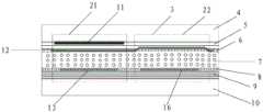
请参考图1,本实施例提供一种透明显示面板,其特征在于,包括阵列分布的像素显示区1,每个所述像素显示区1包括有显示区2和调光区3;Please refer to FIG. 1 , this embodiment provides a transparent display panel, which is characterized in that it includes a
所述透明显示面板包括相对设置的第一基板4和第二基板10,所述第二基板10靠近所述第一基板4的一侧设有像素电极和调光电极16,所述第一基板4靠近所述第二基板10的一侧或者所述第二基板10靠近所述第一基板4的一侧设有遮光层,所述遮光层与所述像素电极相对设置;The transparent display panel includes a first substrate 4 and a
所述透明显示面板设有所述像素电极的区域为所述显示区2,设有所述调光电极16的区域为所述调光区3。The area of the transparent display panel with the pixel electrodes is the display area 2 , and the area with the
本实施例提供的透明显示面板实现透明显示的同时,为显示面板器件增加调光功能,实现了多功能型的透明显示,使得显示面板在具备透明显示功能的同时,还能具有调光功能;具体的通过在进行显示的显示区域旁增加设置调光区,形成如图1所示的结构,其中实现调光功能的调光区在显示面板制备的时候,增加设置调光电极,通过该调光电极实现对液晶层的调节。The transparent display panel provided in this embodiment realizes transparent display, and at the same time adds a dimming function to the display panel device, and realizes a multi-functional transparent display, so that the display panel can also have a dimming function while having a transparent display function; Specifically, by adding a dimming area next to the display area for display, a structure as shown in Figure 1 is formed, wherein the dimming area that realizes the dimming function is added with a dimming electrode when the display panel is prepared, through the dimming The photoelectrode realizes the regulation of the liquid crystal layer.
进一步的,所述显示区2包括第一显示区21和第二显示区22;Further, the display area 2 includes a
所述像素电极包括第一驱动电极13和第二驱动电极14,所述遮光层包括第一遮光层11和第二遮光层15,所述第一基板4靠近所述第二基板10的一侧设有所述第一遮光层11,所述第一遮光层11与所述第一驱动电极13相对设置,所述第二基板10靠近所述第一基板4的一侧设有所述第二遮光层15,所述第二遮光层15与所述第二驱动电极14相对设置;The pixel electrode includes a
设有所述第一驱动电极13的区域为所述第一显示区21,设有所述第二驱动电极14的区域为所述第二显示区22。The area where the
参考图2、图3和图4所示,本实施例提供的透明显示面板具有双面显示的效果,阵列分布的显示区包括有第一显示区和第二显示区,第一显示区用来向第二基板所在的面进行显示,第二显示区用来向第一基板所在的面进行显示,每个第一显示区和第二显示区旁均设有调光区进行调光,实现该透明显示面板的调光功能;本实施例实现双面显示和调光功能,通过聚合物稳定液晶进行控光,当不加电时,器件呈透明态,加电后呈现散射态,实现雾化效果,可以用来进行显示或调光;通过不同功能分区设置,实现双面显示和调光功能。Referring to Fig. 2, Fig. 3 and Fig. 4, the transparent display panel provided by this embodiment has the effect of double-sided display, and the display area distributed in an array includes a first display area and a second display area, and the first display area is used for Display on the surface where the second substrate is located, and the second display area is used to display to the surface where the first substrate is located, and each of the first display area and the second display area is provided with a dimming area for dimming, so as to realize the The dimming function of the transparent display panel; this embodiment realizes the double-sided display and dimming function, and controls the light through the polymer stabilized liquid crystal. When the power is not applied, the device is in a transparent state. Effects can be used for display or dimming; through different functional partition settings, double-sided display and dimming functions can be realized.
如图3所示,不同的显示区通过不同的驱动电极进行驱动,分别设置第一驱动电极和第二驱动电极对第一显示区和第二显示区的液晶层进行驱动;为了实现双面透明显示效果,在该显示面板中分别设置第一遮光层和第二遮光层,靠近第一基板处在第一显示区设置第一遮光层,靠近第二基板处在第二显示区设置第二遮光层,可以实现两个区域分别朝向第一基板的方向和第二基板的方向出光,实现双面显示;As shown in Figure 3, different display areas are driven by different drive electrodes, and the first drive electrodes and the second drive electrodes are respectively set to drive the liquid crystal layers of the first display area and the second display area; in order to realize double-sided transparency Display effect, the first light-shielding layer and the second light-shielding layer are respectively arranged in the display panel, the first light-shielding layer is arranged in the first display area near the first substrate, and the second light-shielding layer is arranged in the second display area near the second substrate layer, which can realize two areas to emit light towards the direction of the first substrate and the direction of the second substrate respectively, and realize double-sided display;
如图4所示,通过增加调光区实现调光效果,该调光区不需要遮光材料的设置,通过聚合物稳定液晶实现调光,只需要在像素电极层同层位置增加设置调光电极,该调光电极与像素电极同层设置,可以同时进行制备,不增加制备步骤。As shown in Figure 4, the dimming effect is achieved by increasing the dimming area. The dimming area does not require the installation of light-shielding materials. The polymer-stabilized liquid crystal is used to achieve dimming. It only needs to add a dimming electrode at the same layer as the pixel electrode layer. , the light-adjusting electrode and the pixel electrode are arranged in the same layer, and can be prepared at the same time without increasing the preparation steps.
进一步的,所述第一基板4靠近所述第二基板10的一侧设有第一平坦层5,所述第一遮光层11设置在所述第一基板5与所述第一平坦层之间5,所述第一平坦层5靠近所述第二基板10的一侧设有公共电极层12,所述公共电极层12靠近所述第二基板10的一侧覆盖有第一取向层6;Further, a first
所述第二基板10靠近所述第一基板4的一侧设有第二平坦层9,所述第二遮光层15设置在所述第二基板10与所述第二平坦层9之间,所述像素电极和所述调光电极16设置在所述第二平坦层8靠近所述第一基板4的一侧,所述像素电极和所述调光电极16靠近所述第一基板4的一侧覆盖有第二取向层8;The side of the
所述第一取向层6和所述第二取向层8之间设有液晶层7。A
如图3和图4所示,本实施例中的双面透明显示面板包括上述层结构,若为单面透明显示面板则只在第一基板或者第二基板处设置遮光层即可,相应的显示区域设置像素电极进行驱动即可。其中,第二基板上的像素电极驱动设计如图6所示,显示区的每个像素可以独立进行控制,为了简化调光区的设计,将调光区的电极进行逐行控制,在显示画面时,只对显示区的像素加电压,调光区不加电压呈透明态;在调光时,可以只对调光区施加电压,或调光区和显示区同时施加电压,从而实现调光功能。As shown in FIG. 3 and FIG. 4, the double-sided transparent display panel in this embodiment includes the above-mentioned layer structure. If it is a single-sided transparent display panel, only a light-shielding layer can be provided on the first substrate or the second substrate. The display area can be driven by setting pixel electrodes. Among them, the driving design of the pixel electrodes on the second substrate is shown in Figure 6. Each pixel in the display area can be independently controlled. In order to simplify the design of the dimming area, the electrodes in the dimming area are controlled row by row. , only apply voltage to the pixels in the display area, and the dimming area is transparent without voltage; when dimming, you can apply voltage only to the dimming area, or apply voltage to both the dimming area and the display area at the same time, so as to realize dimming Function.
进一步的,所述像素电极和所述调光电极16在所述公共电极12上的投影位置处形成镂空结构。Further, the projection position of the pixel electrode and the dimming
如图5所示,本实施例中的公共电极设置在第一基板靠近第一基板的一侧,为了防止上下基板电极交叠处出光,对电极进行镂空处理,将与像素电极和调光电极相对应位置的公共电极进行图案化,相应位置去除,形成图5所示的镂空结构。As shown in Figure 5, the common electrode in this embodiment is arranged on the side of the first substrate close to the first substrate. In order to prevent the light from emerging from the intersection of the electrodes on the upper and lower substrates, the electrode is hollowed out, and it will be connected with the pixel electrode and the dimming electrode. The common electrode at the corresponding position is patterned, and the corresponding position is removed to form the hollow structure shown in FIG. 5 .
进一步的,所述遮光层的范围超出所述像素电极的范围,所述遮光层单侧超出所述像素电极3-15μm。Further, the range of the light-shielding layer is beyond the range of the pixel electrode, and one side of the light-shielding layer is 3-15 μm beyond the pixel electrode.
如图3和图4所示,为了保证该双面透明显示面板双向出光互不干扰,设置的遮光层尺寸需要比相应的像素电极的尺寸大,综合考虑到最后的液晶盒厚,制备工艺中的对位等因素的影响,将遮光层单侧设置的宽于像素电极3μm以上,一般设置为3-15μm。As shown in Figure 3 and Figure 4, in order to ensure that the two-way light output of the double-sided transparent display panel does not interfere with each other, the size of the light-shielding layer needs to be larger than the size of the corresponding pixel electrode. Considering the thickness of the final liquid crystal cell, the preparation process Influenced by factors such as alignment, the one side of the light-shielding layer is set to be wider than the pixel electrode by more than 3 μm, generally set to 3-15 μm.
进一步的,所述第一平坦层6靠近所述第二基板10的一面和/或者所述第二平坦层8靠近所述第一基板4的一面开设凹槽,所述凹槽具体设置在所述调光区22。Further, grooves are provided on the side of the first
如图7和图8所示,为了提高器件的调光效果,提高驱动电压是一种有效的方案,此外,增加液晶盒厚可以提高加电时的雾化效果。因此,通过在第一平坦层和/或者第二平坦层上开槽或图案化的方式来增加调光区的液晶盒厚,可以通过干法刻蚀工艺刻蚀部分或刻透光学平坦层。如图7和图8所示,可以仅对第一基板上的第一平坦层进行处理,也可以对第一平坦层和第二平坦层同时处理,或者对第二平坦层进行处理(图中并未示出),均能实现上述效果。As shown in Figure 7 and Figure 8, in order to improve the dimming effect of the device, increasing the driving voltage is an effective solution. In addition, increasing the thickness of the liquid crystal cell can improve the atomization effect when power is applied. Therefore, the thickness of the liquid crystal cell in the dimming area can be increased by grooves or patterns on the first flat layer and/or the second flat layer, and a part of the optical flat layer can be etched or etched through a dry etching process. As shown in Figures 7 and 8, only the first flat layer on the first substrate can be processed, the first flat layer and the second flat layer can be processed simultaneously, or the second flat layer can be processed (in the figure not shown), all of which can achieve the above effects.
进一步的,所述凹槽的深度为2-3μm。Further, the depth of the groove is 2-3 μm.
同时,为了保证调光效果的同时,工艺难度不过度的增加,将平坦层上的凹槽深度设置为2-3μm。At the same time, in order to ensure the dimming effect and not increase the difficulty of the process excessively, the depth of the groove on the flat layer is set to 2-3 μm.
进一步的,每个所述像素显示区内1的第一驱动电极13和所述第二驱动电极14叉指设置。Further, the
上述实施例中提供了双面透明显示的面板,面板两面均能实现显示效果,为了实现较好的显示效果,可以将第一显示区域和第二显示区域的像素电极进行优化设计,形成叉指设置的形式,形成指状或梳状的面内有周期性图案的电极,可以使得像素电极分布更加均匀,从而减弱显示的颗粒感,提高显示效果;优选的将每个像素出的第一显示区和第二显示区的像素电极设置为交错的结构,如图9、图10和图11所示,给出了几种设置方式,具体的可根据实际情况进行改变。In the above embodiment, a double-sided transparent display panel is provided, and both sides of the panel can achieve a display effect. In order to achieve a better display effect, the pixel electrodes in the first display area and the second display area can be optimally designed to form interdigitated In the form of setting, electrodes with periodic patterns in the finger-like or comb-like surface can be formed, which can make the distribution of pixel electrodes more uniform, thereby reducing the graininess of the display and improving the display effect; preferably, the first display of each pixel The pixel electrodes in the region and the second display region are arranged in a staggered structure, as shown in Fig. 9, Fig. 10 and Fig. 11, several arrangement methods are given, which can be changed according to the actual situation.
进一步的,所述显示区所占面积小于等于所述透明显示面板的50%。Further, the area occupied by the display area is less than or equal to 50% of the transparent display panel.
如图1所示为单侧显示的透明显示面板,如图2所示的为双面显示的透明显示面板,其中包括至少一个显示区域和一个调光区域,显示区域和调光区域之间的均为透明非显示区域,实现显示面板透明的效果;其中,通过调节显示区域和调光区域的面积比例来调节透过率和显示效果,一般情况下,为了保证有较高的透过率,一个显示区域或者两个显示区域所占面积设置在显示面板的50%之内。As shown in Figure 1, it is a transparent display panel with one-sided display, and as shown in Figure 2, it is a transparent display panel with double-sided display, which includes at least one display area and one dimming area, and the distance between the display area and the dimming area Both are transparent non-display areas to achieve the transparent effect of the display panel; among them, the transmittance and display effect are adjusted by adjusting the area ratio of the display area and the dimming area. Generally, in order to ensure a high transmittance, The area occupied by one display area or two display areas is set within 50% of the display panel.
本实施例还提供一种显示装置,包括上述透明显示面板。This embodiment also provides a display device, including the above-mentioned transparent display panel.
本实施例还提供上述双面透明显示面板的制备方法,首先提供第二基板,该第二基板指的就是图中的下基板,首先在第二基板上进行对位标记和金属导线的设置,该金属导线可以采用常规的金属,例如钼、铝、铜、银等等,可以采用其他透明导电材料制备;This embodiment also provides a method for preparing the above-mentioned double-sided transparent display panel. Firstly, a second substrate is provided. The second substrate refers to the lower substrate in the figure. Firstly, alignment marks and metal wires are arranged on the second substrate. The metal wire can be made of conventional metals, such as molybdenum, aluminum, copper, silver, etc., and can be made of other transparent conductive materials;
随后在第二基板上进行第二遮光层的制备,在第二基板上涂覆黑矩阵光学胶,对该光学胶进行图案化形成第二遮光层,该第二遮光层的厚度一般为1-2μm;Carry out the preparation of the second light-shielding layer on the second substrate subsequently, coat black matrix optical glue on the second substrate, carry out patterning to this optical glue and form the second light-shielding layer, the thickness of this second light-shielding layer is generally 1- 2μm;
随后在第二遮光层上形成第二平坦层,通过在第二基板上涂覆光学透明胶,该光学透明胶厚度大于第二遮光层的厚度,覆盖该第二遮光层设置,该第二平坦层厚度一般为2-5μm,优选的设置为2-3μm,并且第二平坦层上对应设置金属导线的区域进行刻蚀形成过孔,以便于后续像素电极与金属导线之间的电连接,并且刻蚀形成的过孔不能暴露第二遮光层的表面;Then a second flat layer is formed on the second light-shielding layer, by coating an optically transparent glue on the second substrate, the thickness of the optically transparent glue is greater than the thickness of the second light-shielding layer, covering the second light-shielding layer, the second flat The layer thickness is generally 2-5 μm, preferably set to 2-3 μm, and the area corresponding to the metal wire is etched on the second flat layer to form a via hole, so as to facilitate the electrical connection between the subsequent pixel electrode and the metal wire, and The via holes formed by etching cannot expose the surface of the second light-shielding layer;
随后在第二平坦层上形成像素电极和调光电极,该像素电极和调光电极均为透明电极层,通过上步骤形成的过孔与金属导线相连,该步骤中先在第二平坦层上形成透明电极层,根据需求进行图案化,形成相应的像素电极区域和调光电极区域,该透明电极层的厚度一般设置为400-1500埃,优选的厚度为700-800埃,形成的像素电极范围需要小于之前形成的第二遮光层的范围,通常第二遮光层和像素电极均为阵列分布的矩形结构,该第二遮光层单边宽度超过该像素电极3μm以上,考虑到液晶盒厚、制备工艺对位等因素的影响;Subsequently, a pixel electrode and a dimming electrode are formed on the second flat layer, and the pixel electrode and the dimming electrode are both transparent electrode layers, and are connected to metal wires through the via holes formed in the previous step. Form a transparent electrode layer, pattern it according to requirements, and form the corresponding pixel electrode area and dimming electrode area. The thickness of the transparent electrode layer is generally set to 400-1500 angstroms, and the preferred thickness is 700-800 angstroms. The formed pixel electrode The range needs to be smaller than the range of the previously formed second light-shielding layer. Usually, the second light-shielding layer and the pixel electrodes are rectangular structures distributed in an array. The width of one side of the second light-shielding layer exceeds the pixel electrode by more than 3 μm. The influence of the preparation process on the position and other factors;
随后在透明电极层上形成第二取向层,通过涂覆液晶配向材料,并通过摩擦或者光配向技术完成取向。Subsequently, a second alignment layer is formed on the transparent electrode layer, by coating a liquid crystal alignment material, and the alignment is completed by rubbing or photo-alignment technology.
然后提供第一基板,该第一基板为图中的上基板,在第一基板上进行对位标记的设置,随后在第一基板上进行第一遮光层的制备,在第一基板上涂覆黑矩阵光学胶,对该光学胶进行图案化形成第一遮光层,该第一遮光层的厚度一般为1-2μm;Then provide the first substrate, the first substrate is the upper substrate in the figure, set the alignment mark on the first substrate, then prepare the first light-shielding layer on the first substrate, and coat the first light-shielding layer on the first substrate. Black matrix optical glue, patterning the optical glue to form a first light-shielding layer, the thickness of the first light-shielding layer is generally 1-2 μm;
随后在第一遮光层上形成第一平坦层,通过在第一基板上涂覆光学透明胶,该光学透明胶厚度大于第一遮光层的厚度,覆盖该第一遮光层设置,该第一平坦层厚度一般为2-5μm,优选的设置为2-3μm;Then a first flat layer is formed on the first light-shielding layer, by coating an optically transparent glue on the first substrate, the thickness of the optically transparent glue is greater than the thickness of the first light-shielding layer, covering the first light-shielding layer, the first flat The layer thickness is generally 2-5μm, and the preferred setting is 2-3μm;
随后在第一平坦层上形成公共电极层,该公共电极层采用透明电极材料进行制备,随后制作光敏间隙控制柱,一般高度为2-5μm,优选的设置为2.5-3.5μm,随后制备第一取向层;Then a common electrode layer is formed on the first flat layer, the common electrode layer is prepared by using a transparent electrode material, and then a photosensitive gap control column is made, generally with a height of 2-5 μm, preferably 2.5-3.5 μm, and then the first orientation layer;
随后进行对盒和灌晶,从而完成液晶盒制作,液晶层由至少三组分构成,一种或多种液晶分子,一种或多种可光聚合的单体分子,如含有乙烯基的单体,以及光引发剂。可聚合单体和液晶分子之间的相容性要比较好。液晶混合物中,可聚合单体的比例一般在10%以下,优选在的3%~9%,液晶分子的介电常数差较大的材料为佳。入光的方向与液晶层配向的方向垂直。灌晶完成后,进行紫外(UV)光照射,使其中的光敏液晶分子聚合形成聚合物网络,最终形成聚合物稳定的液晶(PSLC);也可通过热聚合或红外聚合等方式形成高分子,如此,完成器件的制作。Subsequent cell alignment and filling are carried out to complete the production of liquid crystal cells. The liquid crystal layer is composed of at least three components, one or more liquid crystal molecules, and one or more photopolymerizable monomer molecules, such as monomers containing vinyl groups. bodies, and photoinitiators. The compatibility between the polymerizable monomer and the liquid crystal molecules is better. In the liquid crystal mixture, the proportion of the polymerizable monomer is generally below 10%, preferably 3% to 9%, and the material with a large difference in the dielectric constant of the liquid crystal molecules is preferred. The direction of incident light is perpendicular to the alignment direction of the liquid crystal layer. After the filling is completed, ultraviolet (UV) light is irradiated to polymerize the photosensitive liquid crystal molecules to form a polymer network, and finally form a polymer-stabilized liquid crystal (PSLC); polymers can also be formed by thermal polymerization or infrared polymerization. In this way, the fabrication of the device is completed.
上述实施例中的透明单面显示面板的制备方法与上述双面透明显示面板的制备方法类似,其中只设置第一遮光层或者只设置第二遮光层即可。The preparation method of the transparent single-sided display panel in the above embodiment is similar to the preparation method of the above-mentioned double-sided transparent display panel, wherein only the first light-shielding layer or only the second light-shielding layer is provided.
其中,为了提高器件的调光效果,可以采用提高驱动电压的方式,或者采用增加液晶盒盒厚方式提高加电时的雾化效果,因此,可以在上述第一平坦层或者第二平坦层制备的过程中,在第一平坦层和/或者第二平坦层上开设凹槽,具体设置在调光区所在的位置,可以通过干法刻蚀工艺刻蚀部分平坦层,形成如图7或者图8所示的结构,实现提高器件的调光效果的目的。Among them, in order to improve the dimming effect of the device, the method of increasing the driving voltage can be used, or the method of increasing the thickness of the liquid crystal cell can be used to improve the atomization effect when power is applied. Therefore, it can be prepared on the first flat layer or the second flat layer. In the process, a groove is opened on the first flat layer and/or the second flat layer, specifically at the position where the dimming area is located, and a part of the flat layer can be etched by a dry etching process to form a flat layer as shown in Figure 7 or The structure shown in 8 achieves the purpose of improving the dimming effect of the device.
以上描述仅为本申请的较佳实施例以及对所运用技术原理的说明。本领域技术人员应当理解,本申请中所涉及的发明范围,并不限于上述技术特征的特定组合而成的技术方案,同时也应涵盖在不脱离所述发明构思的情况下,由上述技术特征或其等同特征进行任意组合而形成的其它技术方案。例如上述特征与本申请中公开的(但不限于)具有类似功能的技术特征进行互相替换而形成的技术方案。The above description is only a preferred embodiment of the present application and an illustration of the applied technical principle. Those skilled in the art should understand that the scope of the invention involved in this application is not limited to the technical solution formed by the specific combination of the above-mentioned technical features, but should also cover the technical solution formed by the above-mentioned technical features without departing from the inventive concept. Other technical solutions formed by any combination of or equivalent features thereof. For example, a technical solution formed by replacing the above-mentioned features with technical features with similar functions disclosed in (but not limited to) this application.
Claims (7)
Translated fromChinesePriority Applications (1)
| Application Number | Priority Date | Filing Date | Title |
|---|---|---|---|
| CN202110524148.5ACN113238415B (en) | 2021-05-13 | 2021-05-13 | Transparent display panel and display device |
Applications Claiming Priority (1)
| Application Number | Priority Date | Filing Date | Title |
|---|---|---|---|
| CN202110524148.5ACN113238415B (en) | 2021-05-13 | 2021-05-13 | Transparent display panel and display device |
Publications (2)
| Publication Number | Publication Date |
|---|---|
| CN113238415A CN113238415A (en) | 2021-08-10 |
| CN113238415Btrue CN113238415B (en) | 2023-05-23 |
Family
ID=77134191
Family Applications (1)
| Application Number | Title | Priority Date | Filing Date |
|---|---|---|---|
| CN202110524148.5AActiveCN113238415B (en) | 2021-05-13 | 2021-05-13 | Transparent display panel and display device |
Country Status (1)
| Country | Link |
|---|---|
| CN (1) | CN113238415B (en) |
Families Citing this family (1)
| Publication number | Priority date | Publication date | Assignee | Title |
|---|---|---|---|---|
| WO2024020873A1 (en)* | 2022-07-27 | 2024-02-01 | 京东方科技集团股份有限公司 | Display panel and preparing method therefor, and display device |
Citations (2)
| Publication number | Priority date | Publication date | Assignee | Title |
|---|---|---|---|---|
| CN104020604A (en)* | 2014-06-18 | 2014-09-03 | 南京中电熊猫液晶显示科技有限公司 | Two-sided transparent display device |
| CN110824771A (en)* | 2019-11-12 | 2020-02-21 | 昆山龙腾光电股份有限公司 | Display device and driving method thereof |
Family Cites Families (17)
| Publication number | Priority date | Publication date | Assignee | Title |
|---|---|---|---|---|
| KR100692688B1 (en)* | 2004-04-08 | 2007-03-14 | 비오이 하이디스 테크놀로지 주식회사 | Liquid crystal display with double side display |
| CN103293793B (en)* | 2013-05-31 | 2016-06-01 | 京东方科技集团股份有限公司 | A kind of double face display panel and manufacture method thereof |
| CN103345884B (en)* | 2013-06-26 | 2016-03-09 | 京东方科技集团股份有限公司 | double-side display device and preparation method thereof |
| CN104155791B (en)* | 2014-07-11 | 2017-01-18 | 京东方科技集团股份有限公司 | Double-sided display panel and double-sided display device |
| CN104298031A (en)* | 2014-11-05 | 2015-01-21 | 京东方科技集团股份有限公司 | Liquid crystal display panel and display device |
| CN105445999A (en)* | 2016-01-11 | 2016-03-30 | 京东方科技集团股份有限公司 | Dual-face display |
| CN105789256A (en)* | 2016-03-18 | 2016-07-20 | 京东方科技集团股份有限公司 | OLED (organic light-emitting diode) two-sided display substrate, manufacturing method, and display |
| CN105954937B (en)* | 2016-07-13 | 2019-02-12 | 京东方科技集团股份有限公司 | Display panel, method for making the same, and display device |
| CN105954933B (en)* | 2016-07-21 | 2019-01-18 | 京东方科技集团股份有限公司 | Display device and preparation method thereof |
| CN206710760U (en)* | 2017-05-12 | 2017-12-05 | 北京京东方光电科技有限公司 | A kind of shooting part, display device |
| CN109765717B (en)* | 2019-03-20 | 2021-01-22 | 京东方科技集团股份有限公司 | Pixel structure and driving method thereof, array substrate and display device |
| CN110018596A (en)* | 2019-04-08 | 2019-07-16 | 成都中电熊猫显示科技有限公司 | A kind of array substrate, display panel and electronic device |
| CN111983864A (en)* | 2019-05-24 | 2020-11-24 | 京东方科技集团股份有限公司 | Light-adjusting glass |
| CN110632802B (en)* | 2019-09-25 | 2021-02-23 | 武汉华星光电技术有限公司 | Array substrate, display panel and manufacturing method of array substrate |
| CN211454169U (en)* | 2019-12-12 | 2020-09-08 | 京东方科技集团股份有限公司 | Light-adjusting glass and glass module |
| CN111025788A (en)* | 2019-12-17 | 2020-04-17 | 深圳市华星光电半导体显示技术有限公司 | Display device |
| CN111766733A (en)* | 2020-07-31 | 2020-10-13 | 京东方科技集团股份有限公司 | Transparent display panel, preparation method thereof, and display device |
- 2021
- 2021-05-13CNCN202110524148.5Apatent/CN113238415B/enactiveActive
Patent Citations (2)
| Publication number | Priority date | Publication date | Assignee | Title |
|---|---|---|---|---|
| CN104020604A (en)* | 2014-06-18 | 2014-09-03 | 南京中电熊猫液晶显示科技有限公司 | Two-sided transparent display device |
| CN110824771A (en)* | 2019-11-12 | 2020-02-21 | 昆山龙腾光电股份有限公司 | Display device and driving method thereof |
Also Published As
| Publication number | Publication date |
|---|---|
| CN113238415A (en) | 2021-08-10 |
Similar Documents
| Publication | Publication Date | Title |
|---|---|---|
| US6104460A (en) | Reflective LCD with cylindrical pattern formed in reflecting electrode region | |
| US10048505B2 (en) | Grating, display device, and manufacturing method of grating | |
| KR20000029250A (en) | A reflective color liquid crystal display apparatus | |
| GB2296809A (en) | Liquid crystal display | |
| WO2019223203A1 (en) | Method for building polarizer in liquid crystal panel, and liquid crystal display device and manufacturing method therefor | |
| JP2000047200A (en) | Diffuse reflector, liquid crystal display device using the same and method of manufacturing the same | |
| TW200422725A (en) | Substrate for electro-optical device, method of manufacturing substrate for electro-optical device, electro-optical device and electronic apparatus | |
| CN107957638A (en) | A kind of preparation method of flexibility LCD | |
| JP3490375B2 (en) | Manufacturing method of liquid crystal display device | |
| CN113238415B (en) | Transparent display panel and display device | |
| CN110262115A (en) | Display panel and its manufacturing method, display device | |
| WO2001061403A1 (en) | Formed body, reflecting plate, reflection display device, and method for fabricating reflecting plate | |
| JPH05181117A (en) | Dispersed liquid crystal electro-optical device | |
| CN111073664A (en) | Liquid crystal material, preparation method of liquid crystal display panel and display panel | |
| CN212460254U (en) | Color electronic paper with reticular filter film | |
| JP2001242452A (en) | Liquid crystal display | |
| US6445438B1 (en) | Liquid crystal display device and method for fabricating the same | |
| JPH10301129A (en) | Liquid crystal display device and its production | |
| CN100351677C (en) | Liquid crystal display device containing nano polymer network and its manufacturing method | |
| CN1306287C (en) | Colour filter, display and mfg. method thereof | |
| JP2004279765A (en) | Color filter for liquid crystal display device and liquid crystal display device | |
| JP2000321568A (en) | Reflective liquid crystal display | |
| WO2023097789A1 (en) | Display panel and method for preparing same, display apparatus | |
| CN111562697A (en) | A color electronic paper with a mesh filter | |
| KR100506072B1 (en) | Fabrication method of Liquid Crystal Display |
Legal Events
| Date | Code | Title | Description |
|---|---|---|---|
| PB01 | Publication | ||
| PB01 | Publication | ||
| SE01 | Entry into force of request for substantive examination | ||
| SE01 | Entry into force of request for substantive examination | ||
| GR01 | Patent grant | ||
| GR01 | Patent grant |