CN113230095B - Foot mechanism of lower limb exoskeleton and lower limb exoskeleton - Google Patents
Foot mechanism of lower limb exoskeleton and lower limb exoskeletonDownload PDFInfo
- Publication number
- CN113230095B CN113230095BCN202110507665.1ACN202110507665ACN113230095BCN 113230095 BCN113230095 BCN 113230095BCN 202110507665 ACN202110507665 ACN 202110507665ACN 113230095 BCN113230095 BCN 113230095B
- Authority
- CN
- China
- Prior art keywords
- instep strap
- slider
- foot
- instep
- installation cavity
- Prior art date
- Legal status (The legal status is an assumption and is not a legal conclusion. Google has not performed a legal analysis and makes no representation as to the accuracy of the status listed.)
- Active
Links
- 210000003141lower extremityAnatomy0.000titleclaimsabstractdescription20
- 238000009434installationMethods0.000claimsabstractdescription36
- 238000005452bendingMethods0.000claimsdescription12
- 238000010586diagramMethods0.000description4
- 208000035657AbasiaDiseases0.000description1
- 206010033799ParalysisDiseases0.000description1
- 230000032683agingEffects0.000description1
- 230000009286beneficial effectEffects0.000description1
- 238000000034methodMethods0.000description1
- 230000009466transformationEffects0.000description1
Images


Classifications
- A—HUMAN NECESSITIES
- A61—MEDICAL OR VETERINARY SCIENCE; HYGIENE
- A61H—PHYSICAL THERAPY APPARATUS, e.g. DEVICES FOR LOCATING OR STIMULATING REFLEX POINTS IN THE BODY; ARTIFICIAL RESPIRATION; MASSAGE; BATHING DEVICES FOR SPECIAL THERAPEUTIC OR HYGIENIC PURPOSES OR SPECIFIC PARTS OF THE BODY
- A61H3/00—Appliances for aiding patients or disabled persons to walk about
- A61H2003/005—Appliances for aiding patients or disabled persons to walk about with knee, leg or stump rests
- A—HUMAN NECESSITIES
- A61—MEDICAL OR VETERINARY SCIENCE; HYGIENE
- A61H—PHYSICAL THERAPY APPARATUS, e.g. DEVICES FOR LOCATING OR STIMULATING REFLEX POINTS IN THE BODY; ARTIFICIAL RESPIRATION; MASSAGE; BATHING DEVICES FOR SPECIAL THERAPEUTIC OR HYGIENIC PURPOSES OR SPECIFIC PARTS OF THE BODY
- A61H2201/00—Characteristics of apparatus not provided for in the preceding codes
- A61H2201/12—Driving means
- A61H2201/1207—Driving means with electric or magnetic drive
- A—HUMAN NECESSITIES
- A61—MEDICAL OR VETERINARY SCIENCE; HYGIENE
- A61H—PHYSICAL THERAPY APPARATUS, e.g. DEVICES FOR LOCATING OR STIMULATING REFLEX POINTS IN THE BODY; ARTIFICIAL RESPIRATION; MASSAGE; BATHING DEVICES FOR SPECIAL THERAPEUTIC OR HYGIENIC PURPOSES OR SPECIFIC PARTS OF THE BODY
- A61H2201/00—Characteristics of apparatus not provided for in the preceding codes
- A61H2201/16—Physical interface with patient
- A61H2201/1602—Physical interface with patient kind of interface, e.g. head rest, knee support or lumbar support
- A61H2201/164—Feet or leg, e.g. pedal
- A61H2201/1642—Holding means therefor
- Y—GENERAL TAGGING OF NEW TECHNOLOGICAL DEVELOPMENTS; GENERAL TAGGING OF CROSS-SECTIONAL TECHNOLOGIES SPANNING OVER SEVERAL SECTIONS OF THE IPC; TECHNICAL SUBJECTS COVERED BY FORMER USPC CROSS-REFERENCE ART COLLECTIONS [XRACs] AND DIGESTS
- Y02—TECHNOLOGIES OR APPLICATIONS FOR MITIGATION OR ADAPTATION AGAINST CLIMATE CHANGE
- Y02A—TECHNOLOGIES FOR ADAPTATION TO CLIMATE CHANGE
- Y02A50/00—TECHNOLOGIES FOR ADAPTATION TO CLIMATE CHANGE in human health protection, e.g. against extreme weather
- Y02A50/30—Against vector-borne diseases, e.g. mosquito-borne, fly-borne, tick-borne or waterborne diseases whose impact is exacerbated by climate change
Landscapes
- Health & Medical Sciences (AREA)
- Epidemiology (AREA)
- Pain & Pain Management (AREA)
- Physical Education & Sports Medicine (AREA)
- Rehabilitation Therapy (AREA)
- Life Sciences & Earth Sciences (AREA)
- Animal Behavior & Ethology (AREA)
- General Health & Medical Sciences (AREA)
- Public Health (AREA)
- Veterinary Medicine (AREA)
- Orthopedics, Nursing, And Contraception (AREA)
Abstract
Translated fromChinese
Description
Translated fromChinese技术领域technical field
本发明涉及外骨骼领域,具体涉及下肢外骨骼的脚部机构以及下肢外骨骼。The invention relates to the field of exoskeleton, in particular to a foot mechanism of the exoskeleton for lower limbs and the exoskeleton for lower limbs.
背景技术Background technique
在日常生活中,常有人因为各种原因无法行走。如由于中风导致腿部麻痹,或者由于年龄增长导致腿部力量不足,无法长时间行走。多个现有技术表明,下肢外骨骼在辅助下肢行走和医学康复领域得到了越来越广泛的应用。In daily life, people are often unable to walk due to various reasons. Such as paralysis of the legs due to a stroke, or lack of strength in the legs due to aging and cannot walk for a long time. A number of prior art shows that the lower extremity exoskeleton has been more and more widely used in the field of assisted lower limb walking and medical rehabilitation.
现有外骨骼的脚部机构通过人工穿戴,且不能调节固定点的前后位置,使用舒适性较差。The foot mechanism of the existing exoskeleton is manually worn, and the front and rear positions of the fixed points cannot be adjusted, so the use comfort is poor.
发明内容Contents of the invention
本发明针对上述问题,提出了下肢外骨骼的脚部机构以及下肢外骨骼。Aiming at the above problems, the present invention proposes a foot mechanism of a lower limb exoskeleton and a lower limb exoskeleton.
本发明采取的技术方案如下:The technical scheme that the present invention takes is as follows:
一种下肢外骨骼的脚部机构,包括:A foot mechanism of a lower extremity exoskeleton, comprising:
脚底座,内部具有安装腔,脚底座的两侧均设置有滑轨,脚底座的两侧还具有与滑轨平行的第一条形孔,所述条形孔与安装腔连通,脚底座其中一侧还具有与安装腔连通的第二条形孔,所述第二条形孔与第一条形孔平行;The foot base has an installation cavity inside, and both sides of the foot base are provided with slide rails, and both sides of the foot base also have a first strip-shaped hole parallel to the slide rails, and the strip-shaped holes communicate with the installation cavity. One side also has a second strip-shaped hole communicating with the installation cavity, and the second strip-shaped hole is parallel to the first strip-shaped hole;
脚跟挡板,固定在脚底座上端面的后端;The heel baffle is fixed on the rear end of the upper end surface of the foot base;
第一滑块,滑动设置在脚底座一侧的滑轨上;The first slider is slidably arranged on the slide rail on one side of the foot base;
第二滑块,滑动设置在脚底座另一侧的滑轨上,第二滑块上具有通过口,所述第二滑块和第二条形孔位于脚底座的同一侧;The second slider is slidably arranged on the slide rail on the other side of the foot base, the second slider has a passage opening, and the second slider and the second bar-shaped hole are located on the same side of the foot base;
连接杆,设置在安装腔内,且两端穿过对应的第一条形孔后与对应的滑块固定;The connecting rod is arranged in the installation cavity, and the two ends pass through the corresponding first strip hole and are fixed to the corresponding slider;
驱动齿轮,位于安装腔内,转动安装在连接杆上;The driving gear is located in the installation cavity and is rotatably installed on the connecting rod;
驱动电机,与连接杆固定,用于驱动所述驱动齿轮转动;A drive motor, fixed to the connecting rod, is used to drive the drive gear to rotate;
脚背绑带,脚背绑带的第一端与所述第一滑块固定,脚背绑带的第二端依次穿过所述通过口和所述第二条形孔后伸入所述安装腔,脚背绑带的第二端间隔设置有多个凹槽,所述驱动齿轮与凹槽啮合,通过驱动齿轮的转动能够调节脚背绑带的松紧。The instep strap, the first end of the instep strap is fixed to the first slider, and the second end of the instep strap passes through the passage port and the second strip hole in turn and then extends into the installation cavity, The second end of the instep strap is provided with a plurality of grooves at intervals, and the driving gear is engaged with the groove, and the tightness of the instep strap can be adjusted through the rotation of the driving gear.
本申请的脚步机构,通过连接杆连接第一滑块和第二滑块,使得两个滑块能够同步的在滑轨上移动,即可以根据需要调节脚背绑带的位置,从而更好的适配不同长度的脚;通过驱动齿轮与脚背绑带凹槽的啮合配合,能够通过驱动电机自动调节脚背绑带的松紧,无需手动调节,穿戴更方便。The foot mechanism of the present application connects the first slider and the second slider through the connecting rod, so that the two sliders can move synchronously on the slide rail, that is, the position of the instep strap can be adjusted according to needs, so as to better adapt to the situation. It is equipped with feet of different lengths; through the engagement of the drive gear and the groove of the instep strap, the tightness of the instep strap can be automatically adjusted by the drive motor, without manual adjustment, and it is more convenient to wear.
于本发明其中一实施例中,还包括驱动组件,所述驱动组件用于驱动两个滑块同步移动。In one embodiment of the present invention, a driving assembly is further included, and the driving assembly is used to drive the two sliders to move synchronously.
于本发明其中一实施例中,所述连接杆上具有螺纹孔,所述驱动组件包括:In one embodiment of the present invention, the connecting rod has a threaded hole, and the driving assembly includes:
丝杆,转动安装在安装腔内,丝杆穿过所述螺纹孔且与螺纹孔啮合;The screw rod is rotatably installed in the installation cavity, and the screw rod passes through the threaded hole and engages with the threaded hole;
调节电机,安装在安装腔内,用于驱动所述丝杆转动。The adjusting motor is installed in the installation cavity and is used to drive the screw to rotate.
通过调节电机的转动能够带动连接杆移动,即带动两个滑块和脚背绑带移动。By adjusting the rotation of the motor, the connecting rod can be driven to move, that is, the two sliders and the instep straps can be driven to move.
于本发明其中一实施例中,所述滑轨包括梯形防脱槽,脚底座两侧均设置两个平行设置的滑轨,所述滑块具有嵌入对应梯形防脱槽的梯形部。In one embodiment of the present invention, the slide rail includes a trapezoidal anti-falling groove, two parallel sliding rails are arranged on both sides of the foot base, and the slider has a trapezoidal portion embedded in the corresponding trapezoidal anti-falling groove.
于本发明其中一实施例中,所述第二滑块具有与通过口连通的安装槽,所述安装槽内安装有防脱件、扭簧以及解锁元件;In one embodiment of the present invention, the second slider has a mounting groove communicating with the passage opening, and the mounting groove is equipped with a detachment preventing member, a torsion spring and an unlocking element;
所述防脱件转动安装在所述安装槽内,防脱件具有用于伸入凹槽的弯折部,所述扭簧外套在防脱件上,用于使所述弯折部具有向脚背绑带一侧转动的转动趋势;脚背绑带位于通过口的部分受到向下的力时,能够带动弯折部克服扭簧的弹性力转动,脚背绑带能够相对第二滑块相下移动;脚背绑带位于通过口的部分受到向上的力时,通过弯折部与凹槽的配合,能够阻止脚背绑带相对第二滑块上移;The anti-off piece is rotatably installed in the installation groove, and the anti-off piece has a bent part for extending into the groove, and the torsion spring is covered on the anti-off part, so that the bent part has a direction The rotation trend of one side of the instep strap turning; when the part of the instep strap located at the passage port receives a downward force, it can drive the bending part to overcome the elastic force of the torsion spring to rotate, and the instep strap can move downward relative to the second slider ; When the part of the instep strap located at the passage port is subjected to an upward force, the instep strap can be prevented from moving up relative to the second slider through the cooperation of the bending part and the groove;
所述解锁元件通过连接件与防脱件配合,用于使弯折部脱离脚背绑带的凹槽。The unlocking element cooperates with the anti-off piece through the connecting piece, and is used to make the bending part break away from the groove of the instep strap.
实际运用时,所述解锁元件为电磁铁或舵机等结构,连接件可以为细绳等结构。In practice, the unlocking element is a structure such as an electromagnet or a steering gear, and the connecting piece may be a structure such as a string.
于本发明其中一实施例中,所述脚背绑带面向脚底板的侧壁上安装有第一压力传感器,所述第一压力传感器用于探测脚背绑带与脚背之间的压力。In one embodiment of the present invention, a first pressure sensor is installed on the side wall of the instep strap facing the sole, and the first pressure sensor is used to detect the pressure between the instep strap and the instep.
实际运用时,可以设定多档松紧程度,比如紧、较紧以及松三个档位,每个档位的压力范围不同,紧档位的最小压力大于较紧档位的最大压力,较紧档位的最小压力大于松档位的最大压力,用户可以根据需要选定档位,通过驱动电机配合第一压力传感器能够自动调节至设定档位。In actual use, you can set multiple levels of tightness, such as three levels of tight, tight and loose. The pressure range of each level is different. The minimum pressure of the tight level is greater than the maximum pressure of the tighter level. The minimum pressure of the gear position is greater than the maximum pressure of the loose gear position. The user can select the gear position according to the needs, and the gear can be automatically adjusted to the set gear position through the driving motor and the first pressure sensor.
于本发明其中一实施例中,所述脚底座的上表面安装或嵌装有多组第二压力传感器,各组第二压力传感器沿脚底座的长度方向间隔设置。In one embodiment of the present invention, multiple sets of second pressure sensors are installed or embedded on the upper surface of the foot base, and each set of second pressure sensors is arranged at intervals along the length direction of the foot base.
设置多组第二压力传感器能够大致判断出较长,即脚长可以简单等价于:测得压力信号的最远离脚跟挡板的一组第二压力传感器距脚跟挡板的距离。Setting multiple sets of second pressure sensors can roughly determine the longer length, that is, the length of the foot can be simply equivalent to: the distance between the group of second pressure sensors that is farthest from the heel guard and the measured pressure signal from the heel guard.
每组第二压力传感器包括多个间隔设置的第二压力传感器,实际运用时,通过第二压力传感器的测得的压力分布可以判断脚底位置是否准确,脚部受力是否正常。Each group of second pressure sensors includes a plurality of second pressure sensors arranged at intervals. In actual use, the pressure distribution measured by the second pressure sensors can determine whether the position of the sole of the foot is accurate and whether the force on the foot is normal.
于本发明其中一实施例中,脚部机构进行自动调节和绑紧的步骤为:In one embodiment of the present invention, the steps of automatic adjustment and tightening of the foot mechanism are as follows:
脚伸入脚背绑带内,且使脚后跟与脚跟挡板相抵;Put your foot into the instep strap and bring your heel against the heel guard;
多个第二压力传感器测得压力信号,确定测得压力信号的最远离脚跟挡板的一组第二压力传感器,该组第二压力传感器距脚跟挡板的距离为X;A plurality of second pressure sensors measure pressure signals, and determine a group of second pressure sensors that are farthest from the heel baffle for the measured pressure signals, and the distance between the group of second pressure sensors and the heel baffle is X;
驱动组件工作,带动第一滑块和第二滑块滑动,使脚背绑带距脚跟挡板的距离为0.5X~0.7X;The driving component works to drive the first slider and the second slider to slide, so that the distance between the instep strap and the heel baffle is 0.5X to 0.7X;
驱动电机工作,使脚背绑带收紧,直至第一压力传感器测得的压力在设定范围内。The driving motor works to tighten the instep strap until the pressure measured by the first pressure sensor is within the set range.
于本发明其中一实施例中,所述脚底座内固定有限位板,所述限位板与驱动齿轮位于第二条形孔的上下两侧,脚背绑带伸入安装腔的部分与所述限位板滑动配合。In one embodiment of the present invention, the limiting plate is fixed inside the base of the foot, the limiting plate and the driving gear are located on the upper and lower sides of the second bar-shaped hole, and the part of the instep strap extending into the installation cavity is connected to the The limit plate is a slip fit.
通过限位板能够配合驱动齿轮可靠的驱动脚背绑带向安装腔内移动或向安装腔外移动。Through the limiting plate, the instep strap can be reliably driven to move into the installation cavity or to move outside the installation cavity in cooperation with the drive gear.
于本发明其中一实施例中,所述脚跟挡板为弧形,脚部机构还包括可拆卸安装在脚跟挡板上的弧形套,所述弧形套有多个,不同弧形套的弧度不同。In one embodiment of the present invention, the heel baffle is arc-shaped, and the foot mechanism further includes an arc-shaped sleeve detachably mounted on the heel baffle. There are multiple arc-shaped sleeves, and different arc-shaped sleeves The arc is different.
本申请还公开了一种下肢外骨骼,包括上文所述的脚部机构。The application also discloses a lower extremity exoskeleton, including the above-mentioned foot mechanism.
本发明的有益效果是:本申请的脚步机构,通过连接杆连接第一滑块和第二滑块,使得两个滑块能够同步的在滑轨上移动,即可以根据需要调节脚背绑带的位置,从而更好的适配不同长度的脚;通过驱动齿轮与脚背绑带凹槽的啮合配合,能够通过驱动电机自动调节脚背绑带的松紧,无需手动调节,穿戴更方便。The beneficial effects of the present invention are: the foot mechanism of the present application connects the first slider and the second slider through the connecting rod, so that the two sliders can move synchronously on the slide rail, that is, the instep strap can be adjusted as required. Position, so as to better adapt to feet of different lengths; through the engagement of the drive gear and the groove of the instep strap, the tightness of the instep strap can be automatically adjusted by the drive motor, without manual adjustment, and it is more convenient to wear.
附图说明:Description of drawings:
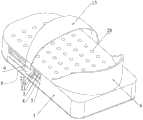
图1是本申请下肢外骨骼的脚部机构的结构示意图;Fig. 1 is the schematic structural diagram of the foot mechanism of the lower extremity exoskeleton of the present application;
图2是本申请下肢外骨骼的脚部机构另一角度的结构示意图;Fig. 2 is a structural schematic diagram of another angle of the foot mechanism of the lower extremity exoskeleton of the present application;
图3是本申请下肢外骨骼的脚部机构的俯视图;Fig. 3 is the top view of the foot mechanism of the lower extremity exoskeleton of the present application;
图4是图3的A-A剖视图;Fig. 4 is A-A sectional view of Fig. 3;
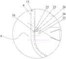
图5是图4中B处的放大图;Fig. 5 is the enlarged view of place B in Fig. 4;
图6是滑块、连接杆、脚背绑带、驱动齿轮、驱动电机以及驱动组件的示意图;Fig. 6 is a schematic diagram of a slider, a connecting rod, an instep strap, a driving gear, a driving motor and a driving assembly;
图7是脚底座的局部示意图;Fig. 7 is a partial schematic view of the foot base;
图8是图7省略限位板后的示意图。FIG. 8 is a schematic diagram of FIG. 7 omitting the limiting plate.
图中各附图标记为:Each reference mark in the figure is:
1、脚底座;2、安装腔;3、滑轨;4、第一条形孔;5、第二条形孔;6、脚跟挡板;7、第一滑块;8、第二滑块;9、通过口;10、连接杆;11、驱动齿轮;12、驱动电机;13、脚背绑带;14、第一端;15、第二端;16、凹槽;17、驱动组件;18、螺纹孔;19、丝杆;20、调节电机;21、梯形部;22、安装槽;23、防脱件;24、解锁元件;25、弯折部;26、连接件;27、第一压力传感器;28、第二压力传感器;29、限位板。1. Foot base; 2. Installation cavity; 3. Slide rail; 4. The first strip hole; 5. The second strip hole; 6. Heel baffle; 7. The first slider; 8. The second slider ;9, passage port; 10, connecting rod; 11, driving gear; 12, driving motor; 13, instep strap; 14, first end; 15, second end; 16, groove; 17, driving assembly; 18 , threaded hole; 19, screw rod; 20, adjusting motor; 21, trapezoidal part; 22, installation groove; 23, anti-off piece; 24, unlocking element; 25, bending part; Pressure sensor; 28, second pressure sensor; 29, limit plate.
具体实施方式:Detailed ways:
下面结合各附图,对本发明做详细描述。Below in conjunction with each accompanying drawing, the present invention is described in detail.
如图1、2、3、4、5和6所示,一种下肢外骨骼的脚部机构,包括:As shown in Figures 1, 2, 3, 4, 5 and 6, a foot mechanism of a lower extremity exoskeleton includes:
脚底座1,内部具有安装腔2,脚底座1的两侧均设置有滑轨3,脚底座1的两侧还具有与滑轨3平行的第一条形孔4,条形孔与安装腔2连通,脚底座1其中一侧还具有与安装腔2连通的第二条形孔5,第二条形孔5与第一条形孔4平行;The
脚跟挡板6,固定在脚底座1上端面的后端;The
第一滑块7,滑动设置在脚底座1一侧的滑轨3上;The
第二滑块8,滑动设置在脚底座1另一侧的滑轨3上,第二滑块8上具有通过口9,第二滑块8和第二条形孔5位于脚底座1的同一侧;The
连接杆10,设置在安装腔2内,且两端穿过对应的第一条形孔4后与对应的滑块固定;The connecting
驱动齿轮11,位于安装腔2内,转动安装在连接杆10上;The
驱动电机12,与连接杆10固定,用于驱动驱动齿轮11转动;The driving
脚背绑带13,脚背绑带13的第一端14与第一滑块7固定,脚背绑带13的第二端15依次穿过通过口9和第二条形孔5后伸入安装腔2,脚背绑带13的第二端15间隔设置有多个凹槽16,驱动齿轮11与凹槽16啮合,通过驱动齿轮11的转动能够调节脚背绑带13的松紧。The
本申请的脚步机构,通过连接杆10连接第一滑块7和第二滑块8,使得两个滑块能够同步的在滑轨3上移动,即可以根据需要调节脚背绑带13的位置,从而更好的适配不同长度的脚;通过驱动齿轮11与脚背绑带13凹槽16的啮合配合,能够通过驱动电机12自动调节脚背绑带13的松紧,无需手动调节,穿戴更方便。The footstep mechanism of the present application connects the
如图4、5和8所示,脚部机构还包括驱动组件17,驱动组件17用于驱动两个滑块同步移动。于本实施例中,连接杆10上具有螺纹孔18,驱动组件17包括:As shown in Figures 4, 5 and 8, the foot mechanism further includes a
丝杆19,转动安装在安装腔2内,丝杆19穿过螺纹孔18且与螺纹孔18啮合;The
调节电机20,安装在安装腔2内,用于驱动丝杆19转动。The adjusting
通过调节电机20的转动能够带动连接杆10移动,即带动两个滑块和脚背绑带13移动。By adjusting the rotation of the
如图4所示,于本实施例中,滑轨3包括梯形防脱槽,脚底座1两侧均设置两个平行设置的滑轨3,滑块具有嵌入对应梯形防脱槽的梯形部21。As shown in Figure 4, in this embodiment, the
如图4和5所示,于本实施例中,第二滑块8具有与通过口9连通的安装槽22,安装槽22内安装有防脱件23、扭簧(图中省略未画出)以及解锁元件24;As shown in Figures 4 and 5, in this embodiment, the
防脱件23转动安装在安装槽22内,防脱件23具有用于伸入凹槽16的弯折部25,扭簧外套在防脱件23上,用于使弯折部25具有向脚背绑带13一侧转动的转动趋势;脚背绑带13位于通过口9的部分受到向下的力时,能够带动弯折部25克服扭簧的弹性力转动,脚背绑带13能够相对第二滑块8相下移动;脚背绑带13位于通过口9的部分受到向上的力时,通过弯折部25与凹槽16的配合,能够阻止脚背绑带13相对第二滑块8上移;The
解锁元件24通过连接件26与防脱件23配合,用于使弯折部25脱离脚背绑带13的凹槽16。The unlocking
实际运用时,解锁元件24为电磁铁或舵机等结构,连接件26可以为细绳等结构。In practice, the unlocking
如图2所示,于本实施例中,脚背绑带13面向脚底板的侧壁上安装有第一压力传感器27,第一压力传感器27用于探测脚背绑带13与脚背之间的压力。As shown in FIG. 2 , in this embodiment, a
实际运用时,可以设定多档松紧程度,比如紧、较紧以及松三个档位,每个档位的压力范围不同,紧档位的最小压力大于较紧档位的最大压力,较紧档位的最小压力大于松档位的最大压力,用户可以根据需要选定档位,通过驱动电机12配合第一压力传感器27能够自动调节至设定档位。In actual use, you can set multiple levels of tightness, such as three levels of tight, tight and loose. The pressure range of each level is different. The minimum pressure of the tight level is greater than the maximum pressure of the tighter level. The minimum pressure of the gear position is greater than the maximum pressure of the loose gear position, and the user can select the gear position according to the needs, and the driving
如图1和3所示,于本实施例中,脚底座1的上表面安装或嵌装有多组第二压力传感器28,各组第二压力传感器28沿脚底座1的长度方向间隔设置。As shown in FIGS. 1 and 3 , in this embodiment, multiple sets of
设置多组第二压力传感器28能够大致判断出较长,即脚长可以简单等价于:测得压力信号的最远离脚跟挡板6的一组第二压力传感器28距脚跟挡板6的距离。Setting multiple sets of
每组第二压力传感器28包括多个间隔设置的第二压力传感器28,实际运用时,通过第二压力传感器28的测得的压力分布可以判断脚底位置是否准确,脚部受力是否正常。Each group of
于本实施例中,脚部机构进行自动调节和绑紧的步骤为:In this embodiment, the steps for automatic adjustment and tightening of the foot mechanism are as follows:
脚伸入脚背绑带13内,且使脚后跟与脚跟挡板6相抵;Stretch the foot into the
多个第二压力传感器28测得压力信号,确定测得压力信号的最远离脚跟挡板6的一组第二压力传感器28,该组第二压力传感器28距脚跟挡板6的距离为X;A plurality of
驱动组件17工作,带动第一滑块7和第二滑块8滑动,使脚背绑带13距脚跟挡板6的距离为0.5X~0.7X;The
驱动电机12工作,使脚背绑带13收紧,直至第一压力传感器27测得的压力在设定范围内。The
如图4和7所示,于本实施例中,脚底座1内固定有限位板29,限位板29与驱动齿轮11位于第二条形孔5的上下两侧,脚背绑带13伸入安装腔2的部分与限位板29滑动配合。As shown in Figures 4 and 7, in this embodiment, a limiting
通过限位板29能够配合驱动齿轮11可靠的驱动脚背绑带13向安装腔2内移动或向安装腔2外移动。Through the limiting
于本实施例中,脚跟挡板6为弧形。实际运用时,脚部机构还包括可拆卸安装在脚跟挡板6上的弧形套,弧形套有多个,不同弧形套的弧度不同。In this embodiment, the
本实施例还公开了一种下肢外骨骼,包括本实施例的脚部机构。The embodiment also discloses a lower extremity exoskeleton, including the foot mechanism of the embodiment.
以上所述仅为本发明的优选实施例,并非因此即限制本发明的专利保护范围,凡是运用本发明说明书及附图内容所作的等效结构变换,直接或间接运用在其他相关的技术领域,均同理包括在本发明的保护范围内。The above is only a preferred embodiment of the present invention, and does not limit the scope of patent protection of the present invention. Any equivalent structural transformation made by using the description of the present invention and the contents of the accompanying drawings is directly or indirectly used in other related technical fields. All are equally included in the scope of protection of the present invention.
Claims (4)
Translated fromChinesePriority Applications (1)
| Application Number | Priority Date | Filing Date | Title |
|---|---|---|---|
| CN202110507665.1ACN113230095B (en) | 2021-05-10 | 2021-05-10 | Foot mechanism of lower limb exoskeleton and lower limb exoskeleton |
Applications Claiming Priority (1)
| Application Number | Priority Date | Filing Date | Title |
|---|---|---|---|
| CN202110507665.1ACN113230095B (en) | 2021-05-10 | 2021-05-10 | Foot mechanism of lower limb exoskeleton and lower limb exoskeleton |
Publications (2)
| Publication Number | Publication Date |
|---|---|
| CN113230095A CN113230095A (en) | 2021-08-10 |
| CN113230095Btrue CN113230095B (en) | 2023-06-16 |
Family
ID=77133082
Family Applications (1)
| Application Number | Title | Priority Date | Filing Date |
|---|---|---|---|
| CN202110507665.1AActiveCN113230095B (en) | 2021-05-10 | 2021-05-10 | Foot mechanism of lower limb exoskeleton and lower limb exoskeleton |
Country Status (1)
| Country | Link |
|---|---|
| CN (1) | CN113230095B (en) |
Citations (8)
| Publication number | Priority date | Publication date | Assignee | Title |
|---|---|---|---|---|
| JP2015217124A (en)* | 2014-05-16 | 2015-12-07 | パシフィックサプライ株式会社 | Fixture and lower limb orthosis |
| CN107049703A (en)* | 2017-04-01 | 2017-08-18 | 沈阳艾克申机器人技术开发有限责任公司 | A kind of size variable mechanical pin |
| CN107823797A (en)* | 2017-11-02 | 2018-03-23 | 李立军 | One kind is exclusively used in dept. of radiology's treatment foot fixing device |
| CN209301165U (en)* | 2018-09-04 | 2019-08-27 | 苏州市中西医结合医院 | A kind of sole of CT scan fixes device |
| CN209952197U (en)* | 2019-01-12 | 2020-01-17 | 湖北翔驰运动用品有限公司 | Adjustable foot protection fixer |
| CN210698085U (en)* | 2019-08-01 | 2020-06-09 | 朱琳 | Auxiliary foot support of sick bed for preventing foot drop and internal and external rotation |
| WO2020116705A1 (en)* | 2018-12-06 | 2020-06-11 | 제이어스 주식회사 | Size-adjustable foot data collection device |
| CN112618263A (en)* | 2020-12-21 | 2021-04-09 | 宁夏医科大学 | Foot multipurpose rehabilitation device |
Family Cites Families (10)
| Publication number | Priority date | Publication date | Assignee | Title |
|---|---|---|---|---|
| CA2811132C (en)* | 2006-09-21 | 2019-04-09 | Msd Consumer Care, Inc. | Foot measurement apparatus |
| CN103445783B (en)* | 2013-08-20 | 2014-12-10 | 浙江工业大学 | User identity identification method applicable to household weighing scale |
| CN105172137B (en)* | 2015-08-17 | 2017-06-16 | 广州万碧生物科技有限公司 | A kind of preparation method of rehabilitation insoles, apparatus and system |
| CN106996823A (en)* | 2016-01-26 | 2017-08-01 | 上海晶涛电子科技有限公司 | A kind of intelligent measuring apparatus |
| CN106308918B (en)* | 2016-08-30 | 2019-10-25 | 江苏双羊医疗器械有限公司 | Self-locking bundling belt |
| CN209933134U (en)* | 2019-04-18 | 2020-01-14 | 肖香 | Shoulder restraint device for dysphoric patient |
| CN110141284A (en)* | 2019-06-05 | 2019-08-20 | 青岛市黄岛区中心医院 | A kind of wound suture auxiliary device |
| CN110575219A (en)* | 2019-09-20 | 2019-12-17 | 重庆医科大学附属第二医院 | An arterial fixation and compression device and method |
| CN211985844U (en)* | 2020-03-20 | 2020-11-24 | 延安大学附属医院 | Traditional chinese medical science is splint device for orthopedics |
| CN112603777B (en)* | 2020-12-26 | 2023-06-23 | 江苏天启医疗科技有限公司 | Robot for walking on hand and foot wounds |
- 2021
- 2021-05-10CNCN202110507665.1Apatent/CN113230095B/enactiveActive
Patent Citations (8)
| Publication number | Priority date | Publication date | Assignee | Title |
|---|---|---|---|---|
| JP2015217124A (en)* | 2014-05-16 | 2015-12-07 | パシフィックサプライ株式会社 | Fixture and lower limb orthosis |
| CN107049703A (en)* | 2017-04-01 | 2017-08-18 | 沈阳艾克申机器人技术开发有限责任公司 | A kind of size variable mechanical pin |
| CN107823797A (en)* | 2017-11-02 | 2018-03-23 | 李立军 | One kind is exclusively used in dept. of radiology's treatment foot fixing device |
| CN209301165U (en)* | 2018-09-04 | 2019-08-27 | 苏州市中西医结合医院 | A kind of sole of CT scan fixes device |
| WO2020116705A1 (en)* | 2018-12-06 | 2020-06-11 | 제이어스 주식회사 | Size-adjustable foot data collection device |
| CN209952197U (en)* | 2019-01-12 | 2020-01-17 | 湖北翔驰运动用品有限公司 | Adjustable foot protection fixer |
| CN210698085U (en)* | 2019-08-01 | 2020-06-09 | 朱琳 | Auxiliary foot support of sick bed for preventing foot drop and internal and external rotation |
| CN112618263A (en)* | 2020-12-21 | 2021-04-09 | 宁夏医科大学 | Foot multipurpose rehabilitation device |
Also Published As
| Publication number | Publication date |
|---|---|
| CN113230095A (en) | 2021-08-10 |
Similar Documents
| Publication | Publication Date | Title |
|---|---|---|
| DE69620534D1 (en) | Shoe-bond unit | |
| WO2007084580A3 (en) | Snowshoe binding without heel strap | |
| ATE416642T1 (en) | SPORT SHOE WITH ARTICULATED CUFF FOR A WALKING POSITION | |
| ATE346518T1 (en) | FOOTWEAR WITH AT LEAST TWO LACING ZONES | |
| WO2006016369A3 (en) | Sports shoe with sensing and control | |
| CN113230095B (en) | Foot mechanism of lower limb exoskeleton and lower limb exoskeleton | |
| ITTV20120053A1 (en) | SKI BOOT | |
| NO20034565D0 (en) | Device for connecting a sports shoe with a sliding device | |
| HUP0400271A2 (en) | Sport shoe with improved features | |
| FR2877851B1 (en) | DEVICE FOR MOUNTING A SKI OF THE ELEMENTS OF A SAFETY FIXATION | |
| ATE455472T1 (en) | SPORTS SHOE | |
| EP3175730B1 (en) | Ski boot | |
| EP3175731B1 (en) | Ski boot | |
| KR20080092203A (en) | Belt stretching automatic expansion device | |
| CN116077884A (en) | An isometric contraction exercise device based on quadriceps femoris after orthopedic patients | |
| CN2841072Y (en) | Tread-tape regulating mechanism of tread mill | |
| IT202100006977A1 (en) | SKI BOOT | |
| JP4753138B2 (en) | Walking aid for knee joint rehabilitation | |
| CN209033671U (en) | A kind of adjustable Calisthenics major flexibility training device | |
| US20070087900A1 (en) | Starting block | |
| CN105457229B (en) | Sit-up belt for bed | |
| KR200450944Y1 (en) | Toe braces | |
| CN218922917U (en) | Auxiliary supporting device used after spinal surgery | |
| CN221554784U (en) | Safety shoe hoop for reinforcing steel bar construction site | |
| KR20070073551A (en) | Door fixture |
Legal Events
| Date | Code | Title | Description |
|---|---|---|---|
| PB01 | Publication | ||
| PB01 | Publication | ||
| SE01 | Entry into force of request for substantive examination | ||
| SE01 | Entry into force of request for substantive examination | ||
| GR01 | Patent grant | ||
| GR01 | Patent grant | ||
| PE01 | Entry into force of the registration of the contract for pledge of patent right | Denomination of invention:The foot structure of lower limb exoskeletons and lower limb exoskeletons Granted publication date:20230616 Pledgee:Hangzhou High-tech Financing Guarantee Co.,Ltd. Pledgor:HANGZHOU CHENGTIAN TECHNOLOGY DEVELOPMENT Co.,Ltd. Registration number:Y2024980003981 | |
| PE01 | Entry into force of the registration of the contract for pledge of patent right | ||
| PC01 | Cancellation of the registration of the contract for pledge of patent right | Granted publication date:20230616 Pledgee:Hangzhou High-tech Financing Guarantee Co.,Ltd. Pledgor:HANGZHOU CHENGTIAN TECHNOLOGY DEVELOPMENT Co.,Ltd. Registration number:Y2024980003981 | |
| PC01 | Cancellation of the registration of the contract for pledge of patent right |