CN113219749B - Active element array substrate and display panel - Google Patents
Active element array substrate and display panelDownload PDFInfo
- Publication number
- CN113219749B CN113219749BCN202110555994.3ACN202110555994ACN113219749BCN 113219749 BCN113219749 BCN 113219749BCN 202110555994 ACN202110555994 ACN 202110555994ACN 113219749 BCN113219749 BCN 113219749B
- Authority
- CN
- China
- Prior art keywords
- layer
- conductive pattern
- substrate
- patterned metal
- light
- Prior art date
- Legal status (The legal status is an assumption and is not a legal conclusion. Google has not performed a legal analysis and makes no representation as to the accuracy of the status listed.)
- Active
Links
Images


Classifications
- G—PHYSICS
- G02—OPTICS
- G02F—OPTICAL DEVICES OR ARRANGEMENTS FOR THE CONTROL OF LIGHT BY MODIFICATION OF THE OPTICAL PROPERTIES OF THE MEDIA OF THE ELEMENTS INVOLVED THEREIN; NON-LINEAR OPTICS; FREQUENCY-CHANGING OF LIGHT; OPTICAL LOGIC ELEMENTS; OPTICAL ANALOGUE/DIGITAL CONVERTERS
- G02F1/00—Devices or arrangements for the control of the intensity, colour, phase, polarisation or direction of light arriving from an independent light source, e.g. switching, gating or modulating; Non-linear optics
- G02F1/01—Devices or arrangements for the control of the intensity, colour, phase, polarisation or direction of light arriving from an independent light source, e.g. switching, gating or modulating; Non-linear optics for the control of the intensity, phase, polarisation or colour
- G02F1/13—Devices or arrangements for the control of the intensity, colour, phase, polarisation or direction of light arriving from an independent light source, e.g. switching, gating or modulating; Non-linear optics for the control of the intensity, phase, polarisation or colour based on liquid crystals, e.g. single liquid crystal display cells
- G02F1/133—Constructional arrangements; Operation of liquid crystal cells; Circuit arrangements
- G02F1/136—Liquid crystal cells structurally associated with a semi-conducting layer or substrate, e.g. cells forming part of an integrated circuit
- G02F1/1362—Active matrix addressed cells
- G02F1/1368—Active matrix addressed cells in which the switching element is a three-electrode device
- G—PHYSICS
- G02—OPTICS
- G02F—OPTICAL DEVICES OR ARRANGEMENTS FOR THE CONTROL OF LIGHT BY MODIFICATION OF THE OPTICAL PROPERTIES OF THE MEDIA OF THE ELEMENTS INVOLVED THEREIN; NON-LINEAR OPTICS; FREQUENCY-CHANGING OF LIGHT; OPTICAL LOGIC ELEMENTS; OPTICAL ANALOGUE/DIGITAL CONVERTERS
- G02F1/00—Devices or arrangements for the control of the intensity, colour, phase, polarisation or direction of light arriving from an independent light source, e.g. switching, gating or modulating; Non-linear optics
- G02F1/01—Devices or arrangements for the control of the intensity, colour, phase, polarisation or direction of light arriving from an independent light source, e.g. switching, gating or modulating; Non-linear optics for the control of the intensity, phase, polarisation or colour
- G02F1/13—Devices or arrangements for the control of the intensity, colour, phase, polarisation or direction of light arriving from an independent light source, e.g. switching, gating or modulating; Non-linear optics for the control of the intensity, phase, polarisation or colour based on liquid crystals, e.g. single liquid crystal display cells
- G02F1/133—Constructional arrangements; Operation of liquid crystal cells; Circuit arrangements
- G02F1/136—Liquid crystal cells structurally associated with a semi-conducting layer or substrate, e.g. cells forming part of an integrated circuit
- G02F1/1362—Active matrix addressed cells
- G—PHYSICS
- G02—OPTICS
- G02F—OPTICAL DEVICES OR ARRANGEMENTS FOR THE CONTROL OF LIGHT BY MODIFICATION OF THE OPTICAL PROPERTIES OF THE MEDIA OF THE ELEMENTS INVOLVED THEREIN; NON-LINEAR OPTICS; FREQUENCY-CHANGING OF LIGHT; OPTICAL LOGIC ELEMENTS; OPTICAL ANALOGUE/DIGITAL CONVERTERS
- G02F1/00—Devices or arrangements for the control of the intensity, colour, phase, polarisation or direction of light arriving from an independent light source, e.g. switching, gating or modulating; Non-linear optics
- G02F1/01—Devices or arrangements for the control of the intensity, colour, phase, polarisation or direction of light arriving from an independent light source, e.g. switching, gating or modulating; Non-linear optics for the control of the intensity, phase, polarisation or colour
- G02F1/13—Devices or arrangements for the control of the intensity, colour, phase, polarisation or direction of light arriving from an independent light source, e.g. switching, gating or modulating; Non-linear optics for the control of the intensity, phase, polarisation or colour based on liquid crystals, e.g. single liquid crystal display cells
- G02F1/133—Constructional arrangements; Operation of liquid crystal cells; Circuit arrangements
- G02F1/1333—Constructional arrangements; Manufacturing methods
- G02F1/1343—Electrodes
- G02F1/134309—Electrodes characterised by their geometrical arrangement
- G—PHYSICS
- G02—OPTICS
- G02F—OPTICAL DEVICES OR ARRANGEMENTS FOR THE CONTROL OF LIGHT BY MODIFICATION OF THE OPTICAL PROPERTIES OF THE MEDIA OF THE ELEMENTS INVOLVED THEREIN; NON-LINEAR OPTICS; FREQUENCY-CHANGING OF LIGHT; OPTICAL LOGIC ELEMENTS; OPTICAL ANALOGUE/DIGITAL CONVERTERS
- G02F1/00—Devices or arrangements for the control of the intensity, colour, phase, polarisation or direction of light arriving from an independent light source, e.g. switching, gating or modulating; Non-linear optics
- G02F1/01—Devices or arrangements for the control of the intensity, colour, phase, polarisation or direction of light arriving from an independent light source, e.g. switching, gating or modulating; Non-linear optics for the control of the intensity, phase, polarisation or colour
- G02F1/13—Devices or arrangements for the control of the intensity, colour, phase, polarisation or direction of light arriving from an independent light source, e.g. switching, gating or modulating; Non-linear optics for the control of the intensity, phase, polarisation or colour based on liquid crystals, e.g. single liquid crystal display cells
- G02F1/133—Constructional arrangements; Operation of liquid crystal cells; Circuit arrangements
- G02F1/136—Liquid crystal cells structurally associated with a semi-conducting layer or substrate, e.g. cells forming part of an integrated circuit
- G02F1/1362—Active matrix addressed cells
- G02F1/136286—Wiring, e.g. gate line, drain line
- H—ELECTRICITY
- H10—SEMICONDUCTOR DEVICES; ELECTRIC SOLID-STATE DEVICES NOT OTHERWISE PROVIDED FOR
- H10D—INORGANIC ELECTRIC SEMICONDUCTOR DEVICES
- H10D30/00—Field-effect transistors [FET]
- H10D30/01—Manufacture or treatment
- H10D30/021—Manufacture or treatment of FETs having insulated gates [IGFET]
- H10D30/031—Manufacture or treatment of FETs having insulated gates [IGFET] of thin-film transistors [TFT]
- H10D30/0312—Manufacture or treatment of FETs having insulated gates [IGFET] of thin-film transistors [TFT] characterised by the gate electrodes
- H10D30/0316—Manufacture or treatment of FETs having insulated gates [IGFET] of thin-film transistors [TFT] characterised by the gate electrodes of lateral bottom-gate TFTs comprising only a single gate
- H—ELECTRICITY
- H10—SEMICONDUCTOR DEVICES; ELECTRIC SOLID-STATE DEVICES NOT OTHERWISE PROVIDED FOR
- H10D—INORGANIC ELECTRIC SEMICONDUCTOR DEVICES
- H10D30/00—Field-effect transistors [FET]
- H10D30/01—Manufacture or treatment
- H10D30/021—Manufacture or treatment of FETs having insulated gates [IGFET]
- H10D30/031—Manufacture or treatment of FETs having insulated gates [IGFET] of thin-film transistors [TFT]
- H10D30/0321—Manufacture or treatment of FETs having insulated gates [IGFET] of thin-film transistors [TFT] comprising silicon, e.g. amorphous silicon or polysilicon
- H—ELECTRICITY
- H10—SEMICONDUCTOR DEVICES; ELECTRIC SOLID-STATE DEVICES NOT OTHERWISE PROVIDED FOR
- H10D—INORGANIC ELECTRIC SEMICONDUCTOR DEVICES
- H10D30/00—Field-effect transistors [FET]
- H10D30/60—Insulated-gate field-effect transistors [IGFET]
- H10D30/67—Thin-film transistors [TFT]
- H10D30/6729—Thin-film transistors [TFT] characterised by the electrodes
- H10D30/673—Thin-film transistors [TFT] characterised by the electrodes characterised by the shapes, relative sizes or dispositions of the gate electrodes
- H10D30/6732—Bottom-gate only TFTs
- H—ELECTRICITY
- H10—SEMICONDUCTOR DEVICES; ELECTRIC SOLID-STATE DEVICES NOT OTHERWISE PROVIDED FOR
- H10D—INORGANIC ELECTRIC SEMICONDUCTOR DEVICES
- H10D30/00—Field-effect transistors [FET]
- H10D30/60—Insulated-gate field-effect transistors [IGFET]
- H10D30/67—Thin-film transistors [TFT]
- H10D30/6729—Thin-film transistors [TFT] characterised by the electrodes
- H10D30/6737—Thin-film transistors [TFT] characterised by the electrodes characterised by the electrode materials
- H—ELECTRICITY
- H10—SEMICONDUCTOR DEVICES; ELECTRIC SOLID-STATE DEVICES NOT OTHERWISE PROVIDED FOR
- H10D—INORGANIC ELECTRIC SEMICONDUCTOR DEVICES
- H10D30/00—Field-effect transistors [FET]
- H10D30/60—Insulated-gate field-effect transistors [IGFET]
- H10D30/67—Thin-film transistors [TFT]
- H10D30/674—Thin-film transistors [TFT] characterised by the active materials
- H10D30/6741—Group IV materials, e.g. germanium or silicon carbide
- H10D30/6743—Silicon
- H10D30/6746—Amorphous silicon
- H—ELECTRICITY
- H10—SEMICONDUCTOR DEVICES; ELECTRIC SOLID-STATE DEVICES NOT OTHERWISE PROVIDED FOR
- H10D—INORGANIC ELECTRIC SEMICONDUCTOR DEVICES
- H10D30/00—Field-effect transistors [FET]
- H10D30/60—Insulated-gate field-effect transistors [IGFET]
- H10D30/67—Thin-film transistors [TFT]
- H10D30/674—Thin-film transistors [TFT] characterised by the active materials
- H10D30/6755—Oxide semiconductors, e.g. zinc oxide, copper aluminium oxide or cadmium stannate
- H—ELECTRICITY
- H10—SEMICONDUCTOR DEVICES; ELECTRIC SOLID-STATE DEVICES NOT OTHERWISE PROVIDED FOR
- H10D—INORGANIC ELECTRIC SEMICONDUCTOR DEVICES
- H10D64/00—Electrodes of devices having potential barriers
- H10D64/60—Electrodes characterised by their materials
- H10D64/62—Electrodes ohmically coupled to a semiconductor
- H—ELECTRICITY
- H10—SEMICONDUCTOR DEVICES; ELECTRIC SOLID-STATE DEVICES NOT OTHERWISE PROVIDED FOR
- H10D—INORGANIC ELECTRIC SEMICONDUCTOR DEVICES
- H10D86/00—Integrated devices formed in or on insulating or conducting substrates, e.g. formed in silicon-on-insulator [SOI] substrates or on stainless steel or glass substrates
- H10D86/01—Manufacture or treatment
- H10D86/021—Manufacture or treatment of multiple TFTs
- H10D86/0231—Manufacture or treatment of multiple TFTs using masks, e.g. half-tone masks
- H—ELECTRICITY
- H10—SEMICONDUCTOR DEVICES; ELECTRIC SOLID-STATE DEVICES NOT OTHERWISE PROVIDED FOR
- H10D—INORGANIC ELECTRIC SEMICONDUCTOR DEVICES
- H10D99/00—Subject matter not provided for in other groups of this subclass
- G—PHYSICS
- G02—OPTICS
- G02F—OPTICAL DEVICES OR ARRANGEMENTS FOR THE CONTROL OF LIGHT BY MODIFICATION OF THE OPTICAL PROPERTIES OF THE MEDIA OF THE ELEMENTS INVOLVED THEREIN; NON-LINEAR OPTICS; FREQUENCY-CHANGING OF LIGHT; OPTICAL LOGIC ELEMENTS; OPTICAL ANALOGUE/DIGITAL CONVERTERS
- G02F1/00—Devices or arrangements for the control of the intensity, colour, phase, polarisation or direction of light arriving from an independent light source, e.g. switching, gating or modulating; Non-linear optics
- G02F1/01—Devices or arrangements for the control of the intensity, colour, phase, polarisation or direction of light arriving from an independent light source, e.g. switching, gating or modulating; Non-linear optics for the control of the intensity, phase, polarisation or colour
- G02F1/13—Devices or arrangements for the control of the intensity, colour, phase, polarisation or direction of light arriving from an independent light source, e.g. switching, gating or modulating; Non-linear optics for the control of the intensity, phase, polarisation or colour based on liquid crystals, e.g. single liquid crystal display cells
- G02F1/133—Constructional arrangements; Operation of liquid crystal cells; Circuit arrangements
- G02F1/1333—Constructional arrangements; Manufacturing methods
- G02F1/1335—Structural association of cells with optical devices, e.g. polarisers or reflectors
- G02F1/133509—Filters, e.g. light shielding masks
- G02F1/133512—Light shielding layers, e.g. black matrix
- G—PHYSICS
- G02—OPTICS
- G02F—OPTICAL DEVICES OR ARRANGEMENTS FOR THE CONTROL OF LIGHT BY MODIFICATION OF THE OPTICAL PROPERTIES OF THE MEDIA OF THE ELEMENTS INVOLVED THEREIN; NON-LINEAR OPTICS; FREQUENCY-CHANGING OF LIGHT; OPTICAL LOGIC ELEMENTS; OPTICAL ANALOGUE/DIGITAL CONVERTERS
- G02F1/00—Devices or arrangements for the control of the intensity, colour, phase, polarisation or direction of light arriving from an independent light source, e.g. switching, gating or modulating; Non-linear optics
- G02F1/01—Devices or arrangements for the control of the intensity, colour, phase, polarisation or direction of light arriving from an independent light source, e.g. switching, gating or modulating; Non-linear optics for the control of the intensity, phase, polarisation or colour
- G02F1/13—Devices or arrangements for the control of the intensity, colour, phase, polarisation or direction of light arriving from an independent light source, e.g. switching, gating or modulating; Non-linear optics for the control of the intensity, phase, polarisation or colour based on liquid crystals, e.g. single liquid crystal display cells
- G02F1/133—Constructional arrangements; Operation of liquid crystal cells; Circuit arrangements
- G02F1/1333—Constructional arrangements; Manufacturing methods
- G02F1/1335—Structural association of cells with optical devices, e.g. polarisers or reflectors
- G02F1/133509—Filters, e.g. light shielding masks
- G02F1/133514—Colour filters
- G—PHYSICS
- G02—OPTICS
- G02F—OPTICAL DEVICES OR ARRANGEMENTS FOR THE CONTROL OF LIGHT BY MODIFICATION OF THE OPTICAL PROPERTIES OF THE MEDIA OF THE ELEMENTS INVOLVED THEREIN; NON-LINEAR OPTICS; FREQUENCY-CHANGING OF LIGHT; OPTICAL LOGIC ELEMENTS; OPTICAL ANALOGUE/DIGITAL CONVERTERS
- G02F1/00—Devices or arrangements for the control of the intensity, colour, phase, polarisation or direction of light arriving from an independent light source, e.g. switching, gating or modulating; Non-linear optics
- G02F1/01—Devices or arrangements for the control of the intensity, colour, phase, polarisation or direction of light arriving from an independent light source, e.g. switching, gating or modulating; Non-linear optics for the control of the intensity, phase, polarisation or colour
- G02F1/13—Devices or arrangements for the control of the intensity, colour, phase, polarisation or direction of light arriving from an independent light source, e.g. switching, gating or modulating; Non-linear optics for the control of the intensity, phase, polarisation or colour based on liquid crystals, e.g. single liquid crystal display cells
- G02F1/133—Constructional arrangements; Operation of liquid crystal cells; Circuit arrangements
- G02F1/1333—Constructional arrangements; Manufacturing methods
- G02F1/1343—Electrodes
- G02F1/134309—Electrodes characterised by their geometrical arrangement
- G02F1/134318—Electrodes characterised by their geometrical arrangement having a patterned common electrode
- G—PHYSICS
- G02—OPTICS
- G02F—OPTICAL DEVICES OR ARRANGEMENTS FOR THE CONTROL OF LIGHT BY MODIFICATION OF THE OPTICAL PROPERTIES OF THE MEDIA OF THE ELEMENTS INVOLVED THEREIN; NON-LINEAR OPTICS; FREQUENCY-CHANGING OF LIGHT; OPTICAL LOGIC ELEMENTS; OPTICAL ANALOGUE/DIGITAL CONVERTERS
- G02F1/00—Devices or arrangements for the control of the intensity, colour, phase, polarisation or direction of light arriving from an independent light source, e.g. switching, gating or modulating; Non-linear optics
- G02F1/01—Devices or arrangements for the control of the intensity, colour, phase, polarisation or direction of light arriving from an independent light source, e.g. switching, gating or modulating; Non-linear optics for the control of the intensity, phase, polarisation or colour
- G02F1/13—Devices or arrangements for the control of the intensity, colour, phase, polarisation or direction of light arriving from an independent light source, e.g. switching, gating or modulating; Non-linear optics for the control of the intensity, phase, polarisation or colour based on liquid crystals, e.g. single liquid crystal display cells
- G02F1/133—Constructional arrangements; Operation of liquid crystal cells; Circuit arrangements
- G02F1/1333—Constructional arrangements; Manufacturing methods
- G02F1/1343—Electrodes
- G02F1/134309—Electrodes characterised by their geometrical arrangement
- G02F1/134345—Subdivided pixels, e.g. for grey scale or redundancy
- G—PHYSICS
- G02—OPTICS
- G02F—OPTICAL DEVICES OR ARRANGEMENTS FOR THE CONTROL OF LIGHT BY MODIFICATION OF THE OPTICAL PROPERTIES OF THE MEDIA OF THE ELEMENTS INVOLVED THEREIN; NON-LINEAR OPTICS; FREQUENCY-CHANGING OF LIGHT; OPTICAL LOGIC ELEMENTS; OPTICAL ANALOGUE/DIGITAL CONVERTERS
- G02F1/00—Devices or arrangements for the control of the intensity, colour, phase, polarisation or direction of light arriving from an independent light source, e.g. switching, gating or modulating; Non-linear optics
- G02F1/01—Devices or arrangements for the control of the intensity, colour, phase, polarisation or direction of light arriving from an independent light source, e.g. switching, gating or modulating; Non-linear optics for the control of the intensity, phase, polarisation or colour
- G02F1/13—Devices or arrangements for the control of the intensity, colour, phase, polarisation or direction of light arriving from an independent light source, e.g. switching, gating or modulating; Non-linear optics for the control of the intensity, phase, polarisation or colour based on liquid crystals, e.g. single liquid crystal display cells
- G02F1/133—Constructional arrangements; Operation of liquid crystal cells; Circuit arrangements
- G02F1/136—Liquid crystal cells structurally associated with a semi-conducting layer or substrate, e.g. cells forming part of an integrated circuit
- G02F1/1362—Active matrix addressed cells
- G02F1/136231—Active matrix addressed cells for reducing the number of lithographic steps
- G02F1/136236—Active matrix addressed cells for reducing the number of lithographic steps using a grey or half tone lithographic process
- G—PHYSICS
- G02—OPTICS
- G02F—OPTICAL DEVICES OR ARRANGEMENTS FOR THE CONTROL OF LIGHT BY MODIFICATION OF THE OPTICAL PROPERTIES OF THE MEDIA OF THE ELEMENTS INVOLVED THEREIN; NON-LINEAR OPTICS; FREQUENCY-CHANGING OF LIGHT; OPTICAL LOGIC ELEMENTS; OPTICAL ANALOGUE/DIGITAL CONVERTERS
- G02F1/00—Devices or arrangements for the control of the intensity, colour, phase, polarisation or direction of light arriving from an independent light source, e.g. switching, gating or modulating; Non-linear optics
- G02F1/01—Devices or arrangements for the control of the intensity, colour, phase, polarisation or direction of light arriving from an independent light source, e.g. switching, gating or modulating; Non-linear optics for the control of the intensity, phase, polarisation or colour
- G02F1/13—Devices or arrangements for the control of the intensity, colour, phase, polarisation or direction of light arriving from an independent light source, e.g. switching, gating or modulating; Non-linear optics for the control of the intensity, phase, polarisation or colour based on liquid crystals, e.g. single liquid crystal display cells
- G02F1/133—Constructional arrangements; Operation of liquid crystal cells; Circuit arrangements
- G02F1/136—Liquid crystal cells structurally associated with a semi-conducting layer or substrate, e.g. cells forming part of an integrated circuit
- G02F1/1362—Active matrix addressed cells
- G02F1/136286—Wiring, e.g. gate line, drain line
- G02F1/136295—Materials; Compositions; Manufacture processes
- G—PHYSICS
- G02—OPTICS
- G02F—OPTICAL DEVICES OR ARRANGEMENTS FOR THE CONTROL OF LIGHT BY MODIFICATION OF THE OPTICAL PROPERTIES OF THE MEDIA OF THE ELEMENTS INVOLVED THEREIN; NON-LINEAR OPTICS; FREQUENCY-CHANGING OF LIGHT; OPTICAL LOGIC ELEMENTS; OPTICAL ANALOGUE/DIGITAL CONVERTERS
- G02F2201/00—Constructional arrangements not provided for in groups G02F1/00 - G02F7/00
- G02F2201/12—Constructional arrangements not provided for in groups G02F1/00 - G02F7/00 electrode
- G02F2201/122—Constructional arrangements not provided for in groups G02F1/00 - G02F7/00 electrode having a particular pattern
- G—PHYSICS
- G02—OPTICS
- G02F—OPTICAL DEVICES OR ARRANGEMENTS FOR THE CONTROL OF LIGHT BY MODIFICATION OF THE OPTICAL PROPERTIES OF THE MEDIA OF THE ELEMENTS INVOLVED THEREIN; NON-LINEAR OPTICS; FREQUENCY-CHANGING OF LIGHT; OPTICAL LOGIC ELEMENTS; OPTICAL ANALOGUE/DIGITAL CONVERTERS
- G02F2201/00—Constructional arrangements not provided for in groups G02F1/00 - G02F7/00
- G02F2201/12—Constructional arrangements not provided for in groups G02F1/00 - G02F7/00 electrode
- G02F2201/123—Constructional arrangements not provided for in groups G02F1/00 - G02F7/00 electrode pixel
- H—ELECTRICITY
- H10—SEMICONDUCTOR DEVICES; ELECTRIC SOLID-STATE DEVICES NOT OTHERWISE PROVIDED FOR
- H10D—INORGANIC ELECTRIC SEMICONDUCTOR DEVICES
- H10D30/00—Field-effect transistors [FET]
- H10D30/60—Insulated-gate field-effect transistors [IGFET]
- H10D30/67—Thin-film transistors [TFT]
Landscapes
- Physics & Mathematics (AREA)
- Nonlinear Science (AREA)
- Optics & Photonics (AREA)
- Crystallography & Structural Chemistry (AREA)
- Chemical & Material Sciences (AREA)
- General Physics & Mathematics (AREA)
- Mathematical Physics (AREA)
- Engineering & Computer Science (AREA)
- Microelectronics & Electronic Packaging (AREA)
- Geometry (AREA)
- Thin Film Transistor (AREA)
- Liquid Crystal (AREA)
- Devices For Indicating Variable Information By Combining Individual Elements (AREA)
Abstract
Description
Translated fromChinese技术领域technical field
本发明涉及一种主动元件阵列基板以及显示面板。The invention relates to an active element array substrate and a display panel.
背景技术Background technique
近年来,具有低消耗功率、空间利用效率佳、无辐射、高画质等优越特性的平面显示面板(flat display panels)已成为市场主流,其中又以液晶显示面板最为普及。随着显示规格不断地朝向大尺寸发展,市场对于液晶显示面板的性能要求亦朝向高对比度、快速反应及广视角等特性发展。目前常见的广视角技术包括共平面切换式(In-PlaneSwitching,IPS)液晶显示面板、多域垂直配向式(Multi-domain Vertical Alignment,MVA)液晶显示面板以及边际场切换式(Fringe Field Switching,FFS)液晶显示面板。In recent years, flat display panels with superior characteristics such as low power consumption, good space utilization efficiency, no radiation, and high image quality have become mainstream in the market, and liquid crystal display panels are the most popular among them. With the continuous development of display specifications toward larger sizes, the market's performance requirements for liquid crystal display panels are also developing toward characteristics such as high contrast, fast response, and wide viewing angle. Common wide viewing angle technologies include in-plane switching (In-Plane Switching, IPS) liquid crystal display panels, multi-domain vertical alignment (Multi-domain Vertical Alignment, MVA) liquid crystal display panels and fringe field switching (Fringe Field Switching, FFS) ) LCD panel.
以边界电场切换型液晶显示面板为例,其具有低色偏与高透光率等光学特性,因此被广泛应用于各种电子设备中作为平面显示设备。然而,目前边界电场切换型液晶显示面板的像素数组结构至少需采用六道掩膜工艺,造成其制作成本较高。因此,如何减少掩膜的使用数量成为重要的研发方向之一。Taking the boundary electric field switching type liquid crystal display panel as an example, it has optical properties such as low color shift and high light transmittance, so it is widely used in various electronic devices as a flat display device. However, at least six masking processes are required for the pixel array structure of the current boundary electric field switching liquid crystal display panel, resulting in high manufacturing costs. Therefore, how to reduce the number of masks used has become one of the important research and development directions.
发明内容Contents of the invention
本发明提供一种主动元件阵列基板,其可采用相对少的掩膜数量制作。The invention provides an active device array substrate, which can be manufactured with a relatively small number of masks.
本发明提供一种显示面板,其制作成本相对低。The invention provides a display panel with relatively low manufacturing cost.
本发明的一种主动元件阵列基板,其包括基板、第一图案化金属层、第一绝缘层、图案化半导体层、第一透光导电图案层、第二图案化金属层、第二绝缘层以及第二透光导电图案层。第一图案化金属层配置在基板上。第一绝缘层位于该基板上且覆盖第一图案化金属层。图案化半导体层配置于第一绝缘层上。第一透光导电图案层配置于第一绝缘层上且延伸至图案化半导体层上,并覆盖图案化半导体层的局部区域。第二图案化金属层配置于第一透光导电图案层上,且第二图案化金属层与第一透光导电图案层的重叠面积在基板上的正投影与第二图案化金属层在基板上的正投影一致。第二绝缘层覆盖第二图案化金属层、被第二图案化金属层暴露出的第一透光导电图案层以及被第一透光导电图案层暴露出的图案化半导体层以及第一绝缘层。第二透光导电图案层配置于第二绝缘层上且对应于第一透光导电图案层。An active element array substrate of the present invention, comprising a substrate, a first patterned metal layer, a first insulating layer, a patterned semiconductor layer, a first light-transmitting conductive pattern layer, a second patterned metal layer, and a second insulating layer and the second light-transmitting conductive pattern layer. The first patterned metal layer is configured on the substrate. The first insulating layer is located on the substrate and covers the first patterned metal layer. The patterned semiconductor layer is configured on the first insulating layer. The first light-transmitting conductive pattern layer is configured on the first insulating layer, extends to the patterned semiconductor layer, and covers a partial area of the patterned semiconductor layer. The second patterned metal layer is disposed on the first light-transmitting conductive pattern layer, and the orthographic projection of the overlapping area of the second patterned metal layer and the first light-transmitting conductive pattern layer on the substrate is the same as that of the second patterned metal layer on the substrate The orthographic projection on . The second insulating layer covers the second patterned metal layer, the first light-transmitting conductive pattern layer exposed by the second patterned metal layer, the patterned semiconductor layer exposed by the first light-transmitting conductive pattern layer, and the first insulating layer . The second light-transmitting conductive pattern layer is configured on the second insulating layer and corresponds to the first light-transmitting conductive pattern layer.
在本发明的一实施例中,上述的第一图案化金属层包括多条扫描线以及多个栅极。图案化半导体层包括多个半导体图案。第二图案化金属层包括多条数据线、多个源极以及多个漏极。数据线与扫描线交错以画分出多个子像素区。第一透光导电图案层包括多个第一图案以及多个第二图案。第一图案在基板上的正投影与数据线及源极在基板上的正投影一致。各第二图案位于其中一子像素区中,且各漏极位于其中一第二图案上,其中漏极与第二图案的重叠面积在基板上的正投影与漏极在基板上的正投影一致。第二透光导电图案层包括多个第三图案。各第三图案位于其中一子像素区中且位于其中一第二图案上方。In an embodiment of the present invention, the first patterned metal layer includes a plurality of scan lines and a plurality of gates. The patterned semiconductor layer includes a plurality of semiconductor patterns. The second patterned metal layer includes a plurality of data lines, a plurality of sources and a plurality of drains. The data lines and the scan lines are interlaced to define a plurality of sub-pixel regions. The first light-transmitting conductive pattern layer includes a plurality of first patterns and a plurality of second patterns. The orthographic projection of the first pattern on the substrate is consistent with the orthographic projection of the data line and the source electrode on the substrate. Each second pattern is located in one of the sub-pixel regions, and each drain is located on one of the second patterns, wherein the orthographic projection of the overlapping area of the drain and the second pattern on the substrate is consistent with the orthographic projection of the drain on the substrate . The second light-transmitting conductive pattern layer includes a plurality of third patterns. Each third pattern is located in one of the sub-pixel regions and above one of the second patterns.
在本发明的一实施例中,上述的各子像素区配置有其中一栅极、其中一半导体图案、其中一第一图案、其中一第二图案、其中一源极、其中一漏极以及其中一第三图案。第一图案与第二图案分别延伸至半导体图案上。源极覆盖延伸至半导体图案上的第一图案。漏极覆盖延伸至半导体图案上的第二图案,且半导体图案被第一图案与第二图案暴露出来的区域与半导体图案被源极与漏极暴露出来的区域一致。In an embodiment of the present invention, each sub-pixel region is configured with one of the gate, one of the semiconductor patterns, one of the first patterns, one of the second patterns, one of the source, one of the drain and one of the - a third pattern. The first pattern and the second pattern respectively extend to the semiconductor pattern. The source cap extends to the first pattern on the semiconductor pattern. The drain covers the second pattern extending to the semiconductor pattern, and the area of the semiconductor pattern exposed by the first pattern and the second pattern is consistent with the area of the semiconductor pattern exposed by the source and the drain.
在本发明的一实施例中,上述的主动元件阵列基板还包括第三绝缘层。第三绝缘层设置于该图案化半导体层与该第一透光导电图案层间,且第三绝缘层具有多个第一开口以及多个第二开口。第一开口对应源极设置且分别暴露出各半导体图案的一部分区域。第二开口对应漏极设置且分别暴露出各半导体图案的另一部分区域。第一透光导电图案层配置于第三绝缘层上,且各第一图案通过其中一第一开口与对应的半导体图案接触,而各第二图案通过其中一第二开口与对应的半导体图案接触。In an embodiment of the present invention, the above-mentioned active device array substrate further includes a third insulating layer. The third insulating layer is disposed between the patterned semiconductor layer and the first transparent conductive pattern layer, and the third insulating layer has a plurality of first openings and a plurality of second openings. The first openings are arranged corresponding to the source electrodes and respectively expose a part of each semiconductor pattern. The second openings are disposed corresponding to the drains and respectively expose another partial area of each semiconductor pattern. The first light-transmitting conductive pattern layer is disposed on the third insulating layer, and each first pattern is in contact with the corresponding semiconductor pattern through one of the first openings, and each second pattern is in contact with the corresponding semiconductor pattern through one of the second openings .
在本发明的一实施例中,上述的图案化半导体层为非晶硅半导体层或氧化铟镓锌半导体层。第一透光导电图案层为金属氧化物层或金属氧化物的堆叠层。In an embodiment of the present invention, the above-mentioned patterned semiconductor layer is an amorphous silicon semiconductor layer or an indium gallium zinc oxide semiconductor layer. The first light-transmitting conductive pattern layer is a metal oxide layer or a stacked layer of metal oxides.
在本发明的一实施例中,上述第二图案化金属层的底角小于第一透光导电图案层的底角。In an embodiment of the present invention, the bottom angle of the second patterned metal layer is smaller than the bottom angle of the first transparent conductive pattern layer.
本发明的一种显示面板,其包括主动元件阵列基板、对向基板以及显示介质层。主动元件阵列基板包括基板、第一图案化金属层、第一绝缘层、图案化半导体层、第一透光导电图案层、第二图案化金属层、第二绝缘层以及第二透光导电图案层。第一图案化金属层配置在基板上。第一绝缘层位于该基板上且覆盖第一图案化金属层。图案化半导体层配置于第一绝缘层上。第一透光导电图案层配置于第一绝缘层上且延伸至图案化半导体层上,并覆盖图案化半导体层的局部区域。第二图案化金属层配置于第一透光导电图案层上,且第二图案化金属层与第一透光导电图案层的重叠面积在基板上的正投影与第二图案化金属层在基板上的正投影一致。第二绝缘层覆盖第二图案化金属层、被第二图案化金属层暴露出的第一透光导电图案层以及被第一透光导电图案层暴露出的图案化半导体层以及第一绝缘层。第二透光导电图案层配置于第二绝缘层上且与第一透光导电图案层相对应。对向基板相对于主动元件阵列基板。显示介质层位于主动元件阵列基板与对向基板之间。A display panel of the present invention includes an active element array substrate, an opposite substrate and a display medium layer. The active element array substrate includes a substrate, a first patterned metal layer, a first insulating layer, a patterned semiconductor layer, a first light-transmitting conductive pattern layer, a second patterned metal layer, a second insulating layer, and a second light-transmitting conductive pattern layer. The first patterned metal layer is configured on the substrate. The first insulating layer is located on the substrate and covers the first patterned metal layer. The patterned semiconductor layer is configured on the first insulating layer. The first light-transmitting conductive pattern layer is configured on the first insulating layer, extends to the patterned semiconductor layer, and covers a partial area of the patterned semiconductor layer. The second patterned metal layer is disposed on the first light-transmitting conductive pattern layer, and the orthographic projection of the overlapping area of the second patterned metal layer and the first light-transmitting conductive pattern layer on the substrate is the same as that of the second patterned metal layer on the substrate The orthographic projection on . The second insulating layer covers the second patterned metal layer, the first light-transmitting conductive pattern layer exposed by the second patterned metal layer, the patterned semiconductor layer exposed by the first light-transmitting conductive pattern layer, and the first insulating layer . The second light-transmitting conductive pattern layer is configured on the second insulating layer and corresponds to the first light-transmitting conductive pattern layer. The opposite substrate is opposite to the active device array substrate. The display medium layer is located between the active element array substrate and the opposite substrate.
基于上述,本发明实施例可采用一道掩膜形成第一透光导电图案层与第二图案化金属层。相较于现有技术藉由两道掩膜分别形成第一透光导电图案层与第二图案化金属层,本发明实施例的主动元件阵列基板可减少所需使用的掩膜数量,从而可降低应用此主动元件阵列基板的显示面板的制作成本。Based on the above, the embodiment of the present invention can use one mask to form the first light-transmitting conductive pattern layer and the second patterned metal layer. Compared with the prior art that uses two masks to form the first light-transmitting conductive pattern layer and the second patterned metal layer respectively, the active device array substrate of the embodiment of the present invention can reduce the number of masks required to be used, thereby enabling The manufacturing cost of the display panel using the active element array substrate is reduced.
为让本发明的上述特征和优点能更明显易懂,下文特举实施例,并配合附图作详细说明如下。In order to make the above-mentioned features and advantages of the present invention more comprehensible, the following specific embodiments are described in detail with reference to the accompanying drawings.
附图说明Description of drawings
图1A至图1I是依照本发明的第一实施例的一种主动元件阵列基板的制作流程的局部上视示意图;1A to 1I are schematic partial top views of the manufacturing process of an active device array substrate according to the first embodiment of the present invention;
图2A至图2I分别是图1A至图1I中剖线I-I’的局部剖面示意图;Fig. 2A to Fig. 2I are the partial cross-sectional schematic diagrams of section line I-I' in Fig. 1A to Fig. 1I respectively;
图3是依照本发明的第二实施例的一种主动元件阵列基板的局部剖面示意图;3 is a schematic partial cross-sectional view of an active device array substrate according to a second embodiment of the present invention;
图4是依照本发明的一实施例的一种显示面板的局部剖面示意图。FIG. 4 is a schematic partial cross-sectional view of a display panel according to an embodiment of the present invention.
附图标记:Reference signs:
10:显示面板10: Display panel
12、100、200:主动元件阵列基板12, 100, 200: active element array substrate
14:对向基板14: Facing substrate
16:显示介质层16: Display medium layer
110:基板110: Substrate
120:第一图案化金属层120: first patterned metal layer
130:第一绝缘层130: first insulating layer
140:图案化半导体层140: Patterned semiconductor layer
150:第一透光导电图案层150: the first light-transmitting conductive pattern layer
152:第一图案152: The first pattern
154:第二图案154: second pattern
160:第二图案化金属层160: second patterned metal layer
170:第二绝缘层170: second insulating layer
180:第二透光导电图案层180: the second light-transmitting conductive pattern layer
182:第三图案182: The third pattern
210:第三绝缘层210: third insulating layer
BM:黑矩阵层BM: black matrix layer
CF:彩色滤光层CF: color filter layer
CH:半导体图案CH: semiconductor pattern
D1:第一方向D1: first direction
D2:第二方向D2: Second direction
DE:漏极DE: Drain
DL:数据线DL: data line
GE:栅极GE: Gate
I-I’:剖线I-I': section line
M2:第二金属层M2: second metal layer
O:开口O: open
O1:第一开口O1: first opening
O2:第二开口O2: second opening
PR:图案化光阻层PR: patterned photoresist layer
PR1:第一光阻图案PR1: first photoresist pattern
PR2:第二光阻图案PR2: Second photoresist pattern
P152、PA、PDE、PDS:正投影P152, PA, PDE, PDS: Orthographic projection
PT1:第一部分PT1: Part One
PT2:第二部分PT2: Part Two
SE:源极SE: source
SL:扫描线SL: scan line
SP:子像素区SP: sub-pixel area
T1:第一透光导电层T1: the first light-transmitting conductive layer
θ1、θ2:底角θ1, θ2: bottom angle
具体实施方式detailed description
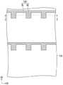
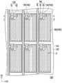
图1A至图1I是依照本发明的第一实施例的一种主动元件阵列基板的制作流程的局部上视示意图,其中图1I省略第二绝缘层,以清楚表示位于第二绝缘层下方的膜层。图2A至图2I分别是图1A至图1I中剖线I-I’的局部剖面示意图。1A to 1I are schematic partial top views of the manufacturing process of an active device array substrate according to the first embodiment of the present invention, wherein the second insulating layer is omitted in FIG. 1I to clearly show the film under the second insulating layer layer. 2A to 2I are partial cross-sectional schematic diagrams of the section line I-I' in FIGS. 1A to 1I, respectively.
请先参照图1I及图2I,主动元件阵列基板100包括基板110、第一图案化金属层120、第一绝缘层130、图案化半导体层140、第一透光导电图案层150、第二图案化金属层160、第二绝缘层170以及第二透光导电图案层180。第一图案化金属层120配置在基板110上。第一绝缘层130位于基板110上且覆盖第一图案化金属层120。在本实施例中,第一绝缘层130还可进一步覆盖被第一图案化金属层120所暴露出的基板110。图案化半导体层140配置于第一绝缘层130上。第一透光导电图案层150配置于第一绝缘层130上且延伸至图案化半导体层140上,并覆盖图案化半导体层140的局部区域。第二图案化金属层160配置于第一透光导电图案层150上,且第二图案化金属层160与第一透光导电图案层150的重叠面积在基板110上的正投影(垂直投影)与第二图案化金属层160在基板110上的正投影一致。第二绝缘层170覆盖第二图案化金属层160、被第二图案化金属层160暴露出的第一透光导电图案层150以及被第一透光导电图案层150暴露出的图案化半导体层140以及第一绝缘层130。第二透光导电图案层180位于第二绝缘层170上且对应于第一透光导电图案层150。具体地,第二透光导电图案层180例如是配置于第二绝缘层170上且与第一透光导电图案层150重叠。Please refer to FIG. 1I and FIG. 2I first, the active
以下以图1A至图2I说明主动元件阵列基板100的一种制作流程,但本发明的主动元件阵列基板不以此为限。首先,请参照图1A及图2A,提供基板110。基板110的材质可为玻璃、石英、有机聚合物或是其他合适的材质。A manufacturing process of the active
在基板110上形成第一图案化金属层120。第一图案化金属层120的材质可包括金属或合金。所述金属例如为钼、铝、钨化钼或钨化铜,但不以此为限。第一图案化金属层120可以是由第一金属层(未显示)图案化形成。第一金属层可以是上述金属或合金所形成的单一膜层或多层堆叠层。A first patterned
在本实施例中,第一图案化金属层120包括多条扫描线SL以及多个栅极GE。各扫描线SL沿第一方向D1延伸,且扫描线SL沿第二方向D2排列,其中第一方向D1与第二方向D2相交且例如是彼此垂直,但不以此为限。各栅极GE与其中一扫描线SL连接,且栅极GE沿第一方向D1间格排列。In this embodiment, the first
请参照图1B及图2B,先在基板110上形成整面的第一绝缘层130,其中第一绝缘层130覆盖第一图案化金属层120以及被第一图案化金属层120暴露出来的基板110。第一绝缘层130可以是有机材料层、无机材料层或上述两个的堆叠层。无机材料层可包括氧化硅层、氮化硅层、氮氧化硅层或上述两个的堆叠层。Referring to FIG. 1B and FIG. 2B , a first insulating
再于第一绝缘层130上形成图案化半导体层140。图案化半导体层140可由半导体层图案化形成,且图案化半导体层140可为非晶硅半导体层或氧化铟镓锌半导体层。在本实施例中,图案化半导体层140包括多个半导体图案CH,且各半导体图案CH位于其中一栅极GE上方。A patterned
请参照图1C及图2C,在基板110上形成第一透光导电层T1。第一透光导电层T1的材质可包括金属氧化物,如铟锡氧化物(Indium Tin Oxide,ITO)或铟锌氧化物(Indium ZincOxide,IZO),但不以此为限。第一透光导电层T1不以单层为限。具体地,第一透光导电层T1可为金属氧化物层或金属氧化物的堆叠层。Referring to FIG. 1C and FIG. 2C , a first light-transmitting conductive layer T1 is formed on the
于第一透光导电层T1上形成第二金属层M2。第二金属层M2的材质可包括金属或合金。所述金属例如可为铜,但不以此为限。第二金属层M2可以是上述金属或合金所形成的单一膜层或多层堆叠层。A second metal layer M2 is formed on the first light-transmitting conductive layer T1. The material of the second metal layer M2 may include metal or alloy. The metal can be copper, for example, but not limited thereto. The second metal layer M2 may be a single film layer or a multilayer stack formed of the above metals or alloys.
由于在形成第二金属层M2时,半导体图案CH已被第一透光导电层T1覆盖住,因此第一透光导电层T1可保护半导体图案CH,避免金属杂质渗入半导体图案CH中而对元件电性造成负面影响。Since the semiconductor pattern CH has been covered by the first light-transmitting conductive layer T1 when the second metal layer M2 is formed, the first light-transmitting conductive layer T1 can protect the semiconductor pattern CH, preventing metal impurities from penetrating into the semiconductor pattern CH and damaging the components. Negative effects on electricity.
请参照图1D及图2D,于第二金属层M2上形成图案化光阻层PR。形成图案化光阻层PR的方法例如是于第二金属层M2上全面形成一光阻层(未显示),再利用灰阶掩膜(未显示)对光阻层进行曝光及显影等步骤。在本实施例中,图案化光阻层PR包括多个第一光阻图案PR1以及多个第二光阻图案PR2,其中第一光阻图案PR1的厚度大于第二光阻图案PR2的厚度。第一光阻图案PR1以及第二光阻图案PR2用以定义后续欲形成的第一透光导电图案层150以及第二图案化金属层160。Referring to FIG. 1D and FIG. 2D , a patterned photoresist layer PR is formed on the second metal layer M2 . The method of forming the patterned photoresist layer PR is, for example, forming a photoresist layer (not shown) on the second metal layer M2, and then using a grayscale mask (not shown) to expose and develop the photoresist layer. In this embodiment, the patterned photoresist layer PR includes a plurality of first photoresist patterns PR1 and a plurality of second photoresist patterns PR2, wherein the thickness of the first photoresist patterns PR1 is greater than the thickness of the second photoresist patterns PR2. The first photoresist pattern PR1 and the second photoresist pattern PR2 are used to define the first transparent
请参照图1E及图2E,以第一光阻图案PR1以及第二光阻图案PR2为罩幕,移除被图案化光阻层PR暴露出的第二金属层M2及其下的第一透光导电层T1,以形成第一透光导电图案层150。移除第二金属层M2及第一透光导电层T1的方法可以是湿式蚀刻。举例而言,若第二金属层M2的材质为铜,且第一透光导电层T1的材质为铟锌氧化物,则蚀刻剂可选用与第二金属层M2反应但不与图案化半导体层140反应的铜酸,以及与第一透光导电层T1反应的草酸。藉由调变铜酸及草酸的蚀刻比,可有效地移除被图案化光阻层PR暴露出的第二金属层M2及其下的第一透光导电层T1,并可将蚀刻剂对于图案化半导体层140的损害降低。依据第二金属层M2及第一透光导电层T1的材质的不同,蚀刻剂的选用及组成亦有所不同,而不限于上述。Referring to FIG. 1E and FIG. 2E , using the first photoresist pattern PR1 and the second photoresist pattern PR2 as a mask, the second metal layer M2 exposed by the patterned photoresist layer PR and the first transparent layer under it are removed. The photoconductive layer T1 to form the first light-transmitting
第一透光导电图案层150可包括多个第一图案152以及多个第二图案154,其中第一图案152由第一光阻图案PR1的第一部分PT1定义而成,且第二图案154由第一光阻图案PR1的第二部分PT2及第二光阻图案PR2定义而成。如图2E所示,第一图案152与第二图案154分别延伸至半导体图案CH上,且覆盖半导体图案CH的局部区域。The first light-transmitting
请参照图1F及图2F,移除第二光阻图案PR2,以暴露出位于第二光阻图案PR2下方的第二金属层M2。移除第二光阻图案PR2的方法可以是干式蚀刻,但不以此为限。Referring to FIG. 1F and FIG. 2F , the second photoresist pattern PR2 is removed to expose the second metal layer M2 under the second photoresist pattern PR2 . The method for removing the second photoresist pattern PR2 may be dry etching, but not limited thereto.
请参照图1G至图1H及图2G至图2H,以第一光阻图案PR1为罩幕,移除被第一光阻图案PR1暴露出的第二金属层M2,以形成第二图案化金属层160。移除第二金属层M2的方法可以是湿式蚀刻。举例而言,若第二金属层M2的材质为铜,则蚀刻剂可选用与第二金属层M2反应但不与图案化半导体层140反应的铜酸,以降低对图案化半导体层140的损害。然而,蚀刻剂的选择不以此为限。1G to FIG. 1H and FIG. 2G to FIG. 2H, the first photoresist pattern PR1 is used as a mask to remove the second metal layer M2 exposed by the first photoresist pattern PR1 to form a second patterned metal layer.
移除第一光阻图案PR1,以暴露出第二图案化金属层160。在本实施例中,第二图案化金属层160包括多条数据线DL、多个源极SE以及多个漏极DE。各数据线DL沿第二方向D2延伸,且数据线DL沿第一方向D1排列。数据线DL与扫描线SL交错以划分出多个子像素区SP(图1H仅示意性标示出一个子像素区SP)。各源极SE位于其中一子像素区SP内且与对应的数据线DL连接,其中各数据线DL与其所连接的源极SE位于其中一第一图案152上,并且第一图案152在基板110上的正投影P152与数据线DL及源极SE在基板110上的正投影PDS一致。所述正投影一致是指正投影完全重叠,且正投影的形状相同而尺寸实质相同。所述尺寸实质相同包括尺寸相同及尺寸近似的情况。具体地,依据选用的蚀刻剂的不同,正投影的尺寸可能相同或略有差异。各第二图案154位于其中一子像素区SP中,且各漏极DE位于其中一第二图案154上,其中漏极DE与第二图案154的重叠面积在基板110上的正投影PA与漏极DE在基板110上的正投影PDE一致。换句话说,第一透光导电图案层150在基板110上的投影面积大于第二图案化金属层160在基板110上的投影面积,且第二图案化金属层160在基板110上的投影面积落在第一透光导电图案层150在基板110上的投影面积所涵盖的范围内。The first photoresist pattern PR1 is removed to expose the second
各漏极DE位于其中一子像素区SP内且与对应的源极SE相对设置。在各子像素区SP中,源极SE覆盖延伸至半导体图案CH上的第一图案152。漏极DE覆盖延伸至半导体图案CH上的第二图案154,且半导体图案CH被第一图案152与第二图案154暴露出来的区域与半导体图案CH被源极SE与漏极DE暴露出来的区域一致。Each drain DE is located in one of the sub-pixel regions SP and opposite to the corresponding source SE. In each sub-pixel region SP, the source electrode SE covers the
由于主动元件阵列基板100可利用一道掩膜(如上述的灰阶掩膜)形成第一透光导电图案层150与第二图案化金属层160,因此相较于现有技术利用两道掩膜形成第一透光导电图案层与第二图案化金属层,本实施例的主动元件阵列基板100可减少制程所需的掩膜数量,从而降低应用主动元件阵列基板100的显示面板的制作成本。Since the active
请参照图1I及图2I,在基板110上形成第二绝缘层170。第二绝缘层170覆盖第二图案化金属层160、被第二图案化金属层160暴露出的第一透光导电图案层150以及被第一透光导电图案层150暴露出的图案化半导体层140以及第一绝缘层130。第二绝缘层170可以是有机材料层、无机材料层或上述两个的堆叠层。无机材料层可包括氧化硅层、氮化硅层、氮氧化硅层或上述两个的堆叠层。Referring to FIG. 1I and FIG. 2I , a second insulating
于第二绝缘层170上形成第二透光导电图案层180。第二透光导电图案层180的材质可包括金属氧化物,如铟锡氧化物或铟锌氧化物,但不以此为限。此外,第二透光导电图案层180不以单层为限。具体地,第二透光导电图案层180可为金属氧化物层或金属氧化物的堆叠层。第二透光导电图案层180可以是于第二绝缘层170上形成第二透光导电层再藉由图案化制程形成。A second transparent
在本实施例中,第二透光导电图案层180包括多个第三图案182,且第三图案182对应第一透光导电图案层150的第二图案154设置。各第三图案182位于其中一子像素区SP中且位于其中一第二图案154上方。以边缘场切换像素结构为例,各第三图案182可具有多个开口O,并且各第三图案182可利用开口O与对应的第二图案154产生电场。In this embodiment, the second light-transmitting
此外,第二图案化金属层160的底角θ1小于第一透光导电图案层150的底角θ2。举例而言,底角θ1的范围是20度~60度,底角θ2的范围是75度~90度。较佳地,底角θ1的范围是30度~40度,底角θ2的范围是85度~90度。第二图案化金属层160底角小、斜边的坡度较缓可让后续制程的膜层(如第二透光导电图案层180)不易断开,而第一透光导电图案层150的底角大除了可避免在斜坡处产生暗纹外,在晶体管元件的通道区也可维持通道长度,稳定电性。In addition, the bottom angle θ1 of the second
在本实施例中,各子像素区SP配置有其中一栅极GE、其中一半导体图案CH、其中一第一图案152、其中一第二图案154、其中一源极SE、其中一漏极DE以及其中一第三图案182。此外,各子像素区SP的形状为矩形。然而,各子像素区SP的形状及各子像素区SP中各元件的数量、各元件的形状及元件间的相对配置关系可视需求改变,而不限于图1I及图2I的显示。In this embodiment, each sub-pixel region SP is configured with one of the gate GE, one of the semiconductor pattern CH, one of the
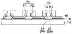
图3是依照本发明的第二实施例的一种主动元件阵列基板的局部剖面示意图。请参照图3,主动元件阵列基板200除了基板110、第一图案化金属层120、第一绝缘层130、图案化半导体层140、第一透光导电图案层150、第二图案化金属层160、第二绝缘层170以及第二透光导电图案层180之外,可进一步包括第三绝缘层210,以保护图案化半导体层140。举例而言,第三绝缘层210可以是无机材料层。无机材料层可包括氧化硅层、氮化硅层、氮氧化硅层或上述两个的堆叠层。FIG. 3 is a schematic partial cross-sectional view of an active device array substrate according to a second embodiment of the present invention. Please refer to FIG. 3 , the active
第三绝缘层210设置于图案化半导体层140与第一透光导电图案层150间。第三绝缘层210具有多个第一开口O1以及多个第二开口O2(仅示意性显示出一个第一开口O1以及一个第二开口O2)。第一开口O1对应源极SE设置且分别暴露出各半导体图案CH的一部分区域。第二开口O2对应漏极DE设置且分别暴露出各半导体图案CH的另一部分区域。第一透光导电图案层150配置于第三绝缘层210上,且各第一图案152通过其中一第一开口O1与对应的半导体图案CH接触,而各第二图案154通过其中一第二开口O2与对应的半导体图案CH接触。The third
在本实施例中,主动元件阵列基板200亦可利用一道掩膜形成第一透光导电图案层150与第二图案化金属层160。因此,相较于现有技术藉由两道掩膜形成第一透光导电图案层与第二图案化金属层,本实施例的主动元件阵列基板200可减少所需的掩膜数量,从而降低应用主动元件阵列基板200的显示面板的制作成本。In this embodiment, the active
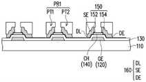
图4是依照本发明的一实施例的一种显示面板的局部剖面示意图。请参照图4,显示面板10包括主动元件阵列基板12、对向基板14以及显示介质层16。主动元件阵列基板12例如采用图2I所显示的主动元件阵列基板100,但不以此为限。在另一实施例中,主动元件阵列基板12可采用图3所显示的主动元件阵列基板200。对向基板14相对于主动元件阵列基板12。显示介质层16位于主动元件阵列基板12与对向基板14之间。FIG. 4 is a schematic partial cross-sectional view of a display panel according to an embodiment of the present invention. Referring to FIG. 4 , the
对向基板14的材质可为玻璃、石英、有机聚合物或是其他合适的材质。显示介质层16可为液晶层。藉由调变第二图案154与第三图案182之间的电压差值,可控制液晶层中液晶分子的转向,从而调控显示画面的灰阶值。The material of the
依据不同的设计需求,显示面板10可进一步包括其他膜层。举例而言,显示面板10可进一步包括黑矩阵层BM,以遮蔽显示面板10中不欲被看见的元件,如图1I中的扫描线SL、数据线DL、主动元件(由栅极GE、半导体图案CH、源极SE以及漏极DE所构成)或其他未显示的线路。此外,显示面板10也可进一步包括彩色滤光层CF,以提供彩色的显示画面。According to different design requirements, the
综上所述,本发明实施例可利用一道掩膜形成第一透光导电图案层与第二图案化金属层。相较于现有技术藉由两道掩膜形成第一透光导电图案层与第二图案化金属层,本发明实施例的主动元件阵列基板可减少所需的掩膜数量,从而可降低应用此主动元件阵列基板的显示面板的制作成本。In summary, the embodiment of the present invention can use one mask to form the first light-transmitting conductive pattern layer and the second patterned metal layer. Compared with the prior art that uses two masks to form the first light-transmitting conductive pattern layer and the second patterned metal layer, the active device array substrate of the embodiment of the present invention can reduce the number of masks required, thereby reducing the application cost. The manufacturing cost of the display panel of the active element array substrate.
虽然本发明已以实施例揭示如上,然其并非用以限定本发明,任何所属技术领域中普通技术人员,在不脱离本发明的精神和范围内,当可作些许的改动与润饰,故本发明的保护范围当视所附权利要求界定范围为准。Although the present invention has been disclosed above with the embodiments, it is not intended to limit the present invention. Any person skilled in the art can make some changes and modifications without departing from the spirit and scope of the present invention. Therefore, this The scope of protection of the invention should be determined by the appended claims.
Claims (8)
Priority Applications (1)
| Application Number | Priority Date | Filing Date | Title |
|---|---|---|---|
| CN202110555994.3ACN113219749B (en) | 2016-02-17 | 2016-02-17 | Active element array substrate and display panel |
Applications Claiming Priority (2)
| Application Number | Priority Date | Filing Date | Title |
|---|---|---|---|
| CN201610088989.5ACN107092111B (en) | 2016-02-17 | 2016-02-17 | Active element array substrate and display panel |
| CN202110555994.3ACN113219749B (en) | 2016-02-17 | 2016-02-17 | Active element array substrate and display panel |
Related Parent Applications (1)
| Application Number | Title | Priority Date | Filing Date |
|---|---|---|---|
| CN201610088989.5ADivisionCN107092111B (en) | 2016-02-17 | 2016-02-17 | Active element array substrate and display panel |
Publications (2)
| Publication Number | Publication Date |
|---|---|
| CN113219749A CN113219749A (en) | 2021-08-06 |
| CN113219749Btrue CN113219749B (en) | 2023-01-10 |
Family
ID=59561453
Family Applications (2)
| Application Number | Title | Priority Date | Filing Date |
|---|---|---|---|
| CN201610088989.5AActiveCN107092111B (en) | 2016-02-17 | 2016-02-17 | Active element array substrate and display panel |
| CN202110555994.3AActiveCN113219749B (en) | 2016-02-17 | 2016-02-17 | Active element array substrate and display panel |
Family Applications Before (1)
| Application Number | Title | Priority Date | Filing Date |
|---|---|---|---|
| CN201610088989.5AActiveCN107092111B (en) | 2016-02-17 | 2016-02-17 | Active element array substrate and display panel |
Country Status (2)
| Country | Link |
|---|---|
| US (1) | US10203577B2 (en) |
| CN (2) | CN107092111B (en) |
Families Citing this family (3)
| Publication number | Priority date | Publication date | Assignee | Title |
|---|---|---|---|---|
| US11830833B2 (en)* | 2020-07-24 | 2023-11-28 | Innolux Corporation | Electronic substrate and electronic device |
| CN113435382B (en)* | 2020-08-17 | 2023-04-18 | 友达光电股份有限公司 | Sensing device |
| TWI750838B (en)* | 2020-10-08 | 2021-12-21 | 友達光電股份有限公司 | Display panel and method for manufacturing the same |
Citations (13)
| Publication number | Priority date | Publication date | Assignee | Title |
|---|---|---|---|---|
| US5668379A (en)* | 1994-07-27 | 1997-09-16 | Hitachi, Ltd. | Active matrix crystal display apparatus using thin film transistor |
| JP2001281698A (en)* | 2000-03-30 | 2001-10-10 | Advanced Display Inc | Production method for optoelectronic element |
| CN1700443A (en)* | 2004-04-28 | 2005-11-23 | 株式会社半导体能源研究所 | Wiring on substrate, semiconductor device, and manufacturing method thereof |
| KR20070070719A (en)* | 2005-12-29 | 2007-07-04 | 엘지.필립스 엘시디 주식회사 | Method for manufacturing thin film transistor array substrate and thin film transistor array substrate using same |
| CN101043025A (en)* | 2006-03-22 | 2007-09-26 | 群康科技(深圳)有限公司 | Method for manufacturing thin-film transistor substrates |
| CN101097320A (en)* | 2006-06-29 | 2008-01-02 | Lg.菲利浦Lcd株式会社 | Liquid crystal display device and manufacturing method thereof |
| CN101132011A (en)* | 2006-07-20 | 2008-02-27 | 三星电子株式会社 | Array substrate, manufacturing method thereof, and display device having array substrate |
| CN101685229A (en)* | 2008-09-25 | 2010-03-31 | 北京京东方光电科技有限公司 | Method for manufacturing array substrate of liquid crystal display device |
| CN101887897A (en)* | 2009-05-13 | 2010-11-17 | 北京京东方光电科技有限公司 | TFT-LCD array substrate and manufacturing method thereof |
| CN102468340A (en)* | 2010-11-17 | 2012-05-23 | 奇美电子股份有限公司 | Thin film transistor and forming method thereof |
| CN102566179A (en)* | 2010-11-26 | 2012-07-11 | 乐金显示有限公司 | Method for fabricating liquid crystal display device |
| CN104008999A (en)* | 2014-05-26 | 2014-08-27 | 昆山国显光电有限公司 | Thin film transistor array member, manufacturing method thereof and array substrate |
| CN104678664A (en)* | 2013-11-29 | 2015-06-03 | 乐金显示有限公司 | Liquid crystal display and method for manufacturing the same |
Family Cites Families (18)
| Publication number | Priority date | Publication date | Assignee | Title |
|---|---|---|---|---|
| CN1333432C (en)* | 2003-08-21 | 2007-08-22 | 广辉电子股份有限公司 | Manufacturing method of thin film transistor array substrate |
| TWI284246B (en)* | 2004-08-13 | 2007-07-21 | Au Optronics Corp | Pixel structure of a liquid crystal display and fabricating method thereof and liquid crystal display panel |
| KR101085132B1 (en)* | 2004-12-24 | 2011-11-18 | 엘지디스플레이 주식회사 | Horizontal field thin film transistor substrate and its manufacturing method |
| KR20060133818A (en)* | 2005-06-21 | 2006-12-27 | 삼성전자주식회사 | Method for manufacturing photomask and thin film transistor substrate and thin film transistor substrate manufactured by |
| CN100499082C (en)* | 2005-11-10 | 2009-06-10 | 群康科技(深圳)有限公司 | Thin-film transistor substrate and its manufacture method |
| JP2007310334A (en)* | 2006-05-19 | 2007-11-29 | Mikuni Denshi Kk | Manufacturing method of liquid crystal display device using halftone exposure method |
| KR101241129B1 (en)* | 2006-06-28 | 2013-03-08 | 엘지디스플레이 주식회사 | Array substrate for liquid crystal display device and method of fabricating the same |
| KR101266275B1 (en)* | 2006-06-30 | 2013-05-22 | 엘지디스플레이 주식회사 | Method of fabricating liquid crystal display device |
| KR100978264B1 (en)* | 2006-12-26 | 2010-08-26 | 엘지디스플레이 주식회사 | Reflective type liquid crystal display device and manufacturing method |
| KR101294232B1 (en)* | 2007-06-08 | 2013-08-07 | 엘지디스플레이 주식회사 | Fringe field switching mode liquid crystal display device and the method for fabricating the same |
| TWI382253B (en)* | 2008-02-04 | 2013-01-11 | Au Optronics Corp | Active array substrate, liquid crystal display panel, and manufacturing method thereof |
| CN103270601B (en)* | 2010-12-20 | 2016-02-24 | 夏普株式会社 | Semiconductor device and display unit |
| CN102569185A (en)* | 2010-12-22 | 2012-07-11 | 京东方科技集团股份有限公司 | Array substrate, production method thereof and liquid crystal display |
| CN102683277A (en)* | 2012-05-08 | 2012-09-19 | 深圳市华星光电技术有限公司 | Thin film transistor array substrate and making method thereof |
| CN103149760B (en)* | 2013-02-19 | 2015-03-11 | 合肥京东方光电科技有限公司 | Thin film transistor array substrate, manufacturing method and display device |
| KR20140137922A (en)* | 2013-05-24 | 2014-12-03 | 삼성디스플레이 주식회사 | Array substrate and method of manufacturing the same |
| CN104425545B (en)* | 2013-09-10 | 2017-12-08 | 群创光电股份有限公司 | Display device |
| CN203941365U (en)* | 2014-07-09 | 2014-11-12 | 京东方科技集团股份有限公司 | Array base palte, display panel and display device |
- 2016
- 2016-02-17CNCN201610088989.5Apatent/CN107092111B/enactiveActive
- 2016-02-17CNCN202110555994.3Apatent/CN113219749B/enactiveActive
- 2017
- 2017-02-16USUS15/434,070patent/US10203577B2/enactiveActive
Patent Citations (13)
| Publication number | Priority date | Publication date | Assignee | Title |
|---|---|---|---|---|
| US5668379A (en)* | 1994-07-27 | 1997-09-16 | Hitachi, Ltd. | Active matrix crystal display apparatus using thin film transistor |
| JP2001281698A (en)* | 2000-03-30 | 2001-10-10 | Advanced Display Inc | Production method for optoelectronic element |
| CN1700443A (en)* | 2004-04-28 | 2005-11-23 | 株式会社半导体能源研究所 | Wiring on substrate, semiconductor device, and manufacturing method thereof |
| KR20070070719A (en)* | 2005-12-29 | 2007-07-04 | 엘지.필립스 엘시디 주식회사 | Method for manufacturing thin film transistor array substrate and thin film transistor array substrate using same |
| CN101043025A (en)* | 2006-03-22 | 2007-09-26 | 群康科技(深圳)有限公司 | Method for manufacturing thin-film transistor substrates |
| CN101097320A (en)* | 2006-06-29 | 2008-01-02 | Lg.菲利浦Lcd株式会社 | Liquid crystal display device and manufacturing method thereof |
| CN101132011A (en)* | 2006-07-20 | 2008-02-27 | 三星电子株式会社 | Array substrate, manufacturing method thereof, and display device having array substrate |
| CN101685229A (en)* | 2008-09-25 | 2010-03-31 | 北京京东方光电科技有限公司 | Method for manufacturing array substrate of liquid crystal display device |
| CN101887897A (en)* | 2009-05-13 | 2010-11-17 | 北京京东方光电科技有限公司 | TFT-LCD array substrate and manufacturing method thereof |
| CN102468340A (en)* | 2010-11-17 | 2012-05-23 | 奇美电子股份有限公司 | Thin film transistor and forming method thereof |
| CN102566179A (en)* | 2010-11-26 | 2012-07-11 | 乐金显示有限公司 | Method for fabricating liquid crystal display device |
| CN104678664A (en)* | 2013-11-29 | 2015-06-03 | 乐金显示有限公司 | Liquid crystal display and method for manufacturing the same |
| CN104008999A (en)* | 2014-05-26 | 2014-08-27 | 昆山国显光电有限公司 | Thin film transistor array member, manufacturing method thereof and array substrate |
Non-Patent Citations (2)
| Title |
|---|
| Extreme bending test of IGZO TFT;Sejin Hong;《 2014 21st International Workshop on Active-Matrix Flatpanel Displays and Devices》;20141231;1-3* |
| 图案化铜纳米线阵列的制备;刘曦等;《电子元件与材料》;20081205(第12期);55-57* |
Also Published As
| Publication number | Publication date |
|---|---|
| US10203577B2 (en) | 2019-02-12 |
| US20170235172A1 (en) | 2017-08-17 |
| CN107092111A (en) | 2017-08-25 |
| CN107092111B (en) | 2021-06-11 |
| CN113219749A (en) | 2021-08-06 |
Similar Documents
| Publication | Publication Date | Title |
|---|---|---|
| CN103681693B (en) | Array substrate, manufacturing method of array substrate and display device | |
| US9711542B2 (en) | Method for fabricating display panel | |
| US10056414B2 (en) | Thin film transistor array substrate having black matrix formed in non-display zone and common electrode formed in display zone | |
| CN101598876B (en) | Array substrate for liquid crystal display device and method of fabricating the same | |
| CN102236227B (en) | Liquid crystal display device and manufacturing method thereof | |
| KR101900170B1 (en) | Method for manufacturing array substrate, array substrate and display device | |
| CN102466934A (en) | High light transmittance in-plane switching liquid crystal display device and method for manufacturing the same | |
| TW201418855A (en) | Array substrate of display panel and manufacturing method thereof | |
| CN103117248B (en) | Array substrate and manufacture method thereof and display device | |
| CN103035652B (en) | Array substrate of fringe field switching type liquid crystal display panel and method of fabricating the same | |
| CN113219749B (en) | Active element array substrate and display panel | |
| CN104020621B (en) | A kind of array base palte and preparation method thereof, display device | |
| KR101320651B1 (en) | Method of Fabricating Liquid Crystal Display Panel Of Horizontal Electronic Fileld Applying Type | |
| CN103219341B (en) | A kind of array base palte and preparation method, display device | |
| CN104216190B (en) | Array base palte and preparation method thereof, display device | |
| US9383608B2 (en) | Array substrate and manufacturing method thereof | |
| TWI460515B (en) | Array substrate of fringe field switching mode liquid crystal display panel and method of manufacturing the same | |
| TWI417966B (en) | Pixel structure manufacturing method | |
| US20160033754A1 (en) | Display device and method for fabricating the same | |
| CN106873274A (en) | Pixel structure | |
| CN102244035B (en) | Pixel structure and its manufacturing method | |
| US8603844B2 (en) | Pixel structure and manufacturing method thereof | |
| KR101385244B1 (en) | Array substrate for liquid crystal display and method for fabricating the same | |
| KR20080070320A (en) | Display substrate and manufacturing method thereof | |
| TW201316104A (en) | Pixel structure of display panel and manufacturing method thereof |
Legal Events
| Date | Code | Title | Description |
|---|---|---|---|
| PB01 | Publication | ||
| PB01 | Publication | ||
| SE01 | Entry into force of request for substantive examination | ||
| SE01 | Entry into force of request for substantive examination | ||
| GR01 | Patent grant | ||
| GR01 | Patent grant |