CN113219665B - Optical lens group, optical system and head-mounted display device - Google Patents
Optical lens group, optical system and head-mounted display deviceDownload PDFInfo
- Publication number
- CN113219665B CN113219665BCN202110489112.8ACN202110489112ACN113219665BCN 113219665 BCN113219665 BCN 113219665BCN 202110489112 ACN202110489112 ACN 202110489112ACN 113219665 BCN113219665 BCN 113219665B
- Authority
- CN
- China
- Prior art keywords
- light
- polarization
- polarization state
- region
- optical lens
- Prior art date
- Legal status (The legal status is an assumption and is not a legal conclusion. Google has not performed a legal analysis and makes no representation as to the accuracy of the status listed.)
- Active
Links
Images


Classifications
- G—PHYSICS
- G02—OPTICS
- G02B—OPTICAL ELEMENTS, SYSTEMS OR APPARATUS
- G02B27/00—Optical systems or apparatus not provided for by any of the groups G02B1/00 - G02B26/00, G02B30/00
- G02B27/01—Head-up displays
- G02B27/017—Head mounted
- G02B27/0172—Head mounted characterised by optical features
- G—PHYSICS
- G02—OPTICS
- G02B—OPTICAL ELEMENTS, SYSTEMS OR APPARATUS
- G02B27/00—Optical systems or apparatus not provided for by any of the groups G02B1/00 - G02B26/00, G02B30/00
- G02B27/28—Optical systems or apparatus not provided for by any of the groups G02B1/00 - G02B26/00, G02B30/00 for polarising
- G02B27/283—Optical systems or apparatus not provided for by any of the groups G02B1/00 - G02B26/00, G02B30/00 for polarising used for beam splitting or combining
- G—PHYSICS
- G02—OPTICS
- G02B—OPTICAL ELEMENTS, SYSTEMS OR APPARATUS
- G02B27/00—Optical systems or apparatus not provided for by any of the groups G02B1/00 - G02B26/00, G02B30/00
- G02B27/28—Optical systems or apparatus not provided for by any of the groups G02B1/00 - G02B26/00, G02B30/00 for polarising
- G02B27/286—Optical systems or apparatus not provided for by any of the groups G02B1/00 - G02B26/00, G02B30/00 for polarising for controlling or changing the state of polarisation, e.g. transforming one polarisation state into another
Landscapes
- Physics & Mathematics (AREA)
- General Physics & Mathematics (AREA)
- Optics & Photonics (AREA)
Abstract
Description
Translated fromChinese技术领域technical field
本发明涉及光学显示技术领域,尤其涉及一种光学镜组、光学系统和头戴显示设备。The present invention relates to the technical field of optical display, in particular to an optical lens group, an optical system and a head-mounted display device.
背景技术Background technique
头戴显示(Head mounted display)设备是一种能够提供身临其境体验的电子产品,目前头戴显示设备的显示原理包括虚拟现实(Virtual Reality)技术、增强现实(Augmented Reality)技术以及混合现实(Mixed Reality)技术。Head mounted display (Head mounted display) device is an electronic product that can provide an immersive experience. Currently, the display principles of head mounted display devices include virtual reality (Virtual Reality) technology, augmented reality (Augmented Reality) technology and mixed reality (Mixed Reality) technology.
而头戴显示设备需要将光线准确的在人眼位置成像显示,光线需要经过足够的光程,为此头戴显示设备需要有足够的光路传播空间,由此导致头戴显示设备的体积较大,不便于用户使用穿戴。The head-mounted display device needs to accurately display the light at the position of the human eye, and the light needs to pass through a sufficient optical path. Therefore, the head-mounted display device needs to have enough light path propagation space, which leads to a larger volume of the head-mounted display device. , it is not convenient for users to use and wear.
发明内容Contents of the invention
基于此,针对现有头戴显示设备的体积较大,不便于用户使用穿戴的问题,有必要提供一种光学镜组、光学系统和头戴显示设备,旨在减小头戴显示设备的体积,方便用户使用穿戴。Based on this, in order to solve the problem that the existing head-mounted display device is relatively large and inconvenient for users to use and wear, it is necessary to provide an optical lens group, an optical system and a head-mounted display device, aiming at reducing the volume of the head-mounted display device , convenient for users to use and wear.
为实现上述目的,本发明提出的一种光学镜组,所述光学镜组包括:In order to achieve the above object, the present invention proposes an optical mirror group, the optical mirror group includes:
透镜本体,所述透镜本体包括光线入射的入光面和光线出射的出光面;A lens body, the lens body includes a light-incident surface on which light is incident and a light-exit surface on which light is emitted;
半反半透膜,所述半反半透膜设于所述入光面;a semi-reflective and semi-permeable film, the semi-reflective and semi-permeable film is arranged on the light incident surface;
偏振转换器件,所述偏振转换器件设于所述出光面;以及a polarization conversion device, the polarization conversion device is arranged on the light-emitting surface; and
偏振反射器件,所述偏振反射器件设于所述偏振转换器件背离所述透镜本体的一侧,所述偏振反射器件包括第一偏振反射件和第二偏振反射件,所述第一偏振反射件和所述第二偏振反射件沿光线的传播方向依次设置;A polarized reflective device, the polarized reflective device is arranged on the side of the polarization conversion device away from the lens body, the polarized reflective device includes a first polarized reflective element and a second polarized reflective element, the first polarized reflective element and the second polarizing reflector are sequentially arranged along the propagation direction of the light;
光线在经过所述偏振转换器件后具有第一偏振态或第二偏振态,所述第一偏振反射件的表面包括第一区域和第二区域,所述第一区域透射第一偏振态的光线,所述第二区域反射第一偏振态的光线,并透射第二偏振态的光线,所述第二偏振反射件反射第二偏振态的光线,并透射第一偏振态的光线。The light has a first polarization state or a second polarization state after passing through the polarization conversion device, the surface of the first polarization reflection member includes a first region and a second region, and the first region transmits the light of the first polarization state , the second region reflects the light of the first polarization state and transmits the light of the second polarization state, and the second polarized reflector reflects the light of the second polarization state and transmits the light of the first polarization state.
可选地,所述第一区域设有若干,所述第二区域设有若干,所述第一区域与所述第二区域分布于所述第一偏振反射件的表面。Optionally, there are several first regions and several second regions, and the first regions and the second regions are distributed on the surface of the first polarizing reflector.
可选地,所述第一区域和所述第二区域依次交替排列。Optionally, the first regions and the second regions are arranged alternately in sequence.
可选地,所述第一区域和/或所述第二区域均匀的分布于所述第一偏振反射件的表面。Optionally, the first region and/or the second region are uniformly distributed on the surface of the first polarizing reflector.
可选地,所述第一区域占据的面积与所述第二区域占据的面积相同。Optionally, the area occupied by the first region is the same as the area occupied by the second region.
可选地,所述第一区域和所述第二区域为方形。Optionally, the first area and the second area are square.
可选地,所述偏振转换器件为四分之一波片,所述第一偏振反射件和所述第二偏振反射件均为偏振反射膜层。Optionally, the polarization conversion device is a quarter-wave plate, and both the first polarized reflective member and the second polarized reflective member are polarized reflective film layers.
可选地,所述光学镜组还包括杂散光消除件,所述杂散光消除件设于所述偏振反射器件背离所述透镜本体的一侧。Optionally, the optical lens group further includes a stray light eliminating member, and the stray light eliminating member is arranged on a side of the polarized reflection device away from the lens body.
可选地,所述杂散光消除件为偏振片,所述偏振片具有透射方向,所述偏振片的透射方向与第一偏振态的光线振动方向相同。Optionally, the stray light eliminating element is a polarizer, and the polarizer has a transmission direction, and the transmission direction of the polarizer is the same as the vibration direction of light in the first polarization state.
此外,为了实现上述目的,本发明还提供一种光学系统,所述光学系统包括显示器和如上文所述的光学镜组,所述显示器发射光线,所述光学镜组接收所述显示器发射的光线,所述光学系统的总长度小于6mm。In addition, in order to achieve the above object, the present invention also provides an optical system, the optical system includes a display and the above-mentioned optical mirror group, the display emits light, and the optical mirror group receives the light emitted by the display , the total length of the optical system is less than 6mm.
可选地,所述光学系统还包括四分之一波片,所述四分之一波片设于所述显示器的出光面。Optionally, the optical system further includes a quarter-wave plate, and the quarter-wave plate is disposed on the light-emitting surface of the display.
此外,为了实现上述目的,本发明还提供一种头戴显示设备,所述头戴显示设备包括外壳和如上文所述光学镜组,所述光学镜组设于所述外壳。In addition, in order to achieve the above object, the present invention also provides a head-mounted display device, the head-mounted display device includes a casing and the above-mentioned optical mirror group, and the optical mirror group is arranged on the casing.
本发明提出的技术方案中,光线射向成透镜本体时,光线首先经过半反半透膜,一部分光线反射,另一部分光线透射。透射半反半透膜的光线穿过透镜本体。光线射向偏振转换器件,光线的偏振状态转换为第一偏振态,第一偏振态的光线射向第一偏振反射件。在第一偏振反射件的第二区域第一偏振态的光线反射。反射的第一偏振态的光线射向半反半透膜,在半反半透膜的作用下,发生透射和反射现象,反射的光线再次射向偏振转换器件,光线的偏振状态转换为第二偏振态。第二偏振态的光线在第一偏振反射件的第一区域和第二区域均发生透射,透射的第二偏振态的光线射向第二偏振反射件。由于第二偏振反射件反射第二偏振态的光线,并透射第一偏振态的光线,因此,在第二偏振态的光线在射向第二偏振反射件时发生反射。反射的第二偏振态光线透射第一偏振反射件和偏振转换器件,经过半反半透膜时再次发生反射,反射的光线再次经过偏振转换器件时,第二偏振态的光线转化为第一偏振态,第一偏振态的光线在经过第一偏振反射的第一区域时透射,经过第二偏振反射件也发生透射,由此,透射的第一偏振态的光线在人眼位置显示成像。在第一偏振反射件和第二偏振反射件的作用下,光线发生了两次折反射,从而在较小的范围内满足了光程要求,进而缩小了头戴显示设备的体积,方便用户使用穿戴。In the technical solution proposed by the present invention, when the light irradiates to the lens body, the light first passes through the semi-reflective and semi-permeable film, part of the light is reflected, and the other part of the light is transmitted. The light transmitted through the semi-reflective and semi-permeable film passes through the lens body. The light is incident on the polarization conversion device, the polarization state of the light is converted into a first polarization state, and the light in the first polarization state is incident on the first polarization reflector. The light of the first polarization state is reflected in the second region of the first polarizing reflector. The reflected light of the first polarization state goes to the transflective film, under the action of the semi-transparent film, the phenomenon of transmission and reflection occurs, and the reflected light goes to the polarization conversion device again, and the polarization state of the light is converted to the second polarization state. polarization state. The light of the second polarization state is transmitted in both the first region and the second region of the first polarized reflective member, and the transmitted light of the second polarized state is directed toward the second polarized reflective member. Since the second polarized reflection member reflects the light of the second polarization state and transmits the light of the first polarization state, the light of the second polarization state is reflected when it hits the second polarization reflection member. The reflected light of the second polarization state is transmitted through the first polarization reflector and the polarization conversion device, and is reflected again when passing through the semi-reflective and semi-transparent film. When the reflected light passes through the polarization conversion device again, the light of the second polarization state is converted into the first polarization The light of the first polarization state is transmitted when passing through the first region reflected by the first polarization, and is also transmitted through the second polarization reflection member, so that the transmitted light of the first polarization state displays an image at the position of the human eye. Under the action of the first polarizing reflector and the second polarizing reflector, the light is refracted and reflected twice, thus meeting the optical path requirement within a small range, thereby reducing the volume of the head-mounted display device and making it convenient for users to use wear.
附图说明Description of drawings
为了更清楚地说明本发明实施例或现有技术中的技术方案,下面将对实施例或现有技术描述中所需要使用的附图作简单地介绍,显而易见地,下面描述中的附图仅仅是本发明的一些实施例,对于本领域普通技术人员来讲,在不付出创造性劳动的前提下,还可以根据这些附图示出的结构获得其他的附图。In order to more clearly illustrate the technical solutions in the embodiments of the present invention or the prior art, the following will briefly introduce the drawings that need to be used in the description of the embodiments or the prior art. Obviously, the accompanying drawings in the following description are only These are some embodiments of the present invention. For those skilled in the art, other drawings can also be obtained according to the structures shown in these drawings without creative effort.
图1为本发明光学镜组的结构示意图;Fig. 1 is the structural representation of optical lens group of the present invention;
图2为图1中光学镜组的出光面的光学器件的结构示意图;Fig. 2 is a schematic structural view of the optical device on the light exit surface of the optical mirror group in Fig. 1;
图3为图2中第一偏振反射件的结构示意图;Fig. 3 is a schematic structural view of the first polarized reflector in Fig. 2;
图4为本发明光学镜组的调制传递函数图;Fig. 4 is the modulation transfer function diagram of the optical lens group of the present invention;
图5为本发明光学镜组的点列图;Fig. 5 is a spot diagram of the optical lens group of the present invention;
图6为本发明光学镜组的场曲与畸变图;Fig. 6 is a field curvature and distortion diagram of the optical lens group of the present invention;
图7为本发明光学镜组的色差图;Fig. 7 is a chromatic aberration diagram of the optical lens group of the present invention;
图8为本发明光学镜组的相对照度图。Fig. 8 is a relative illuminance diagram of the optical mirror assembly of the present invention.
附图标号说明:Explanation of reference numbers:
本发明目的的实现、功能特点及优点将结合实施例,参照附图做进一步说明。The realization of the purpose of the present invention, functional characteristics and advantages will be further described in conjunction with the embodiments and with reference to the accompanying drawings.
具体实施方式Detailed ways
下面将结合本发明实施例中的附图,对本发明实施例中的技术方案进行清楚、完整地描述,显然,所描述的实施例仅仅是本发明的一部分实施例,而不是全部的实施例。基于本发明中的实施例,本领域普通技术人员在没有作出创造性劳动前提下所获得的所有其他实施例,都属于本发明保护的范围。The following will clearly and completely describe the technical solutions in the embodiments of the present invention with reference to the accompanying drawings in the embodiments of the present invention. Obviously, the described embodiments are only part of the embodiments of the present invention, not all of them. Based on the embodiments of the present invention, all other embodiments obtained by persons of ordinary skill in the art without creative efforts fall within the protection scope of the present invention.
需要说明,本发明实施例中所有方向性指示(诸如上、下、左、右、前、后……)仅用于解释在某一特定姿态(如附图所示)下各部件之间的相对位置关系、运动情况等,如果该特定姿态发生改变时,则该方向性指示也相应地随之改变。It should be noted that all directional indications (such as up, down, left, right, front, back...) in the embodiments of the present invention are only used to explain the relationship between the components in a certain posture (as shown in the figure). Relative positional relationship, movement conditions, etc., if the specific posture changes, the directional indication will also change accordingly.
另外,在本发明中如涉及“第一”、“第二”等的描述仅用于描述目的,而不能理解为指示或暗示其相对重要性或者隐含指明所指示的技术特征的数量。由此,限定有“第一”、“第二”的特征可以明示或者隐含地包括至少一个该特征。在本发明的描述中,“多个”的含义是至少两个,例如两个,三个等,除非另有明确具体的限定。In addition, in the present invention, descriptions such as "first", "second" and so on are used for description purposes only, and should not be understood as indicating or implying their relative importance or implicitly indicating the quantity of indicated technical features. Thus, the features defined as "first" and "second" may explicitly or implicitly include at least one of these features. In the description of the present invention, "plurality" means at least two, such as two, three, etc., unless otherwise specifically defined.
在本发明中,除非另有明确的规定和限定,术语“连接”、“固定”等应做广义理解,例如,“固定”可以是固定连接,也可以是可拆卸连接,或成一体;可以是机械连接,也可以是电连接;可以是直接相连,也可以通过中间媒介间接相连,可以是两个元件内部的连通或两个元件的相互作用关系,除非另有明确的限定。对于本领域的普通技术人员而言,可以根据具体情况理解上述术语在本发明中的具体含义。In the present invention, unless otherwise specified and limited, the terms "connection" and "fixation" should be understood in a broad sense, for example, "fixation" can be a fixed connection, a detachable connection, or an integral body; It can be a mechanical connection or an electrical connection; it can be a direct connection or an indirect connection through an intermediary, and it can be an internal communication between two elements or an interaction relationship between two elements, unless otherwise clearly defined. Those of ordinary skill in the art can understand the specific meanings of the above terms in the present invention according to specific situations.
另外,本发明各个实施例之间的技术方案可以相互结合,但是必须是以本领域普通技术人员能够实现为基础,当技术方案的结合出现相互矛盾或无法实现时应当认为这种技术方案的结合不存在,也不在本发明要求的保护范围之内。In addition, the technical solutions of the various embodiments of the present invention can be combined with each other, but it must be based on the realization of those skilled in the art. When the combination of technical solutions is contradictory or cannot be realized, it should be considered as a combination of technical solutions. Does not exist, nor is it within the scope of protection required by the present invention.
在相关头戴显示的技术领域中,光线需要经过足够的光程,通过足够的光程,光线经过传递后,在人眼位置显示成像。但是光线的传递需要足够的空间来满足光程距离,为此导致头戴显示设备的体积较大,用户在穿戴的过程中十分不便。In the technical field of related head-mounted displays, light needs to pass through a sufficient optical path, and after passing through a sufficient optical path, the light is displayed and imaged at the position of the human eye. However, the transmission of light requires sufficient space to meet the optical distance, which leads to a large volume of the head-mounted display device, which is very inconvenient for the user to wear.
为了解决上述问题,参阅图1至图3所示,本发明提供一种光学镜组,所述光学镜组包括:透镜本体10、半反半透膜20和偏振转换器件30,透镜本体10包括光线入射的入光面110和光线出射的出光面120,透镜本体10可以是单个镜片,也可以是多个镜片组成的镜片组。半反半透膜20设于入光面110,偏振转换器件30设于出光面120;半反半透膜20可以采用镀膜的方式设置在入光面110,也可以采用粘贴的方式设置在入光面110。同样地,偏振转换器件30也可以采用粘贴的方式设置在出光面120。其中,透镜本体10材料可以是透明的玻璃材料,也可以是透明的树脂材料。玻璃材料具有更好的光学特性,例如,更好的透射性能,保证光线的传递数量。树脂材料易于加工,通过热塑成型的方式就可以获得透镜本体10。In order to solve the above problems, as shown in FIGS. 1 to 3 , the present invention provides an optical lens group, which includes: a
光学镜组包括偏振反射器件40,偏振反射器件40设于偏振转换器件30背离透镜本体10的一侧,偏振反射器件40包括第一偏振反射件410和第二偏振反射件420,第一偏振反射件410和第二偏振反射件420沿光线的传播方向依次设置。同样地,第一偏振反射件410和第二偏振反射件420也可以采用粘贴的方式设置在透镜本体10的出光面120的一侧。The optical mirror group includes a polarized
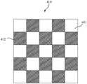
光线在经过偏振转换器件30后具有第一偏振态或第二偏振态,第一偏振反射件410的表面包括第一区域411和第二区域412,第一区域411透射第一偏振态的光线,第二区域412反射第一偏振态的光线,并透射第二偏振态的光线,第二偏振反射件420反射第二偏振态的光线,并透射第一偏振态的光线。例如,第一偏振态为S偏振光,简称S光。第二偏振态为P偏振光,简称P光。S光经过第一偏振反射件410时,第二区域412会反射S光,S光经过第二偏振反射件420时会透射过去。P光经过第一偏振反射件410时,会直接透射第一偏振反射件410,P光经过第二偏振反射件420时,会反射P光。当然,第一偏振态也可以是P光,第二偏振态可以是S光。第一偏振反射件410和第二偏振反射件420对S光反射还对P光反射,可以依据需要进行不同的膜层设计。第一区域411还可以透射第二偏振态的光线,即第一区域411可以同时保证第一偏振态的光线和第二偏振态的光线透过,也就是所在透镜本体10的第一区域411可以不做膜层处理,直接让光线穿过透镜本体10。The light has a first polarization state or a second polarization state after passing through the
另外,需要指出的是半反半透膜20、偏振转换器件30和偏振反射器件40可以是膜层结构,分别设置在透镜本体10的两侧,也可是独立的光学器件,设置位置与透镜本体10间隔一定距离。In addition, it should be pointed out that the semi-reflective and
本实施例提出的技术方案中,光线射向成透镜本体10时,光线首先经过半反半透膜20,一部分光线反射,另一部分光线透射。透射半反半透膜20的光线穿过透镜本体10。光线射向偏振转换器件30,光线的偏振状态转换为第一偏振态,第一偏振态的光线射向第一偏振反射件410。在第一偏振反射件410的第二区域412第一偏振态的光线反射。反射的第一偏振态的光线射向半反半透膜20,在半反半透膜20的作用下,发生透射和反射现象,反射的光线再次射向偏振转换器件30,光线的偏振状态转换为第二偏振态。第二偏振态的光线在第一偏振反射件410的第一区域411和第二区域412均发生透射,透射的第二偏振态的光线射向第二偏振反射件420。由于第二偏振反射件420反射第二偏振态的光线,并透射第一偏振态的光线,因此,在第二偏振态的光线在射向第二偏振反射件420时发生反射。反射的第二偏振态光线透射第一偏振反射件410和偏振转换器件30,经过半反半透膜20时再次发生反射,反射的光线再次经过偏振转换器件30时,第二偏振态的光线转化为第一偏振态,第一偏振态的光线在经过第一偏振反射的第一区域411时透射,经过第二偏振反射件420也发生透射,由此,透射的第一偏振态的光线在人眼位置80显示成像。在第一偏振反射件410和第二偏振反射件420的作用下,光线发生了两次折反射,从而在较小的范围内满足了光程要求,进而缩小了头戴显示设备的体积,方便用户使用穿戴。In the technical solution proposed in this embodiment, when the light irradiates to the
在其中一个实施例中,为了使更多的光线完成两次折反射,第一区域411设有若干,第二区域412设有若干,第一区域411与第二区域412分布于第一偏振反射件410的表面。如此可知第二区域412设置有多个,在更多第二区域412的情况下,更多光线完成两次折反射。在人眼位置80会有更多、更迅速的聚焦成像。In one of the embodiments, in order to allow more light to complete two refractions, there are several
除此之外,还可以使第二区域412的数量大于第一区域411的数量,或者是第二区域412占据的总面积大于第一区域411占据的总面积,这样更多的光线会经过第二区域412,如此,也提高了第一偏振态光线的反射几率。In addition, the number of the
在其中一个实施例中,为了使光线均匀的透射过光学镜组,保证成像的亮度均衡,第一区域411和第二区域412依次交替排列。如此,第一区域411和第二区域412均匀的分布在第一偏振反射件410的表面,也可说在第一偏振反射件410的各个角度位置上均设置有第一区域411和第二区域412,光线在经过光学镜组后,每个位置均有光线透射出,从而使形成的显示图像的亮度更加均衡。In one embodiment, in order to uniformly transmit light through the optical lens group and ensure uniform brightness of imaging, the
在其中一个实施例中,为了进一步的使在人眼位置80显示图像的亮度更加均衡,第一区域411和/或第二区域412均匀的分布于第一偏振反射件410的表面。具体来说,包括有三种情况,第一种情况是,第一区域411均匀的分布于第一偏振反射件410的表面。第二情况是,第二区域412均匀的分布于第一偏振反射件410的表面,第三种情况是,第一区域411和第二区域412都均匀的分布于第一偏振反射件410的表面。In one embodiment, in order to further balance the brightness of the displayed image at the
在其中一个实施例中,第一区域411占据的面积与第二区域412占据的面积相同。两者占据的面积相同是指第一区域411与第二区域412占据的总面积相同,即第一区域411占据的总面积等于第二区域412占据的总面积,也即是第一区域411占据的总面积与第二区域412占据的总面积比例为1比1,这样第一偏振态的光线在经过第一偏振反射件410时,50%的光线透射,50%的光线反射,保证透射和反射的光线两者均衡。In one embodiment, the area occupied by the
除此之外,还可以通过调整第一区域411占据的面积和第二区域412占据的面积来调整透过第一偏振反射件410的光线数量。例如第一区域411和第二区域412占据的总面积比为4比5,或者5比4,2比3,3比2等。In addition, the amount of light passing through the first
在其中一个实施例中,第一区域411和第二区域412为方形。通过方形的设计,在第一区域411和第二区域412排列时可以无缝对接,从而减少两者之间的无效区域,保证第一区域411和第二区域412紧密的排列在第一偏振反射件410的表面,充分利用第一偏振反射件410的表面位置。In one embodiment, the
在其中一个实施例中,偏振转换器件30为四分之一波片,第一偏振反射件410和第二偏振反射件420均为偏振反射膜层。具体地,在设置第一偏振反射件410时,在第一区域411可以不设置偏振反射膜层,只在第二区域412设置偏振反射膜层,如此,第一偏振态和第二偏振态的光线在经过第一区域411时可以有效的透过,不会受到偏振反射膜层的影响,而只在第二区域412光线会发生偏振反射。第二区域412的偏振反射膜层具有偏振透射方向,第二偏振反射件420也具有偏振透射方向,第二区域412的偏振透射方向与第二偏振反射件420的偏振透射方向两者垂直。举例说明,光线在射向半反半透膜20时为圆偏振光,一部分光线反射,另一部分光线透射。透射半反半透膜20的光线穿过透镜本体10。光线射向四分之一波片,光线的偏振状态转换线偏振光,比如为S偏振光,S偏振光的光线射向第一偏振反射件410。第一偏振反射件410的第二区域412的偏振透射方向与S偏振光垂直,S偏振光的光线反射。反射的S偏振光经过四分之一波片,转换为圆偏振光,圆偏振光的光线射向半反半透膜20,在半反半透膜20的作用下,发生透射和反射现象,经过半反半透膜20的反射后,圆偏振光线的旋转方向发生改变,比如左旋变成右旋。光线再次射向四分之一波片,光线的偏振状态转换为P偏振光。P偏振光可以不受影响的穿过第一区域411,P偏振光和第二区域412的偏振透射相同,P偏振光垂直的光线在第一偏振反射件410的第一区域411和第二区域412均发生透射,透射的P偏振光的光线射向第二偏振反射件420。由于第二偏振反射件420的偏振透射方向和P偏振光垂直,因此,在P偏振光的光线在射向第二偏振反射件420时发生反射。反射的P偏振光的光线透射第一偏振反射件410和四分之一波片,经过半反半透膜20时再次发生反射,反射的光线再次经过四分之一波片时,P偏振光的光线转化为S偏振光,S偏振光的光线在经过第一偏振反射的第一区域411时透射,经过第二偏振反射件420也发生透射,由此,透射的S偏振光的光线在人眼位置80显示成像。In one embodiment, the
在其中一个实施例中,为了消除杂散光,光学镜组还包括杂散光消除件50,杂散光消除件设于偏振反射器件40背离透镜本体10的一侧。光线在经过第一偏振反射件410和第二偏振反射件420时,有少量光线与第一偏振态的光线偏振方向不同,这部分光为杂散光,影响成像质量。通过设置杂散光消除件50可以有效消除掉这部分光线。In one embodiment, in order to eliminate stray light, the optical lens group further includes a stray
在其中一个实施例中,为了进一步地有效消除杂散光,杂散光消除件为偏振片,偏振片具有透射方向,偏振片的透射方向与第一偏振态的光线振动方向相同。如此,透射出第二偏振反射件420的光线经过偏振片时,只有与偏振片的透射方向相同的光线可以透过,从而滤除掉与第一偏振态的光线偏振方向不同的杂散光。In one embodiment, in order to further effectively eliminate stray light, the stray light eliminating member is a polarizer, and the polarizer has a transmission direction, and the transmission direction of the polarizer is the same as the vibration direction of light in the first polarization state. In this way, when the light transmitted from the second
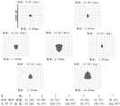
图4为本发明光学镜组的调制传递函数图,即MTF(Modulation TransferFunction)图,MTF图用于是指调制度与图像内每毫米线对数之间的关系,用于评价对景物细部还原能力;其中最上面黑色实线是理论上没有像差的曲线,越靠近黑色实线成像质量越好。Fig. 4 is the modulation transfer function diagram of the optical lens group of the present invention, that is, the MTF (Modulation Transfer Function) diagram. The MTF diagram is used to refer to the relationship between the degree of modulation and the logarithm of lines per millimeter in the image, and is used to evaluate the ability to restore the details of the scene ; Among them, the uppermost black solid line is a curve with no aberration in theory, and the closer to the black solid line, the better the imaging quality.
图5为本发明光学镜组的点列图;其中点列图是指由一点发出的许多光线经光学组件后,因像差使其与像面的交点不再集中于同一点,而形成了一个散布在一定范围的弥散图形,用于评价所述投影光学系统的成像质量。均方根半径值和几何半径值越小成像质量越好。区域1~7的排列顺序是由左至右,由上至下。Fig. 5 is the spot diagram of the optical lens group of the present invention; Wherein the spot diagram refers to that after many rays of light emitted by one point pass through the optical assembly, the intersections with the image plane are no longer concentrated on the same point due to aberration, forming a Diffusion patterns scattered in a certain range are used to evaluate the imaging quality of the projection optical system. The smaller the root mean square radius value and geometric radius value, the better the imaging quality.
图6为本发明光学镜组的场曲与畸变图,其中,场曲是指像场弯曲,主要用于表示光学组件中,整个光束的交点与理想像点的不重合程度。畸变是指物体通过光学组件成像时,物体不同部分有不同的放大率的像差,畸变会导致物像的相似性变坏,但不影响像的清晰度。Fig. 6 is a diagram of field curvature and distortion of the optical mirror assembly of the present invention, wherein the field curvature refers to the curvature of the image field, and is mainly used to indicate the degree of misalignment between the intersection point of the entire light beam and the ideal image point in the optical component. Distortion refers to the aberration of different parts of the object with different magnifications when the object is imaged by the optical component. The distortion will cause the similarity of the object image to deteriorate, but it will not affect the clarity of the image.
图7为本发明光学镜组的色差图,其中,垂轴色差是指又称为倍率色差,主要是指物方的一根复色主光线,因折射系统存在色散,在像方出射时变成多根光线。Fig. 7 is the chromatic aberration diagram of the optical lens group of the present invention, wherein, the vertical axis chromatic aberration is also called the magnification chromatic aberration, mainly refers to a polychromatic chief ray of the object side, because there is dispersion in the refraction system, it becomes Multiple rays.
图8为本发明光学镜组的相对照度图,在一个视角方向上测量得出的照度值,反映光学组件成像的亮度情况,一般中心亮度高,周边亮度低。Fig. 8 is a relative illuminance diagram of the optical mirror assembly of the present invention. The illuminance value measured in a viewing angle direction reflects the brightness of the imaging of the optical component. Generally, the center brightness is high and the peripheral brightness is low.
本发明还提供一种头戴显示设备,包括:透明保护层70和如上文所述光学组件,所述透明保护层70设置于所述光源10的出光面。具体的,透明保护层70盖设在光源10的出光面,在避免影响光束出射的情况下,能够对光源10进行保护,例如采用玻璃保护板,玻璃保护板的厚度大于0.3mm。The present invention also provides a head-mounted display device, comprising: a transparent
本发明还提供一种光学系统,光学系统包括显示器60和如上文的光学镜组,显示器60发射光线610,光学镜组接收显示器发射的光线610,光学系统的总长度小于6mm。在显示器60的出光面设置透明保护板70,保护显示器60的出光面。透镜本体10的折射率为n,色散系数为v,厚度为T,则满足1.45<n<1.60,50<v<75,2mm<T<6mm。其中,厚度T的范围是指透镜本体10的最薄处至最厚处范围。The present invention also provides an optical system, the optical system includes a
其中,光学系统的具体实施方式,可以参照光学镜组的实施例,在此不在赘述。Wherein, for the specific implementation manner of the optical system, reference may be made to the embodiment of the optical lens group, and details are not repeated here.
进一步地,光学系统还包括四分之一波片,四分之一波片设于显示器60的出光面。显示器60发射的光线为圆偏振光,经过四分之一波片后,保证光线的偏振状态转换为线偏振光,第一偏振态和第二偏振态的光线就可以是线偏振光,第一偏振态的光线和第二偏振态的光线偏振方向不同。Further, the optical system further includes a quarter-wave plate, and the quarter-wave plate is disposed on the light-emitting surface of the
本发明还提供一种头戴显示设备,头戴显示设备包括外壳和如上文光学镜组,光学镜组设于外壳。光学镜组可以设于外壳内,也可以采用半包的方式包裹光学镜组。通过外壳保护,还能够起到防灰防水的作用。The present invention also provides a head-mounted display device. The head-mounted display device includes a casing and an optical lens group as above, and the optical lens group is arranged on the casing. The optical lens group can be arranged in the casing, or can be wrapped in a half-wrapped manner. Through the protection of the shell, it can also play the role of dustproof and waterproof.
其中,头戴显示设备的具体实施方式,可以参照光学镜组的实施例,在此不在赘述。Wherein, for the specific implementation manner of the head-mounted display device, reference may be made to the embodiment of the optical lens group, which will not be repeated here.
以上仅为本发明的优选实施例,并非因此限制本发明的专利范围,凡是在本发明的发明构思下,利用本发明说明书及附图内容所作的等效结构变换,或直接/间接运用在其他相关的技术领域均包括在本发明的专利保护范围内。The above are only preferred embodiments of the present invention, and are not intended to limit the patent scope of the present invention. Under the inventive concept of the present invention, the equivalent structural transformation made by using the description of the present invention and the contents of the accompanying drawings, or directly/indirectly used in other All relevant technical fields are included in the patent protection scope of the present invention.
Claims (10)
Priority Applications (3)
| Application Number | Priority Date | Filing Date | Title |
|---|---|---|---|
| CN202110489112.8ACN113219665B (en) | 2021-04-30 | 2021-04-30 | Optical lens group, optical system and head-mounted display device |
| US18/288,878US20240210716A1 (en) | 2021-04-30 | 2021-11-26 | Optical lens assembly, optical system and head-mounted display device |
| PCT/CN2021/133311WO2022227540A1 (en) | 2021-04-30 | 2021-11-26 | Optical lens set, optical system and head-mounted display apparatus |
Applications Claiming Priority (1)
| Application Number | Priority Date | Filing Date | Title |
|---|---|---|---|
| CN202110489112.8ACN113219665B (en) | 2021-04-30 | 2021-04-30 | Optical lens group, optical system and head-mounted display device |
Publications (2)
| Publication Number | Publication Date |
|---|---|
| CN113219665A CN113219665A (en) | 2021-08-06 |
| CN113219665Btrue CN113219665B (en) | 2022-11-22 |
Family
ID=77090924
Family Applications (1)
| Application Number | Title | Priority Date | Filing Date |
|---|---|---|---|
| CN202110489112.8AActiveCN113219665B (en) | 2021-04-30 | 2021-04-30 | Optical lens group, optical system and head-mounted display device |
Country Status (3)
| Country | Link |
|---|---|
| US (1) | US20240210716A1 (en) |
| CN (1) | CN113219665B (en) |
| WO (1) | WO2022227540A1 (en) |
Families Citing this family (8)
| Publication number | Priority date | Publication date | Assignee | Title |
|---|---|---|---|---|
| CN113219665B (en)* | 2021-04-30 | 2022-11-22 | 歌尔股份有限公司 | Optical lens group, optical system and head-mounted display device |
| CN113934007A (en)* | 2021-10-27 | 2022-01-14 | 歌尔光学科技有限公司 | Optical module and head-mounted display device |
| CN114488538B (en)* | 2022-02-28 | 2024-02-09 | 歌尔光学科技有限公司 | AR ray apparatus and wear display device |
| CN114779520A (en)* | 2022-05-25 | 2022-07-22 | 深圳蓝鲸世纪科技有限公司 | Optical system and display apparatus |
| WO2023225963A1 (en)* | 2022-05-26 | 2023-11-30 | 华为技术有限公司 | Scanning device, laser radar, and terminal |
| CN116300118A (en)* | 2023-02-13 | 2023-06-23 | 业桓科技(成都)有限公司 | Optical modules and electronic equipment |
| CN117492211A (en)* | 2023-04-28 | 2024-02-02 | 武汉华星光电技术有限公司 | Display apparatus |
| CN116907351B (en)* | 2023-09-14 | 2023-11-24 | 深圳市深视智能科技有限公司 | Measuring sensor and measuring device |
Family Cites Families (19)
| Publication number | Priority date | Publication date | Assignee | Title |
|---|---|---|---|---|
| JP2005091445A (en)* | 2003-09-12 | 2005-04-07 | Sharp Corp | Image display device |
| US20120050859A1 (en)* | 2010-08-25 | 2012-03-01 | Walsin Lihwa Corporation | Polarized light converting system |
| CN109154426A (en)* | 2016-05-20 | 2019-01-04 | 富士胶片株式会社 | Light guide member and back light unit and liquid crystal display device |
| CN106707510A (en)* | 2016-12-14 | 2017-05-24 | 浙江舜通智能科技有限公司 | Contact lens type optical system and head-mounted display equipped with same |
| KR101909374B1 (en)* | 2017-02-23 | 2018-10-17 | 엘지전자 주식회사 | Head up display for vehicle |
| KR102490630B1 (en)* | 2017-12-26 | 2023-01-20 | 엘지디스플레이 주식회사 | Display apparatus having an eyepiece |
| CN108169904A (en)* | 2017-12-28 | 2018-06-15 | 重庆爱奇艺智能科技有限公司 | A component for displaying information |
| CN108803061A (en)* | 2018-05-31 | 2018-11-13 | 成都理想境界科技有限公司 | A kind of optical amplifier module folding light path |
| CN109613703A (en)* | 2018-12-17 | 2019-04-12 | 重庆爱奇艺智能科技有限公司 | A display device based on a folded optical path |
| CN110161699B (en)* | 2019-06-14 | 2020-10-27 | 合肥视涯技术有限公司 | Virtual reality display device |
| CN210534439U (en)* | 2019-08-05 | 2020-05-15 | 青岛小鸟看看科技有限公司 | Display optical device and head-mounted apparatus |
| CN110716314A (en)* | 2019-11-26 | 2020-01-21 | 深圳惠牛科技有限公司 | Light and thin type optical module and VR equipment |
| CN211375190U (en)* | 2020-02-25 | 2020-08-28 | 深圳惠牛科技有限公司 | VR optical module and display device |
| CN111443491A (en)* | 2020-04-30 | 2020-07-24 | 京东方科技集团股份有限公司 | Optical display system, control method and display device |
| CN212623170U (en)* | 2020-05-18 | 2021-02-26 | 成都忆光年文化传播有限公司 | Compact optical module and near-to-eye display device |
| CN212111989U (en)* | 2020-05-27 | 2020-12-08 | 歌尔光学科技有限公司 | Optical system and virtual reality equipment |
| CN212391670U (en)* | 2020-06-29 | 2021-01-22 | 歌尔光学科技有限公司 | Augmented reality device |
| CN212846157U (en)* | 2020-10-22 | 2021-03-30 | 青岛歌尔声学科技有限公司 | Imaging structure and head-mounted display device |
| CN113219665B (en)* | 2021-04-30 | 2022-11-22 | 歌尔股份有限公司 | Optical lens group, optical system and head-mounted display device |
- 2021
- 2021-04-30CNCN202110489112.8Apatent/CN113219665B/enactiveActive
- 2021-11-26USUS18/288,878patent/US20240210716A1/enactivePending
- 2021-11-26WOPCT/CN2021/133311patent/WO2022227540A1/ennot_activeCeased
Also Published As
| Publication number | Publication date |
|---|---|
| US20240210716A1 (en) | 2024-06-27 |
| WO2022227540A1 (en) | 2022-11-03 |
| CN113219665A (en) | 2021-08-06 |
Similar Documents
| Publication | Publication Date | Title |
|---|---|---|
| CN113219665B (en) | Optical lens group, optical system and head-mounted display device | |
| CN109946837B (en) | an optical imaging system | |
| CN114236825B (en) | Optical system and head-mounted display device | |
| CN112596240B (en) | Imaging optical path and head-mounted display device | |
| CN211826725U (en) | Optical system of micro head-mounted display | |
| CN114967135B (en) | Ultra-short throw eyepiece system | |
| CN214751118U (en) | Optical system and head-mounted display apparatus | |
| US20240264445A1 (en) | Optical module and head mount display | |
| CN210776039U (en) | Miniaturized Short-Range Optical System | |
| WO2022227539A1 (en) | Optical module and head-mounted display device | |
| CN209858857U (en) | Optical system and virtual reality equipment with same | |
| TWM615839U (en) | Ultra short distance eyepiece system | |
| TWI797563B (en) | Ultra short distance eyepiece system | |
| CN113391447A (en) | Optical system of miniature head-mounted display | |
| WO2023221239A1 (en) | Optical module and head-mounted display device | |
| TWM596873U (en) | Optical system of miniature head-mounted display | |
| CN118068563B (en) | Optical systems and display devices | |
| WO2022227538A1 (en) | Cemented lens group and head-mounted display device | |
| CN117075337A (en) | Optical module and head-mounted display device | |
| TWM591624U (en) | Short distance optical system | |
| CN111929907A (en) | Image display structure and head-mounted display device | |
| TW202134734A (en) | Optical system of miniature head-mounted display achieving an optical distance with a similar length by virtue of the phase delay and multiple reflection of rays | |
| CN113219667B (en) | Optics and Head Mounted Displays | |
| CN115373149A (en) | head mounted display device | |
| CN215116991U (en) | Augmented reality display system and augmented reality display equipment |
Legal Events
| Date | Code | Title | Description |
|---|---|---|---|
| PB01 | Publication | ||
| PB01 | Publication | ||
| SE01 | Entry into force of request for substantive examination | ||
| SE01 | Entry into force of request for substantive examination | ||
| GR01 | Patent grant | ||
| GR01 | Patent grant | ||
| TR01 | Transfer of patent right | ||
| TR01 | Transfer of patent right | Effective date of registration:20221128 Address after:261031 workshop 1, phase III, Geer Photoelectric Industrial Park, 3999 Huixian Road, Yongchun community, Qingchi street, high tech Zone, Weifang City, Shandong Province Patentee after:GoerTek Optical Technology Co.,Ltd. Address before:261031 No. 268 Dongfang Road, hi tech Industrial Development Zone, Shandong, Weifang Patentee before:GOERTEK Inc. |