CN113203433B - Coal mine underground water inrush early warning monitoring device and method - Google Patents
Coal mine underground water inrush early warning monitoring device and methodDownload PDFInfo
- Publication number
- CN113203433B CN113203433BCN202110351971.0ACN202110351971ACN113203433BCN 113203433 BCN113203433 BCN 113203433BCN 202110351971 ACN202110351971 ACN 202110351971ACN 113203433 BCN113203433 BCN 113203433B
- Authority
- CN
- China
- Prior art keywords
- water
- monitoring
- coal mine
- early warning
- installation
- Prior art date
- Legal status (The legal status is an assumption and is not a legal conclusion. Google has not performed a legal analysis and makes no representation as to the accuracy of the status listed.)
- Active
Links
- XLYOFNOQVPJJNP-UHFFFAOYSA-NwaterSubstancesOXLYOFNOQVPJJNP-UHFFFAOYSA-N0.000titleclaimsabstractdescription547
- 238000012806monitoring deviceMethods0.000titleclaimsabstractdescription75
- 239000003245coalSubstances0.000titleclaimsabstractdescription72
- 238000000034methodMethods0.000titleclaimsabstractdescription28
- 238000009434installationMethods0.000claimsabstractdescription186
- 238000012544monitoring processMethods0.000claimsabstractdescription99
- 230000002093peripheral effectEffects0.000claimsabstractdescription20
- 230000000007visual effectEffects0.000claimsabstract4
- 230000007246mechanismEffects0.000claimsdescription66
- 238000004891communicationMethods0.000claimsdescription5
- 239000000126substanceSubstances0.000claimsdescription3
- 239000012466permeateSubstances0.000claims1
- 230000009286beneficial effectEffects0.000abstractdescription7
- 235000017166Bambusa arundinaceaNutrition0.000abstract2
- 235000017491Bambusa tuldaNutrition0.000abstract2
- 241001330002BambuseaeSpecies0.000abstract2
- 235000015334Phyllostachys viridisNutrition0.000abstract2
- 239000011425bambooSubstances0.000abstract2
- 238000001514detection methodMethods0.000description56
- 239000000523sampleSubstances0.000description49
- 238000005192partitionMethods0.000description29
- 230000001681protective effectEffects0.000description21
- 230000008859changeEffects0.000description17
- 238000011144upstream manufacturingMethods0.000description15
- 238000006243chemical reactionMethods0.000description13
- 230000035939shockEffects0.000description13
- 230000008569processEffects0.000description12
- 230000000694effectsEffects0.000description11
- 238000007689inspectionMethods0.000description10
- 239000003990capacitorSubstances0.000description9
- XEEYBQQBJWHFJM-UHFFFAOYSA-NIronChemical compound[Fe]XEEYBQQBJWHFJM-UHFFFAOYSA-N0.000description8
- 230000006378damageEffects0.000description8
- 238000007789sealingMethods0.000description8
- 230000005484gravityEffects0.000description7
- 239000003673groundwaterSubstances0.000description7
- 238000005065miningMethods0.000description7
- 230000008878couplingEffects0.000description5
- 238000010168coupling processMethods0.000description5
- 238000005859coupling reactionMethods0.000description5
- 230000005611electricityEffects0.000description5
- 210000004907glandAnatomy0.000description5
- 239000012535impuritySubstances0.000description5
- 230000004941influxEffects0.000description5
- 230000007774longtermEffects0.000description5
- 239000002245particleSubstances0.000description5
- 238000012545processingMethods0.000description5
- 239000011435rockSubstances0.000description5
- 238000006424Flood reactionMethods0.000description4
- 230000009471actionEffects0.000description4
- 239000000945fillerSubstances0.000description4
- 238000007667floatingMethods0.000description4
- 229910052742ironInorganic materials0.000description4
- 239000006096absorbing agentSubstances0.000description3
- 238000010586diagramMethods0.000description3
- 238000010521absorption reactionMethods0.000description2
- 230000008901benefitEffects0.000description2
- 230000000903blocking effectEffects0.000description2
- AXCZMVOFGPJBDE-UHFFFAOYSA-Lcalcium dihydroxideChemical compound[OH-].[OH-].[Ca+2]AXCZMVOFGPJBDE-UHFFFAOYSA-L0.000description2
- 238000013461designMethods0.000description2
- 238000011161developmentMethods0.000description2
- 238000005553drillingMethods0.000description2
- 238000004519manufacturing processMethods0.000description2
- 238000012986modificationMethods0.000description2
- 230000004048modificationEffects0.000description2
- 239000013307optical fiberSubstances0.000description2
- 239000002243precursorSubstances0.000description2
- 230000001105regulatory effectEffects0.000description2
- 230000002159abnormal effectEffects0.000description1
- 230000006978adaptationEffects0.000description1
- 238000004458analytical methodMethods0.000description1
- 238000004873anchoringMethods0.000description1
- 238000013528artificial neural networkMethods0.000description1
- 238000009412basement excavationMethods0.000description1
- 230000015572biosynthetic processEffects0.000description1
- 238000010219correlation analysisMethods0.000description1
- 238000013016dampingMethods0.000description1
- 238000005516engineering processMethods0.000description1
- 238000011156evaluationMethods0.000description1
- 239000012530fluidSubstances0.000description1
- 230000003116impacting effectEffects0.000description1
- 230000006872improvementEffects0.000description1
- 238000003780insertionMethods0.000description1
- 230000037431insertionEffects0.000description1
- 238000009413insulationMethods0.000description1
- 229910001234light alloyInorganic materials0.000description1
- 238000012423maintenanceMethods0.000description1
- 239000000463materialSubstances0.000description1
- 238000005259measurementMethods0.000description1
- 239000007769metal materialSubstances0.000description1
- 239000000203mixtureSubstances0.000description1
- 239000013618particulate matterSubstances0.000description1
- 239000004033plasticSubstances0.000description1
- 238000005086pumpingMethods0.000description1
- 230000008439repair processEffects0.000description1
- 230000002441reversible effectEffects0.000description1
- 239000002893slagSubstances0.000description1
- 230000000087stabilizing effectEffects0.000description1
- 239000010935stainless steelSubstances0.000description1
- 229910001220stainless steelInorganic materials0.000description1
- 239000004575stoneSubstances0.000description1
- 238000012360testing methodMethods0.000description1
Images


Classifications
- G—PHYSICS
- G01—MEASURING; TESTING
- G01D—MEASURING NOT SPECIALLY ADAPTED FOR A SPECIFIC VARIABLE; ARRANGEMENTS FOR MEASURING TWO OR MORE VARIABLES NOT COVERED IN A SINGLE OTHER SUBCLASS; TARIFF METERING APPARATUS; MEASURING OR TESTING NOT OTHERWISE PROVIDED FOR
- G01D21/00—Measuring or testing not otherwise provided for
- G01D21/02—Measuring two or more variables by means not covered by a single other subclass
- G—PHYSICS
- G08—SIGNALLING
- G08B—SIGNALLING OR CALLING SYSTEMS; ORDER TELEGRAPHS; ALARM SYSTEMS
- G08B21/00—Alarms responsive to a single specified undesired or abnormal condition and not otherwise provided for
- G08B21/02—Alarms for ensuring the safety of persons
- G08B21/10—Alarms for ensuring the safety of persons responsive to calamitous events, e.g. tornados or earthquakes
Landscapes
- Physics & Mathematics (AREA)
- General Physics & Mathematics (AREA)
- Life Sciences & Earth Sciences (AREA)
- Environmental & Geological Engineering (AREA)
- General Life Sciences & Earth Sciences (AREA)
- Geology (AREA)
- Business, Economics & Management (AREA)
- Emergency Management (AREA)
- Emergency Alarm Devices (AREA)
Abstract
Description
Translated fromChinese技术领域technical field
本发明涉及煤矿突水预警技术领域,尤其涉及一种煤矿井下突水预警监测装置及方法。The invention relates to the technical field of coal mine water inrush early warning, in particular to a coal mine underground water inrush early warning monitoring device and method.
背景技术Background technique
矿井突水是掘进或采矿过程中当巷道揭穿导水断裂、富水溶洞、积水老窿,大量地下水突然涌入矿山井巷的现象。当巷道底板下有间接充水层时,便会在地下水压力和矿山压力作用下,破坏底板隔水层,形成人工裂隙通道,导致下部高压地下水涌入井巷造成突水。矿井突水一般来势凶猛,常会在短时间内淹没坑道,给矿山生产带来危害,造成人员伤亡。在富水的岩溶水充水的矿区及顶底板有较厚高压含水层分布的矿山区,在构造破碎的地段,常易发生矿井突水。Mine water inrush is a phenomenon in which a large amount of groundwater suddenly pours into the mine shaft when the roadway exposes the water-conducting fracture, the water-rich karst cave, and the water-filled hole during the excavation or mining process. When there is an indirect water-filled layer under the roadway floor, under the action of groundwater pressure and mine pressure, the floor aquifer will be destroyed, forming artificial crack channels, resulting in the influx of high-pressure groundwater from the lower part of the well and roadway. Mine water inrush is generally ferocious, often flooding tunnels in a short period of time, causing harm to mine production and causing casualties. In the mining area filled with water-rich karst water and the mining area with thick high-pressure aquifers distributed on the roof and floor, mine water inrush is often prone to occur in the section with broken structure.
水灾对矿井造成的破坏是毁灭性的,由于水灾发生的预测性难的原因,一旦水灾发生,不仅会造成矿井人员的严重伤亡,造成难以估算的损失,同时还会对矿井造成难以修复的结局,造成的经济损失更是不言而喻。更有一个明显的问题就是水灾造成的矿井灾害抢救难度大,一旦产生水灾,基本上很难在有限的时间内挽回人员的生命和经济损失。所以说水害是影响矿井安全的非常重要的问题之一。The damage caused by floods to mines is devastating. Due to the difficulty in predicting the occurrence of floods, once a flood occurs, it will not only cause serious casualties of mine personnel and cause incalculable losses, but also cause difficult repairs to the mine. , the economic loss is self-evident. Another obvious problem is that it is very difficult to rescue mine disasters caused by floods. Once floods occur, it is basically difficult to save lives and economic losses within a limited time. Therefore, water damage is one of the very important issues affecting mine safety.
现有煤矿突水监测方法往往采用水质、水量、温度、湿度、气体成分、裂隙等单一监测指标对矿井突水进行监测,监测结果准确性差。对于现有通过监测水质来进行煤矿井下突水预警监测的监测装置,因为水流中掺杂有碎石等杂物,容易撞击到水质传感器,造成水质传感器的损坏,不利于进行长期稳定的水质监测,对于简单设置滤网进行遮挡的方式,滤网容易堵塞,使监测装置丧失监测功能。现有煤矿突水监测方法只能监测是否发生突水或者在突水前进行预判,却忽视了对于已经发生突水的矿井的水仓内的水位监测,因此无法对水仓内的设备进行及时安全有效地抢救。The existing coal mine water inrush monitoring methods often use single monitoring indicators such as water quality, water quantity, temperature, humidity, gas composition, and fissures to monitor mine water inrush, and the monitoring results are inaccurate. For the existing monitoring devices that monitor water quality in coal mines for early warning and monitoring of underground water inrush, because the water flow is mixed with debris such as gravel, it is easy to hit the water quality sensor, causing damage to the water quality sensor, which is not conducive to long-term and stable water quality monitoring. , For the way of simply setting the filter screen to block, the filter screen is easy to block, so that the monitoring device loses the monitoring function. The existing coal mine water inrush monitoring methods can only monitor whether water inrush occurs or make predictions before water inrush, but ignore the water level monitoring in the water tank of mines where water inrush has occurred, so it is impossible to monitor the equipment in the water tank. Timely, safe and effective rescue.
发明内容SUMMARY OF THE INVENTION
(一)发明目的(1) Purpose of the invention
为解决背景技术中存在的技术问题,本发明提出一种煤矿井下突水预警监测装置及方法,能在保证水质传感器正常监测的前提下,对水质传感器进行安全防护,且能避免堵塞情况发生,有利于长时间稳定的进行水质监测,从而能长时间进行煤矿井下突水预警监测。In order to solve the technical problems existing in the background technology, the present invention proposes a coal mine underground water inrush early warning monitoring device and method, which can protect the water quality sensor safely and avoid the occurrence of blockage on the premise of ensuring the normal monitoring of the water quality sensor. It is conducive to long-term and stable water quality monitoring, so as to carry out early warning monitoring of underground water inrush in coal mines for a long time.
(二)技术方案(2) Technical solutions
本发明第一方面:The first aspect of the present invention:
提供一种煤矿井下突水预警监测装置,包括水质监测机构、中央控制器、声光报警器;水质监测机构包括导流罩、安装筒、转动柱、第一螺旋叶片、水质传感器和安装罩;导流罩设置有多个进水孔,且转动安装于安装筒的进水端;第一螺旋叶片设置在转动柱上,转动柱和第一螺旋叶片同轴设置在安装筒内,第一螺旋叶片和安装筒内壁之间设置有流水通道;安装罩通过安装台组件固定在安装筒的外周面上,安装台组件包括第一安装台和第二安装台,第一安装台上设置有用于驱动导流罩和转动柱转动的驱动机构,水质传感器通过第二安装台插入安装筒内部,声光报警器设置在安装罩顶部,水质传感器与中央控制器通讯连接,中央控制器与驱动机构和声光报警器分别控制连接。Provided is an early warning and monitoring device for water inrush in a coal mine, comprising a water quality monitoring mechanism, a central controller, and an acousto-optic alarm; the water quality monitoring mechanism includes a diversion cover, an installation cylinder, a rotating column, a first spiral blade, a water quality sensor and an installation cover; The diversion hood is provided with a plurality of water inlet holes, and is rotatably installed on the water inlet end of the installation cylinder; the first helical blade is arranged on the rotating column, the rotating column and the first helical blade are coaxially arranged in the installation cylinder, and the first helical blade is arranged in the installation cylinder. A water flow channel is arranged between the blade and the inner wall of the installation cylinder; the installation cover is fixed on the outer peripheral surface of the installation cylinder through the installation table assembly, the installation table assembly includes a first installation table and a second installation table, and the first installation table is provided with a drive for driving The shroud and the driving mechanism for the rotation of the rotating column, the water quality sensor is inserted into the installation cylinder through the second installation platform, the sound and light alarm is arranged on the top of the installation cover, the water quality sensor is connected to the central controller, and the central controller and the driving mechanism are in harmony. The light alarms control the connections separately.
本发明一种优选实施方式,安装筒内设有过滤组件,过滤组件包括第一滤板和第二滤板,第一滤板和第二滤板沿水流方向依次同轴设置于安装筒的两端。In a preferred embodiment of the present invention, a filter assembly is arranged in the installation cylinder, and the filter assembly includes a first filter plate and a second filter plate, and the first filter plate and the second filter plate are coaxially arranged on two sides of the installation cylinder in turn along the water flow direction. end.
本发明一种优选实施方式,导流罩为半球形结构,导流罩外周面上设置有导流槽,导流槽呈弧线形设置,多个进水孔均匀设置在导流槽的槽底。In a preferred embodiment of the present invention, the shroud is a hemispherical structure, the outer peripheral surface of the shroud is provided with a diversion groove, the diversion groove is arranged in an arc shape, and a plurality of water inlet holes are evenly arranged in the groove of the diversion groove end.
本发明一种优选实施方式,进水孔沿轴向逐渐向水流方向倾斜,进水孔孔径沿水流方向逐渐增大。In a preferred embodiment of the present invention, the water inlet hole is gradually inclined to the water flow direction along the axial direction, and the diameter of the water inlet hole gradually increases along the water flow direction.
本发明一种优选实施方式,进水孔边缘处设置有圆角。In a preferred embodiment of the present invention, rounded corners are provided at the edge of the water inlet hole.
本发明一种优选实施方式,第一滤板和第二滤板上均设置有滤孔,且滤孔孔径沿水流方向逐渐增大。In a preferred embodiment of the present invention, both the first filter plate and the second filter plate are provided with filter holes, and the diameter of the filter holes gradually increases along the water flow direction.
本发明一种优选实施方式,驱动机构包括电机、第一转动轴、第一锥齿轮、第二锥齿轮、第三锥齿轮、第二转动轴、第三转动轴、球形罩和固定杆,电机设置在第一安装台上,电机与第一转动轴驱动连接,第一转动轴竖直设置,第一转动轴转动设置在第一安装台上,第一转动轴底端与第一锥齿轮连接,第一锥齿轮、第二锥齿轮和第三锥齿轮均位于球形罩内侧,第一锥齿轮与第二锥齿轮和第三锥齿轮同时啮合连接,第二锥齿轮和第三锥齿轮沿安装筒轴向并排设置,第二转动轴和第三转动轴均与安装筒同轴设置,第二转动轴和第三转动轴均转动设置在球形罩上,第二转动轴贯穿第一滤板,第二转动轴两端分别与导流罩和第二锥齿轮连接,第三转动轴两端分别与第三锥齿轮和转动柱连接,球形罩设置在固定杆上,固定杆设置在安装筒内壁上。In a preferred embodiment of the present invention, the driving mechanism includes a motor, a first rotating shaft, a first bevel gear, a second bevel gear, a third bevel gear, a second rotating shaft, a third rotating shaft, a spherical cover and a fixed rod. It is arranged on the first mounting table, the motor is drivingly connected with the first rotating shaft, the first rotating shaft is vertically arranged, the first rotating shaft is rotatably arranged on the first mounting table, and the bottom end of the first rotating shaft is connected with the first bevel gear , the first bevel gear, the second bevel gear and the third bevel gear are all located inside the spherical cover, the first bevel gear is meshed with the second bevel gear and the third bevel gear at the same time, and the second bevel gear and the third bevel gear are installed along the The cylinders are axially arranged side by side, the second rotating shaft and the third rotating shaft are coaxial with the installation cylinder, both the second rotating shaft and the third rotating shaft are rotatably arranged on the spherical cover, and the second rotating shaft penetrates the first filter plate, Both ends of the second rotating shaft are respectively connected with the shroud and the second bevel gear, and both ends of the third rotating shaft are respectively connected with the third bevel gear and the rotating column. superior.
本发明一种优选实施方式,安装筒内壁上设置有第二螺旋叶片,第一螺旋叶片和第二螺旋叶片沿安装筒径向之间设置有间隔通道。In a preferred embodiment of the present invention, the inner wall of the installation cylinder is provided with a second helical blade, and an interval channel is provided between the first helical blade and the second helical blade along the radial direction of the installation cylinder.
本发明一种优选实施方式,水质传感器沿水流方向并排设置有两个,水质传感器底端靠近第二螺旋叶片前侧表面设置。In a preferred embodiment of the present invention, two water quality sensors are arranged side by side along the water flow direction, and the bottom end of the water quality sensor is arranged close to the front surface of the second helical blade.
本发明一种优选实施方式,煤矿井下突水预警监测装置还包括固定架,安装罩固定在固定架上,固定架为U形结构,且U形开口朝下设置,固定架两端底部均设置有固定钉。In a preferred embodiment of the present invention, the coal mine underground water inrush early warning monitoring device further includes a fixing frame, the installation cover is fixed on the fixing frame, the fixing frame is a U-shaped structure, and the U-shaped opening is arranged downward, and the bottoms of both ends of the fixing frame are arranged at the bottom Has fixing pegs.
本发明一种优选实施方式,煤矿井下突水预警监测装置还包括震动监测机构,震动监测机构固定于固定架上与煤矿巷道内壁接触,用于监测煤矿巷道的振动。In a preferred embodiment of the present invention, the coal mine underground water inrush early warning monitoring device further includes a vibration monitoring mechanism, which is fixed on the fixed frame and contacts the inner wall of the coal mine roadway for monitoring the vibration of the coal mine roadway.
本发明一种优选实施方式,震动监测机构包括固定板、震动传感器、安装板、固定台、螺杆、旋钮和导向杆,固定板设置在固定架上,震动传感器设置在安装板上,震动传感器与中央控制器通讯连接,固定台与安装板连接,螺杆一端与固定台转动连接,螺杆另一端与旋钮连接,螺杆贯穿固定板并与固定板螺纹连接,导向杆与螺杆并排设置,导向杆端部与安装板连接,导向杆滑动设置在固定板上。In a preferred embodiment of the present invention, the vibration monitoring mechanism includes a fixed plate, a vibration sensor, a mounting plate, a fixed table, a screw rod, a knob and a guide rod, the fixed plate is arranged on the fixing frame, the vibration sensor is arranged on the installation plate, and the vibration sensor is connected to the mounting plate. The central controller is connected by communication, the fixing table is connected with the mounting plate, one end of the screw rod is connected with the fixing table in rotation, the other end of the screw rod is connected with the knob, the screw rod penetrates the fixing plate and is threadedly connected with the fixing plate, the guide rod and the screw rod are arranged side by side, and the end of the guide rod is Connected with the mounting plate, the guide rod is slidably arranged on the fixing plate.
本发明一种优选实施方式,导向杆远离安装板的一端连接有连接板,螺杆贯穿连接板。In a preferred embodiment of the present invention, one end of the guide rod away from the mounting plate is connected with a connecting plate, and the screw rod penetrates through the connecting plate.
本发明一种优选实施方式,第一安装台和第二安装台均为柱状结构,第一安装台设置第一中心孔,第一转轴穿过第一中心孔与电机输出轴连接;第二安装台设置第二中心孔,水质传感器安装于第二中心孔内,水质传感器的前端伸入至安装筒的内部。In a preferred embodiment of the present invention, the first installation platform and the second installation platform are both columnar structures, the first installation platform is provided with a first central hole, and the first rotating shaft passes through the first central hole to connect with the motor output shaft; The platform is provided with a second center hole, the water quality sensor is installed in the second center hole, and the front end of the water quality sensor extends into the interior of the installation cylinder.
本发明一种优选实施方式,安装罩为密封的箱体结构,包括顶壁、底壁和侧壁,顶壁、底壁和侧壁一体成型或密封拼接而成。In a preferred embodiment of the present invention, the installation cover is a sealed box structure, including a top wall, a bottom wall and a side wall, and the top wall, bottom wall and side wall are integrally formed or sealed and spliced together.
本发明一种优选实施方式,安装罩的底壁设有第一安装口和第二安装口,第一安装台和第二安装台的第一端与安装筒外周面固定连接,第一安装台和第二安装台的第二端均位于安装罩的内部空间,第一安装台通过密封圈密封安装于第一安装口,第二安装台通过密封圈密封安装于第二安装口;安装筒外周面设置第一通孔和第二通孔,第一通孔与第一中心孔对应,允许第一转轴穿过,第一转轴与第一中心孔密封转动连接;第二通孔与第二中心孔对应,水质传感器装入第二通孔和第二中心孔,水质传感器的前端穿过安装筒的第二通孔伸入到安装筒内。In a preferred embodiment of the present invention, the bottom wall of the installation cover is provided with a first installation opening and a second installation opening, the first ends of the first installation platform and the second installation platform are fixedly connected to the outer peripheral surface of the installation cylinder, and the first installation platform and the second end of the second installation platform are located in the inner space of the installation cover, the first installation platform is sealed and installed at the first installation port through a sealing ring, and the second installation platform is sealed and installed at the second installation port through a sealing ring; the outer circumference of the installation cylinder The surface is provided with a first through hole and a second through hole, the first through hole corresponds to the first central hole, allows the first shaft to pass through, and the first shaft is sealed and rotatably connected with the first central hole; The holes correspond, the water quality sensor is installed in the second through hole and the second central hole, and the front end of the water quality sensor protrudes into the installation barrel through the second through hole of the installation barrel.
本发明一种优选实施方式,第二安装台的第二中心孔的孔径大于水质传感器的外径,水质传感器通过减震件安装于第二中心孔内。In a preferred embodiment of the present invention, the diameter of the second central hole of the second installation platform is larger than the outer diameter of the water quality sensor, and the water quality sensor is installed in the second central hole through a shock absorbing member.
本发明一种优选实施方式,减震件为弹性充填物,弹性充填物充填于水质传感器与第二中心孔的环形空间内。In a preferred embodiment of the present invention, the shock absorbing member is an elastic filler, and the elastic filler is filled in the annular space between the water quality sensor and the second central hole.
本发明一种优选实施方式,减震件为弹簧,水质传感器通过多个弹簧固定在第二中心孔内;弹簧的第一端固定在第二中心孔的孔壁,弹簧的第二端抵靠在水质传感器的外周壁,或者,水质传感器的下部套设连接环,弹簧的第二端与连接环连接。In a preferred embodiment of the present invention, the damping member is a spring, the water quality sensor is fixed in the second central hole through a plurality of springs; the first end of the spring is fixed on the hole wall of the second central hole, and the second end of the spring abuts against A connecting ring is sleeved on the outer peripheral wall of the water quality sensor, or the lower part of the water quality sensor, and the second end of the spring is connected with the connecting ring.
本发明一种优选实施方式,第二安装台的第二中心孔的孔径由上向下逐渐变大,第二中心孔的纵向截面呈喇叭状或八字形;水质传感器的上部与第二中心孔的上部通过球铰转动连接,第二中心孔的下部空间构成水质传感器的摆动空间。In a preferred embodiment of the present invention, the aperture of the second central hole of the second installation platform gradually increases from top to bottom, and the longitudinal cross-section of the second central hole is trumpet-shaped or figure-eight; the upper part of the water quality sensor and the second central hole are The upper part of the second central hole is rotatably connected by a ball hinge, and the lower space of the second central hole constitutes the swing space of the water quality sensor.
本发明一种优选实施方式,摆动空间内设置减震件。In a preferred embodiment of the present invention, a shock absorbing member is arranged in the swing space.
本发明一种优选实施方式,煤矿井下突水预警监测装置还设置有防倒灌装置,防倒灌装置拆卸设置在安装筒内且位于第二滤板的下游。In a preferred embodiment of the present invention, the coal mine underground water inrush early warning and monitoring device is further provided with an anti-backflow device, and the anti-backflow device is disassembled and arranged in the installation cylinder and is located downstream of the second filter plate.
本发明一种优选实施方式,防倒灌装置包括隔板,隔板的顶端与安装筒的内壁转动连接,隔板的形状与安装筒的内壁形状相适配,隔板能够在上游矿井水的冲击下打开,在自身重力或倒灌矿井水的冲击下关闭。In a preferred embodiment of the present invention, the anti-backflow device includes a baffle, the top of the baffle is rotatably connected to the inner wall of the installation cylinder, the shape of the baffle is adapted to the shape of the inner wall of the installation cylinder, and the baffle can withstand the impact of upstream mine water. It is opened under its own gravity or under the impact of pouring mine water.
本发明一种优选实施方式,隔板的顶端向上游方向倾斜设置;隔板的纵向剖面为对称图形,具有纵向对称轴线,隔板的有效纵向阻挡长度L大于安装筒的内壁直径D,隔板安装在安装筒内后,自然状态下,隔板的顶端与底端之间的距离为L,隔板的重心位于隔板的纵向对称轴线上且距隔板顶端下方的1/5-1/4L处;隔板的纵向对称轴线与竖直方向呈5-8°夹角。In a preferred embodiment of the present invention, the top of the baffle is inclined to the upstream direction; the longitudinal section of the baffle is a symmetrical figure with a longitudinal axis of symmetry, the effective longitudinal blocking length L of the baffle is greater than the diameter D of the inner wall of the installation cylinder, and the baffle is After being installed in the installation cylinder, in the natural state, the distance between the top and bottom ends of the partition is L, and the center of gravity of the partition is located on the longitudinal symmetry axis of the partition and is 1/5-1/5 of the distance below the top of the partition. 4L; the longitudinal axis of symmetry of the partition is at an angle of 5-8° with the vertical direction.
本发明一种优选实施方式,安装筒的内壁设置限位部,限位部用于限制隔板只能向限位部的下游方向摆动,隔板的外沿周边能够与限位部密封贴合。In a preferred embodiment of the present invention, the inner wall of the installation cylinder is provided with a limit portion, the limit portion is used to limit the baffle to swing only in the downstream direction of the limit portion, and the outer periphery of the baffle can be sealed and fit with the limit portion .
本发明一种优选实施方式,隔板的迎水面为凸形曲面,隔板的背水面为凹形曲面。In a preferred embodiment of the present invention, the water-facing surface of the partition plate is a convex curved surface, and the backwater surface of the partition plate is a concave-shaped curved surface.
本发明一种优选实施方式,防倒灌装置设置在距离安装筒的出水口上游30-50cm处。In a preferred embodiment of the present invention, the anti-backflow device is arranged at a distance of 30-50 cm upstream from the water outlet of the installation cylinder.
本发明第二方面:Second aspect of the present invention:
提供一种煤矿井下突水预警监测方法,利用上述的煤矿井下突水预警监测装置,监测方法包括如下步骤:Provided is a method for early warning and monitoring of water inrush in a coal mine, using the above-mentioned device for early warning and monitoring of water inrush in a coal mine, and the monitoring method includes the following steps:
将装置放到煤矿巷道的排水沟中,利用固定架固定本装置,导流罩朝前设置;启动驱动机构和水质传感器,驱动机构驱动导流罩和转动柱转动;Put the device into the drainage ditch of the coal mine roadway, use the fixing frame to fix the device, and set the shroud to the front; start the driving mechanism and the water quality sensor, and the driving mechanism drives the shroud and the rotating column to rotate;
水通过导流槽和进水孔进入导流罩内侧,并依次通过第一滤板、安装筒和第二滤板;The water enters the inside of the guide hood through the guide groove and the water inlet hole, and passes through the first filter plate, the installation cylinder and the second filter plate in sequence;
水质传感器对进入安装筒内的水进行监测,当水质传感器监测到水中掺杂有因井下突水而渗入到排水沟中的物质时,水质传感器向中央控制器发送信号,中央控制器控制声光报警器进行声光报警。The water quality sensor monitors the water entering the installation cylinder. When the water quality sensor detects that the water is mixed with substances that have penetrated into the drainage ditch due to underground water inrush, the water quality sensor sends a signal to the central controller, which controls the sound and light. The alarm will sound and light alarm.
本发明第三方面:The third aspect of the present invention:
提供一种煤矿井下突水预警监测系统,包括上述任一技术方案的煤矿井下突水预警监测装置,还包括矿井突水灾害预警的组合传感器监测装置和/或水仓水位监测装置。Provided is a coal mine underground water inrush early warning and monitoring system, including the coal mine underground water inrush early warning and monitoring device of any of the above technical solutions, and a combined sensor monitoring device and/or a water tank water level monitoring device for mine water inrush disaster early warning.
本发明一种优选实施方式,矿井突水灾害预警的组合传感器监测装置包括机架、伸缩机构、旋转机构和探杆,伸缩机构、旋转机构固定设于机架上,伸缩机构与旋转机构连接,旋转机构与探杆连接,伸缩机构用于驱动旋转机构沿伸缩方向移动,旋转机构用于驱动探杆旋转并固定在指定旋转角度位置;探杆的外周上安装有组合传感器。In a preferred embodiment of the present invention, the combined sensor monitoring device for mine water inrush disaster early warning includes a frame, a telescopic mechanism, a rotating mechanism and a probe rod. The telescopic mechanism and the rotating mechanism are fixed on the frame, and the telescopic mechanism is connected to the rotating mechanism. The rotating mechanism is connected with the probe rod, the telescopic mechanism is used to drive the rotary mechanism to move along the telescopic direction, and the rotating mechanism is used to drive the probe rod to rotate and fix it at a specified rotation angle position; a combination sensor is installed on the outer circumference of the probe rod.
本发明一种优选实施方式,组合传感器包括湿度传感器、水位传感器、温度传感器和水质传感器中的至少两个。In a preferred embodiment of the present invention, the combined sensor includes at least two of a humidity sensor, a water level sensor, a temperature sensor and a water quality sensor.
本发明一种优选实施方式,探杆的前端安装有摄影机,摄影机用于对检测孔的孔壁进行拍摄,并获取检测孔孔壁的裂隙图像及裂隙参数。In a preferred embodiment of the present invention, a camera is installed at the front end of the probe rod, and the camera is used to photograph the hole wall of the detection hole, and obtain the crack image and crack parameters of the hole wall of the detection hole.
本发明一种优选实施方式,伸缩机构包括第一支柱、顶座、伸缩电缸、升降板、基板,中心轴、第二支柱、直线轴承和导柱;其中,顶座通过第一支柱安装在机架的上方,伸缩电缸固定安装在顶座上,导柱顶端固定安装在顶座上,直线轴承安装在导柱上,升降板固定安装在直线轴承上且伸缩电缸伸缩杆末端通过浮动接头安装在升降板上,基板通过第二支柱安装在升降板下方。In a preferred embodiment of the present invention, the telescopic mechanism includes a first column, a top seat, a telescopic electric cylinder, a lifting plate, a base plate, a central shaft, a second column, a linear bearing and a guide column; wherein the top seat is installed on the first column through the first column. Above the frame, the telescopic electric cylinder is fixedly installed on the top seat, the top of the guide column is fixedly installed on the top seat, the linear bearing is installed on the guide column, the lifting plate is fixedly installed on the linear bearing, and the end of the telescopic electric cylinder telescopic rod floats through the The joint is mounted on the lift plate, and the base plate is mounted under the lift plate through the second pillar.
本发明一种优选实施方式,旋转机构包括连接筒、螺母、旋转筒、伺服驱动器、转臂、滚珠导向轴、免键轴衬、联轴器、轴承、浮动接头和轴承压盖;其中,中心轴的顶端通过轴承安装在基板安装孔里,轴承压盖通过螺钉固定安装在基板底面上且轴承压盖压在轴承上,中心轴下端通过联轴器与滚珠导向轴上端连接,伺服驱动器固定安装在机架上的中心孔里,旋转筒顶端通过螺钉安装在伺服驱动器上,螺母安装在滚珠导向轴上且螺母固定安装在旋转筒底部,连接筒通过免键轴衬固定安装在滚珠导向轴下端,转臂的一端固定安装在连接筒的底面上,探杆固定安装在转臂另一端的安装孔里。In a preferred embodiment of the present invention, the rotating mechanism includes a connecting cylinder, a nut, a rotating cylinder, a servo driver, a rotating arm, a ball guide shaft, a keyless bushing, a coupling, a bearing, a floating joint and a bearing gland; wherein, the center The top of the shaft is installed in the mounting hole of the base plate through the bearing, the bearing gland is fixedly installed on the bottom surface of the base plate by screws and the bearing gland is pressed on the bearing, the lower end of the central shaft is connected with the upper end of the ball guide shaft through the coupling, and the servo driver is fixedly installed In the center hole on the frame, the top of the rotating cylinder is installed on the servo driver by screws, the nut is installed on the ball guide shaft and the nut is fixed at the bottom of the rotating cylinder, and the connecting cylinder is fixedly installed on the lower end of the ball guide shaft through a keyless bushing , one end of the rotating arm is fixedly installed on the bottom surface of the connecting cylinder, and the probe rod is fixedly installed in the installation hole at the other end of the rotating arm.
本发明一种优选实施方式,水仓水位监测装置包括安装框架、第一合页、多色指示灯、电源继电器转换箱、磁吸搭扣、高音报警模块、水位探测模块、一级水位探头、二级水位探头、左半防护门、右半防护门、铁片、第二合页、把手、第一报警喇叭和第二报警喇叭,多色指示灯固定安装在安装框架顶面上,左半防护门通过第一合页安装在安装框架前侧面上,右半防护门通过第二合页安装在左半防护门的右侧面上,铁片安装在右半防护门内侧,电源继电器转换箱、高音报警模块和水位探测模块都固定安装在安装框架内,一级水位探头和二级水位探头都通过线缆与水位探测模块连接,第一报警喇叭和第二报警喇叭都安装在安装框架的右侧面上且第一报警喇叭和第二报警喇叭都通过线缆与高音报警模块连接,磁吸搭扣固定安装在安装框架内,电源继电器转换箱上安装有空气开关。In a preferred embodiment of the present invention, the water tank water level monitoring device includes a mounting frame, a first hinge, a multi-color indicator light, a power relay conversion box, a magnetic hasp, a high-pitched alarm module, a water level detection module, a first-level water level probe, Secondary water level probe, left half protective door, right half protective door, iron sheet, second hinge, handle, first alarm horn and second alarm horn, multi-color indicator lights are fixedly installed on the top surface of the installation frame, left half The protective door is installed on the front side of the installation frame through the first hinge, the right half protective door is installed on the right side of the left half protective door through the second hinge, the iron plate is installed on the inner side of the right half protective door, and the power relay conversion box , The high-pitched alarm module and the water level detection module are fixedly installed in the installation frame. The primary water level probe and the secondary water level probe are connected to the water level detection module through cables. On the right side, the first alarm horn and the second alarm horn are both connected to the high-pitched alarm module through cables, the magnetic hasp is fixedly installed in the installation frame, and an air switch is installed on the power relay conversion box.
与现有技术相比,本发明的上述技术方案具有如下有益的技术效果:Compared with the prior art, the above-mentioned technical solutions of the present invention have the following beneficial technical effects:
1、本发明能在保证水质传感器正常监测的前提下,对水质传感器进行安全防护,且能避免导流罩、第一滤板和第二滤板的堵塞情况发生,有利于长时间稳定的进行水质监测,从而能长时间进行煤矿井下突水预警监测。1. The present invention can protect the water quality sensor safely under the premise of ensuring the normal monitoring of the water quality sensor, and can avoid the blockage of the shroud, the first filter plate and the second filter plate, which is conducive to long-term stable performance. Water quality monitoring, so as to carry out early warning monitoring of underground water inrush in coal mines for a long time.
2、驱动机构驱动导流罩和转动柱转动,转动柱带动第一螺旋叶片转动。当水流流动至导流罩处时,水流沿着导流罩外周面流动,因为康达尔效应,水流易于在半球形罩状结构的导流罩外表面上流动,易于流至导流槽内,沿着弧线形的导流槽流动,并在流动过程中通过进水孔穿过导流罩,碎石会在撞击到转动状态下的导流罩时向外侧流动,不易进入导流槽和进水孔内,不易堵塞进水孔,即便进入导流槽,也会从导流槽的终点端流动出去,第一滤板在保证水流顺畅流动的前提下起到进一步的防护作用。2. The drive mechanism drives the shroud and the rotating column to rotate, and the rotating column drives the first spiral blade to rotate. When the water flow flows to the shroud, the water flow flows along the outer peripheral surface of the shroud. Because of the Condall effect, the water flow is easy to flow on the outer surface of the shroud of the hemispherical cover structure, and it is easy to flow into the guide groove. It flows along the arc-shaped diversion groove and passes through the diversion hood through the water inlet hole during the flow process. The gravel will flow to the outside when it hits the diversion hood in the rotating state, and it is not easy to enter the diversion groove and the diversion hood. In the water inlet hole, it is not easy to block the water inlet hole. Even if it enters the diversion groove, it will flow out from the end of the diversion groove. The first filter plate plays a further protective role under the premise of ensuring the smooth flow of water.
3、水流进入安装筒内后,由第二螺旋叶片对水流进行导流,使水流中的不同成分能够分布均匀,由水质传感器对水质进行监测,节省监测所需时间,提高监测效率,并在监测到水中掺杂有从涌入的地下水时,向中央控制器发送信号,启动声光报警器进行报警,有效提高了预警效率,有利于工作人员及时撤离,有利于保障人员安全。3. After the water flow enters the installation cylinder, the water flow is diverted by the second helical blade, so that the different components in the water flow can be evenly distributed, and the water quality is monitored by the water quality sensor, which saves the time required for monitoring and improves the monitoring efficiency. When it is detected that the water is mixed with the influx of groundwater, a signal is sent to the central controller, and the sound and light alarm is activated to give an alarm, which effectively improves the early warning efficiency, helps the staff to evacuate in time, and helps to ensure the safety of the personnel.
4、本发明的矿井突水灾害监测系统,利用煤矿井下突水预警监测装置的水质监测机构实施监测矿井水水质变化、震动监测机构实时监测煤矿巷道的振动信号,利用水仓水位监测装置实时监测水仓内的水位,通过水仓内的水位变化情况判断是否发生突水,利用矿井突水灾害预警的组合传感器监测装置对巷道钻孔内的温度、裂隙、裂隙渗水以及渗水水质情况进行实时监测,通过对矿井内的排水沟、水仓以及巷道底壁、侧壁等多个位置进行同时监测,且基于矿井水的水质、水位、巷道壁的震动、裂隙及裂隙内渗水情况等多参数对矿井突水灾害进行综合判断,使得监测结果更准确、更可靠,当发生矿井突水时监测系统能够及时提醒工作人员,而且有助于根据报警位置判断突水水源来向,预警效果好。4. The mine water inrush disaster monitoring system of the present invention uses the water quality monitoring mechanism of the coal mine underground water inrush early warning monitoring device to monitor the change of mine water quality, the vibration monitoring mechanism monitors the vibration signal of the coal mine roadway in real time, and uses the water tank water level monitoring device to monitor the real-time monitoring. The water level in the water silo is judged by the change of the water level in the water silo to determine whether water inrush occurs, and the combined sensor monitoring device for mine water inrush disaster warning is used to monitor the temperature, fissures, fissure water seepage and seepage water quality in the tunnel borehole in real time. , through simultaneous monitoring of multiple locations such as drainage ditches, water tanks, and the bottom and side walls of the roadway in the mine, and based on multiple parameters such as mine water quality, water level, roadway wall vibration, fissures and water seepage in the fissures, etc. Comprehensive judgment of mine water inrush disasters makes monitoring results more accurate and reliable. When mine water inrush occurs, the monitoring system can remind staff in time, and helps to determine the source of water inrush according to the alarm location, and the early warning effect is good.
附图说明Description of drawings
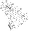
图1为实施例1的煤矿井下突水预警监测装置的结构示意图;Fig. 1 is the structural representation of the water inrush early warning monitoring device in the coal mine of
图2为实施例1的煤矿井下突水预警监测装置的局部结构剖视图;Fig. 2 is the partial structure sectional view of the water inrush early warning monitoring device in the coal mine of
图3为图2中A处的结构放大图;Figure 3 is an enlarged view of the structure at A place in Figure 2;
图4为图2中B处的结构放大图;Figure 4 is an enlarged view of the structure at B in Figure 2;
图5为实施例1的煤矿井下突水预警监测装置中导流罩的结构示意图;5 is a schematic structural diagram of a diversion hood in the coal mine underground water inrush early warning and monitoring device of
图6为实施例1的煤矿井下突水预警监测装置的隔板与第二滤板位置关系示意图;6 is a schematic diagram of the positional relationship between the clapboard and the second filter plate of the coal mine underground water inrush early warning monitoring device of
图7为实施例2的矿井突水灾害预警的组合传感器监测装置的结构主视图;7 is a structural front view of the combined sensor monitoring device for mine water inrush disaster early warning according to
图8为实施例2的矿井突水灾害预警的组合传感器监测装置的结构仰视图;8 is a bottom view of the structure of the combined sensor monitoring device for mine water inrush disaster early warning according to
图9为实施例2的矿井突水灾害预警的组合传感器监测装置的结构左视图;9 is a left side view of the structure of the combined sensor monitoring device for early warning of mine water inrush disaster according to
图10为图9中A-A剖视图;Fig. 10 is A-A sectional view in Fig. 9;
图11为实施例3的水仓水位监测装置的结构主视图;11 is a structural front view of the water tank water level monitoring device of
图12为实施例3的水仓水位监测装置的结构俯视图;12 is a top view of the structure of the water tank water level monitoring device of
图13为实施例3的水仓水位监测装置的结构右视图;Fig. 13 is the structural right side view of the sump water level monitoring device of
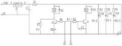
图14为实施例3的水仓水位监测装置的水位探测模块的电路图。14 is a circuit diagram of a water level detection module of the water tank water level monitoring device of the third embodiment.
附图标记:Reference number:
1、导流罩;101、导流槽;102、进水孔;2、第一滤板;3、安装筒;4、第二滤板;5、第一安装台;6、电机;7、第一转动轴;8、第一锥齿轮;9、第二锥齿轮;10、第二转动轴;11、第三转动轴;12、转动柱;13、第一螺旋叶片;14、第二螺旋叶片;15、水质传感器;16、中央控制器;17、声光报警器;18、安装罩;19、固定架;20、固定板;21、震动传感器;22、安装板;23、固定台;24、螺杆;25、旋钮;26、导向杆;27、连接板;28、球形罩;29、固定杆;30、第二安装台;31、第三锥齿轮;32、隔板;33、可调支腿;34、机架;35、连接筒;36、螺母;37、旋转筒;38、伺服驱动器;39、第一支柱;40、顶座;41、伸缩电缸;42、升降板;43、基板;44、转臂;45、探杆;46、中心轴;47、第二支柱;48、直线轴承;49、导柱;50、滚珠导向轴;51、免键轴衬;52、联轴器;53、轴承;54、浮动接头;55、轴承压盖;56、支撑腿;57、安装框架;58、第一合页;59、多色指示灯;60、电源继电器转换箱;61、磁吸搭扣;62、高音报警模块;63、水位探测模块;64、一级水位探头;65、二级水位探头;66、左半防护门;67、右半防护门;68、铁片;69、第二合页;70、把手;71、第一报警喇叭;72、第二报警喇叭。1. Diversion cover; 101. Diversion groove; 102. Water inlet; 2. First filter plate; 3. Installation cylinder; 4. Second filter plate; 5. First installation platform; 6. Motor; 7. 1st rotation shaft; 8, first bevel gear; 9, second bevel gear; 10, second rotation shaft; 11, third rotation shaft; 12, rotation column; 13, first screw blade; 14, second screw Blade; 15. Water quality sensor; 16. Central controller; 17. Sound and light alarm; 18. Installation cover; 19. Fixing frame; 20. Fixing plate; 21. Vibration sensor; 22. Mounting plate; 23. Fixing table; 24, screw; 25, knob; 26, guide rod; 27, connecting plate; 28, spherical cover; 29, fixed rod; 30, second installation platform; 31, third bevel gear; 32, partition plate; 33, optional Adjusting outriggers; 34, frame; 35, connecting cylinder; 36, nut; 37, rotating cylinder; 38, servo driver; 39, first pillar; 40, top seat; 41, telescopic electric cylinder; 42, lifting plate; 43, base plate; 44, rotating arm; 45, probe rod; 46, central shaft; 47, second pillar; 48, linear bearing; 49, guide column; 50, ball guide shaft; 51, keyless bushing; 52, Coupling; 53, bearing; 54, floating joint; 55, bearing gland; 56, support leg; 57, mounting frame; 58, first hinge; 59, multi-color indicator light; 60, power relay conversion box; 61. Magnetic hasp; 62. Treble alarm module; 63. Water level detection module; 64. First-level water level probe; 65. Second-level water level probe; sheet; 69, the second hinge; 70, the handle; 71, the first alarm horn; 72, the second alarm horn.
具体实施方式Detailed ways
为使本发明的目的、技术方案和优点更加清楚明了,下面结合具体实施方式并参照附图,对本发明进一步详细说明。应该理解,这些描述只是示例性的,而并非要限制本发明的范围。此外,在以下说明中,省略了对公知结构和技术的描述,以避免不必要地混淆本发明的概念。In order to make the objectives, technical solutions and advantages of the present invention clearer, the present invention will be further described in detail below with reference to the specific embodiments and the accompanying drawings. It should be understood that these descriptions are exemplary only and are not intended to limit the scope of the invention. Also, in the following description, descriptions of well-known structures and techniques are omitted to avoid unnecessarily obscuring the concepts of the present invention.
实施例1Example 1
本发明的一个具体实施例,如图1-5所示,公开了一种煤矿井下突水预警监测装置,包括水质监测机构、中央控制器16、声光报警器17和固定架19;其中,水质监测机构包括导流罩1、安装筒3、转动柱12、第一螺旋叶片13、水质传感器15和安装罩18;导流罩1设置有多个进水孔102,且转动安装于安装筒3的进水端;第一螺旋叶片13设置在转动柱12上,转动柱12和第一螺旋叶片13同轴设置在安装筒3内侧,第一螺旋叶片13和安装筒3内壁之间设置有流水通道;安装台组件设置在安装筒3外周面上,安装台组件与安装罩18连接,具体而言,安装罩18通过安装台组件固定在安装筒3的外周面上,安装台组件包括一个第一安装台5和多个第二安装台30,第一安装台5和第二安装台30均为不锈钢材质,第一安装台5上设置有用于驱动导流罩1和转动柱12转动的驱动机构,第二安装台30上设置有用于插入安装筒3内部的水质传感器15,水质传感器15与中央控制器16通讯连接,中央控制器16设置在安装罩18内部,中央控制器16与驱动机构和声光报警器17分别控制连接,声光报警器17设置在安装罩18顶部,安装罩18设置在固定架19上。A specific embodiment of the present invention, as shown in Figures 1-5, discloses a coal mine underground water inrush early warning and monitoring device, including a water quality monitoring mechanism, a
本实施例中,安装筒3内设有过滤组件,过滤组件包括第一滤板2和第二滤板4,第一滤板2和第二滤板4沿水流方向依次同轴设置于安装筒3的两端,导流罩1、第一滤板2、安装筒3和第二滤板4沿水流方向依次同轴设置,导流罩1与第一滤板2转动连接,导流槽101终点端与第一滤板2外周面对齐,第一滤板2、安装筒3和第二滤板4依次连接,转动柱12与第二滤板4转动连接。通过在安装筒3的两端设置滤板,能够防止矿井水中的杂质进入安装筒3内,避免安装筒内堵塞,而且防止水流中的碎石颗粒撞击水质传感器,提升水质传感器的使用寿命,保证监测装置的工作可靠性。In this embodiment, the
本发明能在保证水质传感器15正常监测的前提下,对水质传感器15进行安全防护,且能避免导流罩1、第一滤板2和第二滤板4的堵塞情况发生,有利于长时间稳定的进行水质监测,从而能长时间进行煤矿井下突水预警监测。利用固定架19将本装置固定在排水沟旁边,导流罩1、第一滤板2、安装筒3和第二滤板4均被放置在煤矿巷道排水沟内,且不会与排水沟内壁接触。驱动机构驱动导流罩1和转动柱12转动,转动柱12带动第一螺旋叶片13转动。水流进入安装筒3内后,由第二螺旋叶片14对水流进行导流,使水流中的不同成分能够分布均匀,由水质传感器15对水质进行监测,节省监测所需时间,提高监测效率,并通过监测到的矿井水水质成分变化判断是否有地下水或其他层位矿井水涌入,当监测到水中掺杂有涌入的地下水或其他层位矿井水时,向中央控制器16发送信号,启动声光报警器17进行报警,有效提高了预警效率,有利于工作人员及时撤离,有利于保障人员安全。The present invention can safely protect the
在一个可选的实施例中,第一安装台5和第二安装台30均为柱状结构,第一安装台5和第二安装台30均贯穿设置有中心孔,具体而言,第一安装台5设置第一中心孔,第一转轴穿过第一中心孔与电机6输出轴连接;第二安装台30设置第二中心孔,水质传感器15安装于第二中心孔内,水质传感器15的前端伸入至安装筒3的内部。In an optional embodiment, the first installation table 5 and the second installation table 30 are both columnar structures, and both the first installation table 5 and the second installation table 30 are provided with a central hole therethrough. The
在一个可选的实施例中,安装罩18为密封的箱体结构,包括顶壁、底壁和侧壁,顶壁、底壁和侧壁一体成型或密封拼接而成。中央控制器16、电机6安装在安装罩18的内部空间。In an optional embodiment, the
在一个可选的实施例中,安装罩18的底壁设有第一安装口和第二安装口,第一安装台5和第二安装台30的第一端与安装筒3外周面固定连接,第一安装台5和第二安装台30的第二端均位于安装罩18的内部空间,第一安装台5通过密封圈密封安装于第一安装口,第二安装台30通过密封圈密封安装于第二安装口;第一安装台5的外周壁设置第一凸台,第一凸台用于固定支撑第一安装口,第二安装台30的外周壁设置第二凸台,第二凸台用于固定支撑第二安装口,密封圈设置在第一凸台和第二凸台上实现密封。安装筒3外周面设置第一通孔和第二通孔,安装筒3的第一通孔与第一安装台5的第一中心孔对应,允许第一转轴穿过,第一转轴与第一中心孔密封转动连接;安装筒3的第二通孔与第二安装台30的第二中心孔对应,水质传感器15装入安装筒3的第二通孔和第二安装台30的第二中心孔,水质传感器15的前端穿过安装筒3的第二通孔伸入到安装筒3内。In an optional embodiment, the bottom wall of the
考虑到传统水质传感器15均为刚性安装,一旦完成安装在测试过程中是无法进行移动的,一旦有颗粒物撞击容易损坏水质传感器15。本实施例中,进入安装筒3内的矿井水流中不可避免夹带一定粒径的颗粒物杂质,由于安装筒3内的矿井水的流水较高,较高速度的颗粒物杂质撞击水质传感器15,容易导致水质传感器15损坏。因此,基于上述问题,本实施例中第二安装台30的一个优选实施方式,水质传感器15采用柔性安装的方式,第二安装台30的第二中心孔的孔径大于水质传感器15的外径尺寸,第二中心孔内安装减震件,也即水质传感器15通过减震件安装于第二中心孔内,减震件能够降低矿井水中颗粒物杂质对水质传感器15的撞击损害,提升水质传感器15的使用寿命,保证监测结果的连续性与可靠性。Considering that the traditional
具体而言,减震件的一种结构为弹性充填物,如弹性橡胶,第二中心孔的孔径大于水质传感器15的外径,在水质传感器15与第二中心孔的环形空间内充填弹性橡胶,通过充填弹性橡胶不仅能够起到减震的作用,而且能够起到密封的作用。Specifically, a structure of the shock absorbing member is an elastic filler, such as elastic rubber, the diameter of the second central hole is larger than the outer diameter of the
具体而言,减震件的另一种结构为弹簧,水质传感器15与第二中心孔的环形空间内安装多个弹簧,水质传感器15利用多个弹簧,优选4个弹簧固定在第二中心孔内,弹簧的第一端固定在第二中心孔的孔壁,弹簧的第二端抵靠在水质传感器15的外周壁,或者,水质传感器15的下部套设连接环,弹簧的第二端与连接环连接。自然状态下,弹簧均为拉伸状态,水质传感器15位于第二中心孔的中心线上,当矿井水中的颗粒撞击水质传感器15时,水质传感器15会向下游方向摆动,挤压下游方向的弹簧,并在上游弹簧拉力作用下使水质传感器15复位,此过程实现减震效果。Specifically, another structure of the shock absorber is a spring, and a plurality of springs are installed in the annular space between the
为了进一步降低矿井水流中夹带的颗粒物撞击水质传感器导致损坏的可能性,第二安装台30的第二中心孔的上部孔径小于下部孔径,由上向下,第二中心孔的孔径逐渐变大,第二中心孔的纵向截面呈喇叭状或八字形,第二中心孔的下部空间构成摆动空间,水质传感器15装入第二中心孔后,水质传感器15的上部与第二中心孔的上部通过球铰转动连接,水质传感器15的下部能够在矿井水的冲击下在摆动空间内摆动。In order to further reduce the possibility of damage to the water quality sensor caused by the impact of particulate matter in the mine water flow, the upper aperture of the second central hole of the
在一个可选的实施例中,呈喇叭状或八字形结构的第二中心孔内设置减震件,也即第二中心孔的摆动空间内充填弹性充填物,或者,摆动空间内设置弹簧,第二中心孔的下部的摆动空间允许水质传感器15的下部在小范围内摆动,减震件能够进一步减少撞击损坏,而且能够使水质传感器15及时复位。第二安装台30的第二中心孔设置供水质传感器15的摆动空间,同时摆动空间内设置减震件,将水质传感器15柔性安装,双重防损坏结构能够有效防止因矿井水流中夹带的颗粒物撞击水质传感器导致损坏,提升了监测装置的工作稳定性。In an optional embodiment, a shock absorbing member is arranged in the second central hole having a trumpet-shaped or figure-eight structure, that is, the swing space of the second central hole is filled with an elastic filler, or a spring is arranged in the swing space, The swing space in the lower part of the second central hole allows the lower part of the
在一个可选的实施例中,导流罩1为半球形结构,且罩状凸起的朝向与水流方向相反,导流罩1外周面上设置有导流槽101,导流槽101呈弧线形设置,多个进水孔102均匀设置在导流槽101的槽底。当水流流动至导流罩1处时,水流沿着导流罩1外周面流动,因为康达尔效应,水流易于在半球形罩状结构的导流罩1外表面上流动,易于流至导流槽101内,沿着弧线形的导流槽101流动,并在流动过程中通过进水孔102穿过导流罩1,碎石会在撞击到转动状态下的导流罩1时向外侧流动,不易进入导流槽101和进水孔102内,不易堵塞进水孔102,即便进入导流槽101,也会从导流槽101的终点端流动出去,第一滤板2在保证水流顺畅流动的前提下起到进一步的防护作用。In an optional embodiment, the
在一个可选的实施例中,进水孔102的中心线并不垂直于导流槽101槽底,进水孔102沿轴向逐渐向水流方向倾斜,也即多个进水孔102沿水流的上游至下游方向逐渐向导流罩1轴向倾斜。通过将进水孔102沿轴向逐渐向水流方向倾斜设置,有利于水流流动,能使水流更顺畅的通过进水孔102,进水孔102孔径沿水流方向逐渐增大,碎石等杂物不易堵塞进水孔102。In an optional embodiment, the center line of the
在一个可选的实施例中,进水孔102的孔口边缘处设置有圆角,进一步提高水流流动的顺畅性。In an optional embodiment, the edge of the orifice of the
在一个可选的实施例中,第一滤板2和第二滤板4上均设置有滤孔,且滤孔孔径沿水流方向逐渐增大,第一滤板2上均匀布设多个第一虑孔,第二滤板4上匀布设多个第二虑孔,第一虑孔的孔径小于第二虑孔的孔径,能够进一步防止杂物堵塞。In an optional embodiment, both the
在一个可选的实施例中,煤矿井下突水预警监测装置还设置有防倒灌装置,防倒灌装置拆卸设置在安装筒3内且位于第二滤板4的下游,也就是说,第一滤板2、第二滤板4和防倒灌装置均拆卸设置在安装筒3内且沿水流流向设置,通设置防倒灌装置能够防止下游水流倒灌反向进入安装筒3内,从而有效防止倒灌流水中的杂物堵塞第二滤板,且保证水质传感器15监测结果的准确性。In an optional embodiment, the coal mine underground water inrush early warning and monitoring device is further provided with an anti-backflow device, and the anti-backflow device is disassembled and arranged in the
在一个可选的实施例中,如图6所示,防倒灌装置包括隔板32,隔板32的顶端与安装筒3的内壁转动连接,隔板32的形状与安装筒3的内壁形状相适配,隔板32能够在上游矿井水的冲击下打开,在自身重力或倒灌矿井水的冲击下关闭;隔板32的顶端向上游方向倾斜设置,安装筒3的内壁设置限位部,限位部为环形或椭环形结构,限位部用于限制隔板32只能向限位部的下游方向摆动,隔板32的外沿周边能够与安装筒3内壁上的限位部贴合。自然状态下,隔板32在重力作用下下垂,此时隔板32的迎水面周边与整个限位部密封接触,将安装筒3的出水端与第二滤板4隔开,从而避免下游倒灌的矿井水经安装筒3的出水口反向进入安装筒3内。当上游的矿井流水进入安装筒3内后,依次流经第一滤板2和第二滤板4,经过第二滤板4的流水冲击隔板32,隔板32打开,矿井内流水由安装筒3的出水口正常排出;当上游流水量小时,隔板32在自身重力复位将安装筒3的出水端与第二滤板4隔开,同时能够使安装筒3内始终保持一定的储水量,使得水质传感器15能够监测到水质数据,有助于提升监测效果;当下游发生矿井水倒灌时,倒灌的矿井水冲击隔板32的背水面,能够使隔板32向上游方向迅速复位,及时将安装筒3的出水端与第二滤板4隔开,防止倒灌流水中夹带的杂质堵塞第二滤板4,保证了监测装置的工作稳定性。In an optional embodiment, as shown in FIG. 6 , the anti-backflow device includes a
在一个可选的实施例中,隔板32由上部和下部两部分构成,上部的密度大于下部的密度,上部由密度大的金属材质制成,下部由轻质的塑料或轻质合金制成,此结构设置能够使隔板32的重心靠上,便于在矿井水的冲击下打开。In an optional embodiment, the
在一个可选的实施例中,隔板32的纵向剖面为对称图形,具有纵向对称轴线,隔板32的有效纵向阻挡长度L大于安装筒3的内壁直径D,隔板32安装在安装筒3内后,自然状态下,隔板32的顶端与底端之间的距离为L,隔板32的重心位于隔板32的纵向对称轴线上且距隔板32顶端下方的1/5-1/4L处,此结构设计能够保证隔板32能够在小水流量时也能顺利打开,同时能够在发生下游矿井水倒灌时在第一时间回摆复位,防止倒灌的矿井水堵塞第二滤板4。同时,隔板32的纵向对称轴线与竖直方向呈5-8°夹角,此角度设置避免因角度过大隔板32打开难度大、角度过小无法使安装筒3内储存一定量矿井水无法在低水量时实现水质传感器监测结果的连续性。In an optional embodiment, the longitudinal section of the
在一个可选的实施例中,隔板32的迎水面为凸形曲面,凸向上游,隔板32的背水面为凹形曲面,从流体力学角度来看,凸形曲面能够增大冲击隔板32时水流的无效损失,而凹形曲面能够降低冲击阀片时水流的无效损失。当水流冲击隔板32的迎水面时,凸形曲面能够延缓隔板32打开,增大开启难度,使安装筒3内储存有一定量的矿井水;当发生矿井水倒灌时,倒灌的矿井水直接冲击隔板32背水面一侧,由于凹形曲面能够增强关闭隔板32的效果,能够进一步缩短隔板32向上游方向快速复位的时间,及时将安装筒3的出水端与第二滤板4隔开,防止倒灌流水中夹带的杂质堵塞第二滤板4,从而保证了监测装置的工作稳定性。In an optional embodiment, the upstream surface of the
在一个可选的实施例中,隔板32的背水面设有水位传感器,当发生矿井水倒灌时,隔板32复位闭合,将安装筒3的出水端与第二滤板4隔开,此时水位传感器监测到隔板32外部的水位变化,当隔板32外部的水位在一定时间内迅速上升至水位阈值高度时,表明监测点下游可能发生井下突水情况,导致矿井水倒灌,此时水位传感器向中央控制器16发送报警信号,中央控制器16控制声光报警器17进行报警,利用震动传感器21、水质传感器15和水位传感器同时进行监测,监测范围更广。In an optional embodiment, a water level sensor is provided on the back surface of the
在一个可选的实施例中,防倒灌装置设置在距离安装筒3的出水口上游30-50cm处,此设计可以避免安装筒3外部流水中的杂物堆积在隔板32的外围,影响隔板32的正常打开与闭合。In an optional embodiment, the anti-backflow device is arranged at a distance of 30-50 cm upstream from the water outlet of the
在一个可选的实施例中,驱动机构包括电机6、第一转动轴7、第一锥齿轮8、第二锥齿轮9、第三锥齿轮31、第二转动轴10、第三转动轴11、球形罩28和固定杆29,电机6设置在第一安装台5上,电机6与第一转动轴7驱动连接,第一转动轴7竖直设置,第一转动轴7转动设置在第一安装台5上,第一转动轴7底端与第一锥齿轮8连接,第一锥齿轮8、第二锥齿轮9和第三锥齿轮31均位于球形罩28内侧,第一锥齿轮8与第二锥齿轮9和第三锥齿轮31同时啮合连接,第二锥齿轮9和第三锥齿轮31沿安装筒3轴向并排设置,第二转动轴10和第三转动轴11均与安装筒3同轴设置,第二转动轴10和第三转动轴11均转动设置在球形罩28上,第二转动轴10贯穿第一滤板2,第二转动轴10两端分别与导流罩1和第二锥齿轮9连接,第三转动轴11两端分别与第三锥齿轮31和转动柱12连接,球形罩28设置在固定杆29上,固定杆29设置在安装筒3内壁上。In an optional embodiment, the driving mechanism includes a
需要说明的是,电机6能驱动第一转动轴7转动,第一转动轴7带动第一锥齿轮8转动,第一锥齿轮8带动第二锥齿轮9和第三锥齿轮31转动,第二锥齿轮9通过第二转动轴10带动导流罩1转动,第三锥齿轮31通过第三转动轴11带动转动柱12转动,从而实现第一螺旋叶片13的转动,通过一个电机6即能实现导流罩1和第一螺旋叶片13的转动,结构紧凑,能量利用率高,制造和使用成本低。It should be noted that the
在一个可选的实施例中,安装筒3内壁上设置有第二螺旋叶片14,第一螺旋叶片13和第二螺旋叶片14共同对水流进行导流,使水流能更稳定均衡的流通至水质传感器15的监测端,第二螺旋叶片14位于第一螺旋叶片13外侧,第一螺旋叶片13和第二螺旋叶片14沿安装筒3径向之间设置有间隔通道,能避免转动的第一螺旋叶片13和静止的第二螺旋叶片14之间发生干涉。In an optional embodiment, the inner wall of the
在一个可选的实施例中,水质传感器15沿水流方向并排设置有两个,当两个水质传感器15均监测到水质异常时,进行报警,避免因一个水质传感器15故障导致的误报警,水质传感器15底端靠近第二螺旋叶片14前侧表面设置,水流能更均衡的流动至水质传感器15底端,有利于保障监测准确度。In an optional embodiment, two
在一个可选的实施例中,固定架19为U形结构,且U形开口朝下设置,固定架19两端底部均设置有固定钉,便于方便的将本装置固定在排水沟旁边。In an optional embodiment, the fixing
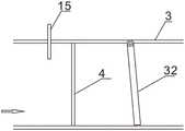
在一个可选的实施例中,煤矿井下突水预警监测装置还包括震动监测机构,震动监测机构固定于固定架19上与煤矿巷道内壁接触,用于监测煤矿巷道的振动。具体而言,震动监测机构包括固定板20、震动传感器21、安装板22、固定台23、螺杆24、旋钮25和导向杆26,固定板20设置在固定架19上,震动传感器21设置在安装板22上,震动传感器21与中央控制器16通讯连接,固定台23与安装板22连接,螺杆24一端与固定台23转动连接,螺杆24另一端与旋钮25连接,螺杆24贯穿固定板20并与固定板20螺纹连接,导向杆26与螺杆24并排设置,导向杆26端部与安装板22连接,导向杆26滑动设置在固定板20上。In an optional embodiment, the coal mine underground water inrush early warning monitoring device further includes a vibration monitoring mechanism. The vibration monitoring mechanism is fixed on the fixing
需要说明的是,通过旋转旋钮25能带动螺杆24转动,螺杆24带动固定台23移动,固定台23带动安装板22移动,导向杆26对安装板22的移动方向进行导向,震动传感器21随安装板22移动,将震动传感器21调整至与煤矿巷道内壁接触的位置,利用震动传感器21监测巷道的振动,当监测到巷道内壁发生振动时,表明煤矿有可能发生井下突水情况,震动传感器21向中央控制器16发送信号,中央控制器16控制声光报警器17进行报警,利用震动传感器21和水质传感器15同时进行监测,监测范围更广。It should be noted that, by rotating the
在一个可选的实施例中,导向杆26远离安装板22的一端连接有连接板27,螺杆24贯穿连接板27,连接板27能防止工人调节震动传感器21时被导向杆26端部划伤,更加安全。In an optional embodiment, one end of the
利用本实施例的煤矿井下突水预警监测装置对煤矿井下进行突水预警监测,包括如下步骤:Using the coal mine underground water inrush early warning and monitoring device of the present embodiment to carry out water inrush early warning monitoring in the coal mine, including the following steps:
S1、将煤矿井下突水预警监测装置放到煤矿巷道的排水沟中,利用固定架19固定本装置,导流罩1朝前设置,导流罩1、第一滤板2、安装筒3和第二滤板4在水中浮空设置,水流能沿着导流罩1外表面流动;S1, put the coal mine underground water inrush early warning monitoring device into the drainage ditch of the coal mine roadway, use the fixing
S2、启动驱动机构和水质传感器15,驱动机构驱动导流罩1和转动柱12转动,转动柱12带动第一螺旋叶片13转动,碎石在流通至导流罩1处时,会被导流罩1撞击出去,不易造成进水孔102的堵塞,水流在流动至第一螺旋叶片13处时,利用第一螺旋叶片13对水进行导流,并使水中的物质成分均匀分布;S2. Activate the driving mechanism and the
S3、水通过导流槽101和进水孔102进入导流罩1内侧,并依次通过第一滤板2、安装筒3和第二滤板4,保证了水流的流通顺畅性;S3, the water enters the inside of the
S4、水质传感器15对进入安装筒3内的水进行检测,水流能均衡的流动至水质传感器15处,未发生突水时,水质检测结果若为正常的煤系地层的水,水质传感器15将检测结果发送至中央控制器16,声光报警器17不报警,提示为煤系地层的水;当水质传感器15监测到水中掺杂有因井下突水而渗入到排水沟中的物质时,如检测出当前水流中含有奥灰水或老窑水,水质传感器15向中央控制器16发送信号,中央控制器16控制声光报警器17进行声光报警,发出出现奥灰水或老窑水等危险水质提醒,在矿井探水时能及时检测判断出探水的水质,并作出是否有突水的可能,有效进行煤矿井下突水预警,使人员能及时撤离,保障人员安全,能够广泛应用于矿井下地质人员操作使用。S4. The
S5、调整震动监测机构,与煤矿巷道内壁接触,在水质传感器15对进入安装筒3内的水进行检测的同时,震动监测机构实时监测煤矿巷道的振动。具体的,将震动传感器21调整至与煤矿巷道内壁接触的位置,利用震动传感器21监测巷道的振动,当监测到巷道内壁发生振动时,表明煤矿有可能发生井下突水情况,震动传感器21向中央控制器16发送信号,中央控制器16控制声光报警器17进行报警,利用震动传感器21和水质传感器15同时进行监测,监测范围更广。S5. Adjust the vibration monitoring mechanism to be in contact with the inner wall of the coal mine roadway. While the
与现有技术相比,本实施例的煤矿井下突水预警监测装置及方法具有如下有益技术效果:Compared with the prior art, the coal mine underground water inrush early warning monitoring device and method of the present embodiment has the following beneficial technical effects:
1、本发明能在保证水质传感器正常监测的前提下,对水质传感器进行安全防护,且能避免导流罩、第一滤板和第二滤板的堵塞情况发生,有利于长时间稳定的进行水质监测,从而能长时间进行煤矿井下突水预警监测。1. The present invention can protect the water quality sensor safely under the premise of ensuring the normal monitoring of the water quality sensor, and can avoid the blockage of the shroud, the first filter plate and the second filter plate, which is conducive to long-term stable performance. Water quality monitoring, so as to carry out early warning monitoring of underground water inrush in coal mines for a long time.
2、利用固定架将本装置固定在排水沟旁边,导流罩、第一滤板、安装筒和第二滤板均被放置在煤矿巷道排水沟内,且不会与排水沟内壁接触。2. Use the fixing frame to fix the device beside the drainage ditch. The diversion cover, the first filter plate, the installation cylinder and the second filter plate are all placed in the drainage ditch of the coal mine roadway, and will not contact the inner wall of the drainage ditch.
3、驱动机构驱动导流罩和转动柱转动,转动柱带动第一螺旋叶片转动。当水流流动至导流罩处时,水流沿着导流罩外周面流动,因为康达尔效应,水流易于在半球形罩状结构的导流罩外表面上流动,易于流至导流槽内,沿着弧线形的导流槽流动,并在流动过程中通过进水孔穿过导流罩,碎石会在撞击到转动状态下的导流罩时向外侧流动,不易进入导流槽和进水孔内,不易堵塞进水孔,即便进入导流槽,也会从导流槽的终点端流动出去,第一滤板在保证水流顺畅流动的前提下起到进一步的防护作用。3. The drive mechanism drives the shroud and the rotating column to rotate, and the rotating column drives the first spiral blade to rotate. When the water flow flows to the shroud, the water flow flows along the outer peripheral surface of the shroud. Because of the Condall effect, the water flow is easy to flow on the outer surface of the shroud of the hemispherical cover structure, and it is easy to flow into the guide groove. It flows along the arc-shaped diversion groove and passes through the diversion hood through the water inlet hole during the flow process. The gravel will flow to the outside when it hits the diversion hood in the rotating state, and it is not easy to enter the diversion groove and the diversion hood. In the water inlet hole, it is not easy to block the water inlet hole. Even if it enters the diversion groove, it will flow out from the end of the diversion groove. The first filter plate plays a further protective role under the premise of ensuring the smooth flow of water.
4、水流进入安装筒内后,由第二螺旋叶片对水流进行导流,使水流中的不同成分能够分布均匀,由水质传感器对水质进行监测,节省监测所需时间,提高监测效率,并在监测到水中掺杂有从涌入的地下水时,向中央控制器发送信号,启动声光报警器进行报警,有效提高了预警效率,有利于工作人员及时撤离,有利于保障人员安全。4. After the water flow enters the installation cylinder, the water flow is diverted by the second helical blade, so that the different components in the water flow can be evenly distributed, and the water quality is monitored by the water quality sensor, which saves the time required for monitoring and improves the monitoring efficiency. When it is detected that the water is mixed with the influx of groundwater, a signal is sent to the central controller, and the sound and light alarm is activated to give an alarm, which effectively improves the early warning efficiency, helps the staff to evacuate in time, and helps to ensure the safety of the personnel.
实施例2Example 2
矿井突水前会有多种预兆,比如工作面顶板掉渣、冒顶、支架倾倒或折梁断柱、底软膨胀、底膨张裂、采掘面围岩内出现裂缝等现象,然而发生这种明显前兆时,往往在很短时间内就会发生突水或者垮塌灾害,工作人员短时间内无法迅速逃离工作面达到安全地带。在上述前兆的发生初期,巷道内壁以及采煤工作面上煤岩体的裂隙就已发生明显变化,如裂隙数量增多(也即单位面积内裂隙密度增大)、裂隙宽度变大、裂隙长度变长,而且多数情况裂隙内还会有水渗出,然而上述这些特征的变化程度相对较小,往往肉眼无法直接判断,现有监测装置往往只监测顶板、底板、巷道侧壁表面的裂隙发育,并未对岩体内的裂隙进行监测,而透水前的煤岩裂隙是由内向外发育的,能够及时监测到煤岩体内部裂隙发育变化情况,对矿井突水的预判具有重要意义。Before the mine water inrush, there will be various signs, such as slag falling from the roof of the working face, roof fall, support dumping or broken beams and columns, bottom soft expansion, bottom expansion cracks, cracks in the surrounding rock of the mining face, etc. However, this phenomenon occurs. When there are obvious precursors, water inrush or collapse disasters often occur in a very short period of time, and workers cannot quickly escape from the working face to reach a safe area in a short period of time. In the early stage of the occurrence of the above-mentioned precursors, the fissures of the inner wall of the roadway and the coal-rock mass on the coal mining face have changed significantly, such as the increase in the number of fissures (that is, the increase in the density of fissures per unit area), the increase in the width of the fissures, and the change in the length of the fissures. In most cases, there will be water seepage in the cracks. However, the degree of change of these characteristics is relatively small, and it is often impossible to directly judge with the naked eye. The fissures in the rock mass were not monitored, but the coal rock fissures before water permeation developed from the inside to the outside, and the development and changes of the internal fissures in the coal rock mass can be monitored in time, which is of great significance for the prediction of mine water inrush.
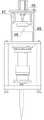
基于上述分析,本发明的又一具体实施例,公开了一种矿井突水灾害预警的组合传感器监测装置,如图7至图10所示,包括机架34、伸缩机构、旋转机构和探杆45,伸缩机构、旋转机构固定设于机架34上,伸缩机构与旋转机构连接,旋转机构与探杆45连接,伸缩机构用于驱动旋转机构沿伸缩方向移动,旋转机构用于驱动探杆45旋转并固定在指定旋转角度位置;探杆45的外周上安装有组合传感器。Based on the above analysis, another specific embodiment of the present invention discloses a combined sensor monitoring device for early warning of mine water inrush disaster, as shown in Figs. 45. The telescopic mechanism and the rotating mechanism are fixed on the
在一个可选的实施例中,探杆45的前端安装有摄影机,探杆45伸入检测孔过程中,摄影机用于对检测孔的孔壁进行拍摄,并获取检测孔孔壁的裂隙图像及裂隙参数。In an optional embodiment, a camera is installed at the front end of the
在一个可选的实施例中,探杆45为中空结构,摄影机拆卸安装在探杆45的前端,摄影机的光导纤维缆布置在探杆45的中空结构中,探测过程与矿用钻孔成像仪对钻孔进行探测的过程相同。通过检测孔内的裂隙变化情况,预判矿井突水的可能,使得监测结果更直观、可靠。In an optional embodiment, the
本实施例中,摄影机可以采用矿用钻孔成像仪的摄像机,也就是说,采用现有矿用钻孔摄像机即可,摄像机的主机由密封防水、转向、卷片、照明摄影、光路反射与方向指示等五大系统组成,摄像机的所有元件均安装在内径为毫米的防水外壳内,摄像头通过光导纤维缆与地面控制器连接,拍摄过程由地面控制器自动操纵拍摄动作。In this embodiment, the camera can be the camera of the mine borehole imager, that is to say, the existing mine borehole camera can be used. It consists of five major systems including direction indication. All components of the camera are installed in a waterproof casing with an inner diameter of millimeters. The camera is connected to the ground controller through an optical fiber cable. The ground controller automatically controls the shooting action during the shooting process.
在一个可选的实施例中,探杆45上的组合传感器包括湿度传感器、水位传感器。利用湿度传感器检测孔内的湿度参数,根据多次湿度监测结果参数的变化情况,对矿井突水进行预判;利用水位传感器检测孔内是否有积水,一旦发现检测孔内有积水,且水位升高,则表明已发生渗水,有突水风险。根据检测孔内湿度参数、裂隙参数以及水位参数信息,综合判断检测孔内是否发生渗水,例如,当检测孔内湿度明显增大、裂隙参数变化达到渗水的阈值范围,且监测到检测孔内有积水,水位有上升的趋势,由此可判断出检测孔内的裂隙已发生渗水,有突水的可能。In an optional embodiment, the combined sensors on the
在一个可选的实施例中,组合传感器还包括温度传感器、水质传感器,温度传感器用于检测检测孔内的温度,如果检测孔内发生渗水,水质传感器检测渗水的水质,通过温度参数、水质参数对矿井突水结果预判提供辅助参考。In an optional embodiment, the combined sensor further includes a temperature sensor and a water quality sensor. The temperature sensor is used to detect the temperature in the detection hole. If water seepage occurs in the detection hole, the water quality sensor detects the water quality of the seepage water. It provides an auxiliary reference for the prediction of mine water inrush results.
需要说明的是,本实施例中根据各监测参数作出突水预警监测结果,可以由经验丰富的技术人员判断,也可以由计算机处理系统自动判断。优选采用计算机处理系统自动判断,计算机处理系统基于监测到的温度、湿度、裂隙及水位、水质等参数,与预设的各参数阈值范围比对,利用模糊综合评判法、人工神经网络、灰色关联分析等方法,对矿井突水进行预判,并将预判结果显示在远端监控屏幕上,一旦发生突水预判,则发出警报。It should be noted that, in this embodiment, the water inrush early warning monitoring results are made according to various monitoring parameters, which can be judged by experienced technicians, or can be judged automatically by a computer processing system. It is preferable to use a computer processing system for automatic judgment. The computer processing system compares the monitored temperature, humidity, fissures, water level, water quality and other parameters with the preset threshold ranges of each parameter, and uses fuzzy comprehensive evaluation method, artificial neural network, gray correlation Analysis and other methods are used to predict mine water inrush, and the results of the prediction will be displayed on the remote monitoring screen. Once the prediction of water inrush occurs, an alarm will be issued.
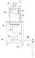
本实施例中,伸缩机构包括第一支柱39、顶座40、伸缩电缸41、升降板42、基板43,中心轴46、第二支柱47、直线轴承48和导柱49,顶座40通过第一支柱39安装在机架34的上方,伸缩电缸41固定安装在顶座40上,导柱49顶端固定安装在顶座40上,直线轴承48安装在导柱49上,升降板42固定安装在直线轴承48上且伸缩电缸41伸缩杆末端通过浮动接头54安装在升降板42上,基板43通过第二支柱47安装在升降板42下方。In this embodiment, the telescopic mechanism includes a
旋转机构包括连接筒35、螺母36、旋转筒37、伺服驱动器38、转臂44、滚珠导向轴50、免键轴衬51、联轴器52、轴承53、浮动接头54和轴承压盖55;其中,中心轴46的顶端通过轴承53安装在基板43安装孔里,轴承压盖55通过螺钉固定安装在基板43底面上且轴承压盖55压在轴承53上,中心轴46下端通过联轴器52与滚珠导向轴50上端连接,伺服驱动器38固定安装在机架34上的中心孔里,旋转筒37顶端通过螺钉安装在伺服驱动器38上,螺母36安装在滚珠导向轴50上且螺母36固定安装在旋转筒37底部,连接筒35通过免键轴衬51固定安装在滚珠导向轴50下端,转臂44的一端固定安装在连接筒35的底面上,探杆45固定安装在转臂44另一端的安装孔里。The rotating mechanism includes a connecting cylinder 35, a nut 36, a rotating cylinder 37, a servo driver 38, a rotating arm 44, a ball guide shaft 50, a keyless bushing 51, a coupling 52, a bearing 53, a floating joint 54 and a bearing gland 55; The top of the center shaft 46 is installed in the mounting hole of the base plate 43 through the bearing 53, the bearing cover 55 is fixedly installed on the bottom surface of the base plate 43 by screws, and the bearing cover 55 is pressed on the bearing 53, and the lower end of the center shaft 46 passes through the coupling. 52 is connected to the upper end of the ball guide shaft 50, the servo driver 38 is fixedly installed in the center hole on the frame 34, the top of the rotating cylinder 37 is installed on the servo driver 38 by screws, the nut 36 is installed on the ball guide shaft 50 and the nut 36 is fixed Installed at the bottom of the rotating cylinder 37, the connecting cylinder 35 is fixedly installed on the lower end of the ball guide shaft 50 through the keyless bushing 51, one end of the rotating arm 44 is fixedly installed on the bottom surface of the connecting cylinder 35, and the probe rod 45 is fixedly installed on the other side of the rotating arm 44. in the mounting hole at one end.
在一个可选的实施例中,机架34底部还设有可调支腿33,可调支腿33的高度可调节,可调支腿33的数量为4个,均匀分布在机架34底部四角,通过高度可调节设置,保证装置安装的水平状态。可调支腿33上安装有踏板式单刹车万向轮,当移动至指定位置后,踩踏刹车结构使万向轮锁死,防止在监测过程中移动。In an optional embodiment, the bottom of the
在一个可选的实施例中,伺服驱动器38为中空式结构,轴承53采用双列面对面向心球面球轴承组合而成,中心轴46的顶端设有环形卡槽且环形卡槽里安装有轴用弹性卡圈,轴承压盖55与轴承53之间安装有环形调整垫片。In an optional embodiment, the
需要说明的是,如图7-图10所示的矿井突水灾害预警的组合传感器监测装置,能够实现底板检测孔的检测。当然,可以在结构上进行变换就能够实现巷道顶板、侧壁上检测孔的检测,例如,将伸缩机构、旋转机构和探杆45等相关部件在竖直方向上翻转180°设置就能实现顶板检测孔的检测,将伸缩机构、旋转机构和探杆45等相关部件翻转90°设置就能实现巷道侧壁检测孔的检测,对此实施例不再赘述。It should be noted that the combined sensor monitoring device for early warning of mine water inrush disaster as shown in Figures 7-10 can realize the detection of the detection hole of the floor. Of course, the detection of the detection holes on the roof and side walls of the roadway can be realized by changing the structure. For example, the roof can be realized by turning the related components such as the telescopic mechanism, the rotating mechanism and the
以图7-图10所示的矿井突水灾害预警的组合传感器监测装置对底板上检测孔检测为例,矿井突水灾害预警监测方法,包含以下步骤:Taking the detection of the detection holes on the bottom plate by the combined sensor monitoring device for early warning of mine water inrush disaster shown in Figures 7-10 as an example, the mine water inrush disaster early warning and monitoring method includes the following steps:
a)采用钻机根据需要检测需求钻取多组检测孔,每组检测孔包括多个检测孔,每组的检测孔均匀分布在同一圆周上,优选每组检测孔的数量为4-6个,检测孔的深度在0.5-2m之间,并将矿井突水灾害预警的组合传感器监测装置固定在每组检测孔所在圆周的中心位置。在矿井不同位置布设多组检测孔,利用多个监测装置以实现矿井内多位置同步监测。a) Use a drilling rig to drill multiple groups of inspection holes according to the inspection requirements. Each group of inspection holes includes multiple inspection holes, and the inspection holes of each group are evenly distributed on the same circumference. Preferably, the number of inspection holes in each group is 4-6. The depth of the detection holes is between 0.5-2m, and the combined sensor monitoring device for mine water inrush disaster warning is fixed at the center of the circle where each group of detection holes is located. Multiple sets of detection holes are arranged at different positions in the mine, and multiple monitoring devices are used to realize simultaneous monitoring of multiple positions in the mine.
b)调整可调支腿33使得机架34顶面保持水平,使旋转筒37的中心线通过检测孔所在圆周的圆心,伺服驱动器38转动带动旋转筒37上的连接筒35转动,从而带动转臂44转动到当前检测孔处。b) Adjust the
c)伸缩电缸41向下运动,驱动升降板42沿着导柱49向下运动,进而带动基板43上的中心轴46向下运动,从而使得滚珠导向轴50上的转臂44向下运动,将探杆45由当前检测孔的孔口插入到检测孔的孔底,插入过程中探杆45上的摄像机、传感器获取检测孔内裂隙、湿度、水位等参数信息。c) The telescopic
d)测量完成后,伸缩电缸41带动探杆45上升到初始位置处,然后,伺服驱动器38带动转臂44上的探杆转动至下一个检测孔处,对下一检测孔进行检测。d) After the measurement is completed, the telescopic
e)重复步骤c)和d)检测完所有的检测点。经过一定时间间隔后,对所有检测点重新进行再次监测,按照预设的时间间隔(如每隔2小时)对检测点进行重复监测,保证监测的持续性。e) Repeat steps c) and d) to detect all the detection points. After a certain time interval, all detection points are re-monitored, and the detection points are repeatedly monitored according to a preset time interval (eg, every 2 hours) to ensure the continuity of monitoring.
在步骤c中,在探杆45伸入检测孔过程中,摄影机对检测孔的孔壁进行拍摄,得到检测孔孔壁的三维虚拟柱状图和钻孔孔壁展开图,计算机处理单元对摄影机获取的图像进行处理,获得裂隙图像并识别出裂隙参数,裂隙参数包括裂隙数量、裂隙密度以及裂隙长度参数,并记录该检测孔的编号以及检测批次,计算机处理单元处理后的裂隙图像、检测孔内裂隙参数传输至远程控制端,并显示在远程控制端的屏幕上;湿度传感器检测孔内的湿度参数、水位传感器检测孔内是否有积水和水位变化信息,检测孔内的湿度、水位参数信息传输至远程控制端,并显示在远程控制端的屏幕上。In step c, when the
利用摄影机对布置在矿井内的所有检测孔进行探测,通过间隔多次检测孔内裂隙的发育变化情况,若同一检测孔多次监测结果显示:裂隙变宽、变长、密度变大,且变化程度达到一定时,也即预先设置裂隙参数变化阈值,当裂隙参数变化达到阈值范围时,则可能发生突水;若不同位置检测孔的监测结果具有规律性变化,且整体上裂隙监测结果显示:裂隙变宽、变长、密度变大,且至少有部分检测孔的裂隙变化程度达到预先设置的裂隙参数变化阈值范围,则可以预判可能发生突水的位置,对可能发生的位置进行处理,如注浆锚索锚固封堵裂隙等措施,以避免发生突水事件或降低突水事件造成的损失。Use the camera to detect all the inspection holes arranged in the mine, and detect the development and changes of the cracks in the holes multiple times at intervals. When the degree of water inrush reaches a certain level, that is to say, the threshold for the change of the fracture parameters is preset. When the change of the fracture parameters reaches the threshold range, water inrush may occur; if the monitoring results of the detection holes at different positions change regularly, and the overall fracture monitoring results show: When the cracks become wider, longer, and denser, and the degree of crack change of at least some of the detection holes reaches the preset crack parameter change threshold range, the location where water inrush may occur can be predicted, and the possible locations can be processed. Measures such as grouting anchor cables, anchoring and plugging cracks, etc., can avoid water inrush events or reduce losses caused by water inrush events.
与现有技术相比,本实施例的矿井突水灾害预警的组合传感器监测装置,具有如下有益效果:Compared with the prior art, the combined sensor monitoring device for mine water inrush disaster early warning of the present embodiment has the following beneficial effects:
1、机架底部设置有可调支腿,可调支腿上安装有踏板式单刹车万向轮,方便了其移动,同时工作时将可调支腿支撑起来,此时万向轮脱离地面接触,从而实现了工作时固定,因而稳定可靠;滚珠导向轴和中心轴都是采用中空结构,因而方便了线缆的布置;采用中空伺服驱动器,实现了中心轴从伺服驱动器中心孔穿出与滚珠导向轴连接,从而实现了在旋转的同时,还可以实现转臂的升降运动;中心轴上端采用双列面对面向心球面球轴承组合且采用环形调整垫调整轴承轴向游隙,从而大大提高了其结构刚性和旋转精度,提高了监测效率;伺服驱动器带动采用滚珠导向轴和螺母整体一起转动,滚珠导向轴上端通过联轴器与中心轴连接,中心轴通过轴承支撑在基板上,从而实现了旋转运动和升降运动的叠加操作;采用伸缩电缸配合滚珠导向轴,提高了其升降运动的精度和升降运动的稳定性;通过旋转和升降运动一次实现了多个检测点的监测,显著提高了其工作效率,节省了操作时间,提升了监测效率。1. Adjustable outriggers are arranged at the bottom of the frame. A pedal-type single-brake universal wheel is installed on the adjustable outrigger, which facilitates its movement. At the same time, the adjustable outrigger is supported during work, and the universal wheel is off the ground at this time. contact, so as to be fixed at work, so it is stable and reliable; the ball guide shaft and the central shaft are both hollow, which facilitates the arrangement of cables; the hollow servo driver is used to realize the central shaft passing through the center hole of the servo driver. The ball guide shaft is connected, so as to realize the lifting motion of the rotating arm while rotating; the upper end of the central shaft adopts a combination of double-row face-to-face radial spherical ball bearings and adopts an annular adjusting pad to adjust the axial clearance of the bearing, thereby greatly improving the Its structural rigidity and rotation accuracy are improved, and the monitoring efficiency is improved; the servo driver drives the ball guide shaft and the nut to rotate together as a whole. The superimposed operation of the rotating motion and the lifting motion is realized; the telescopic electric cylinder is used with the ball guide shaft to improve the accuracy of the lifting motion and the stability of the lifting motion; the monitoring of multiple detection points is realized through the rotation and the lifting motion at one time, which significantly improves the It improves its work efficiency, saves operation time, and improves monitoring efficiency.
2、通过在探杆的前端安装有摄影机,探杆上安装有组合传感器,如湿度传感器、水位传感器,在探杆伸入检测孔过程中,摄影机对检测孔的孔壁进行拍摄,并获取检测孔孔壁的裂隙图像及裂隙参数,湿度传感器检测孔内的湿度参数,水位传感器检测孔内水位信息,根据检测孔内湿度参数、裂隙参数以及水位参数信息,综合判断检测孔内是否发生渗水,例如,当检测孔内湿度明显增大、裂隙参数变化达到渗水的阈值范围,且监测到检测孔内有积水,水位有上升的趋势,由此可判断出检测孔内的裂隙已发生渗水,有突水的可能。综合多参数判断突水可能性,监测结果更加可靠。2. By installing a camera at the front end of the probe rod, and a combination sensor, such as a humidity sensor and a water level sensor, is installed on the probe rod. During the process of the probe rod extending into the detection hole, the camera shoots the hole wall of the detection hole and obtains the detection results. The crack image and crack parameters of the hole wall, the humidity sensor detects the humidity parameters in the hole, and the water level sensor detects the water level information in the hole. For example, when the humidity in the detection hole increases significantly, the change of the fracture parameters reaches the threshold range of water seepage, and it is detected that there is water in the detection hole, and the water level tends to rise, it can be judged that water seepage has occurred in the cracks in the detection hole. There is a possibility of water inrush. The possibility of water inrush can be judged comprehensively with multiple parameters, and the monitoring results are more reliable.
实施例3Example 3
本发明的又一具体实施例,公开了一种水仓水位监测装置,水仓水位监测装置设置在水仓内,用于实时监测水仓内的水位,通过水仓内的水位变化情况判断矿井是否发生突水以及水仓内水量的大小,并及时发出突水警报,矿区人员可根据水仓内水量大小作出后续抽水、设备抢救措施。Another specific embodiment of the present invention discloses a water silo water level monitoring device. The water silo water level monitoring device is arranged in the water silo and is used to monitor the water level in the water silo in real time, and judge the mine according to the change of the water level in the water silo. Whether there is a water inrush and the size of the water volume in the water tank, and a water inrush alarm will be issued in time, and the mining personnel can take follow-up water pumping and equipment rescue measures according to the water volume in the water tank.
如图11至图13所示,水仓水位监测装置包括安装框架57、第一合页58、多色指示灯59、电源继电器转换箱60、磁吸搭扣61、高音报警模块62、水位探测模块63、一级水位探头64、二级水位探头65、左半防护门66、右半防护门67、铁片68、第二合页69、把手70、第一报警喇叭71和第二报警喇叭72,多色指示灯59固定安装在安装框架57顶面上,左半防护门66通过第一合页58安装在安装框架57前侧面上,右半防护门67通过第二合页69安装在左半防护门66的右侧面上,铁片68安装在右半防护门67内侧,电源继电器转换箱60、高音报警模块62和水位探测模块63都固定安装在安装框架57内,一级水位探头64和二级水位探头65都通过线缆与水位探测模块63连接,第一报警喇叭71和第二报警喇叭72都安装在安装框架57的右侧面上且第一报警喇叭71和第二报警喇叭72都通过线缆与高音报警模块62连接,磁吸搭扣61固定安装在安装框架57内,电源继电器转换箱60上安装有空气开关。As shown in FIGS. 11 to 13 , the water tank water level monitoring device includes a mounting
在一个可选的实施例中,左半防护门66和右半防护门67上都安装有把手70,方便防护门的开关操作。In an optional embodiment, handles 70 are installed on both the left half
在一个可选的实施例中,安装框架57的底部设有支撑腿56,支撑腿56的高度可调节,支撑腿56的数量为4个,均匀分布在安装框架57底部四角,通过调节支撑腿56的高度,保证装置安装的水平状态。支撑腿56上设置有踏板式单刹车万向轮,当移动至指定水仓内指定位置后,踩踏刹车结构使万向轮锁死,防止水位监测装置在监测过程中移动。In an optional embodiment, the bottom of the
在一个可选的实施例中,多色指示灯59从上到下依次由红灯LED1、黄灯LED2和绿灯LED3组成。In an optional embodiment, the
在一个可选的实施例中,电源继电器转换箱60输出24V本安电。In an optional embodiment, the power
如图14所示,水位探测模块63由三端稳压芯片LM7815、手动报警按钮SB、电阻R1、电阻R2、电阻R3、电阻R4、电阻R5、电阻R6、电阻R7、电容C1、电容C2、电容C3、继电器K1、继电器K2、二极管D1、二极管D2、三极管A1和三极管A2组成,三端稳压芯片LM7815的引脚1与电源继电器转换箱60输出引脚24V连接,三端稳压芯片LM7815的引脚2与电源继电器转换箱60输出引脚0V连接,三端稳压芯片LM7815的引脚3和电容C1上端都与电阻R1左端连接,电阻R1右端、继电器K1线圈上端、二极管D1上端、继电器K2线圈上端、二极管D2上端、电阻R2上端、电阻R3上端和电阻R4上端都与电容C2右端连接,继电器K1线圈下端、二极管D1下端和电阻R7上端都与三极管A1的集电极连接,电阻R7下端与手动报警按钮SB常开触点SB1上端连接,手动报警按钮SB常闭触点SB2上端与三极管A1的发射极连接,三极管A1的基极与电阻R6左端连接,电阻R6右端分别与二级水位探头65和继电器K1常开触点K1-1左端连接,继电器K1常开触点K1-1右端和一级水位探头64都与电阻R5左端连接,电阻R5右端和电容C3上端都与三极管A2的基极连接,继电器K2线圈下端和二极管D2下端都与三极管A2的集电极连接,电阻R2下端与红灯LED1上端连接,电阻R3下端与黄灯LED2上端连接,电阻R4下端与绿灯LED3上端连接,红灯LED1下端与手动报警按钮SB常开触点SB3上端连接,黄灯LED2下端与继电器K2常开触点K2-1上端连接,绿灯LED3下端与继电器K2常闭触点K2-2上端连接,电容C1、手动报警按钮SB常开触点SB1下端、手动报警按钮SB常闭触点SB2下端、电容C3右端、三极管A2的发射极、手动报警按钮SB常开触点SB3下端、继电器K2常开触点K2-1下端、继电器K2常闭触点K2-2下端和电容C2左端都与三端稳压芯片LM7815的引脚2连接。As shown in Figure 14, the water
在一个可选的实施例中,高音报警模块62内安装有继电器K1常开触点K1-2和继电器K2常开触点K2-3,继电器K1常开触点K1-2与第二报警喇叭72串联,继电器K2常开触点K2-3与第一报警喇叭71串联。In an optional embodiment, the high-pitched
在一个可选的实施例中,高音报警模块62内安装有稳压电路和蓄电池。In an optional embodiment, a voltage stabilizing circuit and a battery are installed in the high-pitched
本实施例的水仓水位监测装置的工作过程包含以下步骤:The working process of the water tank water level monitoring device of the present embodiment includes the following steps:
a)电源继电器转换箱60传递来的24V本安电通过三端稳压芯片LM7815稳压成15V本安电,此时绿灯LED3亮;a) The 24V intrinsically safe electricity transmitted from the power
b)当水位到达一级水位探头64时,此时三极管A2的基极和发射极经电阻R5形成回路,三极管A2导通,继电器K2线圈得电,继电器K2常开触点K2-1闭合,黄灯LED2亮,继电器K2常闭触点K2-2断开,绿灯LED3灭,同时继电器K2常开触点K2-3闭合,第一报警喇叭71通电报警;b) When the water level reaches the first-level
c)如果水位继续上涨到达二级水位探头65时,三极管A1的基极和发射极经电阻R6形成回路,三极管A1导通,继电器K1线圈得电,继电器K1常开触点K1-1闭合,同时继电器K1常开触点K1-2闭合,红灯LED1亮,继电器K1常开触点K1-3闭合,第二报警喇叭72通电报警;c) If the water level continues to rise and reaches the secondary
d)当水位降到一级水位探头64和二级水位探头65之间时,三极管A1断开,继电器K1线圈失电,继电器K1常开触点K1-1断开,同时继电器K1常开触点K1-2断开,红灯LED1灭,继电器K1常开触点K1-3断开,第二报警喇叭72失电停止报警;d) When the water level drops between the primary
e)当水位降到一级水位探头64下方时,三极管A2断开,继电器K2线圈失电,继电器K2常开触点K2-1断开,黄灯LED2灭,继电器K2常闭触点K2-2闭合,绿灯LED3亮,同时继电器K2常开触点K2-3断开,第一报警喇叭71失电停止报警。e) When the water level drops below the first-level
具体而言,电源继电器转换箱60传递来的24V本安电通过三端稳压芯片LM7815稳压成15V本安电,此时绿灯LED3亮;当水位到达一级水位探头64时,此时三极管A2的基极和发射极经电阻R5形成回路,三极管A2导通,继电器K2线圈得电,继电器K2常开触点K2-1闭合,黄灯LED2亮,继电器K2常闭触点K2-2断开,绿灯LED3灭,同时继电器K2常开触点K2-3闭合,第一报警喇叭71通电报警;如果水位继续上涨到达二级水位探头65时,三极管A1的基极和发射极经电阻R6形成回路,三极管A1导通,继电器K1线圈得电,继电器K1常开触点K1-1闭合,同时继电器K1常开触点K1-2闭合,红灯LED1亮,继电器K1常开触点K1-3闭合,第二报警喇叭72通电报警;当水位降到一级水位探头64和二级水位探头65之间时,三极管A1断开,继电器K1线圈失电,继电器K1常开触点K1-1断开,同时继电器K1常开触点K1-2断开,红灯LED1灭,继电器K1常开触点K1-3断开,第二报警喇叭72失电停止报警;当水位降到一级水位探头64下方时,三极管A2断开,继电器K2线圈失电,继电器K2常开触点K2-1断开,黄灯LED2灭,继电器K2常闭触点K2-2闭合,绿灯LED3亮,同时继电器K2常开触点K2-3断开,第一报警喇叭71失电停止报警;另外可以通过按下手动报警按钮SB,此时手动报警按钮SB常开触点SB1闭合,继电器K1线圈得电,继电器K1常开触点K1-1闭合,同时继电器K1常开触点K1-2闭合,红灯LED1亮,继电器K1常开触点K1-3闭合,第二报警喇叭72通电报警,手动报警按钮SB常闭触点SB2断开;松开手动报警按钮SB,此时手动报警按钮SB常开触点SB1断开,继电器K1线圈失电,继电器K1常开触点K1-1断开,同时继电器K1常开触点K1-2断开,红灯LED1灭,继电器K1常开触点K1-3断开,第二报警喇叭72失电停止报警,手动报警按钮SB常闭触点SB2闭合。Specifically, the 24V intrinsically safe electricity transmitted from the power
与现有技术相比,本实施例的水仓水位监测装置,结构简单,操作方便,能够实时监测水仓内的水位,根据水仓内的水位变化情况判断矿井是否发生突水,操作方便,监测结果更可靠,当发生突水时水仓水位监测装置能够及时提醒工作人员,预警效果好。安装框架防护门采用折叠式结构,右半防护门可以与左半防护门折叠在一起,使得安装框架内部安装维护更加方便,操作更加方便可靠;同时安装框架底部安装有支撑腿且支撑腿上安装有万向轮,既方便了其移动操作,同时又方便固定。水位探测模块的结构简单,成本低,工作可靠性高。Compared with the prior art, the water silo water level monitoring device of the present embodiment has a simple structure and convenient operation, can monitor the water level in the sump in real time, and judge whether the mine water inrush occurs according to the change of the water level in the sump, and is easy to operate. The monitoring results are more reliable. When the water inrush occurs, the water level monitoring device of the silo can remind the staff in time, and the early warning effect is good. The protective door of the installation frame adopts a foldable structure, and the right half protective door can be folded together with the left half protective door, which makes the installation and maintenance inside the installation frame more convenient, and the operation is more convenient and reliable; at the same time, there are supporting legs installed at the bottom of the installation frame and installed on the supporting legs. There are universal wheels, which not only facilitates its mobile operation, but also facilitates its fixation. The water level detection module has the advantages of simple structure, low cost and high working reliability.
实施例4Example 4
本发明的又一具体实施例,公开了一种矿井突水灾害监测系统,包括实施例1的煤矿井下突水预警监测装置,还包括实施例2的矿井突水灾害预警的组合传感器监测装置、实施例3的水仓水位监测装置中的一者或二者。Another specific embodiment of the present invention discloses a mine water inrush disaster monitoring system, including the coal mine underground water inrush early warning and monitoring device of
在一个可选的实施例中,矿井突水灾害监测系统包括实施例1的煤矿井下突水预警监测装置、实施例2中的矿井突水灾害预警的组合传感器监测装置和实施例3的水仓水位监测装置。In an optional embodiment, the mine water inrush disaster monitoring system includes the coal mine underground water inrush early warning and monitoring device of
与现有技术相比,本实施例的矿井突水灾害监测系统,利用煤矿井下突水预警监测装置的水质监测机构实施监测矿井水水质变化、震动监测机构实时监测煤矿巷道的振动信号,利用水仓水位监测装置实时监测水仓内的水位,通过水仓内的水位变化情况判断是否发生突水,利用矿井突水灾害预警的组合传感器监测装置对巷道钻孔内的温度、裂隙、裂隙渗水以及渗水水质情况进行实时监测,通过对矿井内的排水沟、水仓以及巷道底壁、侧壁等多个位置进行同时监测,且基于矿井水的水质、水位、巷道壁的震动、裂隙及裂隙内渗水情况等多参数对矿井突水灾害进行综合判断,使得监测结果更准确、更可靠,当发生矿井突水时监测系统能够及时提醒工作人员,而且有助于根据报警位置判断突水水源来向,预警效果好。Compared with the prior art, the mine water inrush disaster monitoring system of this embodiment uses the water quality monitoring mechanism of the coal mine underground water inrush early warning and monitoring device to monitor the change of mine water quality, and the vibration monitoring mechanism monitors the vibration signal of the coal mine roadway in real time, and uses the water quality monitoring mechanism to monitor the changes in mine water quality. The silo water level monitoring device monitors the water level in the silo in real time, judges whether water inrush occurs through the change of the water level in the silo, and uses the combined sensor monitoring device for mine water inrush disaster warning to monitor the temperature, fissures, fissures and seepage in the tunnel boreholes. Real-time monitoring of seepage water quality, through simultaneous monitoring of multiple locations such as drainage ditches, water silos, bottom walls and side walls of roadways in the mine, and based on the water quality of mine water, water level, roadway wall vibration, fissures and fissures Multi-parameters such as water seepage can comprehensively judge the mine water inrush disaster, which makes the monitoring results more accurate and reliable. , the warning effect is good.
应当理解的是,本发明的上述具体实施方式仅仅用于示例性说明或解释本发明的原理,而不构成对本发明的限制。因此,在不偏离本发明的精神和范围的情况下所做的任何修改、等同替换、改进等,均应包含在本发明的保护范围之内。此外,本发明所附权利要求旨在涵盖落入所附权利要求范围和边界、或者这种范围和边界的等同形式内的全部变化和修改例。It should be understood that the above-mentioned specific embodiments of the present invention are only used to illustrate or explain the principle of the present invention, but not to limit the present invention. Therefore, any modifications, equivalent replacements, improvements, etc. made without departing from the spirit and scope of the present invention should be included within the protection scope of the present invention. Furthermore, the appended claims of this invention are intended to cover all changes and modifications that fall within the scope and boundaries of the appended claims, or the equivalents of such scope and boundaries.
Claims (10)
Priority Applications (1)
| Application Number | Priority Date | Filing Date | Title |
|---|---|---|---|
| CN202110351971.0ACN113203433B (en) | 2021-03-31 | 2021-03-31 | Coal mine underground water inrush early warning monitoring device and method |
Applications Claiming Priority (1)
| Application Number | Priority Date | Filing Date | Title |
|---|---|---|---|
| CN202110351971.0ACN113203433B (en) | 2021-03-31 | 2021-03-31 | Coal mine underground water inrush early warning monitoring device and method |
Publications (2)
| Publication Number | Publication Date |
|---|---|
| CN113203433A CN113203433A (en) | 2021-08-03 |
| CN113203433Btrue CN113203433B (en) | 2022-06-10 |
Family
ID=77026004
Family Applications (1)
| Application Number | Title | Priority Date | Filing Date |
|---|---|---|---|
| CN202110351971.0AActiveCN113203433B (en) | 2021-03-31 | 2021-03-31 | Coal mine underground water inrush early warning monitoring device and method |
Country Status (1)
| Country | Link |
|---|---|
| CN (1) | CN113203433B (en) |
Families Citing this family (6)
| Publication number | Priority date | Publication date | Assignee | Title |
|---|---|---|---|---|
| CN114737915B (en)* | 2022-04-19 | 2024-02-09 | 安徽理工大学 | Deep mining water burst rock burst control device |
| CN114893250B (en)* | 2022-06-09 | 2023-03-28 | 中国矿业大学 | Coal seam water inrush detection and plugging device and method |
| CN115013065A (en)* | 2022-07-05 | 2022-09-06 | 成都理工大学 | An underground flood alarm system based on water inflow monitoring equipment |
| CN116067411B (en)* | 2023-02-22 | 2025-02-18 | 煤炭科学技术研究院有限公司 | A underground geological disaster monitoring device |
| CN116498389A (en)* | 2023-04-27 | 2023-07-28 | 中国安全生产科学研究院 | Colliery gushing water precursor information monitoring and early warning device and method |
| CN117132751B (en)* | 2023-08-28 | 2024-03-22 | 南京运航科技有限公司 | Portable biological identification image acquisition device and method thereof |
Family Cites Families (5)
| Publication number | Priority date | Publication date | Assignee | Title |
|---|---|---|---|---|
| AU2008100542A4 (en)* | 2007-07-01 | 2008-07-10 | Abeysingha Gunawardena, Samantha Mr | Household waste water screening & diversion method & apparatus capable of separating mostly polluted water from less polluted water using electrical conductivity as the screening method. |
| CN103196964B (en)* | 2013-04-12 | 2014-12-31 | 河北工业大学 | Device and method for detecting performance of functional material activated water |
| CN104678065B (en)* | 2015-03-13 | 2016-05-04 | 山西潞安环保能源开发股份有限公司 | Mine water inrush on-line monitoring intelligent early-warning system |
| CN210572274U (en)* | 2019-08-13 | 2020-05-19 | 生态环境部华南环境科学研究所 | Drainage basin water quality early warning and forecasting system |
| CN211603157U (en)* | 2020-01-19 | 2020-09-29 | 深圳市朗诚科技股份有限公司 | Water quality sensor's mount and water quality monitoring device |
- 2021
- 2021-03-31CNCN202110351971.0Apatent/CN113203433B/enactiveActive
Also Published As
| Publication number | Publication date |
|---|---|
| CN113203433A (en) | 2021-08-03 |
Similar Documents
| Publication | Publication Date | Title |
|---|---|---|
| CN113203433B (en) | Coal mine underground water inrush early warning monitoring device and method | |
| CN104597525B (en) | A kind of ground strong gale puts ball system automatically | |
| CN113653005B (en) | Dykes and dams disaster prevention and reduction device of automated inspection water level | |
| CN115182784A (en) | A combined sensor monitoring device and method for early warning of mine water inrush disaster | |
| CN116486576A (en) | Geological disaster early warning system and early warning method thereof | |
| CN112526640B (en) | A Debris Flow Early Warning Device Based on Rainfall Monitoring | |
| CN111986444A (en) | Railway construction early warning device for safety with typhoon monitoring function | |
| CN220730939U (en) | Natural disaster monitoring and early warning device utilizing Beidou satellite positioning | |
| CN113643514B (en) | Landslide early warning device based on monitoring multiple indexes | |
| CN117475585A (en) | An urban flood disaster monitoring and early warning device | |
| CN220199530U (en) | Novel hydrologic test buoy | |
| CN112697223B (en) | Hydrologic information water level monitoring device | |
| CN116863654A (en) | A geological disaster early warning device and its use method | |
| CN117266247A (en) | Intelligent well lid of water meter well | |
| CN214010482U (en) | Flood situation early warning platform | |
| CN219590547U (en) | Secondary disaster prevention monitoring equipment | |
| CN120467293B (en) | A hydrological monitoring device suitable for flood forecasting | |
| CN218628551U (en) | A water level alarm device | |
| CN223152105U (en) | Regional monitoring alarm device for coal mine | |
| CN219530373U (en) | Flood flow velocity investigation device | |
| CN222477524U (en) | An intelligent drainage system for large-scale deep foundation pits | |
| CN222104846U (en) | A water conservancy intelligent monitoring device | |
| CN222318292U (en) | Pressure measuring tube | |
| CN114483194A (en) | A kind of early warning equipment for water prevention and control in coal mine | |
| CN222862324U (en) | Dewatering well protection device |
Legal Events
| Date | Code | Title | Description |
|---|---|---|---|
| PB01 | Publication | ||
| PB01 | Publication | ||
| SE01 | Entry into force of request for substantive examination | ||
| SE01 | Entry into force of request for substantive examination | ||
| GR01 | Patent grant | ||
| GR01 | Patent grant |