CN113195826B - grinding device - Google Patents
grinding deviceDownload PDFInfo
- Publication number
- CN113195826B CN113195826BCN201980084462.7ACN201980084462ACN113195826BCN 113195826 BCN113195826 BCN 113195826BCN 201980084462 ACN201980084462 ACN 201980084462ACN 113195826 BCN113195826 BCN 113195826B
- Authority
- CN
- China
- Prior art keywords
- grinding
- grinding device
- return
- return channels
- outlet
- Prior art date
- Legal status (The legal status is an assumption and is not a legal conclusion. Google has not performed a legal analysis and makes no representation as to the accuracy of the status listed.)
- Active
Links
Images


Classifications
- D—TEXTILES; PAPER
- D21—PAPER-MAKING; PRODUCTION OF CELLULOSE
- D21D—TREATMENT OF THE MATERIALS BEFORE PASSING TO THE PAPER-MAKING MACHINE
- D21D1/00—Methods of beating or refining; Beaters of the Hollander type
- D21D1/20—Methods of refining
- D21D1/30—Disc mills
- B—PERFORMING OPERATIONS; TRANSPORTING
- B02—CRUSHING, PULVERISING, OR DISINTEGRATING; PREPARATORY TREATMENT OF GRAIN FOR MILLING
- B02C—CRUSHING, PULVERISING, OR DISINTEGRATING IN GENERAL; MILLING GRAIN
- B02C7/00—Crushing or disintegrating by disc mills
- B02C7/11—Details
- B02C7/12—Shape or construction of discs
- D—TEXTILES; PAPER
- D21—PAPER-MAKING; PRODUCTION OF CELLULOSE
- D21D—TREATMENT OF THE MATERIALS BEFORE PASSING TO THE PAPER-MAKING MACHINE
- D21D1/00—Methods of beating or refining; Beaters of the Hollander type
- D21D1/20—Methods of refining
- D21D1/22—Jordans
- D—TEXTILES; PAPER
- D21—PAPER-MAKING; PRODUCTION OF CELLULOSE
- D21D—TREATMENT OF THE MATERIALS BEFORE PASSING TO THE PAPER-MAKING MACHINE
- D21D1/00—Methods of beating or refining; Beaters of the Hollander type
- D21D1/20—Methods of refining
- D21D1/22—Jordans
- D21D1/26—Jordan bed plates
- D—TEXTILES; PAPER
- D21—PAPER-MAKING; PRODUCTION OF CELLULOSE
- D21D—TREATMENT OF THE MATERIALS BEFORE PASSING TO THE PAPER-MAKING MACHINE
- D21D1/00—Methods of beating or refining; Beaters of the Hollander type
- D21D1/20—Methods of refining
- D21D1/30—Disc mills
- D21D1/306—Discs
- Y—GENERAL TAGGING OF NEW TECHNOLOGICAL DEVELOPMENTS; GENERAL TAGGING OF CROSS-SECTIONAL TECHNOLOGIES SPANNING OVER SEVERAL SECTIONS OF THE IPC; TECHNICAL SUBJECTS COVERED BY FORMER USPC CROSS-REFERENCE ART COLLECTIONS [XRACs] AND DIGESTS
- Y02—TECHNOLOGIES OR APPLICATIONS FOR MITIGATION OR ADAPTATION AGAINST CLIMATE CHANGE
- Y02W—CLIMATE CHANGE MITIGATION TECHNOLOGIES RELATED TO WASTEWATER TREATMENT OR WASTE MANAGEMENT
- Y02W30/00—Technologies for solid waste management
- Y02W30/50—Reuse, recycling or recovery technologies
- Y02W30/64—Paper recycling
Landscapes
- Engineering & Computer Science (AREA)
- Food Science & Technology (AREA)
- Paper (AREA)
- Led Devices (AREA)
Abstract
Description
Translated fromChinese本发明涉及一种研磨装置,所述研磨装置用于在形成研磨间隙并且相对彼此旋转的两个研磨面之间研磨水性悬浮的纤维材料,所述研磨面由研磨条和在所述研磨条之间延伸的槽形成,其中,研磨条至少以一个方向分量相对于旋转轴线径向地延伸,并且纤维悬浮液穿流过从径向内部的圆形的入口到径向外部的圆形的出口的研磨间隙。The invention relates to a grinding device for grinding aqueously suspended fibrous material between two grinding surfaces forming a grinding gap and rotating relative to each other, the grinding surfaces being composed of a grinding bar and between the grinding bars Grooves extending between them are formed, wherein the grinding bars extend radially with respect to the axis of rotation at least in one direction component, and the fiber suspension flows through the outlet from the radially inner circular inlet to the radially outer circular outlet Grinding gap.
长久以来就已知的是,对纸浆纤维、即新鲜纸浆和/或废纸纤维进行研磨,以便能够在由其制成的纤维料幅中实现期望的特性、尤其是关于强度、成型和表面的期望的特性。It has long been known to grind pulp fibers, i.e. virgin pulp and/or waste paper fibers, in order to be able to achieve desired properties in the fibrous web produced therefrom, especially with regard to strength, shape and surface properties. desired characteristics.
就在此使用的精磨机而言,由于相对快速的磨损,所以研磨面由可更换的、与相应的支撑面螺纹连接的研磨配件(Mahlgarnitur)构成。为了实现期望的纤维特性、尤其是研磨度,研磨配件必须尽可能匹配于待处理的纤维材料,以便也阻止研磨配件的过度磨损。In the case of the refiner used here, due to the relatively rapid wear, the grinding surfaces consist of replaceable grinding fittings which are screwed to the corresponding support surfaces. In order to achieve the desired fiber properties, in particular the degree of grinding, the grinding accessories must be adapted as closely as possible to the fiber material to be processed in order to also prevent excessive wear of the grinding accessories.
此外,为了提高纤维处理的效率,力求达到可用的研磨面的最佳的使用。Furthermore, in order to increase the efficiency of the fiber treatment, an optimum use of the available grinding surfaces is sought.
本发明所要解决的技术问题在于,改进纤维处理的效率。The technical problem addressed by the invention is to improve the efficiency of fiber treatment.
根据本发明,该技术问题如下地解决,即在至少一个研磨面下方布置多个连接出口与入口的回流通道。纤维悬浮液经由回流通道的回流实现多次处理,并且因此实现更均匀的、更有效的研磨。According to the invention, this technical problem is solved in that a plurality of return channels connecting the outlet and the inlet are arranged below at least one grinding surface. The return flow of the fiber suspension via the return channel enables multiple processing and thus a more uniform and efficient grinding.
此外,因此也可以通过相应的回流顺利地补偿要处理的纤维悬浮液的缺乏。In addition, the lack of fiber suspension to be treated can therefore also be easily compensated by a corresponding return flow.
在此有利的是,数个、优选所有回流通道不具有与研磨间隙的连接。因为从出口回流到入口的纤维悬浮液量完全从出口到达入口,所以可以抵消研磨面的不均匀的磨损。It is advantageous here if several, preferably all, return channels do not have a connection to the grinding gap. Since the quantity of fiber suspension flowing back from the outlet to the inlet passes completely from the outlet to the inlet, uneven wear of the grinding surface can be counteracted.
此外可能有利的是,影响在回流通道中回流的纤维悬浮液量,并且因此影响压力增大。为此,回流通道分别可以具有流动横截面的变窄部,针对特殊的使用情况给变窄部设定尺寸。但备选地,为了主动的调节,回流通道也分别可以具有影响通过量的阀。Furthermore, it may be advantageous to influence the amount of fiber suspension returned in the return channel and thus the pressure increase. For this purpose, the return channels can each have a narrowing of the flow cross-section, which is dimensioned for the particular application. Alternatively, however, the return channels can also each have a valve influencing the throughput for active regulation.
为了阻止在不利的运行状态(如过高的通过量或入口与出口之间的负的压力差)下经由回流通道造成从入口到出口的短路流动,回流通道分别可以具有止回阀,所述止回阀阻止从入口到出口的流动。In order to prevent a short-circuit flow from the inlet to the outlet via the return channel in unfavorable operating states (such as too high a throughput or a negative pressure difference between the inlet and the outlet), the return channel can each have a non-return valve, which A check valve blocks flow from inlet to outlet.
为了支持纤维悬浮液从回流通道流到研磨间隙的入口区域的偏转,在研磨面与在研磨面的下方延伸的回流通道之间的过渡部应该在回流通道的输出端处弯曲地延伸,其中,曲率半径优选是至少4mm。In order to support the deflection of the fiber suspension flow from the return channel to the inlet region of the grinding gap, the transition between the grinding surface and the return channel extending below the grinding surface should run in a curved manner at the outlet of the return channel, wherein The radius of curvature is preferably at least 4 mm.
此外,在出口处,至少在回流通道的前方应该存在流动障碍,流动障碍至少以一个方向分量径向地延伸。通过流动障碍减慢纤维悬浮液在出口处的流动的旋转,从而纤维悬浮液可以更容易地流入回流通道中。Furthermore, at the outlet, at least in front of the return channel, there should be a flow obstacle which extends radially with at least one directional component. The rotation of the flow of the fiber suspension at the outlet is slowed down by the flow barrier, so that the fiber suspension can flow into the return channel more easily.
为了简化回流通道的制造而有利的是,至少具有回流通道的研磨面由多个沿周向并排布置的研磨部段构成,并且数个、优选所有回流通道在相邻的研磨部段之间延伸。这意味着,回流通道由研磨部段的对置的侧壁形成。In order to simplify the production of the return channel, it is advantageous if at least the grinding surface with the return channel is formed from a plurality of grinding segments arranged next to one another in the circumferential direction, and several, preferably all return channels extend between adjacent grinding segments . This means that the return channel is formed by opposing side walls of the grinding section.
也简化的是,仅一个研磨面旋转,并且其他的研磨面固定。在该情况下,仅固定的研磨面应该具有回流通道。It is also simplified if only one grinding surface rotates and the other grinding surface is fixed. In this case, only the stationary grinding surface should have return channels.
本发明可以用于平坦的垂直于旋转轴线延伸的研磨面,但也可以用于锥形的研磨面,在锥形的研磨面的情况下,旋转轴线相当于圆锥轴线。The invention can be used for flat grinding surfaces extending perpendicularly to the axis of rotation, but also for conical grinding surfaces, in which case the axis of rotation corresponds to the axis of the cone.
以下应该借助两个实施例详细阐述本发明。在附图中:The invention will be explained in more detail below with the aid of two examples. In the attached picture:
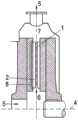
图1示出了穿过盘式-精磨机的示意性的横截面图;并且Figure 1 shows a schematic cross-sectional view through a disc-refiner; and
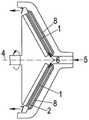
图2示出了穿过锥形的精磨机的示意性的横截面图;Figure 2 shows a schematic cross-sectional view through a conical refiner;
图3示出了出口7处的局部;并且Figure 3 shows a section at the
图4示出了精磨机的入口6处的局部;Figure 4 shows a detail at the
图5示出了穿过两个相邻的研磨部段11的局部横截面图;并且Figure 5 shows a partial cross-sectional view through two
图6示出了研磨部段11的纵向侧面。FIG. 6 shows the longitudinal side of the
根据图1,在研磨装置的壳体中,研磨间隙1由固定的并且与壳体耦合的研磨面和围绕旋转轴线4旋转的研磨面形成,其中,研磨面垂直于旋转轴线4地延伸。According to FIG. 1 , in the housing of the grinding device, the
在此,两个平坦的圆环形的研磨面相互平行地延伸。在研磨面之间的距离大多是可调节的。In this case, the two flat circular grinding surfaces run parallel to one another. The distance between the grinding surfaces is mostly adjustable.
旋转的研磨面在此通过在壳体中可旋转地支承的轴沿旋转方向12运动。该轴由同样在壳体中存在的驱动器驱动。The rotating grinding surface is moved in the direction of
在此处所示的示例中,待研磨的纤维悬浮液5通过径向内部的圆形的入口6进入两个研磨面之间的研磨间隙1。In the example shown here, the
纤维悬浮液5径向向外经过共同作用的研磨面,并且离开相邻的径向外部的圆形的出口7。The
一些本身已知的器件未被示出,利用所述已知的器件产生力,以便使两个研磨面相互挤压。Some means known per se, which are not shown, are used to generate a force in order to press the two grinding surfaces against each other.
两个研磨面分别由多个沿周向并排排列的研磨部段11形成。The two grinding surfaces are each formed by a plurality of
研磨面由多个至少以一个方向分量相对于旋转轴线4径向地延伸的研磨条2和位于研磨条之间的槽3形成。The grinding surface is formed by a plurality of
也被称为刀具的研磨条2的横截面通常是矩形的,其中,但也存在其他的形状。The cross-section of the
在研磨条2之间延伸的槽3同样具有矩形的横截面,并且用作纤维悬浮液5的流动通道。槽深度大多是在2至20mm之间。The
与之不同地,两个对置的平行的研磨面在图2中构造为锥形,其中,旋转轴线4与圆锥轴线重合。In contrast, in FIG. 2 the two opposing parallel grinding surfaces are conical, wherein the axis of rotation 4 coincides with the axis of the cone.
旋转的、径向内部的研磨面在此通过在壳体中可旋转地支承的轴沿旋转方向12运动。该轴由同样在壳体中存在的驱动器驱动。The rotating, radially inner grinding surface is moved in the direction of
在此,两个研磨面也分别由多个研磨部段11形成,研磨部段支撑在平行于研磨间隙1延伸的支撑面上,并且与支撑面可松开地连接。Here, too, the two grinding surfaces are each formed by a plurality of
如果研磨条2的相对于旋转轴线4轴向对置的研磨边缘在研磨面旋转时相互移动,那么产生对于研磨重要的切削角。If the axially opposite grinding edges of the
为了最大化切割边缘长度同样重要的是,槽3的宽度至少大部分保持恒定。In order to maximize the cutting edge length it is also important that the width of the
对于本发明重要的是,在此,如尤其在图6中看到的那样,在固定的研磨面下方布置有多个连接出口7与入口6的回流通道8。通过回流通道8可以使至少一部分纤维悬浮液5从出口7回流到入口6,从而使纤维悬浮液再次经过研磨间隙1。从而由此通过自调节的压力比产生更有效的研磨和更大的运行窗口,所述压力比实现的是,在小的通过量的情况下形成高的回流,并且在高的通过量的情况下形成小的回流。It is essential for the invention that, as can be seen in particular in FIG. 6 , a plurality of
在该情况下也重要的是,所有回流通道8不具有与研磨间隙1的直接的连接,从而纤维悬浮液5并不回流到研磨间隙1中,而是完全回流到入口6的区域中。这抵消了研磨面的不均匀的磨损。It is also important in this case that none of the
为了控制回流至回流通道8中的纤维悬浮液5的量,阀9分别可以布置在回流通道中。但回流通道8分别也可以具有流动横截面的变窄部来替代阀9。那么必须根据特殊的使用情况调整变窄部的横截面。In order to control the amount of
因为在不利的运行条件下可能导致通过回流通道8从入口6到出口7的短路流动,所以作为阀9的备选方案或变窄部的补充可能有利的是,在回流通道8中分别设置阻止从入口6到出口7的流动的止回阀。Since under unfavorable operating conditions a short-circuit flow through the
如果回流通道根据图4和5分别在两个沿周向相邻的研磨部段11之间延伸,那么简单地实现所述回流通道8。这意味着,研磨部段11的纵向侧面分别各形成回流通道8的周侧面的半部。因此也可以如以前那样简单地铸造研磨部段11。The
研磨条2在研磨部段11之间中断,如在图3中示出的那样。这促进了纤维悬浮液5流入研磨间隙1中。The grinding
由于研磨面的旋转,纤维悬浮液5也在入口6和出口7处发生旋转,这损害了向回流通道8中的流入和从回流通道8的流出。Due to the rotation of the abrasive surface, the
因此,为了减慢旋转流动,根据图3,在出口7处在回流通道8的前方和旁边存在基本上径向延伸的流动障碍10。Therefore, in order to slow down the swirling flow, according to FIG. 3 , an essentially radially extending
为了使从回流通道8流出的纤维悬浮液5更好地偏转到研磨装置的入口6中,如在图6中示出的那样,在研磨面与在研磨面下方延伸的回流通道8之间的过渡部在回流通道8的输出端处以至少4mm的曲率半径弯曲地延伸。In order to better deflect the
Claims (14)
Applications Claiming Priority (3)
| Application Number | Priority Date | Filing Date | Title |
|---|---|---|---|
| DE102018133114.2ADE102018133114A1 (en) | 2018-12-20 | 2018-12-20 | Grinding arrangement |
| DE102018133114.2 | 2018-12-20 | ||
| PCT/EP2019/077325WO2020126147A1 (en) | 2018-12-20 | 2019-10-09 | Refining arrangement |
Publications (2)
| Publication Number | Publication Date |
|---|---|
| CN113195826A CN113195826A (en) | 2021-07-30 |
| CN113195826Btrue CN113195826B (en) | 2023-03-10 |
Family
ID=68210805
Family Applications (1)
| Application Number | Title | Priority Date | Filing Date |
|---|---|---|---|
| CN201980084462.7AActiveCN113195826B (en) | 2018-12-20 | 2019-10-09 | grinding device |
Country Status (5)
| Country | Link |
|---|---|
| EP (1) | EP3899135B1 (en) |
| CN (1) | CN113195826B (en) |
| DE (1) | DE102018133114A1 (en) |
| FI (1) | FI3899135T3 (en) |
| WO (1) | WO2020126147A1 (en) |
Families Citing this family (3)
| Publication number | Priority date | Publication date | Assignee | Title |
|---|---|---|---|---|
| DE102021123802A1 (en) | 2020-09-24 | 2022-03-24 | Voith Patent Gmbh | grinding set segment |
| FI131413B1 (en)* | 2021-10-12 | 2025-04-07 | Valmet Technologies Oy | REFINERY SEGMENT FOR REFINERY |
| FI20235106A1 (en)* | 2023-02-06 | 2024-08-07 | Valmet Technologies Oy | Grinding segment |
Citations (10)
| Publication number | Priority date | Publication date | Assignee | Title |
|---|---|---|---|---|
| GB686657A (en)* | 1948-12-31 | 1953-01-28 | Werner Reisten | A mill for fibrous material |
| US4700900A (en)* | 1983-10-24 | 1987-10-20 | Hymac Ltd. | Two stage refiner |
| CN1058061A (en)* | 1990-06-29 | 1992-01-22 | 美商贝洛特公司 | Dynamic Pressure Washer |
| CN2504308Y (en)* | 2001-10-19 | 2002-08-07 | 保定钞票纸厂 | Tool for pulping treatment of long fibre filling |
| CN1805795A (en)* | 2003-06-18 | 2006-07-19 | 美卓纸业公司 | Refiner |
| DE102008046592A1 (en)* | 2008-09-10 | 2010-03-11 | Voith Patent Gmbh | Method for grinding aqueous suspended pulp fibers and grinding set for its implementation |
| CN202087346U (en)* | 2011-04-25 | 2011-12-28 | 宣伯民 | Selecting type reflux pulp grinding device |
| CN102782213A (en)* | 2009-12-25 | 2012-11-14 | 沃依特专利有限责任公司 | Method and screening device for screening a fiber suspension |
| CN203408740U (en)* | 2013-07-16 | 2014-01-29 | 东莞日之泉蒸馏水有限公司 | A split stainless steel colloid mill |
| CN205948958U (en)* | 2016-08-10 | 2017-02-15 | 苏州闻达食品配料有限公司 | Multifilament spice reducing mechanism |
- 2018
- 2018-12-20DEDE102018133114.2Apatent/DE102018133114A1/ennot_activeCeased
- 2019
- 2019-10-09WOPCT/EP2019/077325patent/WO2020126147A1/ennot_activeCeased
- 2019-10-09EPEP19786558.7Apatent/EP3899135B1/enactiveActive
- 2019-10-09FIFIEP19786558.7Tpatent/FI3899135T3/enactive
- 2019-10-09CNCN201980084462.7Apatent/CN113195826B/enactiveActive
Patent Citations (10)
| Publication number | Priority date | Publication date | Assignee | Title |
|---|---|---|---|---|
| GB686657A (en)* | 1948-12-31 | 1953-01-28 | Werner Reisten | A mill for fibrous material |
| US4700900A (en)* | 1983-10-24 | 1987-10-20 | Hymac Ltd. | Two stage refiner |
| CN1058061A (en)* | 1990-06-29 | 1992-01-22 | 美商贝洛特公司 | Dynamic Pressure Washer |
| CN2504308Y (en)* | 2001-10-19 | 2002-08-07 | 保定钞票纸厂 | Tool for pulping treatment of long fibre filling |
| CN1805795A (en)* | 2003-06-18 | 2006-07-19 | 美卓纸业公司 | Refiner |
| DE102008046592A1 (en)* | 2008-09-10 | 2010-03-11 | Voith Patent Gmbh | Method for grinding aqueous suspended pulp fibers and grinding set for its implementation |
| CN102782213A (en)* | 2009-12-25 | 2012-11-14 | 沃依特专利有限责任公司 | Method and screening device for screening a fiber suspension |
| CN202087346U (en)* | 2011-04-25 | 2011-12-28 | 宣伯民 | Selecting type reflux pulp grinding device |
| CN203408740U (en)* | 2013-07-16 | 2014-01-29 | 东莞日之泉蒸馏水有限公司 | A split stainless steel colloid mill |
| CN205948958U (en)* | 2016-08-10 | 2017-02-15 | 苏州闻达食品配料有限公司 | Multifilament spice reducing mechanism |
Also Published As
| Publication number | Publication date |
|---|---|
| EP3899135A1 (en) | 2021-10-27 |
| EP3899135B1 (en) | 2022-11-30 |
| DE102018133114A1 (en) | 2020-06-25 |
| CN113195826A (en) | 2021-07-30 |
| WO2020126147A1 (en) | 2020-06-25 |
| FI3899135T3 (en) | 2023-03-18 |
Similar Documents
| Publication | Publication Date | Title |
|---|---|---|
| CN113195826B (en) | grinding device | |
| US9222220B2 (en) | Refiner and blade element | |
| CN102066657B (en) | Refiner and method for refining fibrous material | |
| CA2639890C (en) | Multi-zone paper fiber refiner | |
| FI77279C (en) | FOERFARANDE OCH ANORDNING FOER BEHANDLING AV FIBERSUSPENSION. | |
| CN108855461B (en) | Blade segment for refiner | |
| US20110278385A1 (en) | Method for refining aqueous suspended cellulose fibers and refiner fillings for carrying out said method | |
| CN112501940B (en) | Refiner blade element | |
| EP2241670A1 (en) | Unobstructed low pressure outlet and elongated screen grid for a high pressure feeder | |
| CN108138441A (en) | Grind accessory | |
| US8870109B2 (en) | Spare part for disc refiners for the production of paper | |
| JP3396456B2 (en) | Stock selection equipment | |
| US20220349418A1 (en) | Pump impeller, housing element and pump herewith | |
| CN107109789B (en) | Pulp grinding device | |
| EP4414500A1 (en) | Refining segment | |
| CN105178086B (en) | Fiberizer and the blade element for fiberizer | |
| CN112323530A (en) | Grinding disc for cylindrical pulping machine with variable tooth form | |
| US20110253327A1 (en) | Method for refining cellulose fibers in aqueous suspension as well as refiner filling to implement said method | |
| CN101307579A (en) | Refiner with screw inlet and double cut outlet | |
| JPH0224956B2 (en) | ||
| CN214401193U (en) | Grinding disc for cylindrical pulping machine | |
| CN212925594U (en) | Cone grinding device | |
| KR102479630B1 (en) | screen device | |
| CN204356577U (en) | Column type paper-making paste mill combination abrasive disc | |
| CN112252070A (en) | Grinding disc for cylindrical pulping machine |
Legal Events
| Date | Code | Title | Description |
|---|---|---|---|
| PB01 | Publication | ||
| PB01 | Publication | ||
| SE01 | Entry into force of request for substantive examination | ||
| SE01 | Entry into force of request for substantive examination | ||
| GR01 | Patent grant | ||
| GR01 | Patent grant |