CN113189583B - Time-space synchronization millimeter wave radar and visual information fusion method - Google Patents
Time-space synchronization millimeter wave radar and visual information fusion methodDownload PDFInfo
- Publication number
- CN113189583B CN113189583BCN202110455091.8ACN202110455091ACN113189583BCN 113189583 BCN113189583 BCN 113189583BCN 202110455091 ACN202110455091 ACN 202110455091ACN 113189583 BCN113189583 BCN 113189583B
- Authority
- CN
- China
- Prior art keywords
- track
- wave radar
- point
- millimeter wave
- coordinate
- Prior art date
- Legal status (The legal status is an assumption and is not a legal conclusion. Google has not performed a legal analysis and makes no representation as to the accuracy of the status listed.)
- Active
Links
Images

Classifications
- G—PHYSICS
- G01—MEASURING; TESTING
- G01S—RADIO DIRECTION-FINDING; RADIO NAVIGATION; DETERMINING DISTANCE OR VELOCITY BY USE OF RADIO WAVES; LOCATING OR PRESENCE-DETECTING BY USE OF THE REFLECTION OR RERADIATION OF RADIO WAVES; ANALOGOUS ARRANGEMENTS USING OTHER WAVES
- G01S13/00—Systems using the reflection or reradiation of radio waves, e.g. radar systems; Analogous systems using reflection or reradiation of waves whose nature or wavelength is irrelevant or unspecified
- G01S13/86—Combinations of radar systems with non-radar systems, e.g. sonar, direction finder
- G01S13/867—Combination of radar systems with cameras
- G—PHYSICS
- G01—MEASURING; TESTING
- G01S—RADIO DIRECTION-FINDING; RADIO NAVIGATION; DETERMINING DISTANCE OR VELOCITY BY USE OF RADIO WAVES; LOCATING OR PRESENCE-DETECTING BY USE OF THE REFLECTION OR RERADIATION OF RADIO WAVES; ANALOGOUS ARRANGEMENTS USING OTHER WAVES
- G01S13/00—Systems using the reflection or reradiation of radio waves, e.g. radar systems; Analogous systems using reflection or reradiation of waves whose nature or wavelength is irrelevant or unspecified
- G01S13/02—Systems using reflection of radio waves, e.g. primary radar systems; Analogous systems
- G01S13/06—Systems determining position data of a target
- G01S13/08—Systems for measuring distance only
- G—PHYSICS
- G06—COMPUTING OR CALCULATING; COUNTING
- G06F—ELECTRIC DIGITAL DATA PROCESSING
- G06F18/00—Pattern recognition
- G06F18/20—Analysing
- G06F18/25—Fusion techniques
Landscapes
- Engineering & Computer Science (AREA)
- Remote Sensing (AREA)
- Radar, Positioning & Navigation (AREA)
- Physics & Mathematics (AREA)
- General Physics & Mathematics (AREA)
- Data Mining & Analysis (AREA)
- Computer Networks & Wireless Communication (AREA)
- Theoretical Computer Science (AREA)
- Bioinformatics & Cheminformatics (AREA)
- Evolutionary Computation (AREA)
- General Engineering & Computer Science (AREA)
- Evolutionary Biology (AREA)
- Computer Vision & Pattern Recognition (AREA)
- Bioinformatics & Computational Biology (AREA)
- Artificial Intelligence (AREA)
- Life Sciences & Earth Sciences (AREA)
- Train Traffic Observation, Control, And Security (AREA)
Abstract
Description
Translated fromChinese技术领域technical field
本发明涉及毫米波雷达和视觉测量领域,尤其涉及基于毫米波雷达和视觉信息融合的轨道目标测距方法。The invention relates to the field of millimeter-wave radar and visual measurement, and in particular to a method for measuring distance of orbital targets based on the fusion of millimeter-wave radar and visual information.
背景技术Background technique
轨道交通运行系统中为了提高列车运行的安全性,需要对列车和前方目标之间的距离进行实时监测。单一的传感器检测存在着精度不足和适应性不高等一系列的不足。如毫米波雷达传感器可以实现对于前方全部目标距离信息的准确输出,但由于没有较为直观的图像信息显示,因此无法进行前方目标的准确识别,同时由于毫米波雷达对于金属的敏感程度较高,因此很容易受到杂波的干扰而产生目标检测位置偏移和目标未检测到的情况,严重影响目标跟踪的实时性与稳定性;利用相机可以获取到前方目标的实时图像信息,但对于目标的捕捉定位和与目标之间的实际相对位置信息较难获得,因此也很难满足对于前方被测目标的实时位置检测。In order to improve the safety of train operation in the rail transit operation system, it is necessary to monitor the distance between the train and the target in front of it in real time. Single sensor detection has a series of shortcomings such as insufficient precision and low adaptability. For example, the millimeter-wave radar sensor can achieve accurate output of the distance information of all the targets ahead, but because there is no more intuitive image information display, it cannot accurately identify the front targets. At the same time, because the millimeter-wave radar is highly sensitive to metals, so It is easy to be interfered by clutter, resulting in the situation that the target detection position is shifted and the target is not detected, which seriously affects the real-time and stability of target tracking; the real-time image information of the front target can be obtained by using the camera, but the capture of the target It is difficult to obtain the actual relative position information between the positioning and the target, so it is difficult to meet the real-time position detection of the detected target ahead.
发明内容SUMMARY OF THE INVENTION
本发明的目的在于克服现有技术的缺点,提供一种增加了目标检测准确性,增加了测距结果的实时性的时-空同步的毫米波雷达和视觉传感器信息融合方法。The purpose of the present invention is to overcome the shortcomings of the prior art, and to provide a time-space synchronization millimeter-wave radar and visual sensor information fusion method that increases the accuracy of target detection and increases the real-time performance of ranging results.
本发明的一种时-空同步的毫米波雷达和视觉传感器信息融合方法,包括以下步骤:A time-space synchronous millimeter-wave radar and visual sensor information fusion method of the present invention includes the following steps:
步骤一、利用毫米波雷达传感器的报文数据解析完成被测目标初定位,具体步骤为:
首先将毫米波雷达传感器安装在行驶列车车头位置,以毫米波雷达最大平面的几何中心为坐标原点,以行驶列车前进方向为Yrw轴,竖直向上方向为Zrw轴,行驶列车正右侧方向为Xrw轴,建立毫米波雷达三维直角坐标系,毫米波雷达传感器在毫米波雷达三维直角坐标系中的俯仰角、偏航角和滚转角均为零,毫米波雷达传感器通过CAN总线与计算机进行连接,毫米波雷达传感器用于获取对前方所有目标列车检测得到的报文数据信息,然后利用计算机MFC功能及毫米波雷达通讯协议完成雷达报文数据解析,所述的前方所有目标列车包含前方同轨列车和前方相邻轨道列车,所述的报文数据信息包括前方所有目标与毫米波雷达坐标原点的横向距离dx和纵向距离dy;First, install the millimeter-wave radar sensor at the head of the traveling train, take the geometric center of the largest plane of the millimeter-wave radar as the coordinate origin, take the forward direction of the traveling train as the Yrw axis, the vertical upward direction as the Zrw axis, and the right side of the traveling train The direction is the Xrw axis, and the millimeter-wave radar three-dimensional rectangular coordinate system is established. The pitch, yaw and roll angles of the millimeter-wave radar sensor in the three-dimensional rectangular coordinate system of the millimeter-wave radar are all zero. The computer is connected, and the millimeter-wave radar sensor is used to obtain the message data information detected by all the target trains ahead, and then use the computer MFC function and the millimeter-wave radar communication protocol to complete the analysis of the radar message data. All the target trains in front include The same-track train ahead and the adjacent track train ahead, the message data information includes the horizontal distance dx and the vertical distancedy between all the targets ahead and the origin of the millimeter-wave radar coordinates;
步骤二、利用相机基于图像处理技术完成行驶列车行进轨道检测和前方同轨列车位置检测,具体包括以下步骤:Step 2: Using the camera to complete the detection of the running track of the traveling train and the position detection of the train ahead on the same track based on the image processing technology, which specifically includes the following steps:
第一步,将相机安装于毫米波雷达传感器正下方的行驶列车车头上,以相机的光心为坐标原点建立相机三维直角坐标系Xcw-Ycw-Zcw,相机三维直角坐标系各个坐标轴与毫米波雷达三维直角坐标系中各个坐标轴平行且Zrw轴与Zcw轴重合,在相机三维直角坐标系下相机的俯仰角、偏航角和滚转角均为零,相机与毫米波雷达之间以及相机与计算机之间分别通过USB数据线连接,利用相机对行驶列车前方的场景进行实时图像采集,采集的前方场景图像中包含前方所有目标列车以及行驶列车行进轨道,建立图像坐标系Xp-Yp,图像坐标系坐标原点位于相机光轴与图像平面交点,Xp,Yp分别沿前方场景图像长度方向和宽度方向;The first step is to install the camera on the head of the moving train directly below the millimeter-wave radar sensor, and use the optical center of the camera as the coordinate origin to establish the camera's three-dimensional Cartesian coordinate system Xcw -Ycw -Zcw , each coordinate of the camera three-dimensional Cartesian coordinate system The axis is parallel to each coordinate axis in the three-dimensional rectangular coordinate system of the millimeter-wave radar and the Zrw axis coincides with the Zcw axis. In the three-dimensional rectangular coordinate system of the camera, the pitch, yaw and roll angles of the camera are all zero. The radars and the camera and the computer are respectively connected by USB data lines, and the camera is used to collect real-time images of the scene in front of the moving train. The collected front scene image includes all the target trains ahead and the running track of the moving train, and the image coordinate system is established. Xp -Yp , the coordinate origin of the image coordinate system is located at the intersection of the camera optical axis and the image plane, Xp , Yp are respectively along the length direction and width direction of the front scene image;
第二步,对第一步中相机采集的前方场景图像基于累计概率霍夫变换完成行驶列车行进轨道直线检测及基于直线斜率完成行驶列车行进轨道直线初步筛选;In the second step, the forward scene image collected by the camera in the first step is based on the cumulative probability Hough transform to complete the straight line detection of the running track of the running train and the preliminary screening of the running track of the running train based on the slope of the straight line;
第三步,对第二步所得包含左右两侧轨道在内的多条直线信息进行基于DBSCAN概率密度聚类的轨道直线筛选和基于队列的轨道直线修正,得到修正后的两侧轨道直线位置信息,左右两侧轨道直线分别以lleft,lright表示,斜率分别为kleft,kright,取左右两侧轨道直线lleft,lright交点以p0表示;The third step is to perform the straight line screening based on the DBSCAN probability density clustering and the straight line correction based on the queue on the multiple straight line information including the left and right tracks obtained in the second step, and obtain the corrected straight line position information of the two sides of the track. , the left and right track straight lines are represented by lleft and lright respectively, and the slopes are respectively kleft and kright , and the intersection of the left and right track straight lines lleft and lright is represented by p0 ;
第四步,选取第三步所得修正后的两侧轨道直线位置信息,使用基于对数的轨道直线遍历方式,实现沿轨道方向前方同轨列车附近点的高密度遍历以及远离同轨列车位置的低密度遍历得到左右两侧轨道直线的遍历点在前方场景图像中的点坐标pleft(xleft,yleft),pright(xright,yright),The fourth step is to select the corrected linear position information of the two sides of the track obtained in the third step, and use the logarithm-based linear track traversal method to achieve high-density traversal of points near the same-track trains in front of the track direction and distances away from the same-track trains. Low-density traversal obtains the point coordinates pleft (xleft , yleft ), prig ht (xright , yright ) of the traversal points of the left and right track straight lines in the front scene image,
第五步,选取第四步所得左右两侧轨道遍历点在前方场景图像中的点坐标pleft(xleft,yleft),pright(xright,yright),基于左右两侧轨道直线的遍历点灰度值梯度变化完成对于前方同轨列车的识别,在左右轨道遍历点中存在灰度值突变的位置,将其确定为前方同轨列车位置;The fifth step is to select the point coordinates pleft (xleft , yleft ) and pright (xright , yright ) of the left and right track traversal points obtained in the fourth step in the front scene image, based on the straight lines of the left and right tracks. The gradient change of the gray value of the traversal point completes the identification of the train in front of the same track. There is a sudden change of gray value in the traversal point of the left and right tracks, and it is determined as the position of the train in front of the same track;
步骤三,基于时-空同步的联合标定方法融合毫米波雷达信息和视觉信息,完成前方同轨列车的准确识别与测距,具体包括以下步骤:Step 3: The joint calibration method based on time-space synchronization integrates millimeter-wave radar information and visual information to complete the accurate identification and ranging of the same-track train ahead, which specifically includes the following steps:
第一步,毫米波雷达和相机多线程同步;The first step is multi-thread synchronization of millimeter-wave radar and camera;
在进行数据采集时,选取毫米波雷达数据接收线程、相机接收线程和计算机数据处理线程三线程融合方式实现基于毫米波雷达和视觉信息的多线程时间同步;During data collection, the three-thread fusion mode of millimeter-wave radar data receiving thread, camera receiving thread and computer data processing thread is selected to realize multi-thread time synchronization based on millimeter-wave radar and visual information;
第二步,利用毫米波雷达坐标系、相机坐标系以及图像坐标系之间的平移和旋转关系得到毫米波雷达坐标系中任意一雷达点转换到图像坐标系中的位置,然后将步骤二中第六步所得前方同轨列车底部中间位置点p(xbottom,ybottom)的图像位置信息转换为毫米波雷达坐标系下的坐标,最后计算得到同轨列车底部中间位置点p(xbottom,ybottom)在毫米波雷达坐标系下的相对距离dw;In the second step, use the translation and rotation relationship between the millimeter-wave radar coordinate system, the camera coordinate system and the image coordinate system to obtain the position of any radar point in the millimeter-wave radar coordinate system converted to the image coordinate system, and then convert the position in the second step In the sixth step, the image position information of the bottom middle position point p(xbottom , ybottom ) of the train in front of the same track is converted into coordinates in the millimeter wave radar coordinate system, and finally the middle position point p(xbottom , ybottom ) relative distance dw in the millimeter wave radar coordinate system;
第三步,首先将步骤一中雷达获得的所有目标的横向距离dx和纵向距离dy转换到相机的图像坐标系Xp-Yp下,以雷达点坐标pi(xp,yp)的形式在前方场景图像中显示,然后将步骤一中前方所有目标与毫米波雷达坐标原点的横向距离dx和纵向距离dy转化为毫米波雷达坐标系下的相对距离
本发明具有以下有益效果如下:The present invention has the following beneficial effects as follows:
1.本发明实现了基于毫米波雷达和视觉信息融合的轨道目标测距,克服了单一传感器测距的不足,增加了目标检测准确性;1. The present invention realizes the ranging of orbital targets based on the fusion of millimeter-wave radar and visual information, overcomes the deficiency of single sensor ranging, and increases the accuracy of target detection;
2.本发明中使用的算法具有较高的运算速率,因此可以满足测距过程中对于算法运算速率的要求,增加测距结果的实时性。2. The algorithm used in the present invention has a relatively high operation rate, so it can meet the requirements for the operation rate of the algorithm in the ranging process, and increase the real-time performance of the ranging result.
附图说明Description of drawings
图1为基于毫米波雷达和视觉信息融合的轨道目标测距流程图;Figure 1 is a flow chart of orbital target ranging based on millimeter-wave radar and visual information fusion;
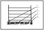
图2为基于概率密度聚类结果示意图;Fig. 2 is a schematic diagram of clustering results based on probability density;
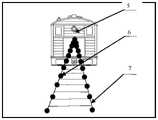
图3为左右轨道直线点遍历示意图;Figure 3 is a schematic diagram of the traversal of the left and right track straight line points;
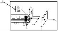
图4为毫米波雷达和相机联合标定示意图;Figure 4 is a schematic diagram of the joint calibration of the millimeter-wave radar and the camera;
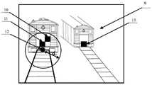
图5为毫米波雷达和视觉空间距离信息融合的雷达点筛选示意图。Figure 5 is a schematic diagram of radar point screening for millimeter-wave radar and visual-spatial distance information fusion.
具体实施方式Detailed ways
下面结合附图和实施例对本发明做进一步的详细说明。The present invention will be further described in detail below with reference to the accompanying drawings and embodiments.
如附图所示,本发明的一种时-空同步的毫米波雷达和视觉信息融合方法,包括以下步骤:As shown in the accompanying drawings, a spatio-temporal synchronization millimeter-wave radar and visual information fusion method of the present invention includes the following steps:
步骤一、利用毫米波雷达传感器的报文数据解析完成被测目标初定位,具体步骤为:
首先将毫米波雷达传感器安装在行驶列车车头位置,以毫米波雷达最大平面的几何中心为坐标原点,以行驶列车前进方向为Yrw轴,竖直向上方向为Zrw轴,行驶列车正右侧方向为Xrw轴,建立毫米波雷达三维直角坐标系。毫米波雷达传感器在毫米波雷达三维直角坐标系中的俯仰角、偏航角和滚转角均为零,如图4中8所示。毫米波雷达传感器通过CAN总线与计算机进行连接,毫米波雷达传感器用于获取对前方所有目标列车检测得到的报文数据信息。然后利用计算机MFC功能及毫米波雷达通讯协议完成雷达报文数据解析(具体参见王升亮.ARS408_ARS404_SRR308通讯协议[M].Technical_Documentation,2019.10.01),所述的前方所有目标列车包含前方同轨列车(同轨静止列车或与行驶列车相向而行的同轨列车)和前方相邻轨道列车(静止列车或与行驶列车相向而行的相邻轨道列车)。所述的报文数据信息包括前方所有目标与毫米波雷达坐标原点的横向距离dx和纵向距离dy;First, install the millimeter-wave radar sensor at the head of the traveling train, take the geometric center of the largest plane of the millimeter-wave radar as the coordinate origin, take the forward direction of the traveling train as the Yrw axis, the vertical upward direction as the Zrw axis, and the right side of the traveling train The direction is the Xrw axis, and the three-dimensional Cartesian coordinate system of the millimeter-wave radar is established. The pitch angle, yaw angle and roll angle of the millimeter-wave radar sensor in the three-dimensional rectangular coordinate system of the millimeter-wave radar are all zero, as shown in 8 in Figure 4. The millimeter-wave radar sensor is connected to the computer through the CAN bus, and the millimeter-wave radar sensor is used to obtain the message data information obtained by detecting all the target trains ahead. Then use the computer MFC function and the millimeter wave radar communication protocol to complete the data analysis of the radar message (for details, see Wang Shengliang.ARS408_ARS404_SRR308 communication protocol [M].Technical_Documentation, 2019.10.01). A stationary train or a train on the same track running opposite a moving train) and a train on the adjacent track in front (a stationary train or an adjacent track train running opposite to the moving train). The message data information includes the horizontal distance dx and the vertical distancedy between all the targets ahead and the origin of the millimeter-wave radar coordinates;
步骤二、利用相机基于图像处理技术完成行驶列车行进轨道检测和前方同轨列车位置检测,具体包括以下步骤:Step 2: Using the camera to complete the detection of the running track of the traveling train and the position detection of the train ahead on the same track based on the image processing technology, which specifically includes the following steps:
第一步,将相机安装于毫米波雷达传感器正下方的行驶列车车头上,通常为5cm,以相机的光心为坐标原点建立相机三维直角坐标系Xcw-Ycw-Zcw,相机三维直角坐标系各个坐标轴与毫米波雷达三维直角坐标系中各个坐标轴平行且Zrw轴与Zcw轴重合。在相机三维直角坐标系下相机的俯仰角、偏航角和滚转角均为零,如图4中8所示。相机与毫米波雷达之间以及相机与计算机之间分别通过USB数据线连接。利用相机对行驶列车前方的场景进行实时图像采集,采集的前方场景图像中包含前方所有目标列车以及行驶列车行进轨道。建立图像坐标系Xp-Yp,如图4中9所示,坐标原点位于相机光轴与图像平面交点,Xp,Yp分别沿前方场景图像长度方向和宽度方向。The first step is to install the camera on the head of the moving train directly below the millimeter-wave radar sensor, usually 5cm, and use the optical center of the camera as the coordinate origin to establish the camera's three-dimensional rectangular coordinate system Xcw -Ycw -Zcw , the camera three-dimensional right angle Each coordinate axis of the coordinate system is parallel to each coordinate axis in the three-dimensional rectangular coordinate system of the millimeter wave radar, and the Zrw axis coincides with the Zcw axis. In the camera's three-dimensional Cartesian coordinate system, the pitch, yaw and roll angles of the camera are all zero, as shown in Figure 4. The camera and the millimeter-wave radar and the camera and the computer are respectively connected by USB data cables. The camera is used to collect real-time images of the scene in front of the moving train, and the collected front scene image includes all the target trains ahead and the running track of the moving train. An image coordinate systemXp -Yp is established, as shown in 9 in Figure 4, the coordinate origin is located at the intersection of the camera's optical axis and the image plane, andXp andYp are respectively along the length and width directions of the front scene image.
第二步,对第一步中相机采集的前方场景图像基于累计概率霍夫变换(具体参见邱东,翁蒙,杨宏韬.基于改进概率霍夫变换的车道线快速检测方法.计算机技术与发展[J].2020,30(05))完成行驶列车行进轨道直线检测及基于直线斜率完成行驶列车行进轨道直线初步筛选。In the second step, the forward scene image collected by the camera in the first step is based on the cumulative probability Hough transform (for details, please refer to Qiu Dong, Weng Meng, Yang Hongtao. Fast lane detection method based on improved probability Hough transform. Computer Technology and Development [ J]. 2020, 30(05)) Completed the detection of the straight line of the running track of the running train and completed the preliminary screening of the straight line of the running track of the running train based on the slope of the straight line.
所述的行驶列车行进轨道直线初步筛选方法的具体过程为:依据行驶列车行进轨道在前方场景图像中的位置信息(包括斜率和起始点位置)以及相机的安装位置,选定行驶列车行进轨道斜率的阈值,阈值的选取原则包括必须将行进轨道的左右两侧轨道的斜率均包含在内,同时尽可能地去除横向直线等不必要的直线,最终获得包含左右两侧轨道在内的以点斜式表示的多条直线信息,完成基于累计概率霍夫变换的行驶列车行进轨道直线初步筛选。The specific process of the method for preliminary screening of straight lines of the traveling trains is as follows: according to the position information (including the slope and the starting point position) of the traveling tracks of the traveling trains in the front scene image and the installation position of the camera, the slope of the traveling tracks of the traveling trains is selected. The selection principle of the threshold includes that the slopes of the left and right tracks of the traveling track must be included, and at the same time, unnecessary straight lines such as horizontal straight lines must be removed as much as possible, and finally a point slope including the left and right tracks is obtained. The multiple straight line information represented by the formula is used to complete the preliminary screening of the traveling train track straight lines based on the cumulative probability Hough transform.
第三步,对第二步所得包含左右两侧轨道在内的多条直线信息进行基于DBSCAN概率密度聚类的轨道直线筛选和基于队列的轨道直线修正,得到修正后的两侧轨道直线位置信息,左右两侧轨道直线分别以lleft,lright表示,斜率分别为kleft,kright,取左右两侧轨道直线lleft,lright交点,以p0表示,具体实现方式如下:The third step is to perform the straight line screening based on the DBSCAN probability density clustering and the straight line correction based on the queue on the multiple straight line information including the left and right tracks obtained in the second step, and obtain the corrected straight line position information of the two sides of the track. , the left and right track straight lines are represented by lleft and lright respectively, and the slopes are kleft and kright respectively. Take the intersection of the left and right track straight lines lleft and lright , which is represented by p0. The specific implementation is as follows:
步骤101,选取经过行驶列车行进轨道直线初步筛选得到的多条直线,基于DBSCAN概率密度聚类算法(具体参见Abdellah IDRISSI,Altaf ALAOUI.A Multi-CriteriaDecision Method in the DBSCAN Algorithm for Better Clustering[J].International Journal of Advanced Computer Science and Applications,2016.(基于多准则决策方法的DBSCAN聚类算法))对行进轨道的左右两侧轨道进行精确识别,得到以点斜式表示的两侧轨道的初步直线位置信息,斜率为kj,其中j代表基于BSCAN聚类算法初步获得的直线数量,j=1,2,..n(n<5);同时由于检测过程是实时性的,对于检测过程中出现的部分周期内两侧轨道直线位置信息偏离现象,因此执行步骤102;Step 101, select a plurality of straight lines obtained through preliminary screening of the traveling train traveling track straight line, based on the DBSCAN probability density clustering algorithm (refer to Abdellah IDRISSI, Altaf ALAOUI.A Multi-CriteriaDecision Method in the DBSCAN Algorithm for Better Clustering [J]. International Journal of Advanced Computer Science and Applications, 2016. (DBSCAN Clustering Algorithm Based on Multi-criteria Decision-Making Method)) Accurately identify the left and right orbits of the traveling orbit, and obtain the preliminary linear positions of the orbits on both sides expressed in a point-slope format information, the slope is kj , where j represents the number of straight lines initially obtained based on the BSCAN clustering algorithm, j=1,2,..n(n<5); at the same time, since the detection process is real-time, The deviation phenomenon of the linear position information of the tracks on both sides within the partial period of , so step 102 is performed;
步骤102,将每一侧轨道的初步直线位置信息分别设置一个经验长度Length=5的队列,以保证每次DBSCAN聚类算法所得直线全部进入队列;Step 102, the preliminary straight line position information of each side track is set to a queue with an empirical length of Length=5 respectively, to ensure that the straight lines obtained by the DBSCAN clustering algorithm all enter the queue;
步骤103,依次将利用DBSCAN概率密度聚类算法计算得到的两侧轨道初步直线位置信息的直线斜率kj进入队列,选取队列的平均值kmean作为比较值

第四步,选取第三步所得修正后的两侧轨道直线位置信息,使用基于对数的轨道直线遍历方式,实现沿轨道方向前方同轨列车附近点的高密度遍历以及远离同轨列车位置的低密度遍历得到左右两侧轨道直线的遍历点在前方场景图像中的点坐标pleft(xleft,yleft),pright(xright,yright),具体实现方式如下:The fourth step is to select the corrected linear position information of the two sides of the track obtained in the third step, and use the logarithm-based linear track traversal method to achieve high-density traversal of points near the same-track trains in front of the track direction and distances away from the same-track trains. The low-density traversal obtains the point coordinates pleft (xleft , yleft ) and pright (xright , yright ) of the traversal points of the left and right track straight lines in the front scene image. The specific implementation is as follows:
步骤101,取两侧轨道直线lleft,lright的交点p0为初始遍历点;Step 101, take the intersection point p0 of the orbital lines lleft and lright on both sides as the initial traversal point;
步骤102,沿图4中Yp轴方向在前方场景图像中分别对两侧轨道直线进行遍历,两侧轨道取相同遍历距离为

步骤103,获取左右两侧轨道直线遍历点Yp轴方向坐标,步骤为:Step 103: Obtain the coordinates of the Y andp -axis directions of the track straight line traversal points on the left and right sides, and the steps are:

式(1)中:yleft,yright分别为左右两侧轨道直线遍历点在Yp轴方向坐标,

步骤104,依据步骤101-103得到左右两侧轨道遍历点的Xp轴方向坐标,最终得到左右两侧轨道基于对数的全部的遍历点在前方场景图像中的点坐标pleft(xleft,yleft),pright(xright,yright),实现结果如图3所示,图3中6和7分别表示遍历后的左右轨道直线的遍历点信息。In step 104, according to steps 101-103, the Xp -axis direction coordinates of the track traversal points on the left and right sides are obtained, and finally the point coordinates pleft (xleft , yleft ), pright (xright , yright ), the implementation result is shown in Figure 3, where 6 and 7 in Figure 3 respectively represent the traversal point information of the left and right track straight lines after traversal.

式(2)中:xleft,xright分别为左右两侧轨道遍历点的Xp轴方向坐标,yleft,yright分别为左右两侧轨道遍历点Yp轴方向坐标,

第五步,选取第四步所得左右两侧轨道遍历点在前方场景图像中的点坐标pleft(xleft,yleft),pright(xright,yright),基于左右两侧轨道直线的遍历点灰度值梯度变化完成对于前方同轨列车的识别。由于轨道的灰度值较高,而前方同轨列车底部的灰度值较低,因此在左右轨道遍历点中存在灰度值突变的位置,将其确定为前方同轨列车位置。具体的实现方式如下:The fifth step is to select the point coordinates pleft (xleft , yleft ) and pright (xright , yright ) of the left and right track traversal points obtained in the fourth step in the front scene image, based on the straight lines of the left and right tracks. The gradient change of the gray value of the traversing point completes the identification of the train in front of the same track. Since the gray value of the track is high, and the gray value of the bottom of the train on the same track in front is low, there is a sudden change of gray value in the left and right track traversal points, which is determined as the position of the train on the same track ahead. The specific implementation is as follows:
步骤101,对轨道直线的遍历点灰度值进行均匀化操作。为了消除遍历点灰度值的跳动问题,计算连续4个遍历点的灰度值的均值作为一个新的均值遍历点,坐标值为pmean_left(xmean_left,ymean_left),pmean_right(xmean_right,ymean_right);Step 101 , perform a homogenization operation on the gray value of the traversing point of the track straight line. In order to eliminate the jumping problem of the gray value of the traversal point, calculate the mean value of the gray value of four consecutive traversal points as a new mean traversal point, and the coordinate values are pmean_left (xmean_left , ymean_left ), pmean_right (xmean_right , ymean_right );
步骤102,确定灰度值突变位置。将坐标pmean_left(xmean_left,ymean_left),pmean_right(xmean_right,ymean_right)作为前方同轨列车底部左右位置点坐标,之后选取前方同轨列车底部左右位置点坐标pmean_left(xmean_left,ymean_left),pmean_right(xmean_right,ymean_right)的算数平均值作为所求的前方同轨列车底部中间位置点的坐标:Step 102: Determine the position of sudden change of gray value. Take the coordinates pmean_left (xmean_left , ymean_left ) and pmean_right (xmean_right , ymean_right ) as the coordinates of the left and right position points at the bottom of the same-track train ahead, and then select the coordinates pmean_left (xmean_left ,ymean_left ), the arithmetic mean of pmean_right (xmean_right , ymean_right ) is used as the coordinates of the middle position of the bottom of the same-track train ahead:

式(3)中:xbottom,ybottom为前方同轨列车底部中间位置点沿Xp轴,Yp轴方向坐标,xmean-left,ymean-left为前方同轨列车底部左侧位置点沿Xp轴,Yp轴方向坐标,xmean-right,ymean-right为前方同轨列车底部右侧位置点沿Xp轴,Yp轴方向坐标,最终得到前方同轨列车底部位置点坐标p(xbottom,ybottom),如图5中黑色圆点12所示;In formula (3): xbottom , ybottom are the coordinates of the middle position of the bottom of the co-track train ahead along the Xp -axis and Yp -axis, xmean-left , ymean-left are the left position of the bottom of the co-track train ahead Coordinates along the Xp -axis and Yp -axis, xmean-right , ymean-right are the coordinates of the right position point at the bottom of the front co-track train along the Xp -axis, Yp -axis, and finally get the bottom position point of the front co-track train Coordinate p(xbottom , ybottom ), as shown by the
第六步,选取坐标为p(xbottom,ybottom)的前方同轨列车底部中间位置点,基于卡尔曼滤波进行位置修正,得到每一周期内平滑过渡的前方同轨列车底部中间位置点信息,具体实现方式如下:The sixth step, select the middle position point at the bottom of the front co-track train whose coordinates are p(xbottom , ybottom ), perform position correction based on Kalman filter, and obtain the information of the middle position point at the bottom of the front co-track train that smoothly transitions in each cycle , the specific implementation is as follows:
对于前方同轨列车位置点偏离现象和部分周期未检测到前方同轨列车现象,首先设定卡尔曼滤波距离经验阈值dthreshold=50(具体参见Alessio Gagliardi,Francesco deGioia,Sergio Saponara.A real-time video smoke detection algorithm based onKalman filter and CNN[J].Journal of Real-Time Image Processing,2021.一种基于卡尔曼滤波和CNN的实时视频检测算法),当第i周期前方同轨列车底部中间位置点p(xbottom,ybottom)i和第i-1周期前方同轨列车底部中间位置点p(xbottom,ybottom)i-1间欧氏距离大于距离阈值dthreshold,则舍弃本周期前方同轨列车底部中间目标位置点,采用上一周期前方同轨列车底部中间目标位置点代替。同时,对于所有小于距离阈值的前方同轨列车底部中间目标位置点进行卡尔曼滤波处理,实现点位置的平滑过渡;For the position point deviation of the preceding co-track train and the phenomenon that the preceding co-track train is not detected in some cycles, first set the Kalman filter distance empirical threshold dthreshold =50 (see Alessio Gagliardi, Francesco deGioia, Sergio Saponara.A real-time for details). video smoke detection algorithm based on Kalman filter and CNN[J].Journal of Real-Time Image Processing, 2021. A real-time video detection algorithm based on Kalman filter and CNN), when the middle position of the bottom of the same-track train ahead of the i-th cycle The Euclidean distance between p(xbottom ,ybottom )i and the middle position of the bottom of the same-track train in front of the i-1th cycle p(xbottom ,ybottom )i-1 is greater than the distance threshold dthreshold , then discard the same track in front of this cycle. The middle target position point at the bottom of the rail train is replaced by the middle target position point at the bottom of the previous same-track train in the previous cycle. At the same time, Kalman filter processing is performed for all the target position points at the bottom of the front same-track trains that are less than the distance threshold to achieve a smooth transition of point positions;
步骤三,基于时-空同步的联合标定方法融合毫米波雷达信息和视觉信息,完成前方同轨列车的准确识别与测距,具体包括以下步骤:Step 3: The joint calibration method based on time-space synchronization integrates millimeter-wave radar information and visual information to complete the accurate identification and ranging of the same-track train ahead, which specifically includes the following steps:
第一步,毫米波雷达和相机多线程同步;The first step is multi-thread synchronization of millimeter-wave radar and camera;
在进行数据采集时,为使毫米波雷达和相机能采集到同一时刻的目标数据,选取毫米波雷达数据接收线程、相机接收线程和计算机数据处理线程三线程融合方式实现基于毫米波雷达和视觉信息的多线程时间同步(具体参见骆斌,费翔林.多线程技术的研究与应用[J].计算机研究与发展,2000,(04));During data collection, in order to enable the millimeter-wave radar and the camera to collect the target data at the same time, the three-thread fusion method of the millimeter-wave radar data receiving thread, the camera receiving thread and the computer data processing thread is selected to realize the millimeter-wave radar and visual information based on the three-thread fusion method. Multi-thread time synchronization (for details, see Luo Bin, Fei Xianglin. Research and Application of Multi-thread Technology [J]. Computer Research and Development, 2000, (04));
第二步,利用毫米波雷达坐标系、相机坐标系以及图像坐标系之间的平移和旋转关系得到毫米波雷达坐标系中任意一雷达点转换到图像坐标系中的位置,其转换关系式如下(具体参见罗逍,姚远,张金换.一种毫米波雷达和摄像头联合标定方法[N].清华大学学报:2014年第54卷第3期),The second step is to use the translation and rotation relationship between the millimeter-wave radar coordinate system, the camera coordinate system and the image coordinate system to obtain the position of any radar point in the millimeter-wave radar coordinate system converted to the image coordinate system. The conversion relationship is as follows (For details, see Luo Xiao, Yao Yuan, Zhang Jinhuan. A joint calibration method of millimeter-wave radar and camera [N]. Journal of Tsinghua University: 2014, Vol. 54, No. 3),

式(4)中,xp,yp为毫米波雷达中的点在图像坐标系下的Xp轴方向和Yp轴方向坐标,xrw,yrw为毫米波雷达中的点在毫米波雷达坐标系下的Xrw轴方向和Yrw轴方向坐标,Cx为相机光轴沿Xrw轴方向偏移量,Cy为相机光轴沿Yp轴方向的偏移量,fx为沿Xp轴方向相机焦距,fy为沿Yp轴方向相机焦距,Lx为雷达投影坐标系和摄像头投影坐标系X轴之间的间距,Ly为雷达投影坐标系和摄像头投影坐标系Y轴之间的间距,H为相机安装高度。In formula (4), xp , yp are the coordinates of the Xp -axis and Yp -axis directions of the point in the millimeter-wave radar in the image coordinate system, and xrw , yrw are the point in the millimeter-wave radar in the millimeter-wave The coordinates of the Xrw axis and Yrw axis in the radar coordinate system, Cx is the offset of the camera optical axis along the Xrw axis, Cy is the offset of the camera optical axis along the Yp axis, and fx is The focal length of the camera along the Xp -axis, fy is the focal length of the camera along the Yp -axis, Lx is the distance between the radar projection coordinate system and the X-axis of the camera projection coordinate system, and Ly is the radar projection coordinate system and the camera projection coordinate system The distance between the Y axes, H is the camera installation height.
最后利用公式(4),将步骤二中第六步所得前方同轨列车底部中间位置点p(xbottom,ybottom)的图像位置信息转换为毫米波雷达坐标系下的坐标,然后计算得到同轨列车底部中间位置点p(xbottom,ybottom)在毫米波雷达坐标系下的相对距离dw。Finally, using formula (4), the image position information of the bottom middle position point p(xbottom , ybottom ) of the front same-track train obtained in the sixth step in
具体转换步骤为:首先获取同轨列车底部中间位置点坐标p(xbottom,ybottom)在Xp轴方向位置xbottom和Yp轴方向位置ybottom,之后将xbottom,ybottom转换到毫米波雷达坐标系下的坐标xw,yw,通过公式
第三步,首先将步骤一中雷达获得的所有目标的横向距离dx和纵向距离dy利用式(4)转换到相机的图像坐标系Xp-Yp下,以雷达点坐标pi(xp,yp)的形式在前方场景图像中显示,如图5中黑色方块10,11,13所示。然后将步骤一中前方所有目标与毫米波雷达坐标原点的横向距离dx和纵向距离dy转化为毫米波雷达坐标系下的相对距离
步骤101,对于雷达检测过程中的二次反射导致同一目标出现多组距离成倍数的雷达点数据现象,如图5中10和11所示,其中10的实际相对距离远大于11,首先将前方所有目标与毫米波雷达坐标原点的横向距离dx和纵向距离dy转化为毫米波雷达坐标系下的相对距离
步骤102,对于雷达检测过程中出现检测到相邻车辆的雷达点信息现象,如图5中13所示,选取粗筛选所得雷达点坐标pj(xp,yp),在前方场景图像中,根据雷达点坐标pj(xp,yp)位置信息,以步骤二获得的前方场景图像中同轨列车底部中间位置点信息p(xbottom,ybottom)作为参考中心,依据欧式距离最小约束原则,选取与前方同轨列车底部中间位置点p(xbottom,ybottom)最近的雷达点坐标pj(xp,yp)作为最终的雷达点筛选结果,与最终筛选的雷达点对应的相对距离信息dr作为最终的测距结果。Step 102 , for the phenomenon of radar point information that detects adjacent vehicles during the radar detection process, as shown in 13 in FIG. 5 , select the radar point coordinates pj (xp , yp ) obtained by rough screening, in the front scene image. , according to the position information of the radar point coordinates pj (xp , yp ), take the middle position information p (xbottom , ybottom ) of the bottom middle position of the same-track train in the front scene image obtained in

式(5)中:xpi,ypi为雷达点在图像坐标系中的横纵坐标,xbottom,ybottom,为前方同轨列车底部中间位置点的横纵坐标。前方同轨列车底部中间位置点为图5中12所示,选取与其最近的雷达点作为最终雷达点检测结果,实现对于相邻车辆雷达点13的筛除,得到最终基于视觉匹配雷达点11,选取此时雷达点距离信息作为最终雷达点筛选结果,选取该雷达点对应相对距离信息dr作为最终的测距结果。In formula (5): xpi , ypi are the abscissa and ordinate coordinates of the radar point in the image coordinate system, and xbottom , ybottom , are the abscissa and ordinate of the middle position of the bottom of the same-track train ahead. The middle position of the bottom of the same-track train in front is shown as 12 in Figure 5, and the nearest radar point is selected as the final radar point detection result to screen out the adjacent vehicle radar points 13, and finally obtain the
Claims (5)


Priority Applications (1)
| Application Number | Priority Date | Filing Date | Title |
|---|---|---|---|
| CN202110455091.8ACN113189583B (en) | 2021-04-26 | 2021-04-26 | Time-space synchronization millimeter wave radar and visual information fusion method |
Applications Claiming Priority (1)
| Application Number | Priority Date | Filing Date | Title |
|---|---|---|---|
| CN202110455091.8ACN113189583B (en) | 2021-04-26 | 2021-04-26 | Time-space synchronization millimeter wave radar and visual information fusion method |
Publications (2)
| Publication Number | Publication Date |
|---|---|
| CN113189583A CN113189583A (en) | 2021-07-30 |
| CN113189583Btrue CN113189583B (en) | 2022-07-01 |
Family
ID=76978999
Family Applications (1)
| Application Number | Title | Priority Date | Filing Date |
|---|---|---|---|
| CN202110455091.8AActiveCN113189583B (en) | 2021-04-26 | 2021-04-26 | Time-space synchronization millimeter wave radar and visual information fusion method |
Country Status (1)
| Country | Link |
|---|---|
| CN (1) | CN113189583B (en) |
Families Citing this family (4)
| Publication number | Priority date | Publication date | Assignee | Title |
|---|---|---|---|---|
| CN113900087A (en)* | 2021-08-31 | 2022-01-07 | 通号城市轨道交通技术有限公司 | Train data measuring method and device, electronic equipment and storage medium |
| CN114708585B (en)* | 2022-04-15 | 2023-10-10 | 电子科技大学 | A three-dimensional target detection method based on the fusion of millimeter wave radar and vision based on the attention mechanism |
| CN115169452B (en)* | 2022-06-30 | 2023-04-28 | 北京中盛国芯科技有限公司 | Target information system and method based on space-time synchronous queue characteristic radar fusion |
| CN115877328B (en)* | 2023-03-06 | 2023-05-12 | 成都鹰谷米特科技有限公司 | Signal receiving and transmitting method of array radar and array radar |
Citations (7)
| Publication number | Priority date | Publication date | Assignee | Title |
|---|---|---|---|---|
| CN107818557A (en)* | 2016-09-12 | 2018-03-20 | 德尔福技术有限公司 | Enhanced camera object for automotive vehicle detects |
| CN108960183A (en)* | 2018-07-19 | 2018-12-07 | 北京航空航天大学 | A kind of bend target identification system and method based on Multi-sensor Fusion |
| WO2020134512A1 (en)* | 2018-12-29 | 2020-07-02 | 南京慧尔视智能科技有限公司 | Traffic detection system based on millimeter wave radar and video |
| CN111368706A (en)* | 2020-03-02 | 2020-07-03 | 南京航空航天大学 | Data fusion dynamic vehicle detection method based on millimeter wave radar and machine vision |
| CN111461088A (en)* | 2020-06-17 | 2020-07-28 | 长沙超创电子科技有限公司 | Rail transit obstacle avoidance system based on image processing and target recognition |
| CN111546328A (en)* | 2020-04-02 | 2020-08-18 | 天津大学 | Hand-eye calibration method based on three-dimensional vision measurement |
| CN111856441A (en)* | 2020-06-09 | 2020-10-30 | 北京航空航天大学 | A train positioning method based on fusion of vision and millimeter wave radar |
Family Cites Families (5)
| Publication number | Priority date | Publication date | Assignee | Title |
|---|---|---|---|---|
| US9052393B2 (en)* | 2013-01-18 | 2015-06-09 | Caterpillar Inc. | Object recognition system having radar and camera input |
| CN107609522B (en)* | 2017-09-19 | 2021-04-13 | 东华大学 | An information fusion vehicle detection system based on lidar and machine vision |
| US11287523B2 (en)* | 2018-12-03 | 2022-03-29 | CMMB Vision USA Inc. | Method and apparatus for enhanced camera and radar sensor fusion |
| CN110208793B (en)* | 2019-04-26 | 2022-03-11 | 纵目科技(上海)股份有限公司 | Auxiliary driving system, method, terminal and medium based on millimeter wave radar |
| CN111832410B (en)* | 2020-06-09 | 2022-09-20 | 北京航空航天大学 | Forward train detection method based on fusion of vision and laser radar |
- 2021
- 2021-04-26CNCN202110455091.8Apatent/CN113189583B/enactiveActive
Patent Citations (7)
| Publication number | Priority date | Publication date | Assignee | Title |
|---|---|---|---|---|
| CN107818557A (en)* | 2016-09-12 | 2018-03-20 | 德尔福技术有限公司 | Enhanced camera object for automotive vehicle detects |
| CN108960183A (en)* | 2018-07-19 | 2018-12-07 | 北京航空航天大学 | A kind of bend target identification system and method based on Multi-sensor Fusion |
| WO2020134512A1 (en)* | 2018-12-29 | 2020-07-02 | 南京慧尔视智能科技有限公司 | Traffic detection system based on millimeter wave radar and video |
| CN111368706A (en)* | 2020-03-02 | 2020-07-03 | 南京航空航天大学 | Data fusion dynamic vehicle detection method based on millimeter wave radar and machine vision |
| CN111546328A (en)* | 2020-04-02 | 2020-08-18 | 天津大学 | Hand-eye calibration method based on three-dimensional vision measurement |
| CN111856441A (en)* | 2020-06-09 | 2020-10-30 | 北京航空航天大学 | A train positioning method based on fusion of vision and millimeter wave radar |
| CN111461088A (en)* | 2020-06-17 | 2020-07-28 | 长沙超创电子科技有限公司 | Rail transit obstacle avoidance system based on image processing and target recognition |
Non-Patent Citations (4)
| Title |
|---|
| 《A Train Positioning Method Based-On Vision and Millimeter-Wave Radar Data Fusion》;Z. Wang, G. Yu, B. Zhou, P. Wang and X. Wu;《 IEEE Transactions on Intelligent Transportation Systems》;20210203;1 - 11* |
| 丁雅斌 ; 彭翔 ; 刘则毅 ; 牛憨笨.《基于广义等值面提取的多视场深度像融合》.《工程图学学报》.2004,* |
| 姚文韬 ; 沈春锋 ; 董文生.《一种自适应摄像机与激光雷达联合标定算法》.《控制工程》.2017,* |
| 郑云水 ; 郭双全 ; 董昱.《基于雷达测量数据的列车运行前方障碍物检测方法研究》.《铁道学报》.2021,* |
Also Published As
| Publication number | Publication date |
|---|---|
| CN113189583A (en) | 2021-07-30 |
Similar Documents
| Publication | Publication Date | Title |
|---|---|---|
| CN113189583B (en) | Time-space synchronization millimeter wave radar and visual information fusion method | |
| CN109684921B (en) | A Road Boundary Detection and Tracking Method Based on 3D LiDAR | |
| Zhangyu et al. | A camera and LiDAR data fusion method for railway object detection | |
| CN104021676B (en) | Vehicle location based on vehicle dynamic video features and vehicle speed measurement method | |
| CN111461088B (en) | Rail transit obstacle avoidance system based on image processing and target recognition | |
| CN112991391A (en) | Vehicle detection and tracking method based on radar signal and vision fusion | |
| Perrollaz et al. | Long range obstacle detection using laser scanner and stereovision | |
| CN112698302A (en) | Sensor fusion target detection method under bumpy road condition | |
| CN115113206B (en) | Pedestrian and obstacle detection method for assisting driving of underground rail car | |
| CN112991369A (en) | Method for detecting overall dimension of running vehicle based on binocular vision | |
| WO2021253245A1 (en) | Method and device for identifying vehicle lane changing tendency | |
| CN115856872B (en) | Vehicle motion trail continuous tracking method | |
| Wang et al. | Object tracking based on the fusion of roadside LiDAR and camera data | |
| CN113850102A (en) | Vehicle-mounted visual detection method and system based on millimeter-wave radar assistance | |
| CN114357019A (en) | Method for monitoring data quality of road side sensing unit in intelligent networking environment | |
| CN105913454A (en) | Pixel coordinate locus prediction method of motion object in video image | |
| WO2025050329A1 (en) | Multi-roadside laser radar sensor point cloud data temporal-spatial registration method | |
| CN110443819A (en) | A kind of track detection method and device of monorail train | |
| Murmu et al. | Relative velocity measurement using low cost single camera-based stereo vision system | |
| Li et al. | Multi-sensor fusion for robust localization with moving object segmentation in complex dynamic 3D scenes | |
| CN115980754A (en) | Vehicle detection and tracking method fusing sensor information | |
| CN117974773A (en) | Method for calibrating bow direction based on geographic azimuth under ship static condition in ship lock | |
| CN117671972A (en) | Vehicle speed detection method and device for slow traffic system | |
| Huang et al. | FRVO-Mono: Feature-based railway visual odometry with monocular camera | |
| CN115601388A (en) | Image multi-target vehicle tracking and track checking method carrying following model |
Legal Events
| Date | Code | Title | Description |
|---|---|---|---|
| PB01 | Publication | ||
| PB01 | Publication | ||
| SE01 | Entry into force of request for substantive examination | ||
| SE01 | Entry into force of request for substantive examination | ||
| GR01 | Patent grant | ||
| GR01 | Patent grant |