CN113180842B - A medical device containing device - Google Patents
A medical device containing deviceDownload PDFInfo
- Publication number
- CN113180842B CN113180842BCN202110539847.7ACN202110539847ACN113180842BCN 113180842 BCN113180842 BCN 113180842BCN 202110539847 ACN202110539847 ACN 202110539847ACN 113180842 BCN113180842 BCN 113180842B
- Authority
- CN
- China
- Prior art keywords
- box body
- branch pipe
- sealing
- worm wheel
- air inlet
- Prior art date
- Legal status (The legal status is an assumption and is not a legal conclusion. Google has not performed a legal analysis and makes no representation as to the accuracy of the status listed.)
- Active
Links
Images


Classifications
- A—HUMAN NECESSITIES
- A61—MEDICAL OR VETERINARY SCIENCE; HYGIENE
- A61B—DIAGNOSIS; SURGERY; IDENTIFICATION
- A61B50/00—Containers, covers, furniture or holders specially adapted for surgical or diagnostic appliances or instruments, e.g. sterile covers
- A61B50/30—Containers specially adapted for packaging, protecting, dispensing, collecting or disposing of surgical or diagnostic appliances or instruments
- A—HUMAN NECESSITIES
- A61—MEDICAL OR VETERINARY SCIENCE; HYGIENE
- A61B—DIAGNOSIS; SURGERY; IDENTIFICATION
- A61B50/00—Containers, covers, furniture or holders specially adapted for surgical or diagnostic appliances or instruments, e.g. sterile covers
- A61B2050/005—Containers, covers, furniture or holders specially adapted for surgical or diagnostic appliances or instruments, e.g. sterile covers with a lid or cover
- A—HUMAN NECESSITIES
- A61—MEDICAL OR VETERINARY SCIENCE; HYGIENE
- A61B—DIAGNOSIS; SURGERY; IDENTIFICATION
- A61B50/00—Containers, covers, furniture or holders specially adapted for surgical or diagnostic appliances or instruments, e.g. sterile covers
- A61B50/30—Containers specially adapted for packaging, protecting, dispensing, collecting or disposing of surgical or diagnostic appliances or instruments
- A61B2050/3004—Containers specially adapted for packaging, protecting, dispensing, collecting or disposing of surgical or diagnostic appliances or instruments containing desiccant means, e.g. desiccant pouches
Landscapes
- Health & Medical Sciences (AREA)
- Life Sciences & Earth Sciences (AREA)
- Surgery (AREA)
- Heart & Thoracic Surgery (AREA)
- Engineering & Computer Science (AREA)
- Biomedical Technology (AREA)
- Nuclear Medicine, Radiotherapy & Molecular Imaging (AREA)
- Medical Informatics (AREA)
- Molecular Biology (AREA)
- Animal Behavior & Ethology (AREA)
- General Health & Medical Sciences (AREA)
- Public Health (AREA)
- Veterinary Medicine (AREA)
- Accommodation For Nursing Or Treatment Tables (AREA)
Abstract
Translated fromChinese
Description
Translated fromChinese技术领域technical field
本发明涉及医疗器械技术领域,具体是一种医疗器械盛放装置。The invention relates to the technical field of medical devices, in particular to a medical device containing device.
背景技术Background technique
医疗器械是指直接或者间接用于人体的仪器或器具,对于器具,在使用前则需要对其进行清洗消毒以及干燥,以免表面的细菌对人体的感染;对于仪器则要对其进行防护,防止空气中的水分对其造成的影响。Medical devices refer to instruments or instruments that are directly or indirectly used in the human body. For instruments, they need to be cleaned, disinfected and dried before use to prevent the bacteria on the surface from infecting the human body; for instruments, they must be protected to prevent The effect of moisture in the air on it.
医疗器械在存放的时候的需要保证存放装置内部的干燥程度,以防止空气中的水分对医疗器械产生的侵蚀现象,因此需要对盛放装置进行通风处理,目前对盛放装置进行通风的方法通常是在盛放装置的表面开设有若干通风口,空气通过通风口产生空气流动,从而带走医疗器械表面的水分,进而保证医疗器械表面的干燥性。When storing medical devices, it is necessary to ensure the dryness of the interior of the storage device to prevent the corrosion of medical devices caused by moisture in the air. Therefore, it is necessary to ventilate the storage device. The current method of ventilating the storage device is usually A number of vents are opened on the surface of the holding device, and the air flows through the vents, thereby taking away the moisture on the surface of the medical device, thereby ensuring the dryness of the surface of the medical device.
但是这种自然通风的方法不能适用在空气潮湿的环境下,在空气潮湿时,由于通风口的设置使该盛放装置不具备密封性能,导致空气中的水分通过通风口进入到盛放装置的内部,及时有一些器械盛放装置能够通过阀门控制通风口的关闭,但这种装置结构比较单一,在对箱体密封的同时可能已经进入部分湿气,而该装置则不能及时的将箱体内部的湿气排出,从而对医疗器械产生了一定的影响。However, this natural ventilation method cannot be used in a humid environment. When the air is humid, due to the setting of the ventilation port, the container does not have sealing performance, so that the moisture in the air enters the container through the ventilation port. Inside, there are some device holding devices that can control the closing of the vent through the valve, but the structure of this device is relatively simple, and some moisture may have entered the box while sealing, and the device cannot timely remove the box. The internal moisture is discharged, which has a certain impact on the medical device.
发明内容SUMMARY OF THE INVENTION
本发明的目的在于提供一种医疗器械盛放装置,以解决上述背景技术中提出的问题。The purpose of the present invention is to provide a medical device containing device to solve the above-mentioned problems in the background art.
为实现上述目的,本发明提供如下技术方案:To achieve the above object, the present invention provides the following technical solutions:
一种医疗器械盛放装置,包括箱体,所述箱体的一侧设有箱门,所述箱体远离箱门的一侧设有若干通风口,所述箱体的内部设有盛放机构,所述通风口与盛放机构之间设有密封机构、驱动机构以及排湿机构,所述箱体的内部还设有进气机构;A medical device containing device includes a box body, a box door is arranged on one side of the box body, a number of ventilation openings are arranged on the side of the box body away from the box door, and the inside of the box body is provided with a box body. A sealing mechanism, a driving mechanism and a dehumidification mechanism are arranged between the ventilation opening and the containing mechanism, and an air intake mechanism is also arranged inside the box body;
所述盛放机构用于支撑医疗器械本体;The containing mechanism is used to support the medical device body;
所述密封机构用于控制通风口的闭合;the sealing mechanism is used to control the closure of the vent;
所述排湿机构用于将箱体内部的湿气排出到箱体的外部;The moisture removal mechanism is used to discharge the moisture inside the box to the outside of the box;
所述进气机构用于控制气体间歇性进入到箱体内部;The air intake mechanism is used to control the intermittent entry of gas into the box;
所述驱动机构用于控制密封机构对通风口的闭合,其中驱动机构控制通风口闭合的同时还控制排湿机构与进气机构同时运转。The driving mechanism is used for controlling the closing of the air vent by the sealing mechanism, wherein the driving mechanism controls the closing of the air vent and also controls the simultaneous operation of the moisture removal mechanism and the air intake mechanism.
进一步的:所述密封机构包括密封板,所述密封板靠近通风口的一侧设有若干与通风口相配合的密封塞,所述密封板的另一侧与驱动机构相连接,所述密封板两侧设有限位机构,所述限位机构用于密封板的限位。Further: the sealing mechanism includes a sealing plate, one side of the sealing plate close to the ventilation opening is provided with a plurality of sealing plugs matched with the ventilation opening, the other side of the sealing plate is connected with the driving mechanism, and the sealing Limiting mechanisms are provided on both sides of the plate, and the limiting mechanisms are used to limit the position of the sealing plate.
进一步的:所述限位机构包括设置在密封板的两侧的支撑架,所述支撑架转动连接有滑轮,所述箱体内壁上设有与滑轮相互配合的滑槽,所述滑轮位于滑槽的内部并与其滚动连接。Further: the limiting mechanism includes a support frame arranged on both sides of the sealing plate, the support frame is rotatably connected with a pulley, the inner wall of the box is provided with a chute that cooperates with the pulley, and the pulley is located on the pulley. inside of the groove and rolling connection with it.
进一步的:所述排湿机构包括活塞筒,所述活塞筒的内部设有圆形活塞,所述圆形活塞与驱动机构相连接,所述圆形活塞的一侧设有第一进气支管与第一出气支管,所述圆形活塞的另一侧设有第二进气支管与第二出气支管,所述第一进气支管与第二进气支管连接有进气总管,所述第一出气支管与第二出气支管连接有出气总管。Further: the dehumidification mechanism includes a piston cylinder, the interior of the piston cylinder is provided with a circular piston, the circular piston is connected with the driving mechanism, and one side of the circular piston is provided with a first intake branch pipe With the first air outlet branch pipe, the other side of the circular piston is provided with a second air intake branch pipe and a second air outlet branch pipe, the first air intake branch pipe and the second air intake branch pipe are connected with an air intake manifold, the first An air outlet main pipe is connected with the second air outlet branch pipe.
进一步的:所述进气总管连接有分流管,所述分流管的风口朝医疗器械主体设置,所述第一进气支管、第二进气支管、第一出气支管与第二出气支管上均设有单向阀。Further: the air inlet main pipe is connected with a shunt pipe, the air outlet of the shunt pipe is arranged towards the main body of the medical device, and the first air inlet branch pipe, the second air inlet branch pipe, the first air outlet branch pipe and the second air outlet branch pipe are all on top of each other. Equipped with one-way valve.
进一步的:所述箱体的一侧设有进风口,所述进气机构包括移动板,所述移动板用于进风口的闭合,所述移动板的一侧与驱动机构相连接,所述移动板的另一侧设有弹性连接件,所述箱体的内壁上设有若干凹槽,所述弹性连接件位于凹槽的内部,所述弹性连接件用于移动板的弹性支撑。Further: one side of the box body is provided with an air inlet, the air inlet mechanism includes a moving plate, the moving plate is used for closing the air inlet, one side of the moving plate is connected with the driving mechanism, the The other side of the moving plate is provided with elastic connecting pieces, the inner wall of the box is provided with a plurality of grooves, the elastic connecting pieces are located inside the grooves, and the elastic connecting pieces are used for elastic support of the moving board.
进一步的:所述驱动机构包括电机,所述电机的输出端设有蜗杆,所述蜗杆通过传动机构与密封机构相连接,所述传动机构用于驱动机构与密封机构的连接。Further: the driving mechanism includes a motor, the output end of the motor is provided with a worm, and the worm is connected with the sealing mechanism through a transmission mechanism, and the transmission mechanism is used for the connection between the driving mechanism and the sealing mechanism.
进一步的:所述传动机构包括第一蜗轮以及不完全蜗轮,所述第一蜗轮与不完全蜗轮均与蜗杆相互啮合,所述第一蜗轮的内部设有棘齿,所述第一蜗轮的内部还设有转盘,所述转盘上设有活动支杆,所述活动支杆与棘齿相互配合,所述活动支杆与转盘弹性连接,所述转盘的侧面转动连接有第一连杆,所述第一连杆的另一端转动连接有第一滑块,所述密封板的侧面设有第一连接架,所述第一连接架贯穿第一滑块并与其滑动连接;所述不完全蜗轮的侧面连接有第二连杆,所述第二连杆的另一端转动连接有第二滑块,所述密封板的侧面设有第二连接架,所述第二连接架贯穿第二滑块并与其滑动连接。Further: the transmission mechanism includes a first worm gear and an incomplete worm gear, the first worm gear and the incomplete worm gear are meshed with the worm, the inside of the first worm gear is provided with ratchet teeth, and the inside of the first worm gear is There is also a turntable on which a movable support rod is arranged, the movable support rod cooperates with the ratchet teeth, the movable support rod is elastically connected with the turntable, and a first connecting rod is rotatably connected to the side of the turntable, so the The other end of the first connecting rod is rotatably connected with a first sliding block, the side of the sealing plate is provided with a first connecting frame, the first connecting frame penetrates the first sliding block and is slidably connected with it; the incomplete worm gear The side of the sealing plate is connected with a second connecting rod, the other end of the second connecting rod is rotatably connected with a second sliding block, the side of the sealing plate is provided with a second connecting frame, and the second connecting frame penetrates the second sliding block and slidably connected to it.
进一步的:所述蜗杆啮合有第二蜗轮,所述第二蜗轮转动连接有第三连杆,所述第三连杆转动连接有第四连杆,所述第四连杆贯穿活塞筒并与其滑动连接,所述第四连杆与圆形活塞固定连接。Further: the worm is engaged with a second worm wheel, the second worm wheel is rotatably connected with a third connecting rod, the third connecting rod is rotatably connected with a fourth connecting rod, and the fourth connecting rod penetrates the piston cylinder and is connected with it. Sliding connection, the fourth connecting rod is fixedly connected with the circular piston.
进一步的:所述蜗杆还啮合有第三蜗轮,所述第三蜗轮啮合有齿轮,所述齿轮的表面设有凸轮,所述凸轮与移动板相互配合。Further: the worm is also meshed with a third worm wheel, the third worm wheel is meshed with a gear, the surface of the gear is provided with a cam, and the cam cooperates with the moving plate.
与现有技术相比,本发明的有益效果是:一种医疗器械盛放装置,本装置在天气干燥的情况下,空气通过通风口进入到箱体的内部,从而带动医疗器械表面的水分,保证医疗器械表面的干燥性;当空气较为潮湿时,通过驱动机构带动密封机构对箱体进行密封处理,从而阻止了空气中水分进入到箱体内部,进而保证了医疗器械表面的干燥性;在对箱体密封的同时驱动机构还带动排湿机构与进气机构运转,排湿机构能够及时将箱体内部的水分排出,进一步的保证了医疗器械表面的干燥性,此外进气机构的间歇性进气在提高箱体密封性的前提下保证了箱体内外压力不会产生太大变化,避免了箱体内部压力过小对医疗器械本体造成的损伤。Compared with the prior art, the beneficial effects of the present invention are: a medical device containing device, in the case of dry weather, the air enters the inside of the box through the vent, thereby driving the moisture on the surface of the medical device, To ensure the dryness of the surface of the medical device; when the air is relatively humid, the sealing mechanism is driven by the driving mechanism to seal the box, thereby preventing the moisture in the air from entering the inside of the box, thereby ensuring the dryness of the surface of the medical device; While sealing the box, the drive mechanism also drives the moisture removal mechanism and the air intake mechanism to operate. The moisture removal mechanism can discharge the moisture inside the box in time, which further ensures the dryness of the surface of the medical device. The air intake ensures that the pressure inside and outside the box will not change too much under the premise of improving the sealing of the box body, and avoids the damage to the medical device body caused by too small internal pressure of the box body.
附图说明Description of drawings
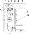
图1为一种医疗器械盛放装置整体结构正视图。FIG. 1 is a front view of the overall structure of a medical device containing device.
图2为一种医疗器械盛放装置密封板结构示意图。FIG. 2 is a schematic structural diagram of a sealing plate of a medical device containing device.
图3为一种医疗器械盛放装置第一蜗轮连接示意图。FIG. 3 is a schematic diagram of the connection of the first worm gear of a medical device containing device.
图4为一种医疗器械盛放装置不完全蜗轮连接示意图。FIG. 4 is a schematic diagram of incomplete worm gear connection of a medical device containing device.
图5为一种医疗器械盛放装置排湿机构正视图。Fig. 5 is a front view of a moisture removal mechanism of a medical device containing device.
图6为一种医疗器械盛放装置进风机构正视图。Fig. 6 is a front view of an air inlet mechanism of a medical device containing device.
图中:1-密封板、2-滑槽、3-滑轮、4-支撑架、5-蜗杆、6-箱体、7-盛放机构、8-凹槽、9-箱门、10-分流管、11-通风口、12-密封塞、13-弹性连接件、14-电机、15-第一蜗轮、16-活动支杆、17-转盘、18-第一连杆、19-第一滑块、20-第一连接架、21-不完全蜗轮、22-第二连杆、23-第二滑块、24-第二连接架、25-第二蜗轮、26-第三连杆、27-第四连杆、28-第一进气支管、29-第二进气支管、30-进气总管、31-第一出气支管、32-第二出气支管、33-出气总管、34-圆形活塞、35-活塞筒、36-单向阀、37-第三蜗轮、38-齿轮、39-凸轮、40-移动板、41-进风口。In the picture: 1- sealing plate, 2- chute, 3- pulley, 4- support frame, 5- worm, 6- box body, 7- storage mechanism, 8- groove, 9- box door, 10- shunt Pipe, 11-vent, 12-sealing plug, 13-elastic connecting piece, 14-motor, 15-first worm gear, 16-active strut, 17-turntable, 18-first connecting rod, 19-first sliding Block, 20-first connecting frame, 21-incomplete worm gear, 22-second connecting rod, 23-second sliding block, 24-second connecting frame, 25-second worm gear, 26-third connecting rod, 27 - The fourth connecting rod, 28- the first intake branch pipe, 29- the second intake branch pipe, 30- the intake manifold, 31- the first outlet branch, 32- the second outlet branch, 33- the outlet manifold, 34-circle Shaped piston, 35-piston cylinder, 36-check valve, 37-third worm gear, 38-gear, 39-cam, 40-moving plate, 41-air inlet.
具体实施方式Detailed ways
为了使本发明的目的、技术方案及优点更加清楚明白,以下结合附图及实施例,对本发明进行进一步详细说明。应当理解,此处所描述的具体实施例仅仅用以解释本发明,并不用于限定本发明。In order to make the objectives, technical solutions and advantages of the present invention clearer, the present invention will be further described in detail below with reference to the accompanying drawings and embodiments. It should be understood that the specific embodiments described herein are only used to explain the present invention, but not to limit the present invention.
以下结合具体实施例对本发明的具体实现进行详细描述。The specific implementation of the present invention will be described in detail below with reference to specific embodiments.
在本实施例中,请参阅图1,一种医疗器械盛放装置,包括箱体6,所述箱体6的一侧设有箱门9,所述箱体6远离箱门9的一侧设有若干通风口11,所述箱体6的内部设有盛放机构7,所述通风口11与盛放机构7之间设有密封机构、驱动机构以及排湿机构,所述箱体6的内部还设有进气机构;In this embodiment, please refer to FIG. 1 , a medical device containing device includes a
所述盛放机构7用于支撑医疗器械本体;The containing
所述密封机构用于控制通风口11的闭合;The sealing mechanism is used to control the closing of the
所述排湿机构用于将箱体6内部的湿气排出到箱体6的外部;The dehumidification mechanism is used to discharge the moisture inside the
所述进气机构用于控制气体间歇性进入到箱体6内部;The air intake mechanism is used to control the intermittent entry of gas into the
所述驱动机构用于控制密封机构对通风口的闭合,其中驱动机构控制通风口闭合的同时还控制排湿机构与进气机构同时运转。The driving mechanism is used for controlling the closing of the air vent by the sealing mechanism, wherein the driving mechanism controls the closing of the air vent and also controls the simultaneous operation of the moisture removal mechanism and the air intake mechanism.
在本实施例中,本装置在天气干燥的情况下,通过自然通风将医疗器械表面的水分带走,从而保证空气医疗器械表面的干燥性;当空气较为潮湿时,通过驱动机构带动密封机构对箱体6进行密封处理,从而阻止了空气中水分进入到箱体6内部,进而保证了医疗器械表面的干燥性;在对箱体6密封的同时驱动机构还带动排湿机构与进气机构运转,排湿机构能够及时将箱体6内部的水分排出,进一步的保证了医疗器械表面的干燥性,此外进气机构的间歇性进气在提高箱体6密封性的前提下保证了箱体6内外压力不会产生太大变化,避免了箱体6内部压力过小对医疗器械本体造成的损伤;其中盛放机构7可以由若干支撑板组合而成,可以设置成多层结构,以使该装置能够同时对多个医疗器械进行存放,此外通风口11处可以添加一层过滤网,以防止空气中的灰尘以及杂质进入到箱体6的内部。In this embodiment, when the weather is dry, the device takes away the moisture on the surface of the medical device through natural ventilation, thereby ensuring the dryness of the surface of the air medical device; when the air is relatively humid, the driving mechanism drives the sealing mechanism to The
在另一个实施例中,请参阅图1-2,所述密封机构包括密封板1,所述密封板1靠近通风口11的一侧设有若干与通风口11相配合的密封塞12,所述密封板1的另一侧与驱动机构相连接,所述密封板两侧设有限位机构,所述限位机构用于密封板的限位;In another embodiment, please refer to FIGS. 1-2 , the sealing mechanism includes a
所述限位机构包括设置在密封板1的两侧的支撑架4,所述支撑架4转动连接有滑轮3,所述箱体6内壁上设有与滑轮3相互配合的滑槽2,所述滑轮3位于滑槽2的内部并与其滚动连接。The limiting mechanism includes a
在本实施例中,在空气湿度较高时,通过驱动装置带动密封板1移动,密封板1带动密封塞12向通风口11的方向运动,由于通风口11与密封塞12相互配合,进而密封塞12会将通风口11堵住,从而隔绝了空气进入到箱体6内部,进而使箱体6处于一个密封状态,有效的防止了空气中的水分进入到箱体6内部,保证了医疗器械表面的干燥性,其中滑槽2、滑轮3以及支撑架4的设置对移动板40起到了一个限位作用,保证了移动板40移动时的平稳性,从而保证了密封塞12移动的过程中不会发生偏移,其中密封机构可以用挡板代替,其中挡板可以与伸缩杆相连接,在使用时通过伸缩杆带动挡板运动,直到挡板与箱体6的内壁紧密贴合,从而达到将通风口11堵住的目的,此外限位机构可以用限位块以及限位槽代替,限位块的一端与密封板1固定连接,另一端位于限位槽的内部并与其滑动连接。In this embodiment, when the air humidity is high, the
在另一个实施例中,请参阅图5,所述排湿机构包括活塞筒35,所述活塞筒35的内部设有圆形活塞34,所述圆形活塞34与驱动机构相连接,所述圆形活塞34的一侧设有第一进气支管28与第一出气支管31,所述圆形活塞34的另一侧设有第二进气支管29与第二出气支管32,所述第一进气支管28与第二进气支管29连接有进气总管30,所述第一出气支管31与第二出气支管32连接有出气总管33;In another embodiment, please refer to FIG. 5 , the dehumidification mechanism includes a
所述进气总管30连接有分流管10,所述分流管10的风口朝医疗器械主体设置,所述第一进气支管28、第二进气支管29、第一出气支管31与第二出气支管32上均设有单向阀36。The
在本实施例中,通过驱动机构带动圆形活塞34筒内部的圆形活塞34往复运动,当圆形活塞34向下运动时,圆形活塞34的下方会具有一个压力,此时空气在压力的作用下,通过第二出气支管32进入到出气总管33的内部,圆形活塞34向下运动的同时,圆形活塞34的上方会形成一个负压,此时箱体6内部的空气在负压的作用下则会从箱体6内部进入到圆形活塞34筒的内部;当圆形活塞34向上运动时,圆形活塞34的上方会具有一个压力,此时空气在压力的作用下,通过第一出气支管31进入出气总管33的内部,圆形活塞34向上运动的同时,圆形活塞34的下方会形成一个负压,此时空气内部的空气在负压的作用下则会从箱体6内部进入到活塞筒35的内部,如此循环往复即可将箱体6内部的湿气输送到箱体6的外部,从而起到了一个很好的除湿作用,此外单向阀36的设置则有效的防止了圆形活塞34筒内部的空气产生的回流现象,分流管10的设置则提高了吸气范围,进而提高了除湿效率,其中排湿机构还可用风机和风管代替。In this embodiment, the
在另一个实施例中,请参阅图6,所述箱体6的一侧设有进风口41,所述进气机构包括移动板40,所述移动板40用于进风口41的闭合,所述移动板40的一侧与驱动机构相连接,所述移动板40的另一侧设有弹性连接件13,所述箱体6的内壁上设有若干凹槽8,所述弹性连接件13位于凹槽8的内部,所述弹性连接件13用于移动板40的弹性支撑。In another embodiment, please refer to FIG. 6 , one side of the
在本实施例中,弹性连接件13的设置对移动板40起到了一个弹性支撑的作用,对移动板40具有一个复位作用,使密封板1能够进行往复运动,从而对进风口41进行周期性的遮挡,从而保证了在提高箱体6密封性的前提下使箱体6内外压力不会产生太大变化,避免了箱体6内部压力过小对医疗器械本体造成的损伤,其中弹性连接件13可以为弹力柱或弹簧,所述进气机构还可以为风罩,风罩设置在箱体6的外部,其中风罩可以连接有导流管,导流管贯穿箱体6。In this embodiment, the arrangement of the elastic connecting
在另一个实施例中,请参阅图3,所述驱动机构包括电机14,所述电机14的输出端设有蜗杆5,所述蜗杆5通过传动机构与密封机构相连接,所述传动机构用于驱动机构与密封机构的连接;In another embodiment, please refer to FIG. 3 , the driving mechanism includes a
所述传动机构包括第一蜗轮5以及不完全蜗轮21,所述第一蜗轮5与不完全蜗轮21均与蜗杆5相互啮合,所述第一蜗轮15的内部设有棘齿,所述第一蜗轮5的内部还设有转盘17,所述转盘17上设有活动支杆16,所述活动支杆16与棘齿相互配合,所述活动支杆16与转盘17弹性连接,所述转盘17的侧面转动连接有第一连杆18,所述第一连杆18的另一端转动连接有第一滑块19,所述密封板1的侧面设有第一连接架20,所述第一连接架20贯穿第一滑块19并与其滑动连接;所述不完全蜗轮21的侧面连接有第二连杆22,所述第二连杆22的另一端转动连接有第二滑块23,所述密封板1的侧面设有第二连接架24,所述第二连接架24贯穿第二滑块23并与其滑动连接。The transmission mechanism includes a
在本实施例中,当通风口11需要打开时,通过电机14反转带动蜗杆5转动,蜗杆5带动第一蜗轮15转动,第一蜗轮15带动内部的棘齿转动,棘齿通过活动支杆16带动转盘17转动,转盘17转动的同时带动第一连接架20运动,第一连接架20带动密封板1运动,从而使通风口11处于一个打开状态,其中棘齿与活动支杆16的配合使转盘17只能沿着一个方向转动,避免了电机14正转与转盘17产生的联动现象,其中驱动机构还可用伸缩杆代替;当通风口11需要闭合时,同时电机14正转带动不完全蜗轮21转动,不完全蜗轮21通过第二连杆22带动第二滑块23运动,第二滑块23通过第二连接架24带动密封板1运动,从而使密封板1对通风口11进行密封,当不完全蜗轮21转动到一定程度时,不完全蜗轮21会与蜗杆5脱离啮合,此时无论蜗杆5怎么转动,也不会带动不完全蜗轮21转动,从而保证了密封板1对通风口11的持续密封,其中驱动机构与传动机构可分别用液压缸以及伸缩杆代替,通过液压缸带动伸缩杆的伸缩从而带动密封板1移动,进而实现通风口11的闭合。In this embodiment, when the
在另一个实施例中,请参阅图5,所述蜗杆5啮合有第二蜗轮25,所述第二蜗轮25转动连接有第三连杆26,所述第三连杆26转动连接有第四连杆27,所述第四连杆27贯穿活塞筒35并与其滑动连接,所述第四连杆27与圆形活塞34固定连接。In another embodiment, please refer to FIG. 5 , the
在本实施例中,当电机14正转带动蜗杆5转动时,蜗杆5保持持续的转动,此时蜗杆5带动第二蜗轮25转动,第二蜗轮25通过第三连杆26带动第四连杆27往复运动,从而带动圆形活塞34往复运动,进而保证了排湿组件能够将箱体6内部的湿气排出到箱体6的外部。In this embodiment, when the
在另一个实施例中,请参阅图6,所述蜗杆5还啮合有第三蜗轮37,所述第三蜗轮37啮合有齿轮38,所述齿轮38的表面设有凸轮39,所述凸轮39与移动板40相互配合。In another embodiment, please refer to FIG. 6 , the
在本实施例中,当电机14正转带动蜗杆5转动时,蜗杆5保持持续的转动,此时蜗杆5带动第三蜗轮37转动,第三蜗轮37通过齿板带动凸轮39转动,当凸轮39的凸点与移动板40接触时,带动移动板40运动,从而使移动板40将进风口41堵住,当凸轮39的凸点与移动板40分离时,移动板40则在弹性连接件13的作用下自动复位。In this embodiment, when the
实施原理:当空气较为潮湿时,通过电机14正转带动不完全蜗轮21转动,不完全蜗轮21通过第二连杆22带动第二滑块23运动,第二滑块23通过第二连接架24带动密封板1运动,从而使密封板1对通风口11进行密封,当不完全蜗轮21转动到一定程度时,不完全蜗轮21会与蜗杆5脱离啮合,此时无论蜗杆5怎么转动,也不会带动不完全蜗轮21转动,从而保证了密封板1对通风口11的持续密封;蜗杆5转动的同时带动第二蜗轮25和第三蜗轮37转动,第二蜗轮25通过第三连杆26带动第四连杆27往复运动,从而带动圆形活塞34往复运动,进而保证了排湿组件能够将箱体6内部的湿气排出到箱体6的外部;第三蜗轮37通过齿板带动凸轮39转动,当凸轮39的凸点与移动板40接触时,带动移动板40运动,从而使移动板40将进风口41堵住,当凸轮39的凸点与移动板40分离时,移动板40则在弹性连接件13的作用下自动复位,保证了提高箱体6密封性的前提使箱体6内外压力不会产生太大变化,避免了箱体6内部压力过小对医疗器械本体造成的损伤,当需要自然通风时,过电机14反转带动蜗杆5转动,蜗杆5带动第一蜗轮15转动,第一蜗轮15带动内部的棘齿转动,棘齿通过活动支杆16带动转盘17转动,转盘17转动的同时带动第一连接架20运动,第一连接架20带动密封板1运动,从而使通风口11处于一个打开状态,其中棘齿与活动支杆16的配合使转盘17只能沿着一个方向转动,避免了电机14正转与转盘17产生的联动现象。Implementation principle: when the air is relatively humid, the
以上所述仅为本发明的较佳实施例而已,并不用以限制本发明,凡在本发明的精神和原则之内所作的任何修改、等同替换和改进等,均应包含在本发明的保护范围之内。The above descriptions are only preferred embodiments of the present invention and are not intended to limit the present invention. Any modifications, equivalent replacements and improvements made within the spirit and principles of the present invention shall be included in the protection of the present invention. within the range.
Claims (10)
Priority Applications (1)
| Application Number | Priority Date | Filing Date | Title |
|---|---|---|---|
| CN202110539847.7ACN113180842B (en) | 2021-05-18 | 2021-05-18 | A medical device containing device |
Applications Claiming Priority (1)
| Application Number | Priority Date | Filing Date | Title |
|---|---|---|---|
| CN202110539847.7ACN113180842B (en) | 2021-05-18 | 2021-05-18 | A medical device containing device |
Publications (2)
| Publication Number | Publication Date |
|---|---|
| CN113180842A CN113180842A (en) | 2021-07-30 |
| CN113180842Btrue CN113180842B (en) | 2022-06-28 |
Family
ID=76982614
Family Applications (1)
| Application Number | Title | Priority Date | Filing Date |
|---|---|---|---|
| CN202110539847.7AActiveCN113180842B (en) | 2021-05-18 | 2021-05-18 | A medical device containing device |
Country Status (1)
| Country | Link |
|---|---|
| CN (1) | CN113180842B (en) |
Family Cites Families (9)
| Publication number | Priority date | Publication date | Assignee | Title |
|---|---|---|---|---|
| DE9310601U1 (en)* | 1993-07-15 | 1993-09-02 | Siemens AG, 80333 München | Cassette for holding medical, in particular dental, instruments |
| CN205373288U (en)* | 2015-12-30 | 2016-07-06 | 江苏华亿细胞组织工程有限公司 | Case is preserved to medicine |
| CN206222831U (en)* | 2016-08-22 | 2017-06-06 | 刘同国 | A kind of medicine equipment drying device |
| CN108378926A (en)* | 2018-04-14 | 2018-08-10 | 桂林恒正科技有限公司 | A kind of orthopedic spinal apparatus storage device |
| CN209595894U (en)* | 2018-11-16 | 2019-11-08 | 湖南德荣医疗器械物流配送服务有限公司 | A kind of medical instrument storage device |
| CN210990735U (en)* | 2019-09-06 | 2020-07-14 | 杨燕梅 | Gauze placing box for emergency department |
| CN111012569A (en)* | 2019-11-25 | 2020-04-17 | 李德丹 | Constant temperature and humidity device for upper limb after operation |
| CN112120796A (en)* | 2020-09-27 | 2020-12-25 | 陶宏 | Clinical utensil placer that uses of portable anesthesia branch of academic or vocational study |
| CN112426227A (en)* | 2020-11-20 | 2021-03-02 | 西安交通大学医学院第一附属医院 | Sterile digestive endoscope placer |
- 2021
- 2021-05-18CNCN202110539847.7Apatent/CN113180842B/enactiveActive
Also Published As
| Publication number | Publication date |
|---|---|
| CN113180842A (en) | 2021-07-30 |
Similar Documents
| Publication | Publication Date | Title |
|---|---|---|
| CN113179819B (en) | An intelligent agricultural greenhouse ventilation device | |
| CN107543273A (en) | A kind of double casing ventilation purifiers | |
| WO2022027856A1 (en) | Air filter with self-sealing device | |
| CN111735171A (en) | A fresh air system air sterilizer | |
| CN113180842B (en) | A medical device containing device | |
| CN205156194U (en) | Inner loop toilet | |
| CN106288117B (en) | Fresh air purifier capable of being switched in internal and external circulation mode | |
| CN106989472A (en) | A kind of central air exchange system | |
| KR101267005B1 (en) | Heat recovery type ventilator | |
| CN217644421U (en) | Ventilation device for ecological chicken breeding farm | |
| CN207268520U (en) | Fresh air purifier | |
| CN206222593U (en) | It is a kind of can inner-outer circulation switching fresh air purifier | |
| CN209549062U (en) | A kind of aluminium hydroxide calcining furnace flue gas processing device | |
| CN210153950U (en) | Cabinet air conditioner easy to clean | |
| CN211601356U (en) | Drying room with peculiar smell removing device | |
| CN210142300U (en) | A computer case with self-dusting function | |
| CN209295409U (en) | A kind of Dustproof formula air-conditioning box | |
| CN217402719U (en) | Dust-free workshop | |
| CN220187026U (en) | Ventilation device for laboratory | |
| CN219624209U (en) | Anti-backflow ventilation structure of clean room | |
| KR200437892Y1 (en) | Flow control device of ventilation system | |
| CN216814448U (en) | Energy-saving data center air conditioning equipment convenient to control | |
| CN217757291U (en) | A compost greenhouse | |
| CN218627206U (en) | Air sterilizing device | |
| CN219868308U (en) | Multi-mode ventilation system and air conditioner |
Legal Events
| Date | Code | Title | Description |
|---|---|---|---|
| PB01 | Publication | ||
| PB01 | Publication | ||
| SE01 | Entry into force of request for substantive examination | ||
| SE01 | Entry into force of request for substantive examination | ||
| GR01 | Patent grant | ||
| GR01 | Patent grant |