CN113153228B - System for discharging brine and increasing capacity of gas storage, tubular column device and using method of system - Google Patents
System for discharging brine and increasing capacity of gas storage, tubular column device and using method of systemDownload PDFInfo
- Publication number
- CN113153228B CN113153228BCN202110376957.6ACN202110376957ACN113153228BCN 113153228 BCN113153228 BCN 113153228BCN 202110376957 ACN202110376957 ACN 202110376957ACN 113153228 BCN113153228 BCN 113153228B
- Authority
- CN
- China
- Prior art keywords
- gas storage
- jet
- sieve
- hole
- pipe
- Prior art date
- Legal status (The legal status is an assumption and is not a legal conclusion. Google has not performed a legal analysis and makes no representation as to the accuracy of the status listed.)
- Active
Links
- 238000003860storageMethods0.000titleclaimsabstractdescription98
- 238000000034methodMethods0.000titleclaimsabstractdescription52
- 238000007599dischargingMethods0.000titleclaimsabstractdescription5
- 239000012267brineSubstances0.000titleclaimsdescription20
- HPALAKNZSZLMCH-UHFFFAOYSA-Msodium;chloride;hydrateChemical compoundO.[Na+].[Cl-]HPALAKNZSZLMCH-UHFFFAOYSA-M0.000titleclaimsdescription20
- 150000003839saltsChemical class0.000claimsabstractdescription80
- 239000007921spraySubstances0.000claimsabstractdescription54
- 238000004891communicationMethods0.000claimsabstractdescription6
- 239000007788liquidSubstances0.000claimsdescription47
- 238000002347injectionMethods0.000claimsdescription46
- 239000007924injectionSubstances0.000claimsdescription46
- 238000007789sealingMethods0.000claimsdescription35
- 239000004576sandSubstances0.000claimsdescription33
- 239000011148porous materialSubstances0.000claimsdescription9
- 238000005507sprayingMethods0.000claimsdescription7
- 239000002245particleSubstances0.000claimsdescription5
- 230000002093peripheral effectEffects0.000claimsdescription4
- 230000008021depositionEffects0.000claimsdescription3
- 230000008018meltingEffects0.000claims2
- 238000002844meltingMethods0.000claims2
- 239000004047hole gasSubstances0.000claims1
- 230000002265preventionEffects0.000claims1
- XLYOFNOQVPJJNP-UHFFFAOYSA-NwaterSubstancesOXLYOFNOQVPJJNP-UHFFFAOYSA-N0.000abstractdescription25
- 239000013049sedimentSubstances0.000abstractdescription9
- 229910052736halogenInorganic materials0.000abstractdescription3
- 150000002367halogensChemical class0.000abstractdescription3
- 239000007789gasSubstances0.000description94
- 239000010410layerSubstances0.000description30
- 230000008569processEffects0.000description12
- 239000002689soilSubstances0.000description8
- 230000015572biosynthetic processEffects0.000description6
- 238000005516engineering processMethods0.000description6
- 238000010276constructionMethods0.000description4
- 238000010586diagramMethods0.000description4
- 239000012530fluidSubstances0.000description4
- 239000000155meltSubstances0.000description4
- 239000000243solutionSubstances0.000description3
- 230000009471actionEffects0.000description2
- 230000007797corrosionEffects0.000description2
- 238000005260corrosionMethods0.000description2
- 238000005553drillingMethods0.000description2
- 239000013505freshwaterSubstances0.000description2
- 239000011229interlayerSubstances0.000description2
- VNWKTOKETHGBQD-UHFFFAOYSA-NmethaneChemical compoundCVNWKTOKETHGBQD-UHFFFAOYSA-N0.000description2
- 239000011435rockSubstances0.000description2
- 230000004888barrier functionEffects0.000description1
- 230000005540biological transmissionEffects0.000description1
- 230000007812deficiencyEffects0.000description1
- 238000011038discontinuous diafiltration by volume reductionMethods0.000description1
- 239000002198insoluble materialSubstances0.000description1
- 238000009434installationMethods0.000description1
- 238000003475laminationMethods0.000description1
- 230000014759maintenance of locationEffects0.000description1
- 239000000463materialSubstances0.000description1
- 238000012986modificationMethods0.000description1
- 230000004048modificationEffects0.000description1
- 239000003345natural gasSubstances0.000description1
- 230000000704physical effectEffects0.000description1
- 239000007787solidSubstances0.000description1
- 230000009466transformationEffects0.000description1
- 238000000844transformationMethods0.000description1
Images

Classifications
- E—FIXED CONSTRUCTIONS
- E21—EARTH OR ROCK DRILLING; MINING
- E21B—EARTH OR ROCK DRILLING; OBTAINING OIL, GAS, WATER, SOLUBLE OR MELTABLE MATERIALS OR A SLURRY OF MINERALS FROM WELLS
- E21B43/00—Methods or apparatus for obtaining oil, gas, water, soluble or meltable materials or a slurry of minerals from wells
- E21B43/02—Subsoil filtering
- E21B43/08—Screens or liners
- E21B43/086—Screens with preformed openings, e.g. slotted liners
- E—FIXED CONSTRUCTIONS
- E21—EARTH OR ROCK DRILLING; MINING
- E21B—EARTH OR ROCK DRILLING; OBTAINING OIL, GAS, WATER, SOLUBLE OR MELTABLE MATERIALS OR A SLURRY OF MINERALS FROM WELLS
- E21B43/00—Methods or apparatus for obtaining oil, gas, water, soluble or meltable materials or a slurry of minerals from wells
- E21B43/11—Perforators; Permeators
- E21B43/114—Perforators using direct fluid action on the wall to be perforated, e.g. abrasive jets
- E—FIXED CONSTRUCTIONS
- E21—EARTH OR ROCK DRILLING; MINING
- E21B—EARTH OR ROCK DRILLING; OBTAINING OIL, GAS, WATER, SOLUBLE OR MELTABLE MATERIALS OR A SLURRY OF MINERALS FROM WELLS
- E21B43/00—Methods or apparatus for obtaining oil, gas, water, soluble or meltable materials or a slurry of minerals from wells
- E21B43/16—Enhanced recovery methods for obtaining hydrocarbons
- E21B43/166—Injecting a gaseous medium; Injecting a gaseous medium and a liquid medium
- E21B43/168—Injecting a gaseous medium
- E—FIXED CONSTRUCTIONS
- E21—EARTH OR ROCK DRILLING; MINING
- E21B—EARTH OR ROCK DRILLING; OBTAINING OIL, GAS, WATER, SOLUBLE OR MELTABLE MATERIALS OR A SLURRY OF MINERALS FROM WELLS
- E21B43/00—Methods or apparatus for obtaining oil, gas, water, soluble or meltable materials or a slurry of minerals from wells
- E21B43/28—Dissolving minerals other than hydrocarbons, e.g. by an alkaline or acid leaching agent
- E—FIXED CONSTRUCTIONS
- E21—EARTH OR ROCK DRILLING; MINING
- E21F—SAFETY DEVICES, TRANSPORT, FILLING-UP, RESCUE, VENTILATION, OR DRAINING IN OR OF MINES OR TUNNELS
- E21F17/00—Methods or devices for use in mines or tunnels, not covered elsewhere
- E21F17/16—Modification of mine passages or chambers for storage purposes, especially for liquids or gases
Landscapes
- Engineering & Computer Science (AREA)
- Mining & Mineral Resources (AREA)
- Life Sciences & Earth Sciences (AREA)
- Geology (AREA)
- General Life Sciences & Earth Sciences (AREA)
- Geochemistry & Mineralogy (AREA)
- Physics & Mathematics (AREA)
- Environmental & Geological Engineering (AREA)
- Fluid Mechanics (AREA)
- Chemical & Material Sciences (AREA)
- Dispersion Chemistry (AREA)
- Filling Or Discharging Of Gas Storage Vessels (AREA)
Abstract
Description
Translated fromChinese技术领域technical field
本发明涉及盐穴储气库技术领域,具体涉及一种用于储气库排卤增容的系统、管柱装置及其使用方法。The invention relates to the technical field of salt cavern gas storage, in particular to a system for discharging brine and increasing the capacity of the gas storage, a pipe string device and a use method thereof.
背景技术Background technique
目前我国建设的地下储气库中均为枯竭油气藏储气库和盐穴储气库,我国盐矿普遍表现为矿层多、夹层厚、埋层过浅等特点,缺乏适合建设盐穴储气库的优质盐矿资源,因此,对于已建成的盐穴储气库,应尽可能扩大其有效储存空间。At present, the underground gas storages built in my country are depleted oil and gas reservoir gas storage and salt cavern gas storage. The salt mines in my country generally have the characteristics of many ore layers, thick interlayers, and shallow buried layers, and lack suitable for construction of salt cavern gas storage. Therefore, for the completed salt cavern gas storage, its effective storage space should be expanded as much as possible.
现场工程单位完成钻井工艺之后,为节省开支,撤走大型钻井设备,只剩下泵机、压缩机等中小型设备,建腔完成后,腔体的内部存在着空腔区域,卤水区域和不溶于水并且脱落的沉积区域,这些沉积物的物理特性较软,易被高压的水力冲散;由于夹层厚度以及地质等外界环境不同,导致水和不溶物层在腔体中所占有的容量为整个腔体的1/4-1/2,若能排除多余水,会增加储气库中10%-20%的储气量。After the on-site engineering unit completes the drilling process, in order to save money, large-scale drilling equipment is removed, leaving only small and medium-sized equipment such as pumps and compressors. After the cavity is built, there are cavity areas, brine areas and insoluble areas inside the cavity. In the depositional area where the water falls off, the physical properties of these sediments are relatively soft, and they are easily dispersed by high-pressure hydraulic force; due to the difference in the thickness of the interlayer and the external environment such as geology, the volume occupied by the water and insoluble layer in the cavity is 1/4-1/2 of the entire cavity, if the excess water can be removed, the gas storage capacity in the gas storage will be increased by 10%-20%.
目前,对盐穴储气库储存特征情况进行分析,大部分盐穴储气库现场工程中,没有有效的将注水套管下入盐穴沉积层的工艺,导致储气库腔体内存在大量卤水,占据腔体容积。At present, the storage characteristics of salt cavern gas storage are analyzed. In most salt cavern gas storage field projects, there is no effective process of lowering the water injection casing into the salt cavern sediment layer, resulting in a large amount of brine in the gas storage cavity , occupying the cavity volume.
从现有的盐穴储气库的现状来讲,因盐穴口与地层不溶物的距离不明确,在腔体中的水层无法判定,即使将套管下入盐穴储气库,大部分套管都停留在地层不溶物上部,无法将过多的液体抽走,从而减小了储气库中气体的储存量。比如将注水套管下入沉积层的工程中采用重锤法或旋转管柱的方法进入沉积层,由于岩土的摩擦系数较大,导致套管不能下入沉积层较深区域的位置,若沉积层厚度较深,则无法排除更深层的水量,无法最大限度地满足储存量,并且大大增加了套管在下入过程中的损耗。From the current situation of the existing salt cavern gas storage, because the distance between the salt cavern mouth and the insoluble matter in the formation is not clear, the water layer in the cavity cannot be determined. Even if the casing is run into the salt cavern gas storage, most The casings all stay on the upper part of the insoluble matter in the formation, and cannot pump away too much liquid, thereby reducing the gas storage capacity in the gas storage. For example, in the project of lowering the water injection casing into the sedimentary layer, the heavy hammer method or the method of rotating the pipe string is used to enter the sedimentary layer. Due to the large friction coefficient of the rock and soil, the casing cannot be lowered into the deep area of the sedimentary layer. If If the thickness of the sediment layer is deep, the water volume in the deeper layer cannot be removed, the storage capacity cannot be satisfied to the maximum, and the loss of the casing during the running process is greatly increased.
发明内容Contents of the invention
针对上述现有技术的不足,本发明旨在提供一种用于盐穴储气库排卤增容的系统、管柱装置及其使用方法,以使得能够让管柱装置方便进入更深层的沉积物中,从而可以排除更多的水量,更为有效地增大储存空间。In view of the deficiencies of the above-mentioned prior art, the present invention aims to provide a system, a pipe string device and a use method thereof for salt cavern gas storage brine discharge and capacity expansion, so that the pipe string device can easily enter deeper layers of deposition Therefore, more water can be removed and the storage space can be increased more effectively.
本发明首先提出一种用于盐穴储气库的管柱装置,所述管柱装置包括:The present invention first proposes a pipe string device for a salt cavern gas storage, the pipe string device includes:
射流套管,其被配置为设有射流通道;a fluidic sleeve configured to provide a fluidic channel;
喷头,其包括喷射孔,该喷头设于所述射流套管的下端,其连通所述射流通道,该喷头被配置为具有打开和关闭两种状态;A spray head, which includes a spray hole, the spray head is arranged at the lower end of the jet sleeve, which communicates with the jet channel, and the spray head is configured to have two states: open and closed;
筛孔部,其包括筛孔,设于所述射流套管的套管壁,该筛孔部被配置为具有打开和关闭两种状态,当其处于打开状态时,所述筛孔连通所述射流套管的射流通道与外部,当其处于关闭状态时,所述筛孔断开所述射流套管的射流通道与外部的连通。The sieve part, which includes sieve holes, is arranged on the casing wall of the jet casing, and the sieve part is configured to have two states of opening and closing, and when it is in the open state, the sieve holes communicate with the The jet channel of the jet sleeve is in a closed state with the outside, and the mesh cuts off the communication between the jet channel of the jet sleeve and the outside.
根据本发明的一种实施方式,所述喷头还包括外壳,所述外壳上设有外孔,所述外壳被配置为能绕所述喷射孔旋转,所述外孔在所述外壳旋转至其中一种状态时与所述喷射孔连通。According to an embodiment of the present invention, the spray head further includes a casing, the casing is provided with an outer hole, the casing is configured to be able to rotate around the injection hole, and the outer hole is rotated into the casing when the casing is rotated. In one state, it communicates with the injection hole.
根据本发明的一种实施方式,所述喷射孔设于所述射流套管上或者设于单独件上,该单独件与所述射流套管连接。According to an embodiment of the present invention, the injection holes are arranged on the jet sleeve or on a separate piece, and the separate piece is connected to the jet sleeve.
根据本发明的一种实施方式,所述筛孔部包括防砂筛管和密封滑套,所述防砂筛管的周壁上设有所述筛孔,所述密封滑套设于所述防砂筛管的周壁外或内,所述密封滑套被配置为能相对所述防砂筛管沿轴向滑动。According to an embodiment of the present invention, the screen hole part includes a sand control screen tube and a sealing sliding sleeve, the screen hole is provided on the peripheral wall of the sand control screen tube, and the sealing sliding sleeve is provided on the sand control screen tube Outside or inside the peripheral wall, the sealing sliding sleeve is configured to slide axially relative to the sand control screen.
根据本发明的一种实施方式,所述防砂筛管为所述射流套管的一部分或与所述射流套管为分体件,该防砂筛管设置于所述射流套管的上下两段之间。According to an embodiment of the present invention, the sand control screen is a part of the jet casing or is a separate piece from the jet casing, and the sand control screen is arranged between the upper and lower sections of the jet casing between.
根据本发明的一种实施方式,所述喷射孔包括一组孔眼,优选为四个;所述筛管为烧结滤网筛管,过滤层由烧结滤网构成,过流面积大,强度高,具有耐冲击、耐腐蚀和较强的防堵能力,过流面积可达20%,防砂粒径在0.1mm以上。According to an embodiment of the present invention, the injection hole includes a group of holes, preferably four; the screen is a sintered filter screen, and the filter layer is composed of a sintered filter, which has a large flow area and high strength. It has impact resistance, corrosion resistance and strong anti-blocking ability, the flow area can reach 20%, and the anti-sand particle size is above 0.1mm.
本发明还提出一种使用所述用于盐穴储气库的管柱装置的方法,所述方法包括:The present invention also proposes a method of using the pipe string device for a salt cavern gas storage, the method comprising:
使所述筛孔部处于关闭状态,使所述喷头处于打开状态,通过所述射流通道注入液体,并使所述液体通过喷头喷出,以使所述喷头及管柱装置整体沿喷射方向移动;Make the sieve part in the closed state, make the spray head in the open state, inject liquid through the jet channel, and let the liquid spray out through the spray head, so that the spray head and the column device as a whole move along the spray direction ;
使所述筛孔部处于打开状态,使所述喷头处于关闭状态,增大所述管柱装置所处环境的气压,使得所述筛孔部外的液体通过筛孔流入所述射流通道,并从所述射流通道的上端排出。Keeping the sieve part in an open state, making the spray head in a closed state, increasing the air pressure of the environment where the pipe string device is located, so that the liquid outside the sieve part flows into the jet channel through the sieve hole, and Discharge from the upper end of the jet channel.
根据本发明的一种实施方式,通过遥控的方式控制所述喷头的外壳旋转,以使所述喷头处于打开状态或关闭状态。According to an embodiment of the present invention, the casing of the spray head is controlled to rotate by remote control, so that the spray head is in an open state or a closed state.
根据本发明的一种实施方式,通过遥控的方式控制所述筛孔部的密封滑套沿轴向滑动,以使所述筛孔部处于打开状态或关闭状态。According to an embodiment of the present invention, the sliding sleeve of the sieve portion is controlled by remote control to slide axially, so that the sieve portion is in an open state or a closed state.
本发明还提出一种用于盐穴储气库排卤增容系统,所述系统包括注气增压套管和所述的用于盐穴储气库的管柱装置,所述管柱装置与所述注气增压套管分别连通所述盐穴储气库,所述管柱装置被配置为对所述盐穴储气库进行喷射融化盐矿的液体及排液,所述注气增压套管被配置为向所述盐穴储气库注入气体,以增加所述盐穴储气库内的气压。The present invention also proposes a brine discharge and capacity-increasing system for salt cavern gas storage. The system includes a gas injection pressurized sleeve and the pipe string device for salt cavern gas storage. The pipe string device The gas injection pressurization casing is respectively connected with the salt cavern gas storage, and the pipe string device is configured to spray and discharge the liquid of the molten salt mine to the salt cavern gas storage, and the gas injection The pressurization sleeve is configured to inject gas into the salt cavern gas storage to increase the gas pressure within the salt cavern gas storage.
本发明还提出一种储气库排卤增容的方法,所述方法包括:将管柱装置与注气增压套管分别连通盐穴储气库,通过向所述管柱装置内注入液体以使所述管柱装置以喷射的方式向所述盐穴储气库底行进,并通过所述管柱装置射出的液体对所述盐穴储气库的盐矿进行融化,待盐矿融化后通过所述注气增压套管向所述盐穴储气库注入气体,以增加所述盐穴储气库内的气压,并通过所述管柱装置吸入融化的液体进行排液,从而达到对所述储气库排卤并增容的目的。The present invention also proposes a method for increasing the capacity of a gas storage by exhausting brine. The method includes: connecting the pipe string device and the gas injection booster casing to the salt cavern gas storage respectively, and injecting liquid into the pipe string device The pipe string device advances toward the bottom of the salt cavern gas storage in a spraying manner, and the liquid injected by the pipe string device melts the salt mine in the salt cavern gas storage, and the salt mine melts Then inject gas into the salt cavern gas storage through the gas injection pressurization sleeve to increase the air pressure in the salt cavern gas storage, and suck the melted liquid through the pipe string device to discharge liquid, thereby The purpose of exhausting halogen and increasing the capacity of the gas storage is achieved.
本发明可通过射流的方式让管柱装置进入更深层的沉积物中,从而可以排除更多的水量,进而更为有效地增大了储存空间,即增大了储气库的容积量,实现了扩容,对盐穴储气库的建设意义重大。The present invention can allow the pipe string device to enter deeper sediments by means of jet flow, so that more water can be removed, thereby increasing the storage space more effectively, that is, increasing the volume of the gas storage, and realizing In addition to capacity expansion, it is of great significance to the construction of salt cavern gas storage.
附图说明Description of drawings
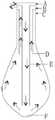
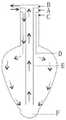
图1a为已有向盐穴正循环注水的方式示意;Figure 1a is a schematic diagram of the existing positive circulation water injection method to the salt cavern;
图1b为已有向盐穴反循环注水的方式示意;Figure 1b is a schematic diagram of the existing reverse circulation water injection method to the salt cavern;
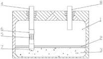
图2为本发明一实施例盐穴储气库腔体主视半剖视结构示意图;Fig. 2 is a schematic diagram of a half-section structure of a cavity of a salt cavern gas storage according to an embodiment of the present invention;
图3为本发明一实施例盐穴储气库腔体上设有管柱装置及注气层压套管的俯视结构示意图;Fig. 3 is a top view structure schematic diagram of a salt cavern gas storage cavity provided with a pipe string device and a gas injection laminated casing according to an embodiment of the present invention;
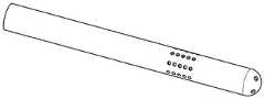
图4为本发明另一实施例管柱装置的结构示意图;Fig. 4 is a schematic structural view of a string device according to another embodiment of the present invention;
附图标号:Figure number:
A、淡水注入口,B、卤水排出口,C、油或气垫层注入口,D、中间管,E、中心管,F、底坑;A. Fresh water injection port, B. Brine discharge port, C. Oil or air cushion layer injection port, D. Intermediate pipe, E. Central pipe, F, Bottom pit;
1、盐穴储气库腔体,2、卤水层,3、不溶物层,4、射流套管,5、防砂筛管,6、密封滑套,7、喷头,8、注气层压套管。1. Salt cavern gas storage cavity, 2. Brine layer, 3. Insoluble matter layer, 4. Jet casing, 5. Sand control screen, 6. Sealing sleeve, 7. Nozzle, 8. Gas injection lamination sleeve Tube.
具体实施方式Detailed ways
以下将结合附图对本发明的较佳实施例进行详细说明,以便更清楚理解本发明的目的、特点和优点。应理解的是,附图所示的实施例并不是对本发明范围的限制,而只是为了说明本发明技术方案的实质精神。Preferred embodiments of the present invention will be described in detail below with reference to the accompanying drawings, so as to better understand the purpose, features and advantages of the present invention. It should be understood that the embodiments shown in the drawings are not intended to limit the scope of the present invention, but only to illustrate the essence of the technical solutions of the present invention.
在以往的盐穴储气库中,在判断储气库的容积及底部位置时,通过如图1a所示正循环或如图1b所示反循环注水的方式,通过淡水注入口A将目标储气库内部注满卤水,等待盐溶物逐渐溶解,但仍有部分不溶于水的固体不溶物直接脱落至储气库底部,形成一层沉积层。等到储气库成腔时,通过油或气垫层注入口C以注气增压的方式进行注气并通过卤水排出口B排出卤水的作业工程,但是由于下入套管与沉积层之间存在一定距离,导致卤水不能够完全排除,储气库中从上至下同时存在气层、水层和不溶层。不溶层位于底坑F处。In the conventional salt cavern gas storage, when judging the volume and bottom position of the gas storage, the target gas storage is injected through the fresh water injection port A by means of positive circulation as shown in Figure 1a or reverse circulation as shown in Figure 1b. The interior of the gas storage is filled with brine, and the salt-soluble matter is gradually dissolved, but some solid insoluble matter that is insoluble in water still falls off directly to the bottom of the gas storage, forming a layer of sediment. When the cavity of the gas storage is formed, gas injection is carried out through the injection port C of the oil or gas cushion layer, and the brine is discharged through the brine discharge port B. However, due to the presence of Due to a certain distance, the brine cannot be completely removed, and there are gas layers, water layers and insoluble layers in the gas storage from top to bottom. The insoluble layer is located at pit F.
上述方案中管柱装置可主要包括如图1a或1b所示的嵌套的中间管D和中心管E。The string device in the above solution may mainly include nested intermediate pipe D and center pipe E as shown in Fig. 1a or 1b.
针对套管继续深入的工程方案中,打桩法相对普遍,打桩法就是运用锤击的方式,将套管以外力的作用垂直下入目标地层,但是由于锤击的力量和地层中土壤的摩擦阻力,导致此方法需要消耗大量的人力物力及财力。In the project plan for further deepening of the casing, the piling method is relatively common. The piling method is to use the hammering method to vertically lower the casing into the target formation under the action of external force. However, due to the force of the hammering and the frictional resistance of the soil in the formation , causing this method to consume a lot of manpower, material and financial resources.
鉴于采用重锤法或旋转管柱的方法使管柱装置进入沉积层时,由于岩土的摩擦系数较大,导致管柱装置不能下入沉积层较深区域的位置,本发明提出了一种采用喷射方式使管柱装置下沉的装置及系统及使用方法,也就是使得管柱装置本身可以注入高压液体,采用喷射液体的方式,使得高压液体冲击沉积层,在沉积层上形成孔体,管柱装置就可顺着形成的孔体下沉,从而能下至更深的区域,进而能通过管柱装置排出更多的盐穴储气库内的液体,该液体通常为水。In view of the fact that when the pipe string device enters the sedimentary layer by using the hammer method or the method of rotating the pipe string, the pipe string device cannot be lowered into the deep area of the sedimentary layer due to the large friction coefficient of the rock and soil, the present invention proposes a The device, system and method of using the injection method to sink the pipe string device, that is, the pipe string device itself can be injected with high-pressure liquid, and the liquid is sprayed to make the high-pressure liquid impact the sediment layer and form pores on the sediment layer. The pipe string device can sink along the formed hole body, so as to go down to a deeper area, and then more liquid in the salt cavern gas storage can be discharged through the pipe string device, and the liquid is usually water.
本发明首先提出一种用于盐穴储气库的管柱装置,所述管柱装置包括:The present invention first proposes a pipe string device for a salt cavern gas storage, the pipe string device includes:
射流套管4,其被配置为设有射流通道;a
喷头7,其包括喷射孔71,该喷头设于射流套管4的下端,其连通射流通道,该喷头7被配置为具有打开和关闭两种状态;
筛孔部,其包括筛孔51,筛孔部设于射流套管4的套管壁,该筛孔部被配置为具有打开和关闭两种状态,当其处于打开状态时,筛孔51连通射流套管4的射流通道与外部,当其处于关闭状态时,筛孔51断开射流套管4的射流通道与外部的连通。A sieve part, which includes a sieve hole 51, the sieve part is arranged on the casing wall of the
当使筛孔部处于关闭状态,使喷头7处于打开状态时,通过射流通道注入液体,并使液体通过喷头7喷出,以使喷头7及管柱装置整体沿喷射方向移动;When the sieve portion is in the closed state and the
当使筛孔部处于打开状态,使喷头7处于关闭状态时,增大管柱装置所处环境的气压,使得筛孔部外的液体通过筛孔51流入射流通道,并从射流通道的上端排出,就可将盐穴内的液体排出。When the sieve portion is in the open state and the
根据本发明的一种实施方式,喷头7还包括外壳或内套,外壳上设有外孔或内套上设有内孔,外壳或内套被配置为能绕喷射孔旋转,外孔或内孔在外壳或内套旋转至其中一种状态时与喷射孔71连通,使得可以通过喷射孔71喷射液体,如高压水;在其他状态,外壳或内套遮挡喷射孔71,使得无法通过喷射孔喷射液体。According to one embodiment of the present invention, the
根据本发明的一种实施方式,外壳或内套的旋转可通过电路控制模块控制电机驱动装置实现。According to one embodiment of the present invention, the rotation of the outer shell or the inner sleeve can be realized by controlling the motor drive device through the circuit control module.
电机驱动装置可设置在管柱装置的上端(图上未示出),其输出轴连接外壳或内套,电机旋转时带动外壳或内套相对射流套管4旋转,从而实现外壳或内套与喷射孔71的遮挡状态或连通状态。对于本领域技术人员来说,此种实现方式可通过现有技术来实现,故此处不再赘述。The motor drive device can be arranged on the upper end of the pipe string device (not shown in the figure), and its output shaft is connected to the outer shell or the inner sleeve. When the motor rotates, the outer shell or the inner sleeve is driven to rotate relative to the
当然,外壳或内套的旋转也可通过其他现有技术实现,上述方式不作为本发明的限制。Certainly, the rotation of the outer casing or the inner casing can also be realized by other existing technologies, and the above-mentioned method is not a limitation of the present invention.
电路控制模块与电机驱动装置电连接。The circuit control module is electrically connected with the motor driving device.
电路控制模块的开关可设置在管柱装置上,或设计为遥控式的,可通过远程操作来控制管柱装置的动作。The switch of the circuit control module can be set on the pipe string device, or designed as a remote control type, and the action of the pipe string device can be controlled through remote operation.
根据本发明的一种实施方式,喷射孔71设于射流套管4上或者设于单独件上,该单独件与射流套管4连接。According to one embodiment of the present invention, the injection holes 71 are arranged on the
根据本发明的一种实施方式,如图2所示,筛孔部包括防砂筛管5和密封滑套6,防砂筛管5上设有筛孔51,密封滑套6设于防砂筛管5外部或内部,密封滑套6被配置为能相对防砂筛管5沿轴向滑动。当密封滑套6滑离防砂筛管5一定距离时,密封滑套6不再遮挡筛孔51,从而筛孔51连通射流通道的内外,而当密封滑套6滑近防砂筛管5并遮挡住筛孔51时,密封滑套6将筛孔所在部位的射流通道密封,从而不能使得射流通道在此处与外部连通。According to one embodiment of the present invention, as shown in Figure 2, the screen hole part includes a sand control screen 5 and a sealing sliding sleeve 6, the sand control screen 5 is provided with a screen hole 51, and the sealing sliding sleeve 6 is arranged on the sand control screen 5 Externally or internally, the sliding sleeve 6 is configured to slide axially relative to the sand control screen 5 . When the sealing sliding sleeve 6 slides away from the sand control screen 5 for a certain distance, the sealing sliding sleeve 6 no longer blocks the screen hole 51, so that the screen hole 51 communicates with the inside and outside of the jet channel, and when the sealing sliding sleeve 6 slides close to the sand control screen 5 and blocks When the sieve hole 51 is held, the sealing sliding sleeve 6 seals the jet channel at the position of the sieve hole, so that the jet channel cannot communicate with the outside here.
根据本发明的一种实施方式,密封滑套6的滑动可通过电路控制模块控制液压活塞装置上下往复运动来带动其实现。According to an embodiment of the present invention, the sliding of the sealing sliding sleeve 6 can be driven by the circuit control module to control the hydraulic piston device to reciprocate up and down.
通过液压活塞装置上下往复运动来带动密封滑套6滑动时,可通过电路控制模块控制进油管上的电动控制阀开启,进油管内的压力液通过压力液通道推动液压活塞下行,带动密封滑套6下行滑动,或者可通过电路控制模块控制回油管上的电动控制阀开启,压力液通过回油管路回流推动液压活塞上行,带动密封滑套6上行滑动。进油管、回油管、电动控制阀及液压活塞可设置在管柱装置上端。对于本领域技术人员来说,该种实现方式可通过现有技术来实现,故此处不再赘述。When the hydraulic piston device reciprocates up and down to drive the sealing sleeve 6 to slide, the electric control valve on the oil inlet pipe can be controlled to open through the circuit control module, and the pressure fluid in the oil inlet pipe pushes the hydraulic piston down through the pressure fluid channel to drive the sealing sleeve 6 slides downward, or the electric control valve on the oil return pipe can be controlled to open through the circuit control module, and the pressure fluid flows back through the oil return pipe to push the hydraulic piston upward, driving the sealing sliding sleeve 6 to slide upward. Oil inlet pipe, oil return pipe, electric control valve and hydraulic piston can be arranged on the upper end of the pipe string device. For those skilled in the art, such an implementation manner can be implemented through existing technologies, so details will not be repeated here.
当然,密封滑套6的滑动也可通过其他现有技术实现,上述方式不作为本发明的限制。Of course, the sliding of the sealing sliding sleeve 6 can also be realized by other existing technologies, and the above-mentioned method is not a limitation of the present invention.
根据本发明的一种实施方式,防砂筛管5为射流套管4的一部分或与所述射流套管为分体件,该防砂筛管5设置于射流套管4的上下两段之间。According to one embodiment of the present invention, the sand control screen 5 is a part of the
根据本发明的一种实施方式,喷射孔71包括一组孔眼,优选为四个。According to an embodiment of the present invention, the injection hole 71 includes a group of holes, preferably four.
根据本发明的一种实施方式,所述筛管为烧结滤网筛管,过滤层由烧结滤网构成,过流面积大,强度高,具有耐冲击耐腐蚀和较好的防堵能力,过流面积可达20%,能实现的防砂粒径在0.1mm以上。According to one embodiment of the present invention, the screen tube is a sintered filter screen tube, and the filter layer is composed of a sintered filter screen, which has a large flow area, high strength, impact resistance, corrosion resistance, and better anti-blocking ability. The flow area can reach 20%, and the sand control particle size that can be realized is above 0.1mm.
如图4所示,该管柱装置的射流套管4上设有筛孔51和喷射孔71。As shown in FIG. 4 , the
本发明还提出一种使用所述用于盐穴储气库的管柱装置的方法,所述方法主要包括:The present invention also proposes a method for using the pipe string device for a salt cavern gas storage, the method mainly comprising:
使所述筛孔部处于关闭状态,使所述喷头处于打开状态,通过所述射流通道注入液体,并使所述液体通过喷头喷出,以使所述喷头及管柱装置整体沿喷射方向移动;Make the sieve part in the closed state, make the spray head in the open state, inject liquid through the jet channel, and let the liquid spray out through the spray head, so that the spray head and the column device as a whole move along the spray direction ;
使所述筛孔部处于打开状态,使所述喷头处于关闭状态,增大所述管柱装置所处环境的气压,使得所述筛孔部外的液体通过筛孔流入所述射流通道,并从所述射流通道的上端排出。Keeping the sieve part in an open state, making the spray head in a closed state, increasing the air pressure of the environment where the pipe string device is located, so that the liquid outside the sieve part flows into the jet channel through the sieve hole, and Discharge from the upper end of the jet channel.
根据本发明的一种实施方式,可通过遥控的方式控制喷头7的外壳或内套旋转,以使喷头7处于打开状态或关闭状态。当然也可通过管柱装置上设置的开关启动或关闭喷头。According to one embodiment of the present invention, the rotation of the outer casing or the inner casing of the
根据本发明的一种实施方式,可通过遥控的方式控制所述筛孔部的密封滑套沿轴向滑动,以使所述筛孔部处于打开状态或关闭状态。当然也可通过管柱装置上设置的滑动按键滑动密封滑套。According to an embodiment of the present invention, the sealing sliding sleeve of the sieve portion can be controlled to slide axially through remote control, so that the sieve portion is in an open state or a closed state. Of course, the sealing sliding sleeve can also be slid through the sliding button arranged on the pipe string device.
本发明还提出一种用于盐穴储气库排卤增容系统,如图2、图3所示,该系统主要包括注气增压套管8和上述的用于盐穴储气库的管柱装置,管柱装置与注气增压套管8分别连通盐穴储气库,管柱装置被配置为对盐穴储气库进行喷射融化盐矿的液体及排液,注气增压套管8被配置为向盐穴储气库注入气体,以增加盐穴储气库内的气压。The present invention also proposes a brine discharge and capacity-increasing system for salt cavern gas storage, as shown in Figure 2 and Figure 3, the system mainly includes gas injection pressurized
本发明还提出一种储气库排卤增容的方法,所述方法包括:将管柱装置与注气增压套管分别连通盐穴储气库,通过向所述管柱装置内注入液体以使所述管柱装置以喷射的方式向所述盐穴储气库底行进,并通过所述管柱装置射出的液体对所述盐穴储气库的盐矿进行融化,待盐矿融化后通过所述注气增压套管向所述盐穴储气库注入气体,以增加所述盐穴储气库内的气压,并通过所述管柱装置吸入融化的液体进行排液,从而达到对所述储气库排卤并增容的目的。The present invention also proposes a method for increasing the capacity of a gas storage by exhausting brine. The method includes: connecting the pipe string device and the gas injection booster casing to the salt cavern gas storage respectively, and injecting liquid into the pipe string device The pipe string device advances toward the bottom of the salt cavern gas storage in a spraying manner, and the liquid injected by the pipe string device melts the salt mine in the salt cavern gas storage, and the salt mine melts Then inject gas into the salt cavern gas storage through the gas injection pressurization sleeve to increase the air pressure in the salt cavern gas storage, and suck the melted liquid through the pipe string device to discharge liquid, thereby The purpose of exhausting halogen and increasing the capacity of the gas storage is achieved.
本发明可通过射流的方式让管柱装置进入更深层的沉积物中,从而可以排除更多的水量,进而更为有效地增大了储存空间,即增大了储气库的容积量,实现了扩容,对盐穴储气库的建设意义重大。The present invention can allow the pipe string device to enter deeper sediments by means of jet flow, so that more water can be removed, thereby increasing the storage space more effectively, that is, increasing the volume of the gas storage, and realizing In addition to capacity expansion, it is of great significance to the construction of salt cavern gas storage.
实施例1Example 1
如图2、3所示,一种适用于储气库的喷射管柱装置,主要包括射流套管4,防砂筛管5,密封滑套6,含闭口性能的水力喷头7,其中密封滑套6用于开启和关闭防砂筛管5的使用。可通过水力喷射方式将管柱装置下入到盐穴储气库中的不溶物层3当中。当射流套管4稳定不再下降之后,通过另一井进行注气增压的方式,排出盐穴储气库腔体内多余的卤水,可有效增加腔体由于水量过多导致的容积变小的问题。As shown in Figures 2 and 3, an injection string device suitable for gas storage mainly includes a
本实施方式一种通过水力喷射方式将管柱装置下入到盐穴储气库底层不溶物中的工艺流程,此工艺需以双井(一个井下放管柱装置,另一个井用于插入注气增压套管8)建腔,其中:This embodiment is a technological process for lowering the pipe string device into the insoluble material at the bottom of the salt cavern gas storage by means of hydraulic jetting. Gas pressurized casing 8) build cavity, wherein:
射流套管4,用来提供水力喷射的流体流动区域;
其中防砂筛管5安装在射流套管4壁上,密封滑套6用于开启和关闭防砂筛管5功能的使用,密封滑套6可通过电信号传输的方式被控制进行上下滑动,密封滑套6和防砂筛管5处于同一水平位置时,管壁内外两侧由于密封滑套的阻隔,水流无法进行连通流动,使射流套管4处于密封关闭状态,水流仅可沿管壁内部流动;当密封滑套6向上(或向下)滑动时,管壁内外两侧的阻隔被消除,安装在套管壁上的防砂筛管5使水可以流通于射流套管内外两侧,并同时进行防砂处理;Among them, the sand control screen 5 is installed on the wall of the
含闭口性能的四孔水力喷头7,水力喷头的外侧由可旋转的四孔密封外壳覆盖,通过旋转的方式实现密封特性,旋转方式可由电信号传输的方式进行实况控制操作,当水力喷头的密封外壳为0°时,密封外壳堵住水力喷头的喷射孔,达到密封特性,当其旋转90°时,密封外壳的四孔与四孔水力喷头连通,实现喷射特性。The four-hole
进行下套管工艺技术,需要对管柱装置进行水力喷射,打开水力喷头7,关闭密封滑套6,进行水力喷射并将射流套管4下入盐穴储气库中的不溶物层3当中,当套管不再下降时,停止水力喷射,关闭水力喷头7。To carry out the casing running technology, it is necessary to perform hydraulic injection on the pipe string device, open the
进行注气加压排卤工艺技术,根据双井建腔原理,当射流套管4已经沉入地层不溶物层3当中,注气增压套管8开始进行注气加压准备排出卤水的工程作业方式;Carry out gas injection and pressurization brine discharge process technology, according to the principle of double well cavity construction, when the
关闭水力喷头7,将密封滑套6向上(或向下)移动,防砂筛管5的功能启用,腔体内多余的水及其较小直径的颗粒将会由于压力的作用沿着射流套管4内流动而被排出腔体,扩大了腔体的容积,故能够储存更多的天然气。Close the
实施例2Example 2
在打桩法动力沉降过程中,桩内土塞达到一定深度,导致桩摩阻力增大,沉桩效率变低。而水射流的方法可降低桩体由于进入土层中所导致的摩阻力,扰动桩端土体,降低地层强度,使桩快速下沉至设计深度。因高压水的喷射力很强,各种土体都能很快松动,除较大的粗砂、砾石留在孔底外,一般土壤颗粒都能被高压水流冲散,实现高效率的沉桩过程。以下实验数据进一步证明了本发明采用方法的有效性。During the dynamic settlement process of the pile driving method, the soil plug in the pile reaches a certain depth, which leads to the increase of the pile frictional resistance and the low pile sinking efficiency. The water jet method can reduce the frictional resistance caused by the pile body entering the soil layer, disturb the soil at the pile end, reduce the strength of the ground, and make the pile quickly sink to the design depth. Due to the strong jetting force of high-pressure water, all kinds of soil can be quickly loosened. Except for large coarse sand and gravel left at the bottom of the hole, general soil particles can be washed away by high-pressure water to achieve high-efficiency pile sinking process. The following experimental data further proves the effectiveness of the method adopted by the present invention.
表1不同射流压力下锤击数Table 1 Number of hammer blows under different jet pressures
Tab.1 Hammering number under different jet pressuresTab.1 Hammering number under different jet pressures

表1:无射流沉桩从0.35m至0.95m需要锤击数为263次,而在有射流辅助沉桩下,当压力为0.02MPa时,约186次锤击即可完成沉桩过程,当压力达到0.57MPa时,只需要大约113次。可见射流辅助沉桩条件下沉桩效率比无射流沉桩大大提高。Table 1: Pile sinking without jet requires 263 times of hammering from 0.35m to 0.95m, while under jet-assisted pile sinking, when the pressure is 0.02MPa, about 186 times of hammering can complete the pile sinking process, when When the pressure reaches 0.57MPa, only about 113 times are required. It can be seen that the efficiency of pile sinking under the condition of jet-assisted pile sinking is greatly improved compared with that of pile sinking without jet.
表2不同流量射流锤击数Table 2 The number of jet hammer blows with different flow rates
Tab.2 Hammering number under different iet flowsTab.2 Hammering number under different iet flows

表2:沉桩0.60m从0.35m至0.95m,流量25L/min时需要锤击数为199次,而流量30L/min时需要锤击数为113次,二者相差86次。说明在模拟地层、喷头原理样机等条件均相同的条件下,加大流量所需锤击数较少,进而说明,在射流辅助沉桩过程中,如果地层较硬,可通过加大射流流量的方法来提高沉桩效率。Table 2: Pile sinking 0.60m from 0.35m to 0.95m, when the flow rate is 25L/min, the number of hammering times is 199, while when the flow rate is 30L/min, the number of hammering times is 113 times, with a difference of 86 times. It shows that under the same conditions as the simulated strata and the principle prototype of the sprinkler, the number of hammer blows required to increase the flow rate is less, and further shows that in the process of jet-assisted pile sinking, if the stratum is hard, it can be improved by increasing the jet flow rate. method to improve pile sinking efficiency.
由此数据可分析得出,水力喷射的方法将会比打桩更容易下入地层深处。From this data, it can be analyzed that the method of hydrojet will be easier to go into the depth of the formation than piling.
以上所述仅为本发明的较佳实施方案,并不用以限制本发明,凡在本发明的精神和原则之内,所作的任何修改、等同替换等,均应包含在本发明的保护范围之内。The above is only a preferred embodiment of the present invention, and is not intended to limit the present invention. Any modifications, equivalent replacements, etc. made within the spirit and principles of the present invention should be included in the protection scope of the present invention Inside.
需要说明的是,在本文中,术语“中心”、“上”、“下”、“左”、“右”、“竖直”、“水平”、“内”、“外”等指示的方位或位置关系为基于附图所示的方位或位置关系,仅是为了便于描述本发明和简化描述,而不是指示或暗示所指的系统或元件必须具有特定的方位、以特定的方位构造和操作,因此不能理解为对本发明的限制;诸如“第一”和“第二”等之类的关系术语仅仅用来将一个实体或者操作与另一个实体或操作区分开来,而不一定要求或者暗示这些实体或操作之间存在任何这种实际的关系或者顺序。而且,术语“包括”、“包含”或者其任何其他变体意在涵盖非排他性的包含,从而使得包括一系列要素的过程、方法、物品或者设备不仅包括那些要素,而且还包括没有明确列出的其他要素,或者是还包括为这种过程、方法、物品或者设备所固有的要素。在没有更多限制的情况下,由语句“包括一个……”限定的要素,并不排除在包括所述要素的过程、方法、物品或者设备中还存在另外的相同要素。It should be noted that, in this document, the terms "center", "upper", "lower", "left", "right", "vertical", "horizontal", "inner", "outer" and the like indicate directions Or the positional relationship is based on the orientation or positional relationship shown in the drawings, which are only for the convenience of describing the present invention and simplifying the description, rather than indicating or implying that the system or element referred to must have a specific orientation, be constructed and operated in a specific orientation , and therefore should not be construed as limiting the invention; relational terms such as "first" and "second" are used only to distinguish one entity or operation from another, and do not necessarily require or imply There is no such actual relationship or order between these entities or operations. Furthermore, the term "comprises", "comprises" or any other variation thereof is intended to cover a non-exclusive inclusion such that a process, method, article, or apparatus comprising a set of elements includes not only those elements, but also includes elements not expressly listed. other elements of or also include elements inherent in such a process, method, article, or device. Without further limitations, an element defined by the phrase "comprising a ..." does not exclude the presence of additional identical elements in the process, method, article or apparatus comprising said element.
此外,在本发明的描述中,需要说明的是,除非另有明确的规定和限定,术语“安装”、“相连”、“连接”应做广义理解,例如,可以是固定连接,也可以是可拆卸连接,或一体地连接;可以是机械连接,也可以是电连接;可以是直接相连,也可以通过中间媒介间接相连,可以是两个元件内部的连通。对于本领域的普通技术人员而言,可以具体情况理解上述术语在本发明中的具体含义。In addition, in the description of the present invention, it should be noted that unless otherwise specified and limited, the terms "installation", "connection" and "connection" should be understood in a broad sense, for example, it can be a fixed connection or a A detachable connection, or an integral connection; it may be a mechanical connection or an electrical connection; it may be a direct connection or an indirect connection through an intermediary, and it may be an internal communication between two components. Those of ordinary skill in the art can understand the specific meanings of the above terms in the present invention in specific situations.
上述各实施例仅用于说明本发明,其中实施例的各零部件、装置都是可以有所变化的,各实施方式都可根据需要进行组合或删减,附图中并非所有部件都是必要设置,本文中所定义的一般原理可以在不脱离本申请的精神或范围的情况下,在其它实施例中实现。因此,本申请将不会被限制于本文所述的这些实施例,凡是在本发明技术方案的基础上进行的等同变换和改进,均不应排除在本发明的保护范围之外。The above-mentioned embodiments are only used to illustrate the present invention, and the components and devices of the embodiments can be changed, and the various implementation modes can be combined or deleted as required, and not all parts are necessary in the accompanying drawings. configuration, the general principles defined herein may be implemented in other embodiments without departing from the spirit or scope of the present application. Therefore, the present application will not be limited to these embodiments described herein, and all equivalent transformations and improvements made on the basis of the technical solution of the present invention shall not be excluded from the protection scope of the present invention.
Claims (8)
Priority Applications (1)
| Application Number | Priority Date | Filing Date | Title |
|---|---|---|---|
| CN202110376957.6ACN113153228B (en) | 2021-04-08 | 2021-04-08 | System for discharging brine and increasing capacity of gas storage, tubular column device and using method of system |
Applications Claiming Priority (1)
| Application Number | Priority Date | Filing Date | Title |
|---|---|---|---|
| CN202110376957.6ACN113153228B (en) | 2021-04-08 | 2021-04-08 | System for discharging brine and increasing capacity of gas storage, tubular column device and using method of system |
Publications (2)
| Publication Number | Publication Date |
|---|---|
| CN113153228A CN113153228A (en) | 2021-07-23 |
| CN113153228Btrue CN113153228B (en) | 2022-11-29 |
Family
ID=76889278
Family Applications (1)
| Application Number | Title | Priority Date | Filing Date |
|---|---|---|---|
| CN202110376957.6AActiveCN113153228B (en) | 2021-04-08 | 2021-04-08 | System for discharging brine and increasing capacity of gas storage, tubular column device and using method of system |
Country Status (1)
| Country | Link |
|---|---|
| CN (1) | CN113153228B (en) |
Families Citing this family (2)
| Publication number | Priority date | Publication date | Assignee | Title |
|---|---|---|---|---|
| CN116411913B (en)* | 2021-12-31 | 2025-09-12 | 核工业北京化工冶金研究院 | An integrated automatic control device for gas injection in in-situ leaching of uranium |
| CN116517478A (en)* | 2023-06-07 | 2023-08-01 | 山东科技大学 | Water-soluble cavitation string and cavitation device for salt cavern energy storage |
Citations (2)
| Publication number | Priority date | Publication date | Assignee | Title |
|---|---|---|---|---|
| CN111672850A (en)* | 2020-06-11 | 2020-09-18 | 中国石油大学(北京) | Jet cleaning simulation experiment system for salt cavern gas storage |
| CN111852425A (en)* | 2019-04-24 | 2020-10-30 | 中国石油化工股份有限公司 | Hot dry rock staged fracturing pipe column and application method |
Family Cites Families (12)
| Publication number | Priority date | Publication date | Assignee | Title |
|---|---|---|---|---|
| US7097386B2 (en)* | 2003-11-13 | 2006-08-29 | Freeport-Mcmoran Energy Llc | Simultaneous development of underground caverns and deposition of materials |
| WO2010150010A2 (en)* | 2009-06-23 | 2010-12-29 | Bruce Arnold Tunget | Apparatus and methods for forming and using subterranean salt cavern |
| DE102009057534A1 (en)* | 2009-12-08 | 2011-06-09 | Kbb Underground Technologies Gmbh | Method for discharging sodium chloride brine of natural gas storage cavern, involves introducing gas into injection line for lifting brine, and continuously or discontinuously adding water for dilution of saturated brine to introduced gas |
| GB201019358D0 (en)* | 2010-11-16 | 2010-12-29 | Darcy Technologies Ltd | Downhole method and apparatus |
| CN102220842A (en)* | 2011-05-13 | 2011-10-19 | 张朝纯 | Radial high-pressure water jetting composite well with ultrashort radius as well as well completion tool and technology |
| CN202325434U (en)* | 2011-09-15 | 2012-07-11 | 西南石油大学 | Closable balancing sieve tube for horizontal wells and closing tool for closable balancing sieve tube |
| CN102979497A (en)* | 2012-11-20 | 2013-03-20 | 中国石油大学(北京) | Device and method for immovable-string type packer-free sliding-sleeve hydraulic-jet pulsed acid fracturing |
| US9045209B2 (en)* | 2013-03-14 | 2015-06-02 | Sanko Tekstil Isletmeleri Sanayi Ve Ticaret A.S. | Active volume energy level large scale sub-sea energy fluids storage methods and apparatus for power generation and integration of renewable energy sources |
| CN204041044U (en)* | 2014-09-01 | 2014-12-24 | 中国石油化工股份有限公司 | It is a kind of that rock salt underground natural gas storage tank is water-soluble makes lumen post waterpower stabilization control device |
| CN107152264B (en)* | 2017-06-16 | 2023-07-04 | 中国石油天然气股份有限公司西气东输管道分公司 | Coiled tubing string device and its method for brine discharge and expansion in salt cavern underground gas storage |
| CN109838279B (en)* | 2017-11-24 | 2021-04-13 | 江苏苏盐井神股份有限公司 | Method for improving salt cavern storage utilization rate by discharging brine from cavity bottom through communicating well |
| CN112227985B (en)* | 2020-10-12 | 2021-10-22 | 中国科学院武汉岩土力学研究所 | Full-horizontal section expansion method for brine mining in butt-joint wells of ultra-deep salt mines |
- 2021
- 2021-04-08CNCN202110376957.6Apatent/CN113153228B/enactiveActive
Patent Citations (2)
| Publication number | Priority date | Publication date | Assignee | Title |
|---|---|---|---|---|
| CN111852425A (en)* | 2019-04-24 | 2020-10-30 | 中国石油化工股份有限公司 | Hot dry rock staged fracturing pipe column and application method |
| CN111672850A (en)* | 2020-06-11 | 2020-09-18 | 中国石油大学(北京) | Jet cleaning simulation experiment system for salt cavern gas storage |
Also Published As
| Publication number | Publication date |
|---|---|
| CN113153228A (en) | 2021-07-23 |
Similar Documents
| Publication | Publication Date | Title |
|---|---|---|
| US10822927B2 (en) | Device and method for solid-state fluidized mining of natural gas hydrates in shallow seabed | |
| CN108756828B (en) | Method and system for solid-state fluidized recovery of hydrate under underbalanced reverse circulation | |
| RU2360100C2 (en) | Facility and methods for removing filter cake from uncased borehole of well | |
| CN112197448B (en) | Geothermal development system | |
| CN103104222B (en) | Ground peupendicular hole combines extraction coal bed gas method with concordant long drilled holes | |
| CN113153228B (en) | System for discharging brine and increasing capacity of gas storage, tubular column device and using method of system | |
| JP7299643B2 (en) | Offshore natural gas hydrate tubular mining equipment and method | |
| CN1756891A (en) | Advanced gas injection method and equipment and liquid hydrocarbon recovery system | |
| CN108678671A (en) | A kind of sea bed gas hydrate digging sleeve type injection retracting device | |
| CN112392484B (en) | A carbon dioxide phase transition cracking and anti-reflection device and working method without a pipe string | |
| CN205445569U (en) | Construction pipe column capable of realizing layering volume fracturing of directional well | |
| CN112983325B (en) | Horizontal well blockage removal and yield increase integrated process and system | |
| CN109372474B (en) | A kind of coal bed gas and sandstone gas are the same as well flow string and recovery method | |
| JP7297353B1 (en) | Natural gas hydrate - shallow gas - deep gas multi-source multi-method joint mining system and method | |
| CN104453798A (en) | PVC sleeve pipe waterpower sand blasting perforation device and using method thereof | |
| CN102312659A (en) | Pollution-free well workover process for oil field | |
| CN105756591A (en) | Coal bed gas well completion method | |
| CN210033856U (en) | Automatic desilting silt pump and rig | |
| CN211777348U (en) | Novel normal position of ocean natural gas hydrate is separated and is adopted device | |
| CN113914824A (en) | Well-flushing pump down-hole follow-up sealing production-increasing tubular column and efficient lifting method | |
| CN112780221B (en) | Reservoir pollution-free perforation-free cementing tool device and method | |
| CN113944451B (en) | Pneumatic rodless liquid discharge lifting pipe column and method for pneumatic production well | |
| CN205297495U (en) | Sand blasting perforator | |
| CN210134898U (en) | Self-flowing water injection well completion pipe string | |
| CN107869322A (en) | Drag for sand instrument in underground |
Legal Events
| Date | Code | Title | Description |
|---|---|---|---|
| PB01 | Publication | ||
| PB01 | Publication | ||
| SE01 | Entry into force of request for substantive examination | ||
| SE01 | Entry into force of request for substantive examination | ||
| GR01 | Patent grant | ||
| GR01 | Patent grant |