CN113146646B - A detection robot control system suitable for vehicle-mounted switchgear robot operation - Google Patents
A detection robot control system suitable for vehicle-mounted switchgear robot operationDownload PDFInfo
- Publication number
- CN113146646B CN113146646BCN202110093674.0ACN202110093674ACN113146646BCN 113146646 BCN113146646 BCN 113146646BCN 202110093674 ACN202110093674 ACN 202110093674ACN 113146646 BCN113146646 BCN 113146646B
- Authority
- CN
- China
- Prior art keywords
- switch cabinet
- detection
- robot
- carriage
- vehicle
- Prior art date
- Legal status (The legal status is an assumption and is not a legal conclusion. Google has not performed a legal analysis and makes no representation as to the accuracy of the status listed.)
- Active
Links
Images


Classifications
- B—PERFORMING OPERATIONS; TRANSPORTING
- B25—HAND TOOLS; PORTABLE POWER-DRIVEN TOOLS; MANIPULATORS
- B25J—MANIPULATORS; CHAMBERS PROVIDED WITH MANIPULATION DEVICES
- B25J11/00—Manipulators not otherwise provided for
- B—PERFORMING OPERATIONS; TRANSPORTING
- B25—HAND TOOLS; PORTABLE POWER-DRIVEN TOOLS; MANIPULATORS
- B25J—MANIPULATORS; CHAMBERS PROVIDED WITH MANIPULATION DEVICES
- B25J19/00—Accessories fitted to manipulators, e.g. for monitoring, for viewing; Safety devices combined with or specially adapted for use in connection with manipulators
- B25J19/0095—Means or methods for testing manipulators
- B—PERFORMING OPERATIONS; TRANSPORTING
- B25—HAND TOOLS; PORTABLE POWER-DRIVEN TOOLS; MANIPULATORS
- B25J—MANIPULATORS; CHAMBERS PROVIDED WITH MANIPULATION DEVICES
- B25J5/00—Manipulators mounted on wheels or on carriages
- B25J5/02—Manipulators mounted on wheels or on carriages travelling along a guideway
- B25J5/04—Manipulators mounted on wheels or on carriages travelling along a guideway wherein the guideway is also moved, e.g. travelling crane bridge type
- B—PERFORMING OPERATIONS; TRANSPORTING
- B25—HAND TOOLS; PORTABLE POWER-DRIVEN TOOLS; MANIPULATORS
- B25J—MANIPULATORS; CHAMBERS PROVIDED WITH MANIPULATION DEVICES
- B25J9/00—Programme-controlled manipulators
- B25J9/16—Programme controls
- B25J9/1602—Programme controls characterised by the control system, structure, architecture
Landscapes
- Engineering & Computer Science (AREA)
- Robotics (AREA)
- Mechanical Engineering (AREA)
- Automation & Control Theory (AREA)
- Manipulator (AREA)
- Automatic Assembly (AREA)
Abstract
Description
Translated fromChinese技术领域technical field
本发明涉及电气开关柜检测的技术领域,具体的,涉及一种适用于车载开关柜机器人运行的检测机器人控制系统。The invention relates to the technical field of electrical switchgear detection, in particular to a detection robot control system suitable for the operation of a vehicle-mounted switchgear robot.
背景技术Background technique
在电力系统中高低压开关柜是必不可少的装置,高低压开关柜对整个电力系统的正常运行以及电力分配都有非常重要的影响。高低压开关柜的主要作用是在电力系统进行发电、输电、配电和电能转换的过程中,进行开合、控制和保护用电设备,广泛适用于发电厂、变电站、石油化工、冶金轧钢、轻工纺织、厂矿企业和住宅小区、高层建筑等各种不同场所。The high and low voltage switchgear is an indispensable device in the power system. The high and low voltage switchgear has a very important impact on the normal operation of the entire power system and power distribution. The main function of high and low voltage switchgear is to open and close, control and protect electrical equipment during the process of power generation, transmission, distribution and power conversion in the power system. It is widely used in power plants, substations, petrochemicals, metallurgical rolling steel, Various places such as light industry textiles, factories and mines, residential quarters, high-rise buildings, etc.
开关柜在厂家生产的过程中由于设备、环境、人为等因素影响不可避免会产生某些缺陷。这些缺陷除了不能很好发挥开关柜隔离保护等作用,还可能会对电网产生负面影响,进而造成事故。During the production process of the switchgear, some defects will inevitably occur due to the influence of equipment, environment, human factors and other factors. In addition to not being able to play a good role in the isolation and protection of the switchgear, these defects may also have a negative impact on the power grid, thereby causing accidents.
因此,为了保证开关柜的生产质量,在投入使用前开关柜的检测工作必不可少。工作中需要对高、低压配电柜进行日常保养、一级维护、二级维护和进线开关的日常维护等方式进行维护。开关柜的检测通常是由人工完成的,由于开关柜质量大,工作环境危险,传统的人工检测的方式通常面临效率不高,工作环境恶劣的问题。Therefore, in order to ensure the production quality of the switchgear, it is essential to inspect the switchgear before it is put into use. During the work, it is necessary to carry out daily maintenance, primary maintenance, secondary maintenance, and routine maintenance of incoming line switches for high and low voltage power distribution cabinets. The detection of switchgear is usually done manually. Due to the high quality of the switchgear and the dangerous working environment, the traditional manual detection method usually faces the problems of low efficiency and harsh working environment.
发明内容Contents of the invention
本发明的目的在于解决现有技术的问题,提供一种适用于车载开关柜机器人运行的检测机器人控制系统。The purpose of the present invention is to solve the problems of the prior art, and provide a detection robot control system suitable for the operation of the vehicle-mounted switch cabinet robot.
本发明的目的通过以下技术方案予以实现:The purpose of the present invention is achieved through the following technical solutions:
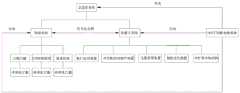
一种适用于车载开关柜机器人运行的检测机器人控制系统,包括总监控系统、和为总监控系统供电的UPS不间断电源系统;A detection robot control system suitable for the operation of a vehicle-mounted switch cabinet robot, including a general monitoring system and a UPS uninterruptible power supply system for powering the general monitoring system;
所述总监控系统包括检验系统和机器人系统,所述检验系统和机器人系统之间经由信号互反馈的方式以保证开关柜自动传输到检测中心的系统运行和检测的精度;The overall monitoring system includes an inspection system and a robot system, and the inspection system and the robot system use signal feedback to ensure the system operation and detection accuracy of the automatic transmission of the switchgear to the inspection center;
所述检验系统包括用于检测开关柜品质的检测传感器及其终端执行器构成;The inspection system includes a detection sensor and an end effector for detecting the quality of the switch cabinet;
所述机器人系统包括:The robotic system includes:
(1)柜门自动打开装置,实现将开关柜的断路器格室和母线格室的柜门打开和关闭,以方便检验系统对开关柜的内外部检测;(1) The automatic opening device of the cabinet door realizes the opening and closing of the cabinet doors of the circuit breaker compartment and the busbar compartment of the switch cabinet, so as to facilitate the inspection system to detect the inside and outside of the switch cabinet;
(2)开关柜自动提升装置,实现开关柜的提升和降落,以及从汽车尾板输送到过渡滚筒装置;(2) The automatic lifting device of the switch cabinet realizes the lifting and lowering of the switch cabinet, and conveys from the tail plate of the car to the transition roller device;
(3)过渡滚筒装置,实现将开关柜从设有动力滚筒装置的汽车尾板传送到检测平台;(3) Transition roller device, which realizes the transfer of the switchgear from the tailgate of the vehicle equipped with the power roller device to the detection platform;
(4)旋转定位装置,实现开关柜的四周旋转以进行后续的扫描检验;(4) The rotating positioning device realizes the rotation of the switchgear around for subsequent scanning inspection;
(5)以及可扩容车辆结构,提供大尺寸开关柜或开关柜位于检测平台进行全周检测时,车厢内有足够容纳的空间。(5) As well as the expandable vehicle structure, when a large-size switchgear or a switchgear is located on the detection platform for full-circle detection, there is enough space in the compartment.
进一步地,所述检验系统包括:Further, the inspection system includes:
(1)对开关柜综合性能进行检测的三维扫描检测系统及其终端执行器,(1) The three-dimensional scanning detection system and its terminal actuator for detecting the comprehensive performance of the switchgear,
(2)对开关柜二维码的拍摄扫描及其箱体检测的CCD检测系统及其终端执行器,(2) The CCD detection system for shooting and scanning the two-dimensional code of the switch cabinet and its box body detection and its terminal actuator,
(3)对开关柜母线表面的材质检测系统及其终端执行器。(3) The material detection system and its terminal actuator on the surface of the switchgear busbar.
进一步地,柜门自动打开装置包括安装于车厢底板上的水平移动导轨和沿水平移动导轨运动的水平移动滑块、固定在水平移动滑块上的垂直立柱导轨和沿垂直立柱导轨运动的垂直移动滑块、安装在垂直移动滑块上的工业机器人,所述工业机器人的操作端连接真空吸盘装置;所述水平移动导轨和垂直立柱导轨上设有驱动滑块运动的伺服电机。Further, the automatic opening device for the cabinet door includes a horizontally moving guide rail mounted on the carriage floor, a horizontally moving slider moving along the horizontally moving guide rail, a vertical column guide rail fixed on the horizontally moving slider, and a vertically moving slider moving along the vertical column guide rail. The slider is an industrial robot installed on the vertically moving slider, and the operating end of the industrial robot is connected to a vacuum suction cup device; the horizontal moving guide rail and the vertical column guide rail are provided with a servo motor that drives the slider to move.
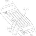
进一步地,所述开关柜自动提升装置包括与车厢刚性连接的液压缸组件、通过旋转铰链与液压缸组件铰接的汽车尾板,以及设置在汽车尾板上的动力滚筒装置;Further, the switchgear automatic lifting device includes a hydraulic cylinder assembly rigidly connected to the vehicle compartment, an automobile tailgate hinged to the hydraulic cylinder assembly through a rotary hinge, and a power roller device arranged on the automobile tailgate;
所述动力滚筒装置包括底部框架,和设置在底部框架上由动力驱动往返的动力滚筒组件;The power roller device includes a bottom frame, and a power roller assembly arranged on the bottom frame and driven back and forth by power;
所述动力滚筒组件包括两台相对设置在边框上的伺服电机、以及一排两端活动设置在边框上的滚筒。The power roller assembly includes two servo motors arranged oppositely on the frame, and a row of rollers whose two ends are movably arranged on the frame.
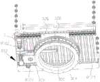
进一步地,所述旋转定位装置包括齿轮回转支承、驱动齿轮回转支承的伺服电机和减速机、检测平台,以及定位传感器;Further, the rotation positioning device includes a gear slewing bearing, a servo motor and a reducer for driving the gear slewing bearing, a detection platform, and a positioning sensor;
所述检测平台安装于齿轮回转支承上,由伺服电机和减速机驱动齿轮回转支承,带动检测平台转动;The detection platform is installed on the gear slewing support, and the gear slewing support is driven by the servo motor and the reducer to drive the detection platform to rotate;
所述定位传感器分别检测平台的四个方位,通过分析所述的定位传感器间的相对坐标关系,实现检测平台的定位;The positioning sensors respectively detect the four orientations of the platform, and realize the positioning of the detection platform by analyzing the relative coordinate relationship between the positioning sensors;
所述检测平台包括动力滚筒组件;所述动力滚筒组件包括两台相对设置在边框上的伺服电机、以及一排两端活动设置在边框上的滚筒。The detection platform includes a power roller assembly; the power roller assembly includes two servo motors arranged oppositely on the frame, and a row of rollers with both ends movably arranged on the frame.
进一步地,所述滚筒的两个端部设有齿轮,所述滚筒之间的齿轮相互啮合,滚筒的齿轮与伺服电机的齿轮啮合,由伺服电机驱动;Further, the two ends of the rollers are provided with gears, the gears between the rollers mesh with each other, the gears of the rollers mesh with the gears of the servo motor, and are driven by the servo motor;
相邻滚筒之间的齿轮分别为与滚筒刚性连接和活动连接,实现所有滚筒有相同的转动方向。The gears between adjacent rollers are respectively rigidly connected and flexibly connected with the rollers, so that all the rollers have the same rotation direction.
进一步地,所述过渡滚筒装置包括升降台、滚筒、伺服电机、轴承座、联轴器;Further, the transition roller device includes a lifting platform, a roller, a servo motor, a bearing seat, and a coupling;
所述升降台与车厢刚性连接,由伺服电机驱动升降;所述滚筒通过轴承座设置在边框上,由伺服电机驱动。The lifting platform is rigidly connected with the carriage, and is driven to lift by a servo motor; the roller is set on the frame through a bearing seat, and is driven by a servo motor.
进一步地,所述可扩容车辆结构包括车厢顶板、车厢侧板和车厢底板,所述车厢顶板通过至少4个伸缩立柱支撑,所述伸缩立柱与车辆底架固定连接;所述车厢侧板呈“L”型,包括嵌套底板和侧板;所述车厢底板安装在车辆底架上,所述嵌套底板与车厢底板采用嵌套连接,通过侧板调整装置控制嵌套底板与车厢底板间的嵌套距离调节车厢宽度;所述车厢顶板包括车厢柱顶板和两侧的翼板,所述车厢柱顶板和两侧的翼板铰接,并设有翼板调整装置来调节翼板张开幅度;Further, the expandable vehicle structure includes a compartment roof, a compartment side panel and a compartment floor, the compartment roof is supported by at least 4 telescopic uprights, and the telescopic uprights are fixedly connected to the vehicle chassis; the compartment side panels are in the shape of " L" type, including a nested bottom plate and a side plate; the car floor is installed on the vehicle chassis, the nested bottom plate and the car floor are connected by nesting, and the side plate adjustment device controls the distance between the nested bottom plate and the car floor. The nesting distance adjusts the compartment width; the compartment roof includes the compartment column top plate and the wing plates on both sides, the compartment column top plate and the wing plates on both sides are hinged, and a wing plate adjustment device is provided to adjust the opening range of the wing plates;
所述伸缩立柱、侧板调整装置、翼板调整装置为液压驱动,通过液压同步系统实现车厢的同步顶升和展开。The telescopic column, the side plate adjustment device, and the wing plate adjustment device are hydraulically driven, and the synchronous jacking and unfolding of the carriages are realized through the hydraulic synchronization system.
进一步地,终端执行器包括实现3个垂直方向和1个旋转方向运动的四自由度移动平台、工业机器人,所述工业机器人的操作端用于安装检测传感器。Further, the end effector includes a four-degree-of-freedom mobile platform that can move in three vertical directions and one rotational direction, and an industrial robot. The operating end of the industrial robot is used to install detection sensors.
进一步地,总监控系统控制伺服电机、液压缸、工业机器人和检测传感器工作。Further, the total monitoring system controls the work of servo motors, hydraulic cylinders, industrial robots and detection sensors.
与现有技术相比,本发明具有以下技术效果:Compared with the prior art, the present invention has the following technical effects:
本发明创新研发出车载开关柜检测设备,从多方面技术方案研究,克服了车载条件下的诸多问题,包括通过水平移动导轨和垂直立柱导轨为工业机器人提供两个方向的自由度,通过伺服驱动将工业机器人带至工件工作位置,根据工件信息完成特定轨迹的运动,进行运动学规划,控制真空吸盘吸住开关柜柜门,并完成开门动作。大大提高了电气柜检测中柜门打开效率和打开各种电气柜的适应性。The invention innovatively develops the vehicle-mounted switchgear detection equipment, which overcomes many problems under the vehicle-mounted conditions through the research of various technical solutions, including providing two degrees of freedom for industrial robots through horizontal moving guide rails and vertical column guide rails, and through servo drive Bring the industrial robot to the working position of the workpiece, complete the movement of the specific trajectory according to the workpiece information, perform kinematic planning, control the vacuum suction cup to suck the door of the switch cabinet, and complete the door opening action. The efficiency of opening the cabinet door and the adaptability of opening various electrical cabinets in the detection of electrical cabinets are greatly improved.
通过开关柜自动提升装置实现了开关柜搬运的自动化,减少搬运过程的碰撞损伤等。通过过渡滚筒装置实现将开关柜从设有动力滚筒装置的汽车尾板传送到检测平台。通过旋转定位装置来实现开关柜的四周旋转以进行后续的扫描检验;同时,可扩容车辆结构提供大尺寸开关柜或开关柜位于检测平台进行全周检测时,车厢内有足够容纳的空间。Through the switch cabinet automatic lifting device, the automation of switch cabinet handling is realized, and the collision damage in the handling process is reduced. The transfer of the switchgear from the tailgate of the vehicle equipped with the power roller device to the inspection platform is realized through the transition roller device. The rotation of the switch cabinet is realized by the rotating positioning device for subsequent scanning inspection; at the same time, the expandable vehicle structure provides enough room for large-size switch cabinets or switch cabinets to be located on the inspection platform for full-circle inspection.
附图说明Description of drawings
图1为本发明的系统结构示意图;Fig. 1 is a schematic diagram of the system structure of the present invention;
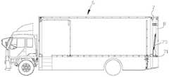
图2为车载检测设备的布局图;Fig. 2 is the layout diagram of vehicle-mounted detection equipment;
图3为柜门自动打开的装置结构示意图;Fig. 3 is a schematic structural diagram of the device for automatically opening the cabinet door;
图4为真空吸盘装置的结构示意图;Fig. 4 is the structural representation of vacuum chuck device;
图5为弹性连接柱的结构示意图;Fig. 5 is a structural schematic diagram of an elastic connecting column;
图6为开关柜检测车辆的机构示意图;Fig. 6 is a schematic diagram of the mechanism of the switchgear detecting the vehicle;
图7为车厢尾部的机构示意图;Fig. 7 is the schematic diagram of the mechanism at the rear of the compartment;
图8为图7中A部分的放大图;Fig. 8 is an enlarged view of part A in Fig. 7;
图9为图7中B部分的放大图;Fig. 9 is an enlarged view of part B in Fig. 7;
图10为汽车尾板的俯视示意图;Figure 10 is a top view schematic diagram of the tailgate of an automobile;
图11为图10中C部分的放大图;Figure 11 is an enlarged view of part C in Figure 10;
图12为汽车尾板打开的示意图;Fig. 12 is the schematic diagram that tailgate of automobile is opened;
图13为动力滚筒装置的结构示意图;Fig. 13 is a structural schematic diagram of a power drum device;
图14为动力滚筒装置的局部示意图1;Fig. 14 is a partial schematic view 1 of the power drum device;
图15为动力滚筒装置的局部示意图2。Fig. 15 is a partial schematic diagram 2 of the power drum device.
图16为检测旋转定位装置的结构示意图;Fig. 16 is a schematic structural diagram of a detection rotation positioning device;
图17为图16中D部分的局部放大图;Fig. 17 is a partially enlarged view of part D in Fig. 16;
图18为检测旋转定位装置的示意图;Fig. 18 is a schematic diagram of detecting the rotation positioning device;
图19为开关柜检测过程示意图。Fig. 19 is a schematic diagram of the detection process of the switchgear.
图20为同步顶升和展开装置原理图;Figure 20 is a schematic diagram of the synchronous jacking and deployment device;
图21为液压同步控制系统结构;Fig. 21 is the hydraulic synchronous control system structure;
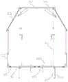
图22为可扩容车辆结构的开启结构示意图;Fig. 22 is a schematic diagram of the opening structure of the expandable vehicle structure;
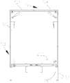
图23为行驶状态车辆示意图;Fig. 23 is a schematic diagram of a vehicle in a driving state;
图24为检验系统结构示意图。Fig. 24 is a schematic structural diagram of the inspection system.
具体实施方式Detailed ways
下面对本发明的具体实施方式作进一步说明。在此需要说明的是,对于这些实施方式的说明用于帮助理解本发明,但并不构成对本发明的限定。Specific embodiments of the present invention will be further described below. It should be noted here that the descriptions of these embodiments are used to help understand the present invention, but are not intended to limit the present invention.
如附图1~10所示,一种适用于车载开关柜机器人运行的检测机器人控制系统,包括总监控系统、和为总监控系统供电的UPS不间断电源系统;As shown in Figures 1 to 10, a detection robot control system suitable for vehicle-mounted switchgear robot operation, including a general monitoring system and a UPS uninterruptible power supply system for powering the general monitoring system;
总监控系统包括检验系统和机器人系统,检验系统和机器人系统之间经由信号互反馈的方式以保证开关柜自动传输到检测中心的系统运行和检测的精度;总监控系统控制伺服电机、液压缸、工业机器人和检测传感器工作。The total monitoring system includes the inspection system and the robot system. The signal feedback between the inspection system and the robot system ensures the system operation and detection accuracy of the automatic transmission of the switchgear to the inspection center; the total monitoring system controls the servo motor, hydraulic cylinder, Industrial robots and detection sensors work.
机器人系统包括:Robotic systems include:
(1)柜门自动打开装置,实现将开关柜的断路器格室和母线格室的柜门打开和关闭,以方便检验系统对开关柜的内外部检测;(1) The automatic opening device of the cabinet door realizes the opening and closing of the cabinet doors of the circuit breaker compartment and the busbar compartment of the switch cabinet, so as to facilitate the inspection system to detect the inside and outside of the switch cabinet;
(2)开关柜自动提升装置,实现开关柜的提升和降落,以及从汽车尾板输送到过渡滚筒装置;(2) The automatic lifting device of the switch cabinet realizes the lifting and lowering of the switch cabinet, and conveys from the tail plate of the car to the transition roller device;
(3)过渡滚筒装置,实现将开关柜从设有动力滚筒装置的汽车尾板传送到检测平台;(3) Transition roller device, which realizes the transfer of the switchgear from the tailgate of the vehicle equipped with the power roller device to the detection platform;
(4)旋转定位装置,实现开关柜的四周旋转以进行后续的扫描检验;(4) The rotating positioning device realizes the rotation of the switchgear around for subsequent scanning inspection;
(5)以及可扩容车辆结构,提供大尺寸开关柜或开关柜位于检测平台进行全周检测时,车厢内有足够容纳的空间。(5) As well as the expandable vehicle structure, when a large-size switchgear or a switchgear is located on the detection platform for full-circle detection, there is enough space in the compartment.
检验系统包括用于检测开关柜品质的检测传感器及其终端执行器构成。检验系统包括:The inspection system consists of detection sensors and terminal actuators used to detect the quality of switch cabinets. The inspection system includes:
(1)对开关柜综合性能进行检测的三维扫描检测系统及其终端执行器,(1) The three-dimensional scanning detection system and its terminal actuator for detecting the comprehensive performance of the switchgear,
(2)对开关柜二维码的拍摄扫描及其箱体检测的CCD检测系统及其终端执行器,(2) The CCD detection system for shooting and scanning the two-dimensional code of the switch cabinet and its box body detection and its terminal actuator,
(3)对开关柜母线表面的材质检测系统及其终端执行器。(3) The material detection system and its terminal actuator on the surface of the switchgear busbar.
柜门自动打开装置包括安装于车厢底板200上的水平移动导轨2和沿水平移动导轨2运动的水平移动滑块21、固定在水平移动滑块21上的垂直立柱导轨3和沿垂直立柱导轨3运动的垂直移动滑块31、安装在垂直移动滑块31上的工业机器人4,工业机器人4的操作端连接真空吸盘装置5;水平移动导轨2和垂直立柱导轨3上设有驱动滑块运动的伺服电机。The cabinet door automatic opening device comprises a horizontally moving
真空吸盘装置5包括连接法兰51、通过弹性连接柱52与连接法兰51连接真空吸盘53,弹性连接柱52的两端连接气管(未示出)和真空吸盘53。The
连接法兰51通过连接柱54与工业机器人4的操作端连接。The connecting
弹性连接柱52包括固定夹具521、导向轴522、套装在导向轴522的凸缘面上的压缩弹簧523,紧固螺栓通过固定夹具521将导向轴522连接在连接法兰51上;真空吸盘53通过球铰链531与导向轴522铰接;受到压力时,真空吸盘53沿着导向轴522伸缩运动。The elastic connecting
导向轴522和球铰链531的中空通孔连通,并分别与气管(未示出)和真空吸盘53连通。The
连接法兰51设有3个弹性连接柱52,弹性连接柱52之间圆周角为120°。The connecting
工业机器人4通过螺栓连接固定在垂直移动滑块31上,以限制机器人底座的垂直方向的运动。The
水平移动滑块21设置有滑块座、止动块、限位装置、斜撑梢。The horizontally moving
水平移动导轨2包括平行设置的第一水平移动导轨22和第二水平移动导轨23。The horizontal moving
工业机器人4包括四轴机器人、五轴机器人、六轴机器人。
根据基于真空吸盘的开关柜柜门自动打开的装置的打开方法,包括以下步骤:According to the opening method of the device for automatically opening the switch cabinet door based on the vacuum suction cup, the following steps are included:
S1.水平移动导轨2安装于底板1上,控制器(未示出)设定驱动器驱动水平移动滑块21,控制工业机器人4与垂直立柱导轨3水平方向的移动;S1. The horizontal moving
S2.垂直立柱导轨3与水平移动导轨滑块21连接,控制器设定驱动器驱动垂直移动滑块31,控制工业机器人4垂直方向的移动;S2. The vertical
S3.工业机器人4与垂直立柱导轨滑块31连接,工业机器人4按照设定的运动轨迹,控制工业机器人操作端及真空吸盘53运动到工作点;S3. The
S4.真空吸盘53与开关柜接触,由气管形成负压压力吸住开关柜柜门,再由工业机器人4的姿态变化控制柜门的打开或关闭。S4. The
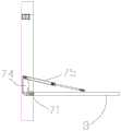
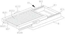
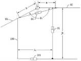
开关柜自动提升装置包括与车厢6刚性连接的液压缸组件7、通过旋转铰链71与液压缸组件铰接的汽车尾板8,以及设置在汽车尾板8上的动力滚筒装置81;The switchgear automatic lifting device includes a hydraulic cylinder assembly 7 rigidly connected to the compartment 6, an
动力滚筒装置81包括底部框架811,和设置在底部框架811上由动力驱动往返的动力滚筒组件812;The
动力滚筒组件812包括两台相对设置在边框8121上的伺服电机8122、以及一排两端活动设置在边框8121上的滚筒8123;The
液压缸组件7的缸筒竖直固定在车厢6尾部的立柱61上,活塞杆72的末端连接横梁73,驱动横梁73升降;横梁73上设有旋转铰链71与汽车尾板8铰接。The cylinder barrel of the hydraulic cylinder assembly 7 is vertically fixed on the
液压缸组件7的横梁上设有铰接支座74,铰接支座74上设有液压杆75,液压杆75的另一端与汽车尾板8铰接,驱动汽车尾板8的开合状态。The crossbeam of the hydraulic cylinder assembly 7 is provided with a hinged
底部框架811上设有伺服电机8122、和由伺服电机驱动的传动杆8126,传动杆8126上设有齿轮,动力滚筒组件812的边框上设有与齿轮啮合的齿条8127,由齿轮驱动动力滚筒组件往返运动。The
伺服电机8122通过减速器8128分别连接两个传动杆8126,动力滚筒组件812的左右边框上平行设有两个与传动杆的齿轮配合的齿条8127。The
传动杆8126的一端通过轴承安装于底部框架811上。One end of the
底部框架811两侧设有轴承滑道813,轴承滑道813由两排平行安装在底部框架811上轴承构成;动力滚筒组件812的底部设有与轴承滑道813相配合的工字型滑轨8129。Both sides of the
该开关柜自动提升装置的控制方法包括以下步骤:The control method of the switch cabinet automatic lifting device comprises the following steps:
S1.液压缸组件7与车厢6刚性连接,液压缸提供垂直方向的自由度,控制中心控制液压缸的活塞杆72垂直方向的运动;S1. The hydraulic cylinder assembly 7 is rigidly connected to the carriage 6, the hydraulic cylinder provides a degree of freedom in the vertical direction, and the control center controls the vertical movement of the
S2.汽车尾板8通过旋转铰链71与液压缸组件7铰接,旋转铰链71提供汽车尾板8转动方向的自由度,限制汽车尾板8的转动角度为0~90°,初始位置为水平状态;当液压缸组件7工作到指定位置时,开关柜被送入工作位置,同时汽车尾板8收起,此时汽车尾板的工作状态为垂直位置;S2. The
S3.动力滚筒装置81安装在汽车尾板8上,若干个滚筒依次排列,组成动力滚筒组;开关柜放置在动力滚筒装置81上,通过滚筒8123将开关柜送往工作位置;S3. The
S4.汽车尾板8初始状态与路面重合,将开关柜送至动力滚筒装置81后,液压缸组件7启动,将汽车尾板8及开关柜提升至指定位置,启动动力滚筒装置81将开关柜送往工作位置,同时汽车尾板8收起;当开关柜检测完毕,开启汽车尾板8,启动动力滚筒装置81将开关柜从工作位置送至汽车尾板8,启动液压缸组件7,汽车尾板8下降到地面,工作结束。S4. The initial state of the
旋转定位装置包括齿轮回转支承300、驱动齿轮回转支承300的伺服电机8122和减速机305、检测平台302,以及定位传感器303;The rotation positioning device includes a gear slewing bearing 300, a
检测平台302安装于齿轮回转支承300上,由伺服电机8122和减速机驱动齿轮回转支承300,带动检测平台302转动;The
定位传感器303分别检测平台的四个方位,通过分析的定位传感器303之间的相对坐标关系,实现检测平台302的定位;
检测平台302包括动力滚筒组件812;动力滚筒组件812包括两台相对设置在边框上的伺服电机8122、以及一排两端活动设置在边框上的滚筒8123;The
滚筒8123的两个端部设有齿轮,滚筒8123之间的齿轮相互啮合,滚筒8123的齿轮与伺服电机8122的齿轮啮合,由伺服电机8122驱动;The two ends of the
相邻滚筒8123之间的齿轮分别为与滚筒刚性连接和活动连接,实现所有滚筒8123有相同的转动方向。其中,活动连接为齿轮通过轴承安装在滚筒8123上。The gears between
齿轮回转支承300、伺服电机8122和减速机305设置于底座304上,底座304固定设置在车辆的车厢底板。The gear slewing bearing 300, the
伺服电机8122驱动减速机305,减速机305连接齿轮,齿轮与齿轮回转支承300的齿轮啮合。The
检测平台302通过底板306安装于齿轮回转支承300上,底板与齿轮回转支承300的内圈固定连接。The
滚筒8123的两端通过轴承平行设置与侧板上。The two ends of
伺服电机8122设置在边框的同一端部,并实现相同的转动方向。The
检测平台302具有4×90°四个旋转姿态,实现开关柜四个面的连续检测。The
本基于伺服驱动的车载开关柜检测机器人系统旋转定位装置使用时,其原理是:检测平台302下的齿轮回转支承300在伺服电机8122的带动下实现检测平台302的转动,检测平台302具有4×90°的转动姿态,依靠四个定位传感器303的相对坐标关系进行检测平台302的定位,从而确保检测平台302每个位置姿态的准确性。When the rotary positioning device of the vehicle-mounted switch cabinet detection robot system based on servo drive is used, its principle is: the
应用时:首先通过动力滚筒组件812自动调整将开关柜移动到待检测位置,供后期进行检测。In application: firstly, the switchgear is automatically adjusted by the
定位传感器303根据相对坐标关系发出检测平台302的定位信息,并进行开关柜1号侧面的检测,1号侧面检测完成后,伺服电机驱动检测平台302旋转90°,进行2号侧面检测,以此类推直到四个侧面全部完成检测。The
过渡滚筒600包括升降台、滚筒、伺服电机、轴承座、联轴器。The
升降台与车厢刚性连接,由伺服电机驱动升降;滚筒通过轴承座设置在边框上,由伺服电机驱动。The lifting platform is rigidly connected with the carriage, and is driven by a servo motor to lift; the roller is set on the frame through the bearing seat, and is driven by the servo motor.
过渡滚筒600包含升降台、滚筒、伺服电机、轴承座、联轴器。驱动器驱动伺服电机,由伺服电机传动控制升降台升降,提供滚筒垂直方向的自由度。The
当液压缸组件7工作到对接位置时,伺服电机驱动升降台工作到对接位置完成对接;当开关柜处于检测状态时,升降台下移以防止阻碍旋转检测平台的检测;检验完成,尾板放下并升降到与检验平台对接高渡位置,过渡滚筒平台上升。When the hydraulic cylinder assembly 7 works to the docking position, the servo motor drives the lifting table to work to the docking position to complete the docking; when the switchgear is in the detection state, the lifting table moves down to prevent the detection of the rotating detection platform; after the inspection is completed, the tailgate is put down And lift to the high crossing position docked with the inspection platform, and the transition roller platform rises.
可扩容车辆结构包括车厢顶板9、车厢侧板100和车厢底板200,车厢顶板9通过至少4个伸缩立柱91支撑,伸缩立柱91与车辆底架201固定连接;车厢侧板100呈“L”型,包括嵌套底板101和侧板102;车厢底板200安装在车辆底架201上,嵌套底板101与车厢底板200采用嵌套连接,通过侧板调整装置103控制嵌套底板101与车厢底板200间的嵌套距离调节车厢宽度;车厢顶板9包括车厢柱顶板92和两侧的翼板93,车厢柱顶板92和两侧的翼板93铰接,并设有翼板调整装置94来调节翼板93张开幅度;The expandable vehicle structure includes a compartment roof 9, a
伸缩立柱91、侧板调整装置103、翼板调整装置94为液压驱动,通过液压同步系统实现车厢的同步顶升和展开;The
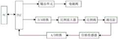
液压同步系统采用PLC控制,PLC输出液压缸的控制参数经D/A转换、比例放大器后传输给比例阀,比例阀通过调控液压阀流量控制液压缸的移动速度,位移传感器采集各液压缸位移信息并反馈给PLC,从而实现液压同步系统的闭环控制。The hydraulic synchronization system adopts PLC control. The control parameters of the hydraulic cylinder output by the PLC are transmitted to the proportional valve after D/A conversion and proportional amplifier. The proportional valve controls the moving speed of the hydraulic cylinder by regulating the flow of the hydraulic valve, and the displacement sensor collects the displacement information of each hydraulic cylinder. And feedback to PLC, so as to realize the closed-loop control of the hydraulic synchronous system.
本用于开关柜检测的车厢同步顶升和展开装置使用时,其原理是:如图1所示,车厢顶板9与伸缩立柱91上端固接,通过伸缩立柱91实现车厢顶板9的支撑及高度方向的调整。车厢侧板100底部嵌套在车厢底板200内并与车厢底板200内的侧板调整装置103连接,通过侧板调整装置103进行车厢宽度方向的调整。车厢顶板9上的两侧翼板93通过翼板调整装置94展开,使翼板93始终与车厢侧板100保持搭接。伸缩立柱91、侧板调整装置103和翼板调整装置94均为液压驱动,在液压同步控制系统的控制下,调控各液压缸的流量,确保车厢同步顶升和展开的同时,保证翼板张开幅度与顶升、展开尺寸相匹配。When the compartment synchronous jacking and unfolding device used for switchgear detection is used, its principle is: as shown in Figure 1, the compartment roof 9 is fixedly connected to the upper end of the
工作时,如图2所示,计算机根据各液压缸的伸缩速度,通过PLC输出液压缸的控制参数,输出的控制参数经D/A转换、比例放大器后传输给比例阀,比例阀通过调控液压阀流量来控制液压缸的移动速度实现车厢扩容,同时通过位移传感器采集各液压缸位移信息并反馈给PLC进行实时调控。When working, as shown in Figure 2, the computer outputs the control parameters of the hydraulic cylinders through the PLC according to the expansion and contraction speed of each hydraulic cylinder, and the output control parameters are transmitted to the proportional valve after D/A conversion and proportional amplifier. The valve flow rate is used to control the moving speed of the hydraulic cylinder to realize the expansion of the carriage. At the same time, the displacement information of each hydraulic cylinder is collected through the displacement sensor and fed back to the PLC for real-time regulation.
伸缩立柱91包括一组相互嵌套的立柱外壳和设置在立柱外壳内的液压缸95,液压缸95的一端与车厢顶板9连接,另一端与车辆底架201连接。The
车厢底板200为双层中空结构,嵌套底板101嵌套于双层中空结构中。The
侧板调整装置103为液压缸,液压缸的缸体与车厢底板固定连接,活塞杆104与嵌套底板101连接,驱动嵌套底板101运动。The side
车厢侧板100侧面呈阶梯型,并与翼板93相配合;行车时,翼板93与车厢侧板100拼接为一体;扩容过程,翼板93始终搭接在车厢侧板100上。The side of the
车辆底架201上设有至少4个用于支撑车辆以及调整车厢底板水平度的车辆支撑机构202。车辆支撑机构202包括设置液压油缸的支撑腿。The
用于开关柜检测的车厢同步顶升和展开系统还包括水平检测仪表(未示出)。The compartment synchronous jacking and unfolding system for switchgear detection also includes a level detection instrument (not shown).
终端执行器包括实现3个垂直方向和1个旋转方向运动的四自由度移动平台、工业机器人4和安装于工业机器人操作端的检测传感器;The terminal effector includes a four-degree-of-freedom mobile platform that can move in three vertical directions and one rotational direction, an
四自由度移动平台包括平行设置的第三水平移动导轨24和第四水平移动导轨25构成纵向水平直线导轨;The four-degree-of-freedom mobile platform includes a third horizontally
第三水平移动导轨24和第四水平移动导轨25上的滑块设有横向水平移动导轨26;The slide block on the third horizontally moving
垂直立柱导轨3通过旋转气缸32与横向水平移动导轨26上的水平移动滑块21连接;The vertical
工业机器人4安装在垂直立柱导轨3的垂直移动滑块上31。The
汽车车厢底板200上还设有三维空间跟踪定位器500。A three-dimensional
以上对本发明的实施方式作了详细说明,但本发明不限于所描述的实施方式。对于本领域的技术人员而言,在不脱离本发明原理和精神的情况下,对这些实施方式进行多种变化、修改、替换和变型,仍落入本发明的保护范围内。The embodiments of the present invention have been described in detail above, but the present invention is not limited to the described embodiments. For those skilled in the art, without departing from the principle and spirit of the present invention, various changes, modifications, substitutions and modifications to these embodiments still fall within the protection scope of the present invention.
Claims (8)
Priority Applications (1)
| Application Number | Priority Date | Filing Date | Title |
|---|---|---|---|
| CN202110093674.0ACN113146646B (en) | 2021-01-22 | 2021-01-22 | A detection robot control system suitable for vehicle-mounted switchgear robot operation |
Applications Claiming Priority (1)
| Application Number | Priority Date | Filing Date | Title |
|---|---|---|---|
| CN202110093674.0ACN113146646B (en) | 2021-01-22 | 2021-01-22 | A detection robot control system suitable for vehicle-mounted switchgear robot operation |
Publications (2)
| Publication Number | Publication Date |
|---|---|
| CN113146646A CN113146646A (en) | 2021-07-23 |
| CN113146646Btrue CN113146646B (en) | 2023-03-07 |
Family
ID=76879240
Family Applications (1)
| Application Number | Title | Priority Date | Filing Date |
|---|---|---|---|
| CN202110093674.0AActiveCN113146646B (en) | 2021-01-22 | 2021-01-22 | A detection robot control system suitable for vehicle-mounted switchgear robot operation |
Country Status (1)
| Country | Link |
|---|---|
| CN (1) | CN113146646B (en) |
Families Citing this family (5)
| Publication number | Priority date | Publication date | Assignee | Title |
|---|---|---|---|---|
| CN113555963B (en)* | 2021-07-28 | 2023-12-12 | 西安今盛实业有限公司 | Mobile intelligent power linkage operation method |
| CN114955927B (en)* | 2022-05-18 | 2023-12-12 | 广东电网能源发展有限公司 | Power equipment transfer assembly and power equipment transfer method |
| CN114696252B (en)* | 2022-06-01 | 2022-08-16 | 杭州勒格智能设备有限公司 | Transformer overhauls detection robot |
| CN116119268B (en)* | 2022-09-02 | 2025-08-15 | 广东电网有限责任公司广州供电局 | Guide rail type mobile robot for carrying switch cabinet movement |
| CN115871001B (en)* | 2023-03-08 | 2023-05-16 | 江苏环亚医用科技集团股份有限公司 | Hydraulic operating arm for medical robot |
Citations (10)
| Publication number | Priority date | Publication date | Assignee | Title |
|---|---|---|---|---|
| CN202986934U (en)* | 2012-09-28 | 2013-06-12 | 广东信源物流设备有限公司 | Two side double-layer double-transfiguration type display car |
| CN203078390U (en)* | 2013-01-31 | 2013-07-24 | 山东电力集团公司电力科学研究院 | Vehicle-mounted integrated electrical equipment quality detecting platform |
| CN207257481U (en)* | 2017-04-19 | 2018-04-20 | 国网电力科学研究院武汉南瑞有限责任公司 | A kind of wing opens expansion partial discharge pressure test car |
| CN208291061U (en)* | 2018-06-21 | 2018-12-28 | 东莞市巨人机械设备制造有限公司 | A kind of Lifting tail gate with gap bridge motor track |
| CN109927045A (en)* | 2019-03-15 | 2019-06-25 | 徐秀荣 | A kind of power distribution cabinet crusing robot |
| CN110131961A (en)* | 2019-06-11 | 2019-08-16 | 青岛诺金自动化装备有限公司 | A kind of retail units with automatic door-opening mechanism |
| CN210619235U (en)* | 2019-08-03 | 2020-05-26 | 广东智源机器人科技有限公司 | A conveying mechanism and food steamer machine for food steamer machine |
| CN211809263U (en)* | 2020-03-30 | 2020-10-30 | 湖北九霖机械装备有限公司 | Tailboard for truck |
| CN111960084A (en)* | 2020-09-18 | 2020-11-20 | 浙江万家工业设备有限公司 | Rotating disc type power roller and butt joint device |
| CN112123368A (en)* | 2020-09-04 | 2020-12-25 | 国网宁夏电力有限公司检修公司 | A mechanical arm structure and detection robot |
Family Cites Families (1)
| Publication number | Priority date | Publication date | Assignee | Title |
|---|---|---|---|---|
| US7967543B2 (en)* | 2007-05-23 | 2011-06-28 | Wynright Corporation | Automatic case loader and method for use of same |
- 2021
- 2021-01-22CNCN202110093674.0Apatent/CN113146646B/enactiveActive
Patent Citations (10)
| Publication number | Priority date | Publication date | Assignee | Title |
|---|---|---|---|---|
| CN202986934U (en)* | 2012-09-28 | 2013-06-12 | 广东信源物流设备有限公司 | Two side double-layer double-transfiguration type display car |
| CN203078390U (en)* | 2013-01-31 | 2013-07-24 | 山东电力集团公司电力科学研究院 | Vehicle-mounted integrated electrical equipment quality detecting platform |
| CN207257481U (en)* | 2017-04-19 | 2018-04-20 | 国网电力科学研究院武汉南瑞有限责任公司 | A kind of wing opens expansion partial discharge pressure test car |
| CN208291061U (en)* | 2018-06-21 | 2018-12-28 | 东莞市巨人机械设备制造有限公司 | A kind of Lifting tail gate with gap bridge motor track |
| CN109927045A (en)* | 2019-03-15 | 2019-06-25 | 徐秀荣 | A kind of power distribution cabinet crusing robot |
| CN110131961A (en)* | 2019-06-11 | 2019-08-16 | 青岛诺金自动化装备有限公司 | A kind of retail units with automatic door-opening mechanism |
| CN210619235U (en)* | 2019-08-03 | 2020-05-26 | 广东智源机器人科技有限公司 | A conveying mechanism and food steamer machine for food steamer machine |
| CN211809263U (en)* | 2020-03-30 | 2020-10-30 | 湖北九霖机械装备有限公司 | Tailboard for truck |
| CN112123368A (en)* | 2020-09-04 | 2020-12-25 | 国网宁夏电力有限公司检修公司 | A mechanical arm structure and detection robot |
| CN111960084A (en)* | 2020-09-18 | 2020-11-20 | 浙江万家工业设备有限公司 | Rotating disc type power roller and butt joint device |
Also Published As
| Publication number | Publication date |
|---|---|
| CN113146646A (en) | 2021-07-23 |
Similar Documents
| Publication | Publication Date | Title |
|---|---|---|
| CN113146646B (en) | A detection robot control system suitable for vehicle-mounted switchgear robot operation | |
| CN105945900B (en) | Crusing robot in a kind of transformer station room | |
| WO2019134511A1 (en) | Manipulation robot for assembly test operations of space station experiment cabinet | |
| CN110900481A (en) | Flexible array aircraft skin adsorbs frock | |
| CN102601120A (en) | Automatic roll changing and adjusting device of rolling mill and operation method of automatic roll changing and adjusting device | |
| CN210475953U (en) | Movable gantry platform structure of ship welding robot | |
| CN104709474B (en) | A kind of high-accuracy vertical butt joint system of Large Spacecraft | |
| CN202539195U (en) | Automatic roll changing and adjusting device of mill | |
| WO2019111522A1 (en) | Surface processing system for large object | |
| CN202574633U (en) | Large high-precision large-inertia rotating and assembling mechanical arm system | |
| CN110509311A (en) | Light-load multi-redundant drive six-degree-of-freedom parallel attitude-adjusting platform based on three legs | |
| CN202471621U (en) | Multi-shaft motion mechanical arm of X-ray digital panel imaging detection system | |
| CN112936297A (en) | Robot system for automatically detecting vehicle-mounted switch cabinet | |
| CN115931374A (en) | Automatic detection device is synthesized to navigation car | |
| CN112917491B (en) | System and method for automatically transferring switch cabinet to detection center | |
| CN205685324U (en) | A kind of gantry truss-like indoor substation crusing robot | |
| CN112834512A (en) | A Robot System Using CCD to Complete the Quality Inspection of Switchgear | |
| CN112693527B (en) | A cabin synchronous jacking and unfolding system for switch cabinet detection | |
| CN115520230B (en) | False trolley and locomotive body steel structure assembly process | |
| CN217018703U (en) | Mechanical arm type auxiliary rapid hole making tool based on electrical control system | |
| CN116544828A (en) | Inspection equipment for power distribution station and inspection method thereof | |
| CN112787259B (en) | Vehicle-mounted switch cabinet detection rotary positioning device based on servo drive | |
| CN214724215U (en) | Six-axis column coordinate industrial robot | |
| CN115676622A (en) | Accurate positioning auxiliary adjusting method for rotary crane gate | |
| CN113147555B (en) | Device for transferring switch cabinet from automobile tail plate to rotary table by automatic lifting structure |
Legal Events
| Date | Code | Title | Description |
|---|---|---|---|
| PB01 | Publication | ||
| PB01 | Publication | ||
| SE01 | Entry into force of request for substantive examination | ||
| SE01 | Entry into force of request for substantive examination | ||
| GR01 | Patent grant | ||
| GR01 | Patent grant |