CN113146579B - A cross-joint load-bearing support device based on passive variable stiffness damper - Google Patents
A cross-joint load-bearing support device based on passive variable stiffness damperDownload PDFInfo
- Publication number
- CN113146579B CN113146579BCN202110425447.3ACN202110425447ACN113146579BCN 113146579 BCN113146579 BCN 113146579BCN 202110425447 ACN202110425447 ACN 202110425447ACN 113146579 BCN113146579 BCN 113146579B
- Authority
- CN
- China
- Prior art keywords
- variable stiffness
- plate
- stiffness damper
- load
- damper
- Prior art date
- Legal status (The legal status is an assumption and is not a legal conclusion. Google has not performed a legal analysis and makes no representation as to the accuracy of the status listed.)
- Active
Links
- 230000007246mechanismEffects0.000claimsabstractdescription105
- 210000003423ankleAnatomy0.000claimsdescription31
- 210000002683footAnatomy0.000claimsdescription16
- 210000003141lower extremityAnatomy0.000claimsdescription11
- 229920001971elastomerPolymers0.000claimsdescription8
- 230000005021gaitEffects0.000claimsdescription6
- 230000003014reinforcing effectEffects0.000claimsdescription4
- 238000009434installationMethods0.000claimsdescription3
- 238000013016dampingMethods0.000abstractdescription10
- 230000008859changeEffects0.000abstractdescription8
- 230000001960triggered effectEffects0.000abstractdescription3
- 230000003044adaptive effectEffects0.000abstractdescription2
- 239000000463materialSubstances0.000description9
- 230000002787reinforcementEffects0.000description6
- 238000010586diagramMethods0.000description5
- 239000000806elastomerSubstances0.000description4
- 210000000544articulatio talocruralisAnatomy0.000description3
- 230000002503metabolic effectEffects0.000description3
- 230000009471actionEffects0.000description2
- 230000008901benefitEffects0.000description2
- 230000037396body weightEffects0.000description2
- 238000013461designMethods0.000description2
- 230000006872improvementEffects0.000description2
- 210000001503jointAnatomy0.000description2
- 238000000034methodMethods0.000description2
- 238000011160researchMethods0.000description2
- 238000012546transferMethods0.000description2
- 208000031638Body WeightDiseases0.000description1
- 230000000386athletic effectEffects0.000description1
- 230000009286beneficial effectEffects0.000description1
- 238000006243chemical reactionMethods0.000description1
- 125000004122cyclic groupChemical group0.000description1
- 230000007423decreaseEffects0.000description1
- 230000007547defectEffects0.000description1
- 230000007123defenseEffects0.000description1
- 238000006073displacement reactionMethods0.000description1
- 230000000694effectsEffects0.000description1
- 238000005265energy consumptionMethods0.000description1
- 238000005516engineering processMethods0.000description1
- 230000002708enhancing effectEffects0.000description1
- 210000003414extremityAnatomy0.000description1
- 230000005484gravityEffects0.000description1
- 210000001624hipAnatomy0.000description1
- 210000004394hip jointAnatomy0.000description1
- 210000003127kneeAnatomy0.000description1
- 210000000629knee jointAnatomy0.000description1
- 230000004048modificationEffects0.000description1
- 238000012986modificationMethods0.000description1
- 230000002232neuromuscularEffects0.000description1
- 238000005381potential energyMethods0.000description1
- 230000008569processEffects0.000description1
- 230000009467reductionEffects0.000description1
- 238000010008shearingMethods0.000description1
- 230000008719thickeningEffects0.000description1
- 230000009466transformationEffects0.000description1
Images


Classifications
- B—PERFORMING OPERATIONS; TRANSPORTING
- B25—HAND TOOLS; PORTABLE POWER-DRIVEN TOOLS; MANIPULATORS
- B25J—MANIPULATORS; CHAMBERS PROVIDED WITH MANIPULATION DEVICES
- B25J9/00—Programme-controlled manipulators
- B25J9/0006—Exoskeletons, i.e. resembling a human figure
Landscapes
- Engineering & Computer Science (AREA)
- Robotics (AREA)
- Mechanical Engineering (AREA)
- Rehabilitation Tools (AREA)
Abstract
Translated fromChinese
Description
Translated fromChinese技术领域technical field
本发明属于辅助负重设备相关技术领域,更具体地,涉及一种基于被动变刚度阻尼器的跨关节负重支撑装置。The invention belongs to the technical field of auxiliary load-bearing equipment, and more particularly relates to a cross-joint load-bearing support device based on passive variable stiffness dampers.
背景技术Background technique
人体负重外骨骼装置是一种能够增强人体负重运动能力、便携能力、机动能力、降低代谢能耗的外骨骼机器人技术装备,在军事、救灾、军事等方面得到了广泛应用。在军事方面,由于地形的复杂性,大规模机械化车辆难以深入到深林、山路、阶梯路面等地进行快速移动,而负重外骨骼这种既拥有人的智慧又能承受重载的机器,可以很大程度地提高部队的作战能力。在灾难救援中,一方面救援人员可以通过这种装置背负大量的消防器材到现场,另一方面可以不费太多力气地将受灾物资和人员转移到安全地点。在日常生活领域,外骨骼机器人可以辅助工人操作重型器械,降低肌骨劳损,减轻疲劳,提高工人的操作效率和定位精度。鉴于增强人体运动能力的外骨骼机器人对改善民众生活质量和提升国防军事力量的重要应用价值,世界各国政府均给予了高度的关注。The human body weight-bearing exoskeleton device is a kind of exoskeleton robot technology equipment that can enhance the human body's weight-bearing exercise ability, portability, maneuverability, and reduce metabolic energy consumption. It has been widely used in military, disaster relief, military and other fields. In the military aspect, due to the complexity of the terrain, it is difficult for large-scale mechanized vehicles to go deep into deep forests, mountain roads, stepped roads, etc. to move quickly, and the heavy-duty exoskeleton, a machine that has both human intelligence and can withstand heavy loads, can be very Greatly improve the combat capability of the troops. In disaster rescue, on the one hand, rescuers can carry a large amount of fire-fighting equipment to the scene through this device, and on the other hand, they can transfer the disaster-affected materials and personnel to a safe place without much effort. In the field of daily life, exoskeleton robots can assist workers to operate heavy equipment, reduce musculoskeletal strain, reduce fatigue, and improve workers' operating efficiency and positioning accuracy. In view of the important application value of exoskeleton robots that enhance human movement ability to improve people's quality of life and enhance national defense and military strength, governments around the world have paid great attention.
近二十年来,很多科研机构在穿戴式下肢外骨骼领域开展了广泛的研究,研发了多款有重要科学意义的下肢外骨骼装置。按照是否包含外部能量源、下肢外骨骼一部分为主动外骨骼和被动外骨骼,主动外骨骼装置通常包含执行机构、传感器、控制模块以及配套的外部驱动电源等,质量普遍较大。穿戴式下肢主动外骨骼装置借助多种不同的传感器模块,以获取穿戴者的运动意图,再通过控制系统主动调控各个执行机构的输出力和力矩,使得外骨骼匹配穿戴者的运动,进而增强穿戴者的运动能力。下肢被动外骨骼装置基于人体下肢运动规律,利用肢体与外部弹性元件之间动能和势能的循环转化,借助外部被动弹性元件以辅助人体下肢运动。下肢被动外骨骼装置通常具有重量轻、结构简单等特点,通过合理布置外部弹性元件、设计恰当被动释能调节装置,被动外骨骼可以在人体运动过程中很好地匹配下肢运动学规律以及肌骨系统内在的能量转换机理,进而减少代谢能的消耗。因此,相对于质量较大、结构复杂、与穿戴者行动意图配合困难的主动外骨骼而言,被动外骨骼在提升人体运动能力、减少所消耗的代谢能方面具有潜在优势。目前大多数被动式外骨骼不能承载负载,而少量的被动式外骨骼为准被动式,仍然存在动力能源限制的问题。In the past two decades, many scientific research institutions have carried out extensive research in the field of wearable lower extremity exoskeletons, and developed a variety of lower extremity exoskeleton devices with important scientific significance. Depending on whether an external energy source is included, and a part of the lower extremity exoskeleton is an active exoskeleton and a passive exoskeleton, an active exoskeleton device usually includes an actuator, a sensor, a control module, and a supporting external drive power supply, etc., and the quality is generally large. The wearable lower limb active exoskeleton device uses a variety of different sensor modules to obtain the wearer's movement intention, and then actively regulates the output force and torque of each actuator through the control system, so that the exoskeleton matches the wearer's movement, thereby enhancing the wearability. the athletic ability of the person. The lower limb passive exoskeleton device is based on the motion law of the lower limbs of the human body, utilizes the cyclic transformation of kinetic energy and potential energy between the limbs and the external elastic elements, and assists the movement of the lower limbs of the human body with the help of the external passive elastic elements. Passive lower extremity exoskeleton devices usually have the characteristics of light weight and simple structure. By rationally arranging external elastic elements and designing appropriate passive energy release adjustment devices, passive exoskeletons can well match the kinematics of lower extremities and the musculoskeletal laws during human movement. The internal energy conversion mechanism of the system, thereby reducing the consumption of metabolic energy. Therefore, compared with active exoskeletons with large mass, complex structure, and difficulty in coordinating with the wearer's action intentions, passive exoskeletons have potential advantages in improving human exercise capacity and reducing the consumption of metabolic energy. At present, most passive exoskeletons cannot carry loads, while a small number of passive exoskeletons are quasi-passive and still have the problem of power energy limitation.
发明内容SUMMARY OF THE INVENTION
针对现有技术的以上缺陷或改进需求,本发明提供了一种基于被动变刚度阻尼器的跨关节负重支撑装置,所述支撑装置采用基于剪切增稠弹性体材料的智能变刚度阻尼器,在受到冲击或者剪切时可以实现被动自适应刚度,且通过人体运动被动触发阻尼器变刚度和变阻尼,不存在主动式负重外骨骼结构复杂及整机质量大的问题,解决了动力能源限制及需要进行人体运动意图的识别与匹配等问题。In view of the above defects or improvement needs of the prior art, the present invention provides a cross-joint load-bearing support device based on a passive variable stiffness damper, and the support device adopts an intelligent variable stiffness damper based on a shear-thickening elastomer material, Passive adaptive stiffness can be achieved when subjected to impact or shearing, and the damper can be passively triggered to change stiffness and damping through human motion. There is no active load-bearing exoskeleton with complex structure and large overall weight, which solves the limitation of power energy. And the recognition and matching of human motion intentions are required.
为实现上述目的,按照本发明的一个方面,提供了一种基于被动变刚度阻尼器的跨关节负重支撑装置,所述支撑装置包括负载支撑机构、离合器机构及变刚度阻尼器机构,所述离合器机构及所述变刚度阻尼器机构分别设置在所述负载支撑机构上,且所述离合器机构与所述变刚度阻尼器机构相连接;In order to achieve the above object, according to one aspect of the present invention, a cross-joint load bearing support device based on a passive variable stiffness damper is provided, the support device includes a load support mechanism, a clutch mechanism and a variable stiffness damper mechanism, the clutch The mechanism and the variable stiffness damper mechanism are respectively arranged on the load supporting mechanism, and the clutch mechanism is connected with the variable stiffness damper mechanism;
所述支撑装置为纯被动式下肢外骨骼,其通过人体运动来被动式触发所述离合器机构的开启及关闭,进而使得所述变刚度阻尼器机构分时锁定及释放。The support device is a pure passive lower extremity exoskeleton, which passively triggers the opening and closing of the clutch mechanism through the movement of the human body, thereby enabling the variable stiffness damper mechanism to be locked and released in a time-sharing manner.
进一步地,所述变刚度阻尼器机构包括阻尼器、上三角板及下三角板,所述上三角板的一端与所述负载支撑机构转动连接,另一端与所述下三角板的一端转动连接;所述下三角板的另一端与所述离合器机构转动连接;所述阻尼器的两端分别可拆卸地连接于所述上三角板及所述下三角板。Further, the variable stiffness damper mechanism includes a damper, an upper triangle plate and a lower triangle plate, one end of the upper triangle plate is rotatably connected with the load support mechanism, and the other end is rotatably connected with one end of the lower triangle plate; The other end of the triangular plate is rotatably connected with the clutch mechanism; the two ends of the damper are respectively detachably connected to the upper triangular plate and the lower triangular plate.
进一步地,所述阻尼器在所述上三角板及所述下三角板上的安装位置均能够调节。Further, the installation positions of the damper on the upper triangle plate and the lower triangle plate can be adjusted.
进一步地,所述支撑装置处于步骤周期0点时,所述离合器机构处于关闭状态,且所述变刚度阻尼器机构处于锁定状态,所述支撑装置承载的负重通过所述负载支撑机构传递到地面;所述支撑装置处于步态周期40%点时,即脚后跟离地时,所述离合器机构进入打开状态,且所述变刚度阻尼器机构被释放,所述变刚度阻尼器机构随人体自由摆动。Further, when the support device is at 0 o'clock in the step cycle, the clutch mechanism is in a closed state, and the variable stiffness damper mechanism is in a locked state, and the load carried by the support device is transmitted to the ground through the load support mechanism ; When the support device is at the 40% point of the gait cycle, that is, when the heel is off the ground, the clutch mechanism enters the open state, and the variable stiffness damper mechanism is released, and the variable stiffness damper mechanism swings freely with the human body .
进一步地,所述离合器机构能沿所述负载支撑机构做往复直线运动,且同时压缩所述变刚度阻尼器机构或者释放所述变刚度阻尼器机构;所述离合器机构包括齿轮齿条组件、触地杆、空间连接件及滑块组件,所述触地杆活动地连接于所述负载支撑机构,所述滑块组件包括设置在所述负载支撑机构上的直线导轨及滑动地设置在所述直线导轨上的滑块;所述齿轮齿条机构包括两个设置在所述负载支撑机构上且同轴设置的外齿轮及内齿轮、以及与所述外齿轮可分离地相啮合的第一齿条及与所述内齿轮相啮合的第二齿条,所述第一齿条及所述第二齿条分别与所述触地杆及所述空间连接件的一端相连接,所述空间连接件的另一端连接于所述滑块组件。Further, the clutch mechanism can perform reciprocating linear motion along the load supporting mechanism, and at the same time compress the variable stiffness damper mechanism or release the variable stiffness damper mechanism; the clutch mechanism includes a rack and pinion assembly, a contact A ground rod, a space connecting piece and a slider assembly, the ground rod is movably connected to the load support mechanism, the slider assembly includes a linear guide rail arranged on the load support mechanism and a linear guide rail slidably arranged on the load support mechanism A slider on a linear guide rail; the rack and pinion mechanism includes two external gears and an internal gear that are coaxially arranged on the load supporting mechanism, and a first tooth detachably meshed with the external gear A rack and a second rack meshing with the internal gear, the first rack and the second rack are respectively connected with the ground contact rod and one end of the space connecting piece, the space connecting The other end of the piece is connected to the slider assembly.
进一步地,所述负载支撑机构包括相连接的上部组件及下部组件,所述上部组件包括背包固定板、万向节、长度调节杆、上横板、上侧板、侧板加强肋及下横板,所述背包固定板用于承载背包,所述背包用于收容负载;两个所述万向节的一端转动地连接于所述背包固定板的两端,另一端分别连接于两个所述长度调节杆的一端,所述长度调节杆的另一端连接于所述上横板的中部;其中,所述长度调节杆的长度能调节;Further, the load supporting mechanism includes a connected upper assembly and a lower assembly, and the upper assembly includes a backpack fixing plate, a universal joint, a length adjustment rod, an upper transverse plate, an upper side plate, a side plate reinforcing rib and a lower transverse plate. Plate, the backpack fixing plate is used to carry the backpack, and the backpack is used to accommodate the load; one end of the two universal joints is rotatably connected to the two ends of the backpack fixing plate, and the other ends are respectively connected to the two One end of the length adjustment rod, and the other end of the length adjustment rod is connected to the middle part of the upper horizontal plate; wherein, the length of the length adjustment rod can be adjusted;
所述下横板与所述上横板间隔设置,四个所述上侧板两两为一组,每组所述上侧板的两端分别连接所述上横板及所述下横板,且每组的两个所述上侧板间隔设置并由一个所述侧板加强肋相连接,所述侧板加强肋邻近所述下横板设置。The lower transverse plate and the upper transverse plate are arranged at intervals, and four upper side plates are formed in pairs, and two ends of each group of the upper side plates are respectively connected to the upper transverse plate and the lower transverse plate , and the two upper side plates of each group are arranged at intervals and connected by one of the side plate reinforcement ribs, and the side plate reinforcement ribs are arranged adjacent to the lower transverse plate.
进一步地,所述下横板包括凹字形件及两个连接件,两个所述连接件分别活动地连接于所述凹字形件的两端;所述上侧板连接于所述凹字形件;其中,所述触地杆的一端活动地连接于一个所述连接件,其能相对于所述连接件移动。Further, the lower horizontal plate includes a concave-shaped piece and two connecting pieces, and the two connecting pieces are respectively movably connected to both ends of the concave-shaped piece; the upper side plate is connected to the concave-shaped piece. ; wherein, one end of the grounding rod is movably connected to one of the connecting pieces, which can move relative to the connecting pieces.
进一步地,所述下部组件包括外侧板、外侧杆、内侧杆、脚踝架及鞋子固定组件,所述内侧杆及所述外侧杆的一端依次分别穿过两个所述连接件后活动地连接于所述凹字形件的两端,另一端分别连接于U型的所述脚踝架的两端;两个所述外侧板的一端分别连接于两个所述连接件,另一端分别连接于所述脚踝架的两端;所述触地杆的另一端连接有万向球,其能相对于所述连接件做直线运动。Further, the lower assembly includes an outer plate, an outer rod, an inner rod, an ankle support and a shoe fixing assembly, and one ends of the inner rod and the outer rod pass through the two connecting pieces in turn and are movably connected to the two connecting pieces. The two ends of the concave-shaped piece and the other end are respectively connected to the two ends of the U-shaped ankle support; Two ends of the ankle frame; the other end of the grounding rod is connected with a universal ball, which can perform linear movement relative to the connecting piece.
进一步地,所述外齿轮及所述内齿轮分别设置在邻近所述触地杆的外侧板上,所述直线导轨设置在另一个所述外侧板朝向所述齿轮齿条机构的一侧上;所述鞋子固定组件连接于所述脚踝架。Further, the external gear and the internal gear are respectively arranged on the outer side plate adjacent to the ground contact rod, and the linear guide rail is arranged on the side of the other outer side plate facing the rack and pinion mechanism; The shoe securing assembly is connected to the ankle brace.
进一步地,所述鞋子固定组件包括第一踝轴、脚架连接件、第二踝轴、U型脚架、基板连接脚架及基板,所述第一踝轴的两端分别转动地连接于所述脚踝架及所述脚架连接件的一端,所述脚架连接件的另一端通过所述第二踝轴转动地连接于所述U型脚架,所述U型脚架的两端分别连接有基板连接脚架,所述基板连接脚架远离所述脚踝架的一端连接有基板,所述基板用于与鞋子的橡胶底相连接。Further, the shoe fixing assembly includes a first ankle shaft, a tripod connecting piece, a second ankle shaft, a U-shaped tripod, a base plate connecting tripod and a base plate, and two ends of the first ankle shaft are respectively rotatably connected to the base. The ankle bracket and one end of the tripod connector, the other end of the tripod connector is rotatably connected to the U-shaped tripod through the second ankle shaft, and the two ends of the U-shaped tripod are rotatably connected to the U-shaped tripod. A base plate connecting foot frame is respectively connected, and one end of the base plate connecting foot frame away from the ankle frame is connected with a base plate, and the base plate is used for connecting with the rubber sole of the shoe.
总体而言,通过本发明所构思的以上技术方案与现有技术相比,本发明提供的基于被动变刚度阻尼器的跨关节负重支撑装置主要具有以下有益效果:In general, compared with the prior art, the cross-joint load-bearing support device based on the passive variable stiffness damper provided by the present invention mainly has the following beneficial effects:
1.所述支撑装置为纯被动式外骨骼,其通过人体运动来被动触发阻尼器变刚度和变阻尼,可以在无能源驱动的被动条件下实现根据外部负载和足底冲击力的大小和速度来实现自适应变刚度及变阻尼,无需能源、传感器等,装置整体结构简单可靠,质量较轻。1. The support device is a pure passive exoskeleton, which passively triggers the damper to change stiffness and damping through human movement, and can realize the change of stiffness and damping according to the size and speed of the external load and the impact force of the foot under the passive condition of no energy drive. The self-adaptive variable stiffness and variable damping are realized without energy, sensors, etc. The overall structure of the device is simple and reliable, and the weight is light.
2.所述支撑装置通过离合机构实现支撑相“刚度足够”、摆动相“柔性充足”这一对不同的功能需求,该支撑装置在人体支撑相相对负载提供支撑,在摆动相不干扰人体的正常行走,跟随人体自由摆动。2. The supporting device realizes the different functional requirements of “sufficient rigidity” in the supporting phase and “sufficient flexibility” in the swinging phase through the clutch mechanism. Walk normally and swing freely with the human body.
3.所述阻尼器与上下三角板的连接位置可调,如此可以调整阻尼器的变刚度范围,可以满足不同环境和穿戴者的需求,适用范围广泛,还可以更换不同型号的剪切增稠弹性体材料,满足不同工况。3. The connection position of the damper and the upper and lower triangular plates can be adjusted, so that the variable stiffness range of the damper can be adjusted, which can meet the needs of different environments and wearers, and has a wide range of applications. It can also replace different types of shear thickening elasticity Body material to meet different working conditions.
4.所述支撑装置为非拟人结构,其无髋、膝、踝串联的关节机构,跨关节的结构设计方案可以使得负载重力通过支撑结构直接向地面传递,避免了为实现人-机运动匹配而不得不设计复杂的机械关节来匹配人体生物关节的问题。4. The support device is a non-anthropomorphic structure, it has no joint mechanism connected in series with the hip, knee and ankle, and the cross-joint structure design scheme can make the load gravity directly transfer to the ground through the support structure, avoiding the need for human-machine motion matching. Instead, complex mechanical joints have to be designed to match the problem of human biological joints.
5.所述基板用于与鞋子的橡胶底相连接,而不是与人体的踝关节进行固连或者柔性绑带连接,对人体和底面没有干涉,可以提高穿戴的轻便性。5. The base plate is used to connect with the rubber sole of the shoe, instead of being fixedly connected with the ankle joint of the human body or connected with a flexible strap, and does not interfere with the human body and the bottom surface, which can improve the portability of wearing.
附图说明Description of drawings
图1是本发明提供的基于被动变刚度阻尼器的跨关节负重支撑装置的结构示意图;1 is a schematic structural diagram of a cross-joint load-bearing support device based on a passive variable stiffness damper provided by the present invention;
图2是图1中的基于被动变刚度阻尼器的跨关节负重支撑装置的平面示意图;2 is a schematic plan view of the cross-joint load-bearing support device based on the passive variable stiffness damper in FIG. 1;
图3是图1中的基于被动变刚度阻尼器的跨关节负重支撑装置的离合器机构的局部示意图;FIG. 3 is a partial schematic diagram of the clutch mechanism of the cross-joint load-bearing support device based on the passive variable stiffness damper in FIG. 1;
图4是图1中的基于被动变刚度阻尼器的跨关节负重支撑装置的负载支撑机构的局部示意图;FIG. 4 is a partial schematic diagram of the load support mechanism of the cross-joint load-bearing support device based on the passive variable stiffness damper in FIG. 1;
图5是图1中的基于被动变刚度阻尼器的跨关节负重支撑装置的变刚度阻尼器机构的局部示意图;FIG. 5 is a partial schematic diagram of the variable stiffness damper mechanism of the cross-joint load-bearing support device based on the passive variable stiffness damper in FIG. 1;
图6是图1中的基于被动变刚度阻尼器的跨关节负重支撑装置的使用状态示意图。FIG. 6 is a schematic diagram of the use state of the cross-joint load bearing support device based on the passive variable stiffness damper in FIG. 1 .
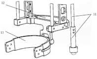
在所有附图中,相同的附图标记用来表示相同的元件或结构,其中:1-背包固定板,2-万向节,3-长度调节杆,4-上横板,5-上侧板,6-侧板加强肋,7-下横板,8-齿轮齿条机构,9-外侧板,10-外侧杆,11-触地杆,12-脚踝架,13-鞋子固定组件,14-阻尼器,15-上三角板,16-下三角板,17-空间连接件,18-滑块组件,19-内侧杆。In all figures, the same reference numerals are used to denote the same elements or structures, wherein: 1-backpack fixing plate, 2-cardan joint, 3-length adjustment rod, 4-upper cross plate, 5-upper side Plate, 6-side plate reinforcement rib, 7-lower cross plate, 8-pinion and pinion mechanism, 9-lateral plate, 10-lateral rod, 11-grounding rod, 12-ankle bracket, 13-shoe fixing assembly, 14 - Damper, 15- Upper triangle plate, 16- Lower triangle plate, 17- Space connector, 18- Slider assembly, 19- Inboard rod.
具体实施方式Detailed ways
为了使本发明的目的、技术方案及优点更加清楚明白,以下结合附图及实施例,对本发明进行进一步详细说明。应当理解,此处所描述的具体实施例仅仅用以解释本发明,并不用于限定本发明。此外,下面所描述的本发明各个实施方式中所涉及到的技术特征只要彼此之间未构成冲突就可以相互组合。In order to make the objectives, technical solutions and advantages of the present invention clearer, the present invention will be further described in detail below with reference to the accompanying drawings and embodiments. It should be understood that the specific embodiments described herein are only used to explain the present invention, but not to limit the present invention. In addition, the technical features involved in the various embodiments of the present invention described below can be combined with each other as long as they do not conflict with each other.
请参阅图1、图2及图6,本发明提供的基于被动变刚度阻尼器的跨关节负重支撑装置,所述支撑装置采用倒立摆机构,其使用非拟人化的设计,极大程度地避免了装置对人体运动的限制。所述支撑装置包括负载支撑机构、离合器机构及变刚度阻尼器机构,所述离合器机构及所述变刚度阻尼器机构分别设置在所述负载支撑机构上,且所述离合器机构与所述变刚度阻尼器机构相连接。Please refer to FIG. 1 , FIG. 2 and FIG. 6 , the cross-joint load-bearing support device based on passive variable stiffness damper provided by the present invention adopts an inverted pendulum mechanism, which uses a non-anthropomorphic design, which greatly avoids the The device restricts the movement of the human body. The support device includes a load support mechanism, a clutch mechanism and a variable stiffness damper mechanism, the clutch mechanism and the variable stiffness damper mechanism are respectively arranged on the load support mechanism, and the clutch mechanism and the variable stiffness damper mechanism are respectively arranged on the load support mechanism. The damper mechanism is connected.
请参阅图5,所述变刚度阻尼器机构包括阻尼器14、上三角板15及下三角板16,所述上三角板15的一端与所述负载支撑机构转动连接,另一端与所述下三角板16的一端转动连接,所述下三角板16的另一端与所述离合器机构转动连接。所述阻尼器14的两端分别可拆卸地连接于所述上三角板15及所述下三角板16,且所述阻尼器14在所述上三角板15及所述下三角板16上的安装位置均可以根据需要进行调节。Please refer to FIG. 5 , the variable stiffness damper mechanism includes a
其中,所述阻尼器14为基于剪切增稠弹性体材料的智能变刚度阻尼器;所述阻尼器内的剪切增稠弹性体材料不受力的情况下,柔软而富有弹性,一旦受到冲击,分子之间迅速相互锁定而收紧变硬,材料从弱刚性迅速变为高刚性;当外界作用力消失,弹性体又立刻恢复到原来的柔软状态。刚度的变化速度和幅度取决于力的作用速度和大小;将剪切增稠弹性体材料放在阻尼器内,阻尼器只要对材料进行封装,并将外力传递给材料,使其刚度发生突变。Wherein, the
其中,人体在运动过程中,髋关节、膝关节和踝关节等神经肌肉系统会随步态周期的不同阶段而变化,调节阻尼器的刚度和阻尼,故阻尼器需要在变刚度的同时也需要调节阻尼。对于一个阻尼器关节,力和位移或者扭矩和转角的关系会形成一个滞回曲线,在一个完整的循环周期内,STG弹性组件的等效阻尼系数可以由公式计算获得,等效阻尼系数随频率的增加呈指数型减小,而振幅对等效阻尼系数几乎无影响。Among them, during the movement of the human body, the neuromuscular systems such as the hip joint, knee joint and ankle joint will change with the different stages of the gait cycle, adjust the stiffness and damping of the damper, so the damper needs to change the stiffness and also need to Adjust damping. For a damper joint, the relationship between force and displacement or torque and rotation angle will form a hysteresis curve. In a complete cycle, the equivalent damping coefficient of the STG elastic component can be calculated by the formula. The equivalent damping coefficient varies with frequency. The increase in , decreases exponentially, while the amplitude has little effect on the equivalent damping coefficient.
请参阅图3,所述离合器机构包括齿轮齿条组件8、触地杆11、空间连接件17及滑块组件18,所述触地杆11活动地连接于所述负载支撑机构。所述滑块组件18包括滑块和直线导轨,所述直线导轨设置在所述负载支撑机构上,所述滑块滑动地连接于所述直线导轨。所述齿轮齿条组件8包括设置在所述负载支撑机构上且同轴设置的两个齿轮(分别为外齿轮及内齿轮)及分别可分离地与两个所述齿轮啮合的两个齿条(分别为第一齿条及第二齿条),两个所述齿条分别连接于所述触地杆11及所述空间连接件17的一端,所述空间连接件17的另一端连接于所述滑块。其中,所述下三角板16远离所述上三角板15的一端转动地连接于所述空间连接件17。Referring to FIG. 3 , the clutch mechanism includes a rack and
在运动过程中,依靠人体运动来被动触发所述离合器机构的开关,并利用所述离合器机构的开关对所述变刚度阻尼器机构进行分时释放与锁定,复现了人体生物的变刚度特性,以实现辅助人体负重行走的目的。During the movement, the switch of the clutch mechanism is passively triggered by the movement of the human body, and the switch of the clutch mechanism is used to release and lock the variable-stiffness damper mechanism in a time-sharing manner, which reproduces the variable-stiffness characteristics of the human body. , in order to achieve the purpose of assisting human weight-bearing walking.
请参阅图4,所述负载支撑机构包括相连接的上部组件及下部组件,所述上部组件包括背包固定板1、万向节2、长度调节杆3、上横板4、上侧板5、侧板加强肋6及下横板7,所述背包固定板1用于承载背包,所述背包用于收容负载。两个所述万向节2的一端转动地连接于所述背包固定板1的两端,另一端分别连接于两个所述长度调节杆3的一端,所述长度调节杆3的另一端连接于所述上横板4的中部。其中,所述长度调节杆3的长度可调,以适应不同的使用者。Referring to FIG. 4 , the load supporting mechanism includes a connected upper component and a lower component, and the upper component includes a
所述下横板7与所述上横板4间隔设置,四个所述上侧板5两两为一组,每组所述上侧板5的两端分别连接所述上横板4及所述下横板7,且每组的两个所述上侧板5间隔设置并由一个所述侧板加强肋6相连接,所述侧板加强肋6邻近所述下横板7设置。所述下横板7包括凹字形件及两个连接件,两个所述连接件分别活动地连接于所述凹字形件的两端。所述上侧板5连接于所述凹字形件。其中,所述触地杆11的一端活动地连接于一个所述连接件,其可以相对于所述连接件移动。The lower
所述下部组件包括外侧板9、外侧杆10、内侧杆19、脚踝架12及鞋子固定组件13,所述内侧杆19及所述外侧杆10的一端依次分别穿过两个所述连接件后活动地连接于所述凹字形件的两端,另一端分别连接于U型的所述脚踝架12的两端。两个所述外侧板9的一端分别连接于两个所述连接件,另一端分别连接于所述脚踝架12的两端。所述触地杆11的另一端连接有万向球,其可以相对于所述连接件做直线运动;且所述触地杆11通过直线轴承连接于所述外侧板9。其中,两个所述齿轮分别设置在邻近所述触地杆11的外侧板9上,所述直线导轨设置在另一个所述外侧板9朝向所述齿轮齿条机构8的一侧上。所述鞋子固定组件13连接于所述脚踝架12。The lower assembly includes an
本实施方式中,所述鞋子固定组件13包括第一踝轴、脚架连接件、第二踝轴、U型脚架、基板连接脚架及基板,所述第一踝轴的两端分别转动地连接于所述脚踝架12及所述脚架连接件的一端,所述脚架连接件的另一端通过所述第二踝轴转动地连接于所述U型脚架,所述U型脚架的两端分别连接有基板连接脚架,所述基板连接脚架远离所述脚踝架12的一端连接有基板,所述基板用于与鞋子的橡胶底相连接,而不是与人体的踝关节进行固连或者柔性绑带连接,对人体和底面没有干涉,可以提高穿戴的轻便性。In this embodiment, the
所述支撑装置工作时,在支撑相开始时(步态周期0点),所述触地杆11随着人体脚后跟着地而接触地面,并受压向上运动约20毫米,所述触地杆11带动所述齿条向上运动,使得所述齿条与外侧齿轮进入啮合状态,与此同时,本就处于啮合状态的另一齿条与内侧齿轮进行拟合运动,且始终未脱离,这种状态记为所述离合器机构处于关闭状态。期间的支撑相阶段,所述背包的负重经由所述负载支撑机构、所述变刚度阻尼器机构传递到所述空间连接件17,迫使所述空间连接件17向下运动,所述空间连接件17的向下运动趋势依次传递给所述齿条、内侧齿轮、外侧齿轮、另一个齿条及所述触地杆11,但是由于所述触地杆11的下端触地,无法向下运动,所述空间连接件17只能冲击所述阻尼器14,使得所述阻尼器14变为高刚度,然后将背包的负重通过所述触地杆11传递到地面。When the support device is working, at the beginning of the support phase (0 point of the gait cycle), the
在脚后跟离地时(步态周期40%点),所述触地杆11在自重及所述阻尼器14弹力的作用下而向下运动,使得齿条与外齿轮脱离啮合,齿轮齿条机构释放并可自由转动,所述离合器机构进入打开状态,与所述离合器机构连接的阻尼器被释放。期间,所述阻尼器恢复低刚度状态而随人体自由摆动。其中,支撑装置长度的减小或者增大转化为阻尼器随所述空间连接件17及所述滑块在所述直线导轨上做往复直线运动。在摆动相末期,齿条与内侧齿轮进入啮合状态,脚后跟准备着地,并开始下个步态周期,重复上述运动过程。When the heel is off the ground (40% point of the gait cycle), the
本领域的技术人员容易理解,以上所述仅为本发明的较佳实施例而已,并不用以限制本发明,凡在本发明的精神和原则之内所作的任何修改、等同替换和改进等,均应包含在本发明的保护范围之内。Those skilled in the art can easily understand that the above are only preferred embodiments of the present invention, and are not intended to limit the present invention. Any modifications, equivalent replacements and improvements made within the spirit and principles of the present invention, etc., All should be included within the protection scope of the present invention.
Claims (9)
Priority Applications (1)
| Application Number | Priority Date | Filing Date | Title |
|---|---|---|---|
| CN202110425447.3ACN113146579B (en) | 2021-04-20 | 2021-04-20 | A cross-joint load-bearing support device based on passive variable stiffness damper |
Applications Claiming Priority (1)
| Application Number | Priority Date | Filing Date | Title |
|---|---|---|---|
| CN202110425447.3ACN113146579B (en) | 2021-04-20 | 2021-04-20 | A cross-joint load-bearing support device based on passive variable stiffness damper |
Publications (2)
| Publication Number | Publication Date |
|---|---|
| CN113146579A CN113146579A (en) | 2021-07-23 |
| CN113146579Btrue CN113146579B (en) | 2022-06-21 |
Family
ID=76867561
Family Applications (1)
| Application Number | Title | Priority Date | Filing Date |
|---|---|---|---|
| CN202110425447.3AActiveCN113146579B (en) | 2021-04-20 | 2021-04-20 | A cross-joint load-bearing support device based on passive variable stiffness damper |
Country Status (1)
| Country | Link |
|---|---|
| CN (1) | CN113146579B (en) |
Families Citing this family (3)
| Publication number | Priority date | Publication date | Assignee | Title |
|---|---|---|---|---|
| CN113842140B (en)* | 2021-09-18 | 2023-12-08 | 中南大学 | Patient function detection device after knee joint operation |
| CN115972182B (en)* | 2023-02-23 | 2024-09-13 | 天津大学 | Pure passive type load exoskeleton robot |
| CN116901035B (en)* | 2023-06-28 | 2025-09-16 | 华中科技大学 | Arc-shaped foot supporting device for lower limb load exoskeleton |
Family Cites Families (7)
| Publication number | Priority date | Publication date | Assignee | Title |
|---|---|---|---|---|
| US9682005B2 (en)* | 2012-02-24 | 2017-06-20 | Massachusetts Institute Of Technology | Elastic element exoskeleton and method of using same |
| CN104490498B (en)* | 2014-12-16 | 2016-08-24 | 郑州大学 | Knee joint ankle joint coordinated type lower artificial limb device |
| CN106618830B (en)* | 2016-12-30 | 2019-06-18 | 北京林业大学 | A single lower limb exoskeleton orthosis and orthopedic control method |
| CN206785913U (en)* | 2017-02-15 | 2017-12-22 | 株洲联诚集团减振器有限责任公司 | Guided bearing seat with damping regulatory function |
| CN109528451B (en)* | 2018-09-14 | 2019-10-08 | 华中科技大学 | A passive exoskeleton device with hip and knee joints based on clutch time-sharing control |
| CN210912116U (en)* | 2019-10-18 | 2020-07-03 | 安路普(北京)汽车技术有限公司 | Device, seat and vehicle suspension system for adjusting damping force and height |
| CN111096876B (en)* | 2019-11-14 | 2024-05-14 | 清华大学 | Lower limb weight-bearing mobility exoskeleton |
- 2021
- 2021-04-20CNCN202110425447.3Apatent/CN113146579B/enactiveActive
Also Published As
| Publication number | Publication date |
|---|---|
| CN113146579A (en) | 2021-07-23 |
Similar Documents
| Publication | Publication Date | Title |
|---|---|---|
| CN113146579B (en) | A cross-joint load-bearing support device based on passive variable stiffness damper | |
| US11071675B2 (en) | Lower limb exoskeleton system having jump-down cushioning function and method of using the same | |
| CN103610568B (en) | Human-simulated external skeleton robot assisting lower limbs | |
| Asbeck et al. | A biologically inspired soft exosuit for walking assistance | |
| Wiggin et al. | An exoskeleton using controlled energy storage and release to aid ankle propulsion | |
| CN204618765U (en) | Exercising apparatus for recovery of upper limb | |
| CN105643598B (en) | The semi-passive lower limb exoskeleton of energy-conservation driven based on lasso trick | |
| CN206085037U (en) | Wearable heavy burden ectoskeleton | |
| Li et al. | Mechanical compliance and dynamic load isolation design of lower limb exoskeleton for locomotion assistance | |
| CN111096876B (en) | Lower limb weight-bearing mobility exoskeleton | |
| CN112388617B (en) | Lower limb exoskeleton robot | |
| CN107625565A (en) | Wearable active bionical artificial limb anklebone joint mechanism based on metamorphic mechanisms | |
| Xing et al. | A survey on flexible exoskeleton robot | |
| Xie et al. | Design of a soft bionic elbow exoskeleton based on shape memory alloy spring actuators | |
| CN107042502A (en) | Closed chain link-type drive lacking lower limb exoskeleton mechanism | |
| CN206855436U (en) | Multi freedom degree mechanical exoskeleton device | |
| CN204501524U (en) | A kind of ectoskeleton three-degree of freedom flexible ankle device | |
| CN221111812U (en) | Non-anthropomorphic novel load exoskeleton robot | |
| Long et al. | Snow Leopard-inspired Lower Limb Exoskeleton for Adaptive Multi-terrain Locomotion: Design and Preliminary Experimental Evaluation | |
| Yali et al. | Kinematics analysis of lower extremity exoskeleton | |
| CN104055653A (en) | Lower-limb reinforced exoskeleton robot with series-parallel leg structure | |
| Shi et al. | Design and research of eight-link rehabilitation training robot based on single degree of freedomitle | |
| Guo et al. | Design and analysis of a lower limb exoskeleton robot | |
| Jiang et al. | Lower Limb Exoskeleton Design Based on Knee Joint Assistance | |
| Shi et al. | Design of a passive lower limb exoskeleton with cable-driven remote gravity compensation mechansims |
Legal Events
| Date | Code | Title | Description |
|---|---|---|---|
| PB01 | Publication | ||
| PB01 | Publication | ||
| SE01 | Entry into force of request for substantive examination | ||
| SE01 | Entry into force of request for substantive examination | ||
| GR01 | Patent grant | ||
| GR01 | Patent grant |