CN113132604B - Electronic device - Google Patents
Electronic deviceDownload PDFInfo
- Publication number
- CN113132604B CN113132604BCN202110444589.4ACN202110444589ACN113132604BCN 113132604 BCN113132604 BCN 113132604BCN 202110444589 ACN202110444589 ACN 202110444589ACN 113132604 BCN113132604 BCN 113132604B
- Authority
- CN
- China
- Prior art keywords
- circuit board
- light guide
- module
- hole
- camera
- Prior art date
- Legal status (The legal status is an assumption and is not a legal conclusion. Google has not performed a legal analysis and makes no representation as to the accuracy of the status listed.)
- Active
Links
- 238000000034methodMethods0.000description10
- 238000013459approachMethods0.000description9
- 238000010586diagramMethods0.000description9
- 230000005540biological transmissionEffects0.000description7
- 230000000694effectsEffects0.000description7
- 238000009434installationMethods0.000description7
- 230000033001locomotionEffects0.000description7
- 230000003287optical effectEffects0.000description5
- 238000012546transferMethods0.000description3
- 238000004891communicationMethods0.000description2
- 238000013461designMethods0.000description2
- 238000011161developmentMethods0.000description1
- 230000002452interceptive effectEffects0.000description1
- 238000012545processingMethods0.000description1
- 238000007789sealingMethods0.000description1
- 230000000007visual effectEffects0.000description1
Images


Classifications
- H—ELECTRICITY
- H04—ELECTRIC COMMUNICATION TECHNIQUE
- H04N—PICTORIAL COMMUNICATION, e.g. TELEVISION
- H04N23/00—Cameras or camera modules comprising electronic image sensors; Control thereof
- H04N23/50—Constructional details
- H04N23/55—Optical parts specially adapted for electronic image sensors; Mounting thereof
- G—PHYSICS
- G09—EDUCATION; CRYPTOGRAPHY; DISPLAY; ADVERTISING; SEALS
- G09F—DISPLAYING; ADVERTISING; SIGNS; LABELS OR NAME-PLATES; SEALS
- G09F9/00—Indicating arrangements for variable information in which the information is built-up on a support by selection or combination of individual elements
- G09F9/30—Indicating arrangements for variable information in which the information is built-up on a support by selection or combination of individual elements in which the desired character or characters are formed by combining individual elements
- H—ELECTRICITY
- H04—ELECTRIC COMMUNICATION TECHNIQUE
- H04M—TELEPHONIC COMMUNICATION
- H04M1/00—Substation equipment, e.g. for use by subscribers
- H04M1/02—Constructional features of telephone sets
- H04M1/0202—Portable telephone sets, e.g. cordless phones, mobile phones or bar type handsets
- H04M1/026—Details of the structure or mounting of specific components
- H04M1/0264—Details of the structure or mounting of specific components for a camera module assembly
- H—ELECTRICITY
- H04—ELECTRIC COMMUNICATION TECHNIQUE
- H04M—TELEPHONIC COMMUNICATION
- H04M1/00—Substation equipment, e.g. for use by subscribers
- H04M1/02—Constructional features of telephone sets
- H04M1/0202—Portable telephone sets, e.g. cordless phones, mobile phones or bar type handsets
- H04M1/026—Details of the structure or mounting of specific components
- H04M1/0277—Details of the structure or mounting of specific components for a printed circuit board assembly
- H—ELECTRICITY
- H04—ELECTRIC COMMUNICATION TECHNIQUE
- H04N—PICTORIAL COMMUNICATION, e.g. TELEVISION
- H04N23/00—Cameras or camera modules comprising electronic image sensors; Control thereof
- H04N23/57—Mechanical or electrical details of cameras or camera modules specially adapted for being embedded in other devices
- H—ELECTRICITY
- H04—ELECTRIC COMMUNICATION TECHNIQUE
- H04N—PICTORIAL COMMUNICATION, e.g. TELEVISION
- H04N23/00—Cameras or camera modules comprising electronic image sensors; Control thereof
- H04N23/70—Circuitry for compensating brightness variation in the scene
- H04N23/71—Circuitry for evaluating the brightness variation
- Y—GENERAL TAGGING OF NEW TECHNOLOGICAL DEVELOPMENTS; GENERAL TAGGING OF CROSS-SECTIONAL TECHNOLOGIES SPANNING OVER SEVERAL SECTIONS OF THE IPC; TECHNICAL SUBJECTS COVERED BY FORMER USPC CROSS-REFERENCE ART COLLECTIONS [XRACs] AND DIGESTS
- Y02—TECHNOLOGIES OR APPLICATIONS FOR MITIGATION OR ADAPTATION AGAINST CLIMATE CHANGE
- Y02B—CLIMATE CHANGE MITIGATION TECHNOLOGIES RELATED TO BUILDINGS, e.g. HOUSING, HOUSE APPLIANCES OR RELATED END-USER APPLICATIONS
- Y02B20/00—Energy efficient lighting technologies, e.g. halogen lamps or gas discharge lamps
- Y02B20/40—Control techniques providing energy savings, e.g. smart controller or presence detection
Landscapes
- Engineering & Computer Science (AREA)
- Signal Processing (AREA)
- Multimedia (AREA)
- Physics & Mathematics (AREA)
- General Physics & Mathematics (AREA)
- Theoretical Computer Science (AREA)
- Studio Devices (AREA)
Abstract
Translated fromChinese
Description
Translated fromChinese技术领域technical field
本申请属于通信技术领域,具体涉及一种电子设备。The present application belongs to the technical field of communication, and specifically relates to an electronic device.
背景技术Background technique
随着电子的不断发展,电子设备的性能也越来越强大。为使用户具有更佳的视觉体验,许多电子设备采用全面屏设计。在电子设备具有拍摄功能的前提下,为了让全面屏的屏占比最大化,通常电子设备采用伸缩式摄像头。With the continuous development of electronics, the performance of electronic equipment is becoming more and more powerful. In order to provide users with a better visual experience, many electronic devices adopt a full-screen design. On the premise that the electronic device has a shooting function, in order to maximize the screen-to-body ratio of the full screen, the electronic device usually adopts a retractable camera.
目前,电子设备包括摄像头模组、印制电路板(PrintedCircuit Board,PCB)、发光二极管、导光灯罩和触摸显示屏。安装时,摄像头模组嵌装在导光灯罩内,导光灯罩固定PCB和触摸显示屏之间,发光二极管粘贴在PCB上,且靠近导光灯罩的一端,导光灯罩的另一端位于触摸显示屏的背光模组的前摄孔中,发光二极管发出的光线通过导光灯罩传给触摸显示屏。为实现触摸显示屏的全面屏效果,同时实现了触摸显示屏屏下拍照和摄像功能,在导光灯罩靠近触摸显示屏的一端的中部开设有通孔。At present, electronic devices include camera modules, printed circuit boards (Printed Circuit Board, PCB), light-emitting diodes, light guide lampshades, and touch screens. During installation, the camera module is embedded in the light guide lamp cover, the light guide lamp cover is fixed between the PCB and the touch display screen, the light-emitting diode is pasted on the PCB, and is close to one end of the light guide lamp cover, and the other end of the light guide lamp cover is located on the touch display screen. In the front camera hole of the backlight module of the screen, the light emitted by the light emitting diode is transmitted to the touch display screen through the light guide lamp cover. In order to realize the full-screen effect of the touch display screen and simultaneously realize the functions of taking pictures and taking pictures under the touch display screen, a through hole is opened in the middle of the end of the light guide lamp cover close to the touch display screen.
然而,在实现本申请过程中,申请人发现现有技术中至少存在如下问题:由于在导光灯罩靠近触摸显示屏的一端的中部开设有通孔,因此导致发光二极管发出的光线在导光灯罩的开设通孔的区域难以实线均匀的亮度,进而降低了显示屏的全面屏显示的效果。However, in the process of implementing this application, the applicant found that at least the following problems exist in the prior art: since a through hole is opened in the middle of the end of the light guide lamp cover close to the touch display screen, the light emitted by the light-emitting diodes is caused to pass through the light guide lamp cover. It is difficult to achieve uniform brightness in the area where the through hole is opened, thereby reducing the full-screen display effect of the display screen.
实用新型内容Utility model content
本申请实施例的目的是提供一种电子设备,能够解决导光灯罩的开设通孔的区域难以实线均匀的亮度,进而降低显示屏的全面屏显示效果问题。The purpose of the embodiments of the present application is to provide an electronic device, which can solve the problem that it is difficult to achieve uniform brightness in the area where the through hole is opened in the light guide cover, thereby reducing the full-screen display effect of the display screen.
为了解决上述技术问题,本申请是这样实现的:In order to solve the above-mentioned technical problems, the application is implemented as follows:
本申请实施例提供了一种电子设备,所述电子设备包括驱动模组、摄像头模组、导光模组、背光模组、主电路板和承载电路板;An embodiment of the present application provides an electronic device, and the electronic device includes a drive module, a camera module, a light guide module, a backlight module, a main circuit board, and a carrier circuit board;
所述驱动模组包括第一驱动件、第二驱动件和第三驱动件,所述摄像头模组通过所述第一驱动件活动连接在所述承载电路板上,所述导光模组通过所述第二驱动件活动连接在所述承载电路板上,在所述第一驱动件的驱动下,所述摄像头模组远离或者靠近所述承载电路板,在所述第二驱动件的驱动下,所述导光模组远离或者靠近所述承载电路板,其中,所述导光模组内均匀设置有多个发光元件;The driving module includes a first driving part, a second driving part and a third driving part, the camera module is movably connected to the carrier circuit board through the first driving part, and the light guide module is connected through the The second driver is movably connected to the carrier circuit board, driven by the first driver, the camera module is away from or close to the carrier circuit board, driven by the second driver Next, the light guide module is far away from or close to the carrier circuit board, wherein a plurality of light emitting elements are uniformly arranged in the light guide module;
所述承载电路板通过所述第三驱动件铰接在所述主电路板上,在所述第三驱动件的驱动下,所述承载电路板绕垂直于所述主电路板的轴线转动以使所述承载电路板位于第一位置和第二位置;The carrying circuit board is hinged on the main circuit board through the third driving member, driven by the third driving member, the carrying circuit board rotates around an axis perpendicular to the main circuit board so that The carrying circuit board is located at a first position and a second position;
其中,所述背光模组上开设有通孔,在所述承载电路板位于第一位置的情况下,所述摄像头模组可在所述第一驱动件的带动下嵌入至所述通孔中;在所述承载电路板位于第二位置的情况下,所述导光模组可在所述第二驱动件的带动下嵌入至所述通孔中。Wherein, a through hole is opened on the backlight module, and when the carrying circuit board is located at the first position, the camera module can be embedded into the through hole driven by the first driving member ; when the carrying circuit board is at the second position, the light guide module can be embedded into the through hole driven by the second driving member.
在本申请实施例中,由于在第一驱动件的驱动下,摄像头模组远离或者靠近承载电路板,在第二驱动件的驱动下,导光模组远离或者靠近承载电路板,承载电路板通过第三驱动件铰接在主电路板上,在第三驱动件的驱动下,承载电路板绕垂直于主电路板的轴线转动以使承载电路板位于第一位置或者第二位置,因此可以通过第一驱动件、第二驱动件和第三驱动件改变摄像头模组、导光模组和背光模组的相对位置。在电子设备需要拍摄时,通过第三驱动件带动承载电路板转动,直至承载电路板上安装的摄像头模组和摄像背光模组的中部开设有通孔对齐,之后通过第二驱动件控制控制导光模组靠近承载电路板,通过第一驱动件控制摄像头模组远离承载电路板,直至摄像头模组嵌入通孔中。电子设备拍摄完成后,通过第一驱动件控制摄像头模组靠近承载电路板,远离背光模组中部开设的通孔,之后通过第三驱动件带动承载电路板转动,直至承载电路板上安装的导光模组和摄像背光模组的中部开设有通孔对齐,最后通过第二驱动件控制导光模组远离承载电路板,直至导光模组嵌入通孔中,使得背光模组开设的通孔不会影响光线的传播,进而使得发光元件发出的光线可以直接经过导光灯罩折射后到达背光模组,又由于导光模组内均匀设置有多个发光元件,因此本申请实施例的电子设备在实现显示屏屏下拍照和摄像功能的同时,可以使得发光元件发出的光线在到达背光模组时可以保持均匀的亮度,进而有利于提高显示屏的全面屏显示的效果。In the embodiment of the present application, since the camera module is driven away from or close to the carrying circuit board under the driving of the first driving part, and the light guide module is away from or close to the carrying circuit board under the driving of the second driving part, the carrying circuit board The third driving member is hinged on the main circuit board, driven by the third driving member, the carrying circuit board rotates around an axis perpendicular to the main circuit board so that the carrying circuit board is located at the first position or the second position, so it can pass The first driving part, the second driving part and the third driving part change the relative positions of the camera module, the light guide module and the backlight module. When the electronic equipment needs to be photographed, the third driving part drives the carrying circuit board to rotate until the camera module installed on the carrying circuit board and the middle part of the camera backlight module are aligned with the through holes, and then the second driving part is used to control the guide. The optical module is close to the carrying circuit board, and the camera module is controlled to be far away from the carrying circuit board through the first driver until the camera module is embedded in the through hole. After the shooting of the electronic equipment is completed, the camera module is controlled to be close to the carrying circuit board through the first driving part, away from the through hole opened in the middle of the backlight module, and then the carrying circuit board is driven to rotate by the third driving part until the guide installed on the carrying circuit board The middle part of the optical module and the camera backlight module is aligned with a through hole, and finally the second driver is used to control the light guide module away from the carrying circuit board until the light guide module is embedded in the through hole, so that the through hole opened by the backlight module It will not affect the propagation of light, so that the light emitted by the light-emitting element can be directly refracted by the light guide lampshade and then reach the backlight module, and because a plurality of light-emitting elements are uniformly arranged in the light guide module, the electronic device of the embodiment of the present application While realizing the functions of photographing and video recording under the display screen, the light emitted by the light-emitting element can maintain a uniform brightness when it reaches the backlight module, thereby helping to improve the full-screen display effect of the display screen.
附图说明Description of drawings
为了更清楚地说明本申请实施例的技术方案,下面将对本申请实施例的描述中所需要使用的附图作简单地介绍,显而易见地,下面描述中的附图仅仅是本申请的一些实施例,对于本领域普通技术人员来讲,在不付出创造性劳动性的前提下,还可以根据这些附图获得其他的附图。In order to more clearly illustrate the technical solutions of the embodiments of the present application, the following will briefly introduce the accompanying drawings that need to be used in the description of the embodiments of the present application. Obviously, the accompanying drawings in the following description are only some embodiments of the present application , for those skilled in the art, other drawings can also be obtained according to these drawings without paying creative labor.
图1是本申请实施例提供的电子设备的爆炸结构示意图;FIG. 1 is a schematic diagram of an exploded structure of an electronic device provided in an embodiment of the present application;
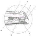
图2是本申请实施例提供的电子设备在拍摄状态下的截面示意图;2 is a schematic cross-sectional view of an electronic device provided in an embodiment of the present application in a shooting state;
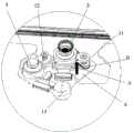
图3是本申请实施例提供的电子设备在非拍摄状态下的截面示意图;3 is a schematic cross-sectional view of an electronic device provided in an embodiment of the present application in a non-shooting state;
图4是本申请实施例提供的摄像头模组和第一驱动件的安装示意图;Fig. 4 is a schematic diagram of the installation of the camera module and the first driver provided by the embodiment of the present application;
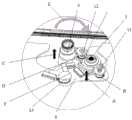
图5是本申请实施例提供的导光模组和第二驱动件的安装示意图;Fig. 5 is a schematic diagram of the installation of the light guide module and the second driver provided by the embodiment of the present application;
图6是本申请实施例提供的承载电路板和第三驱动件的安装示意图;Fig. 6 is a schematic diagram of the installation of the carrier circuit board and the third driver provided by the embodiment of the present application;
图7是本申请实施例提供的电子设备在初始状态下的局部结构示意图;FIG. 7 is a schematic diagram of a partial structure of an electronic device provided in an embodiment of the present application in an initial state;
图8是本申请实施例提供的电子设备在拍摄状态下的局部结构示意图;FIG. 8 is a schematic diagram of a partial structure of an electronic device provided in an embodiment of the present application in a shooting state;
图9是本申请实施例提供的电子设备在非拍摄状态下的局部结构示意图。FIG. 9 is a schematic diagram of a partial structure of an electronic device provided in an embodiment of the present application in a non-shooting state.
附图标记:Reference signs:
1-驱动模组;2-摄像头模组;3-导光模组;4-背光模组;5-主电路板;6-承载电路板;7-发光元件;8-转接电路板;11-第一驱动件;12-第二驱动件;13-第三驱动件;21-摄像头主体;22-摄像头固定板;31-导光灯罩;32-灯罩固定板;33-导光电路板;34-控制芯片;111-第一贴片马达;112-第一丝杆;113-第一限位螺母;121-第二贴片马达;122-第二丝杆;123-第二限位螺母;131-第三贴片马达;132-固定片。1-Drive module; 2-Camera module; 3-Light guide module; 4-Backlight module; 5-Main circuit board; - the first driver; 12-the second driver; 13-the third driver; 21-camera body; 22-camera fixing plate; 31-light guide lampshade; 32-lampshade fixing plate; 34-control chip; 111-the first patch motor; 112-the first screw; 113-the first limit nut; 121-the second patch motor; 122-the second screw; 123-the second limit nut ; 131 - the third patch motor; 132 - the fixed piece.
具体实施方式Detailed ways
下面将结合本申请实施例中的附图,对本申请实施例中的技术方案进行清楚、完整地描述,显然,所描述的实施例是本申请一部分实施例,而不是全部的实施例。基于本申请中的实施例,本领域普通技术人员在没有作出创造性劳动前提下所获得的所有其他实施例,都属于本申请保护的范围。The following will clearly and completely describe the technical solutions in the embodiments of the present application with reference to the drawings in the embodiments of the present application. Obviously, the described embodiments are part of the embodiments of the present application, not all of them. Based on the embodiments in this application, all other embodiments obtained by persons of ordinary skill in the art without creative efforts fall within the protection scope of this application.
本申请的说明书和权利要求书中的术语“第一”、“第二”等是用于区别类似的对象,而不用于描述特定的顺序或先后次序。应该理解这样使用的数据在适当情况下可以互换,以便本申请的实施例能够以除了在这里图示或描述的那些以外的顺序实施。此外,说明书以及权利要求中“和/或”表示所连接对象的至少其中之一,字符“/”,一般表示前后关联对象是一种“或”的关系。The terms "first", "second" and the like in the specification and claims of the present application are used to distinguish similar objects, and are not used to describe a specific sequence or sequence. It is to be understood that the data so used are interchangeable under appropriate circumstances such that the embodiments of the application can be practiced in sequences other than those illustrated or described herein. In addition, "and/or" in the specification and claims means at least one of the connected objects, and the character "/" generally means that the related objects are an "or" relationship.
下面结合附图,通过具体的实施例及其应用场景对本申请实施例提供的电子设备进行详细地说明。图1是本申请实施例提供的电子设备的爆炸结构示意图,图2是本申请实施例提供的电子设备在拍摄状态下的截面示意图,图3是本申请实施例提供的电子设备在非拍摄状态下的截面示意图,如图1~图3所示,该电子设备包括驱动模组1、摄像头模组2、导光模组3、背光模组4、主电路板5和承载电路板6;驱动模组1包括第一驱动件11、第二驱动件12和第三驱动件13,摄像头模组2通过第一驱动件11活动连接在承载电路板6上,导光模组3通过第二驱动件12活动连接在承载电路板6上,在第一驱动件11的驱动下,摄像头模组2远离或者靠近承载电路板6,在第二驱动件12的驱动下,导光模组3远离或者靠近承载电路板6,其中,导光模组3内均匀设置有多个发光元件7;承载电路板6通过第三驱动件13铰接在主电路板5上,在第三驱动件13的驱动下,承载电路板6绕垂直于主电路板5的轴线转动以使承载电路板6位于第一位置或者第二位置;背光模组4上开设有通孔,在承载电路板6位于第一位置的情况下,摄像头模组2可在第一驱动件11的带动下嵌入至通孔中,在承载电路板6位于第二位置的情况下,导光模组3可在第二驱动件12的带动下嵌入至通孔中。The electronic device provided by the embodiments of the present application will be described in detail below through specific embodiments and application scenarios with reference to the accompanying drawings. Figure 1 is a schematic diagram of the exploded structure of the electronic device provided by the embodiment of the present application, Figure 2 is a schematic cross-sectional view of the electronic device provided by the embodiment of the present application in the shooting state, and Figure 3 is a schematic diagram of the electronic device provided by the embodiment of the present application in the non-shooting state As shown in Figures 1 to 3, the electronic device includes a drive module 1, a
其中,该电子设备可以为:手机、平板电脑、电子书阅读器、MP3播放器、MP4播放器、膝上型便携计算机、车载电脑、台式计算机、机顶盒、智能电视机或可穿戴设备。Wherein, the electronic device may be: a mobile phone, a tablet computer, an e-book reader, an MP3 player, an MP4 player, a laptop computer, a vehicle computer, a desktop computer, a set-top box, a smart TV or a wearable device.
需要说明的是,该电子设备包括的驱动模组1、摄像头模组2、导光模组3、背光模组4、主电路板5和承载电路板6均可以固定在设备外壳中。其中,用于拍摄的摄像头模组2通常可以包括前置摄像头模组和后置摄像头模组,前置摄像头模组用于用户的自拍,后置摄像头模组用于用户拍摄其它景物或者人物。随着电子设备采用全面屏设计,前置摄像头通常设置在显示屏内部。本申请实施例中所述的摄像头模组2为用于用户自拍的前置摄像头模组。It should be noted that the drive module 1 ,
还需要说明的是,摄像头模组2可以包括图像传感器、镜头、固定器、滤色片、传感器、其它部件,在一种可能实现的方式中,该摄像头模组2的工作原理可以为:镜头将生成的光学图像投射到传感器上,之后光学图像被转换成电信号,电信号再转换为数字信号,数字信号经过加工处理,再传递到主电路板5上进行处理,最终转换成电子设备的显示屏上能够看到的图像。It should also be noted that the
位于摄像头模组2一侧的导光模组3用于传导发光元件7发出的光线。导光模组3可以包括导光灯罩31、发光元件7等器件,发光元件7固定在导光灯罩31内,为使透过导光灯罩31到达背光模组4的光线较为均匀,固定在导光灯罩31内的多个发光元件7需要均匀设置。示例性的,在导光灯罩31为圆柱形壳体的情况下,多个发光元件7可以绕设于导光灯罩31内腔的轴线一周,即每个发光元件7和导光灯罩31的轴线之间的距离相等。The
为使摄像头模组2和导光模组3互不干涉,在本申请实施例中,摄摄像头模组2通过第一驱动件11活动连接在承载电路板6上,导光模组3通过第二驱动件12活动连接在承载电路板6上。具体的,摄像头模组2通过第一驱动件11活动连接在承载电路板6上,以使摄像头模组2可以在第一驱动件11的驱动下远离或者靠近承载电路板6,如图2所示,在电子设备进行拍摄时,使得摄像头模组2远离承载电路板6,在电子设备拍摄完成时,使得摄像头模组2靠近承载电路板6,进而为导光模组3预留出合适的位置。导光模组3通过第二驱动件12活动连接在承载电路板6上,在摄像头模组2进行拍摄时,使得导光模组3靠近承载电路板6,为摄像头模组2预留伸缩空间,如图3所示,在摄像头模组2拍摄完成后,使得导光模组3远离承载电路板6,进而使得导光模组3可以更好的发挥光线传播的作用。In order to prevent the
需要说明的是,本申请实施例提供的第一驱动件11和第二驱动件12均可以为电机螺杆、气缸推杆、滑轨滑块等可以使摄像头模组2和导光模组3做往复直线运动的任一驱动件,本申请实施例对此不做限定。在安装时,可以将第一驱动件11和第二驱动件12固定在承载电路板6上,再将摄像头模组2和导光模组3分被固定第一驱动件11和第二驱动件12上,其中,摄像头模组2远离或者靠近承载电路板6的方向和第一驱动件11的驱动方向一致,导光模组3远离或者靠近承载电路板6的方向和第一驱动件11的驱动方向一致。It should be noted that the first driving
还需要说明的是,主电路板5和承载电路板6均为电子设备中用于连接电子元件和传递信号的印制电路板的一种,主电路板5和承载电路板6可以为单面板、双面板和多层线路板中的任一种,本申请实施例对此不做限定。在本申请实施例中,承载电路板6用于承载摄像头模组2和导光模组3,承载电路板6和主电路板5层叠设置,通过第三驱动件13铰接在主电路板5上,以使承载电路板6可以绕垂直于主电路板5的轴线转动,当通过摄像头模组2进行拍摄时,使得承载电路板6处于第一位置,当摄像头模组2进行拍摄完成后,使得承载电路板6处于第二位置,进而实现摄像头模组2和导光模组3在空间上的切换。其中,第三驱动件13可以为电机转轴、电机齿轮等能够实现承载电路板6的驱动件,本申请实施例对此不做限定。It should also be noted that both the
此外,承载电路板6可以为圆形板、方形板、扇形板等任意形状的电路板,为在减小承载电路板6占用空间的同时,方便承载电路板6转动,优选承载电路板6为扇形板,承载电路板6宽度较窄的一端铰接在主电路板5上,承载电路板6宽度较宽的一端的表面上可以用于承载摄像头模组2和导光模组3。In addition, the carrying
为了让显示屏的屏占比最大化,通常摄像头模组2采用伸缩式摄像头,而为了给伸缩式摄像头留有充足的伸缩空间,在摄像背光模组4的上开设有通孔,通孔的轴线可以为位于摄像背光模组4的中轴线重合。背光模组4为照亮显示屏的主要部件,在本申请实施例中,背光模组4为传递发光元件7发出的光线的主要部件,位于显示屏的背光面。In order to maximize the screen-to-body ratio of the display screen, the
具体的,如图2所示,在电子设备需要拍摄时,通过第三驱动件13带动承载电路板6转动,直至承载电路板6上安装的摄像头模组2和摄像背光模组4的中部开设有通孔对齐,之后通过第二驱动件12控制控制导光模组3靠近承载电路板6,通过第一驱动件11控制摄像头模组2远离承载电路板6,直至摄像头模组2嵌入通孔中。即在承载电路板6位于第一位置,且摄像头模组2远离靠近所述承载电路板6的情况下。如图3所示,在电子设备拍摄完成后,通过第一驱动件11控制摄像头模组2靠近承载电路板6,远离背光模组4中部开设的通孔,之后通过第三驱动件13带动承载电路板6转动,直至承载电路板6上安装的导光模组3和摄像背光模组4的中部开设有通孔对齐,最后通过第二驱动件12控制导光模组3远离承载电路板6,直至导光模组3嵌入通孔中。即在承载电路板6位于第二位置,且导光模组3远离靠近所述承载电路板6的情况下。Specifically, as shown in FIG. 2 , when the electronic device needs to take pictures, the third driving
在本申请实施例中,由于在第一驱动件11的驱动下,摄像头模组2远离或者靠近承载电路板6,在第二驱动件12的驱动下,导光模组3远离或者靠近承载电路板6,承载电路板6通过第三驱动件13铰接在主电路板5上,在第三驱动件13的驱动下,承载电路板6绕垂直于主电路板5的轴线转动以使承载电路板6位于第一位置或者第二位置,因此可以通过第一驱动件11、第二驱动件12和第三驱动件13改变摄像头模组2、导光模组3和背光模组4的相对位置。在电子设备需要拍摄时,通过第三驱动件13带动承载电路板6转动,直至承载电路板6上安装的摄像头模组2和摄像背光模组4的中部开设有通孔对齐,之后通过第二驱动件12控制控制导光模组3靠近承载电路板6,通过第一驱动件11控制摄像头模组2远离承载电路板6,直至摄像头模组2嵌入通孔中。电子设备拍摄完成后,通过第一驱动件11控制摄像头模组2靠近承载电路板6,远离背光模组4中部开设的通孔,之后通过第三驱动件13带动承载电路板6转动,直至承载电路板6上安装的导光模组3和摄像背光模组4的中部开设有通孔对齐,最后通过第二驱动件12控制导光模组3远离承载电路板6,直至导光模组3嵌入通孔中,使得背光模组4开设的通孔不会影响光线的传播,进而使得发光元件7发出的光线可以直接经过导光灯罩31折射后到达背光模组4,又由于导光模组3内均匀设置有多个发光元件7,因此本申请实施例的电子设备在实现显示屏屏下拍照和摄像功能的同时,可以使得发光元件7发出的光线在到达背光模组4时可以保持均匀的亮度,进而有利于提高显示屏的全面屏显示的效果。In the embodiment of the present application, since the
可选的,如图1、图4和图8所示,第一驱动件11包括第一贴片马达111和第一丝杆112,摄像头模组2包括摄像头主体21和摄像头固定板22;摄像头主体21固定在摄像头固定板22上,摄像头固定板22上开设有第一螺纹孔和第一限位孔,承载电路板6上开设有第二限位孔;第一贴片马达111固定在承载电路板上,第一贴片马达111包括第一马达主体和第一螺杆,第一螺杆固定在第一马达主体上,第一螺杆螺连接在摄像头固定板22上,且和第一螺纹孔配合连接;第一限位孔和第二限位孔对齐,第一丝杆112依次穿过第二限位孔和第一限位孔。Optionally, as shown in Fig. 1, Fig. 4 and Fig. 8, the
具体的,第一贴片马达111为可以直接贴装在电路板上轻量型驱动件。在安装时,可以使得第一贴片马达111主体粘贴在承载电路板6上,第一螺杆连接在摄像头固定板22上,摄像头固定板22上开设的第一螺纹孔的内螺纹和第一螺杆的外螺纹可以互相配合。在第一贴片马达111位置固定的情况下,当第一螺杆发生转动时,摄像头固定板22可以沿着第一螺杆的螺纹旋向而发生移动。由于摄像头固定板22上开设有第一限位孔,承载电路板上开设有第二限位孔,第一限位孔和第二限位孔对齐,第一丝杆112依次穿过第二限位孔和第一限位孔,因此可以保证当第一螺杆发生转动时,摄像头固定板22不会发生转动,摄像头固定板22可以沿螺杆的长度方向运动,即摄像头固定板22可以靠近或者远离承载电路板6。又由于摄像头主体21固定在摄像头固定板22上,因此当摄像头固定板22靠近或者远离承载电路板6的同时,摄像头主体21随着摄像头固定板22远离或者靠近承载电路板。这样,当第三驱动件13带动承载电路板6转动,直至承载电路板6上安装的摄像头模组2和摄像背光模组4的中部开设有通孔对齐,可以通过第一贴片马达111带动第一螺杆转动,使得摄像头模组2远离承载电路板6,直至嵌入到背光模组4中部开设的通孔中。这样,可以导光模组3不开孔的前提下,借助背光模组4中部的通孔实现显示屏下的拍摄和拍照的功能。其中,摄像头固定板22靠近承载电路板6时的运动方向和图4中A所示的方向一致,第一螺杆的转动方向和图4中B所示的方向一致,摄像头固定板22远离承载电路板6时的运动方向和图8中A所示的方向一致,第一螺杆的转动方向和图8中B所示的方向一致。Specifically, the
还需要说明的是,为方便第一螺杆和第一丝杆112连接,摄像头固定板22可以包括固定板主体和耳座,耳座位于固定板主体的一侧,固定板主体同于安装摄像头主体21,第一螺纹孔和第一限位孔均可以开设在第一耳座上,进而使得第一驱动件11的安装不会对摄像头模组2的安装造成影响。此外,为保证摄像头模组2在运动时保持稳定性,可以在固定耳座上开设两个第一限位孔,通过两个第一丝杆112对摄像头模组2的运动进行导向。It should also be noted that, in order to facilitate the connection of the first screw rod and the
可选的,如图4所示,第一驱动件11还包括第一限位螺母113;第一限位螺母113固定在第一螺杆远离第一马达主体的端部,第一限位螺母113和第一马达主体之间的距离等于或者大于摄像头模组2远离靠近承载电路板6时运动的距离。Optionally, as shown in FIG. 4 , the first driving
需要说明的是,第一限位螺母113的内螺纹和第一螺杆的外螺纹配合连接,这样,在第一限位螺母113固定在第一螺杆远离第一马达主体的端部时,由于第一限位螺母113和第一马达主体之间的距离等于承载电路板6板面和背光模组4的中部开设的通孔之间的距离,因此在第一贴片马达111带动第一螺杆转动,且使摄像头模组2远离承载电路时,可以避免摄像头模组2嵌入通孔后继续向远离承载电路板6的方向运动,进而避免摄像头模组2超行程运动而造成的局部损坏问题的发生。It should be noted that the internal thread of the
可选的,如图5所示,导光模组3包括导光灯罩31、灯罩固定板32和导光电路板33;导光灯罩31固定在灯罩固定板32上,导光灯罩31为具有内腔的透光壳体,导光电路板33固定在导光灯罩31的内腔中,多个发光元件7电连接在导光电路板33中,导光电路板33和承载电路板6电连接。Optionally, as shown in FIG. 5 , the
需要说明的是。导光灯罩31可以为方形壳体、圆筒形壳体等具有内腔的壳体的任一种,为保证导光灯罩31透光的均匀性,优选导光灯罩31为圆筒形壳体。此外,导光灯罩31的内壁上应具有光学纹理,使得导光等在可以将光线经过折射后散射到所需的方向。固定导光灯罩31的灯罩固定板32用于承载导光灯罩31,并用于放置导光灯罩31内部设置的发光元件7发出的光线发生分散。多个发光元件7通过导光电路板33和承载电路板6电连接,以控制多个发光元件7发光。还需要说明的是,为固定导光电路板33,可以在灯罩固定板32的四周设置限位壁,以防止导光电路板33发生位置的移动,且在导光灯罩31固定在灯罩固定板32上后,可以起到密封导光电路板33的作用。It should be noted. The
可选的,导光模组3还包括控制芯片34;控制芯片34电连接在导光电路板33上,多个发光元件7绕设在控制芯片34的四周,且每个发光元件7和控制芯片34中心的距离相等,其中,控制芯片34用于控制发光元件7发出的光线强度。Optionally, the
需要说明的是,可以通过控制芯片34控制发光元件7发出的光线强度,以使发光元件7发出的光线强度和背光模组4发出的光线强度相匹配,进而更容易控制导光灯罩31透光的均匀性。此外,控制芯片34可以为方形芯片、圆形芯片或者其它芯片的任一种,为保证多个发光元件7发出的光线的保持均匀,应使得多个发光元件7分布的位置较为均匀。示例性的,以导光芯片为圆形,控制芯片34为正方形为例,控制芯片34固定在导光芯片的中心位置,多个发光元件7绕导光芯片的轴线均匀设置在控制芯片34的四周,以使得每相邻两个发光元件7到导光芯片中心的距离相等,进而保证发光元件7发出的光线的均匀性。It should be noted that the intensity of light emitted by the
可选的,如图1、图5和图9所示,第二驱动件12包括第二贴片马达121和第二丝杆122,灯罩固定板32上开设有第二螺纹孔和第三限位孔,承载电路板6上开设有第四限位孔;第二贴片马达121固定在承载电路板6上,第二贴片马达121包括第二马达主体和第二螺杆,第二螺杆固定在第二马达主体上,第二螺杆连接在灯罩固定板32上,且和第二螺纹孔配合连接;第三限位孔和第四限位孔对齐,第二丝杆122依次穿过第三限位孔和第四限位孔。Optionally, as shown in FIG. 1, FIG. 5 and FIG. 9, the
具体的,第二贴片马达121的固定方式和第一贴片马达111的固定方式一致,本申请对此不再赘述。在第二贴片马达121位置固定的情况下,如图5所示,当第二螺杆发生转动时,灯罩固定板32可以沿着第二螺杆的螺纹旋向而发生移动。由于灯罩固定板32上开设有第三限位孔,承载电路板6上开设有第四限位孔,第三限位孔和第四限位孔对齐,第二丝杆122依次穿过第三限位孔和第四限位孔,因此可以保证当第二螺杆发生转动时,灯罩固定板32可以沿螺杆的长度方向运动,且不会发生转动,即灯罩固定板32可以靠近或者远离承载电路板6。又由于导光灯罩31固定在灯罩固定板32上,因此当灯罩固定板32靠近或者远离承载电路板6的同时,导光灯罩31可以随着灯罩固定板32远离或者靠近承载电路板6。这样,当第三驱动件13带动承载电路板6转动,直至承载电路板6上安装的导光模组3和摄像背光模组4的中部开设有通孔对齐时,可以通过第二贴片马达121带动第二螺杆转动,使得导光模组3远离承载电路板6,直至嵌入到背光模组4中部开设的通孔中。这样,由于导光灯罩31的结构较为完整,且导光灯罩31可以嵌入到背光模组4的通孔中,因此发光元件7发出的光线可以直接经过导光灯罩31折射后到达背光模组4中,且在多个发光元件7均匀设置的前提下,可以使得到达背光模组4的光线分布较为均匀,进而有利于提升显示屏全面显示的效果。其中,背光模组4靠近承载电路板6时的运动方向和图5中C所示的方向一致,第一螺杆的转动方向和图5中D所示的方向一致,摄像头固定板22远离承载电路板6时的运动方向和图9中C所示的方向一致,第二螺杆的转动方向和图9中D所示的方向一致。Specifically, the fixing method of the
可选的,第二驱动件12还包括第二限位螺母123;第二限位螺母123固定在第二螺杆远离第二马达主体的端部,第二限位螺母123和第二马达主体之前的距离等于或者大于摄像头模组2远离靠近承载电路板6时运动的距离。Optionally, the second driving
具体的,类比于第一限位螺母113,第二限位螺母123的设置可以避免导光模组3嵌入通孔后继续向远离承载电路板6的方向运动,进而避免导光模组3超行程运动而造成的局部损坏问题的发生。Specifically, analogous to the
可选的,如图6所示,第三驱动件13包括第三贴片马达131和固定片132;承载电路板6上的端部开设有安装孔,第三贴片马达131的驱动轴的端部穿过安装孔和固定片固定连接,固定片活动连接在主电路板5上;在第三贴片马达131驱动的情况下,承载电路板6以第三贴片马达131的驱动轴为转动轴转动。Optionally, as shown in FIG. 6 , the
需要说明的是,类比于第一贴片马达111和第二贴片马达121,第三贴片马达131可以为包括驱动轴的贴片马达,由于第三贴片马达131的驱动轴的端部穿过安装孔和固定片固定连接,固定片活动连接在主电路板5上,因此使得第三贴片马达131的驱动轴通过固定片132固定在承载电路板6上,这样,承载电路板6可以和第三贴片马达131的转动轴同步转动,使得承载电路板6以第三贴片马达131的驱动轴为转动轴转动,进而使得承载电路板6和主电路板5之间可以发生相对转动,进而实现摄像头模组2和导光模组3位置的切换。需要说明的是,在初始状态下,即电子设备在出厂时,电子设备可以处于如图7所示的状态,即摄像头模组2和导光模组均远离承载电路板6,在驱动轴的转动方向和图7中F所示的方向一致,承载电路板6的转动方向和图6中E所示的方向一致。It should be noted that, analogous to the
可选的,电子设备还包括转接电路板8;承载电路板6通过转接电路板8电连接在主电路板5上。Optionally, the electronic device further includes a transfer circuit board 8 ; the carrying
需要说明的是,由于主电路板5和承载电路板6之间铰接,因此需要通过转接电路板8来实现承载电路板6和主电路板5之间的电连接关系,进而实现承载电路板6上设置的摄像头模组2和导光模组3的相关功能。It should be noted that, since the
可选的,承载电路板6上设置有第一板对板连接器、第二板对板连接器、第三板对板连接器;第一板对板连接器和摄像头模组2电连接,第二板对板连接器和导光模组3电连接,第三板对板连接器和主电路板5电连接。Optionally, the carrying
需要说明的是,通过第一板对板连接器和摄像头模组2电连接,实现摄像头模组2和承载电路板6之间的信息传输,通过第二板对板连接器和导光模组3电连接,实现导光模组3和承载电路板6之间的信息传输,通过第三板对板连接器和主电路板5电连接,实现承载电路板6和主电路板5之间的信息传输,这样,可以通过主电路板5直接控制摄像头模组2和导光模组3,使得电子设备的各个电路板之间的连接更为紧凑。It should be noted that the information transmission between the
在本申请实施例中,由于在第一驱动件11的驱动下,摄像头模组2远离或者靠近承载电路板6,在第二驱动件12的驱动下,导光模组3远离或者靠近承载电路板6,承载电路板6通过第三驱动件13铰接在主电路板5上,在第三驱动件13的驱动下,承载电路板6绕垂直于主电路板5的轴线转动以使承载电路板6位于第一位置或者第二位置,因此可以通过第一驱动件11、第二驱动件12和第三驱动件13改变摄像头模组2、导光模组3和背光模组4的相对位置。在电子设备需要拍摄时,通过第三驱动件13带动承载电路板6转动,直至承载电路板6上安装的摄像头模组2和摄像背光模组4的中部开设有通孔对齐,之后通过第二驱动件12控制控制导光模组3靠近承载电路板6,通过第一驱动件11控制摄像头模组2远离承载电路板6,直至摄像头模组2嵌入通孔中。电子设备拍摄完成后,通过第一驱动件11控制摄像头模组2靠近承载电路板6,远离背光模组4中部开设的通孔,之后通过第三驱动件13带动承载电路板6转动,直至承载电路板6上安装的导光模组3和摄像背光模组4的中部开设有通孔对齐,最后通过第二驱动件12控制导光模组3远离承载电路板6,直至导光模组3嵌入通孔中,使得背光模组4开设的通孔不会影响光线的传播,进而使得发光元件7发出的光线可以直接经过导光灯罩31折射后到达背光模组4,又由于导光模组3内均匀设置有多个发光元件7,因此本申请实施例的电子设备在实现显示屏屏下拍照和摄像功能的同时,可以使得发光元件7发出的光线在到达背光模组4时可以保持均匀的亮度,进而有利于提高显示屏的全面屏显示的效果。In the embodiment of the present application, since the
除此之外,导光模组3还包括控制芯片34;控制芯片34电连接在导光电路板33上,多个发光元件7绕设在控制芯片34的四周,且每个发光元件7和控制芯片34中心的距离相等,这样,可以通过控制芯片34控制发光元件7发出的光线强度,以使发光元件7发出的光线强度和背光模组4发出的光线强度相匹配,进而更容易控制导光灯罩31透光的均匀性。In addition, the
需要说明的是,在本文中,术语“包括”、“包含”或者其任何其他变体意在涵盖非排他性的包含,从而使得包括一系列要素的过程、方法、物品或者装置不仅包括那些要素,而且还包括没有明确列出的其他要素,或者是还包括为这种过程、方法、物品或者装置所固有的要素。在没有更多限制的情况下,由语句“包括一个……”限定的要素,并不排除在包括该要素的过程、方法、物品或者装置中还存在另外的相同要素。此外,需要指出的是,本申请实施方式中的装置的范围不限按示出或讨论的顺序来执行功能,还可包括根据所涉及的功能按基本同时的方式或按相反的顺序来执行功能,例如,可以按不同于所描述的次序来执行所描述的方法,并且还可以添加、省去、或组合各种步骤。另外,参照某些示例所描述的特征可在其他示例中被组合。It should be noted that, in this document, the term "comprising", "comprising" or any other variation thereof is intended to cover a non-exclusive inclusion such that a process, method, article or apparatus comprising a set of elements includes not only those elements, It also includes other elements not expressly listed, or elements inherent in the process, method, article, or device. Without further limitations, an element defined by the phrase "comprising a ..." does not preclude the presence of additional identical elements in the process, method, article, or apparatus comprising that element. In addition, it should be pointed out that the scope of the devices in the embodiments of the present application is not limited to performing functions in the order shown or discussed, and may also include performing functions in a substantially simultaneous manner or in reverse order according to the functions involved. For example, the described methods may be performed in an order different from that described, and various steps may also be added, omitted, or combined. Additionally, features described with reference to certain examples may be combined in other examples.
上面结合附图对本申请的实施例进行了描述,但是本申请并不局限于上述的具体实施方式,上述的具体实施方式仅仅是示意性的,而不是限制性的,本领域的普通技术人员在本申请的启示下,在不脱离本申请宗旨和权利要求所保护的范围情况下,还可做出很多形式,均属于本申请的保护之内。The embodiments of the present application have been described above in conjunction with the accompanying drawings, but the present application is not limited to the above-mentioned specific implementations. The above-mentioned specific implementations are only illustrative and not restrictive. Those of ordinary skill in the art will Under the inspiration of this application, without departing from the purpose of this application and the scope of protection of the claims, many forms can also be made, all of which belong to the protection of this application.
Claims (10)
Priority Applications (1)
| Application Number | Priority Date | Filing Date | Title |
|---|---|---|---|
| CN202110444589.4ACN113132604B (en) | 2021-04-23 | 2021-04-23 | Electronic device |
Applications Claiming Priority (1)
| Application Number | Priority Date | Filing Date | Title |
|---|---|---|---|
| CN202110444589.4ACN113132604B (en) | 2021-04-23 | 2021-04-23 | Electronic device |
Publications (2)
| Publication Number | Publication Date |
|---|---|
| CN113132604A CN113132604A (en) | 2021-07-16 |
| CN113132604Btrue CN113132604B (en) | 2023-04-07 |
Family
ID=76779604
Family Applications (1)
| Application Number | Title | Priority Date | Filing Date |
|---|---|---|---|
| CN202110444589.4AActiveCN113132604B (en) | 2021-04-23 | 2021-04-23 | Electronic device |
Country Status (1)
| Country | Link |
|---|---|
| CN (1) | CN113132604B (en) |
Family Cites Families (7)
| Publication number | Priority date | Publication date | Assignee | Title |
|---|---|---|---|---|
| CN110166667A (en)* | 2018-02-13 | 2019-08-23 | 广东欧珀移动通信有限公司 | Camera assembly and electronic equipment |
| CN110286521A (en)* | 2019-06-10 | 2019-09-27 | 武汉华星光电技术有限公司 | Liquid crystal display device |
| CN210986176U (en)* | 2019-08-29 | 2020-07-10 | 北京小米移动软件有限公司 | Camera Modules and Terminals |
| CN110764301A (en)* | 2019-10-31 | 2020-02-07 | Oppo广东移动通信有限公司 | Electronic device |
| CN210518431U (en)* | 2019-10-31 | 2020-05-12 | 深圳市德仓科技有限公司 | Terminal display module |
| CN211014933U (en)* | 2019-10-31 | 2020-07-14 | 深圳市德仓科技有限公司 | Terminal display module |
| CN112331086B (en)* | 2020-12-01 | 2022-09-13 | 厦门天马微电子有限公司 | Display module, application method thereof and display device |
- 2021
- 2021-04-23CNCN202110444589.4Apatent/CN113132604B/enactiveActive
Also Published As
| Publication number | Publication date |
|---|---|
| CN113132604A (en) | 2021-07-16 |
Similar Documents
| Publication | Publication Date | Title |
|---|---|---|
| CN207926666U (en) | Mobile terminal | |
| CN207926660U (en) | Mobile terminal | |
| CN207968577U (en) | Mobile terminal | |
| CN207782978U (en) | Driving device and mobile terminal | |
| CN111479044B (en) | Electronic equipment and its camera module | |
| EP3767390A1 (en) | Camera module applied to terminal and terminal including same | |
| CN106027898A (en) | A 360-degree object shooting and display method and device | |
| CN105898125B (en) | A kind of lens driving structure, camera structure and electric terminal | |
| CN212086319U (en) | Camera module and electronic equipment | |
| CN110830703B (en) | Camera assembly and electronics | |
| CN111540778A (en) | Display devices and electronic equipment | |
| CN109040538A (en) | A kind of mobile terminal and camera control method | |
| CN210225483U (en) | Electronic equipment | |
| CN108462823B (en) | A camera for a laptop computer | |
| CN113132604B (en) | Electronic device | |
| CN209746331U (en) | Portable light supplement lamp | |
| CN110381256B (en) | Terminal device, control method and control device thereof, and computer-readable storage medium | |
| CN111294489A (en) | Lens cap, intelligent terminal, digital camera, selfie stick, support and device | |
| CN101806434B (en) | Electronic device, liquid crystal display module and backlight unit thereof | |
| CN110278362A (en) | Electronic device and control method of electronic device | |
| CN201114264Y (en) | Micro-amplification camera shooting module group for mobile telephone | |
| CN212230433U (en) | Display devices and electronic equipment | |
| CN112351157B (en) | Camera module and mobile terminal | |
| CN209642781U (en) | Electronic equipment and flash | |
| CN212696069U (en) | Camera module and electronic equipment |
Legal Events
| Date | Code | Title | Description |
|---|---|---|---|
| PB01 | Publication | ||
| PB01 | Publication | ||
| SE01 | Entry into force of request for substantive examination | ||
| SE01 | Entry into force of request for substantive examination | ||
| GR01 | Patent grant | ||
| GR01 | Patent grant |