CN113131916A - Electronic device, control method and control device of electronic device - Google Patents
Electronic device, control method and control device of electronic deviceDownload PDFInfo
- Publication number
- CN113131916A CN113131916ACN202110427076.2ACN202110427076ACN113131916ACN 113131916 ACN113131916 ACN 113131916ACN 202110427076 ACN202110427076 ACN 202110427076ACN 113131916 ACN113131916 ACN 113131916A
- Authority
- CN
- China
- Prior art keywords
- circuit board
- distance
- electronic device
- pole piece
- processor
- Prior art date
- Legal status (The legal status is an assumption and is not a legal conclusion. Google has not performed a legal analysis and makes no representation as to the accuracy of the status listed.)
- Granted
Links
- 238000000034methodMethods0.000titleclaimsdescription32
- 238000003825pressingMethods0.000claimsabstractdescription81
- 238000009434installationMethods0.000claimsdescription24
- 238000001514detection methodMethods0.000claimsdescription23
- 239000012790adhesive layerSubstances0.000claimsdescription8
- 230000006870functionEffects0.000description68
- 238000010586diagramMethods0.000description12
- 230000008569processEffects0.000description9
- 238000007789sealingMethods0.000description7
- 238000003860storageMethods0.000description7
- 238000011161developmentMethods0.000description6
- 230000008859changeEffects0.000description5
- 239000003990capacitorSubstances0.000description4
- 238000006073displacement reactionMethods0.000description4
- 239000000428dustSubstances0.000description4
- 239000000463materialSubstances0.000description3
- XLYOFNOQVPJJNP-UHFFFAOYSA-NwaterSubstancesOXLYOFNOQVPJJNP-UHFFFAOYSA-N0.000description3
- 239000000853adhesiveSubstances0.000description2
- 230000001070adhesive effectEffects0.000description2
- 230000009286beneficial effectEffects0.000description2
- 238000004891communicationMethods0.000description2
- 238000009826distributionMethods0.000description2
- 230000000694effectsEffects0.000description2
- 238000005516engineering processMethods0.000description2
- 230000002093peripheral effectEffects0.000description2
- 241000699670Mus sp.Species0.000description1
- 239000002390adhesive tapeSubstances0.000description1
- 230000004075alterationEffects0.000description1
- 230000005540biological transmissionEffects0.000description1
- 238000007599dischargingMethods0.000description1
- 230000009977dual effectEffects0.000description1
- 230000005611electricityEffects0.000description1
- PCHJSUWPFVWCPO-UHFFFAOYSA-NgoldChemical compound[Au]PCHJSUWPFVWCPO-UHFFFAOYSA-N0.000description1
- 239000010931goldSubstances0.000description1
- 229910052737goldInorganic materials0.000description1
- 230000002452interceptive effectEffects0.000description1
- 239000004973liquid crystal related substanceSubstances0.000description1
- 238000005259measurementMethods0.000description1
- 238000012986modificationMethods0.000description1
- 230000004048modificationEffects0.000description1
- 230000003287optical effectEffects0.000description1
- 238000004806packaging method and processMethods0.000description1
- 238000012545processingMethods0.000description1
- 230000008439repair processEffects0.000description1
- 239000000126substanceSubstances0.000description1
- 238000006467substitution reactionMethods0.000description1
- 230000001960triggered effectEffects0.000description1
- 238000003466weldingMethods0.000description1
Images


Classifications
- H—ELECTRICITY
- H03—ELECTRONIC CIRCUITRY
- H03K—PULSE TECHNIQUE
- H03K17/00—Electronic switching or gating, i.e. not by contact-making and –breaking
- H03K17/94—Electronic switching or gating, i.e. not by contact-making and –breaking characterised by the way in which the control signals are generated
- H03K17/96—Touch switches
- H03K17/962—Capacitive touch switches
Landscapes
- Telephone Set Structure (AREA)
Abstract
Translated fromChinese
Description
Translated fromChinese技术领域technical field
本申请属于电子设备技术领域,具体涉及一种电子设备、电子设备的控制方法控制装置。The present application belongs to the technical field of electronic equipment, and in particular relates to an electronic equipment and a control device for a control method of the electronic equipment.
背景技术Background technique
目前,电子设备(例如:手机、平板电脑等)侧边上通常设置有机械式按键(例如:音量键、锁屏键等)。机械式按键与电子设备中的线路板连接,当用户按压机械式按键产生按压信号,线路板可以根据该按压信号对电子设备进行控制。At present, electronic devices (eg, mobile phones, tablet computers, etc.) are usually provided with mechanical keys (eg, volume keys, screen lock keys, etc.) on the side. The mechanical button is connected to the circuit board in the electronic device. When the user presses the mechanical button to generate a pressing signal, the circuit board can control the electronic device according to the pressing signal.
在实现本申请过程中,申请人发现在先技术中至少存在如下问题:机械式按键通常需要在电子设备的侧边开槽,不仅限制了电子设备继续向轻薄化发展,还影响电子设备的密封性,使得电子设备的防水性和防尘性降低。In the process of realizing the present application, the applicant found that there are at least the following problems in the prior art: mechanical keys usually need to be grooved on the side of the electronic device, which not only restricts the continued development of the electronic device to be thin and light, but also affects the sealing of the electronic device. , which reduces the water resistance and dust resistance of electronic equipment.
发明内容SUMMARY OF THE INVENTION
本申请旨在提供一种电子设备,能够解决现有的机械式按键在电子设备的侧边开槽,不仅限制电子设备继续向轻薄化发展,还影响电子设备的密封性,使得电子设备的防水性和防尘性降低的问题。The purpose of the present application is to provide an electronic device, which can solve the problem that the existing mechanical keys are notched on the side of the electronic device, which not only restricts the continuous development of the electronic device to light and thin, but also affects the sealing performance of the electronic device, making the electronic device waterproof. The problem of reduced performance and dust resistance.
为了解决上述技术问题,本申请是这样实现的:In order to solve the above technical problems, this application is implemented as follows:
第一方面,本申请实施例提出了一种电子设备,包括:壳体、后盖、距离检测器以及处理器;其中,In a first aspect, an embodiment of the present application provides an electronic device, including: a casing, a back cover, a distance detector, and a processor; wherein,
所述后盖安装于所述壳体外,所述距离检测器设置于所述壳体内;The rear cover is installed outside the casing, and the distance detector is arranged in the casing;
所述后盖在与所述距离检测器相对的位置设有按压区,所述按压区与所述壳体之间形成第一间隙,在所述按压区受到按压的情况下,所述按压区与所述壳体的距离发生改变,所述距离检测器用于获取所述距离;The back cover is provided with a pressing area at a position opposite to the distance detector, a first gap is formed between the pressing area and the housing, and when the pressing area is pressed, the pressing area the distance from the housing changes, and the distance detector is used to obtain the distance;
所述处理器设置于所述壳体内,且与所述距离检测器电连接,所述处理器用于,在所述距离满足预设条件的情况下,执行所述预设条件对应的功能。The processor is disposed in the casing and is electrically connected to the distance detector, and the processor is configured to execute a function corresponding to the preset condition when the distance satisfies a preset condition.
第二方面,本申请实施例提出了一种电子设备的控制方法,包括:In a second aspect, an embodiment of the present application proposes a control method for an electronic device, including:
获取按压区与壳体之间的距离;Get the distance between the pressing area and the shell;
在所述距离满足预设条件的情况下,执行所述预设条件对应的功能。In the case that the distance satisfies the preset condition, the function corresponding to the preset condition is executed.
第三方面,本申请实施例提出了一种电子设备的控制装置,包括:In a third aspect, an embodiment of the present application provides a control device for an electronic device, including:
距离获取模块,用于获取按压区与壳体之间的距离;A distance acquisition module for acquiring the distance between the pressing area and the housing;
功能触发模块,用于在所述距离满足预设条件的情况下,执行所述预设条件对应的功能。A function triggering module, configured to execute the function corresponding to the preset condition when the distance satisfies the preset condition.
第四方面,本申请实施例提出了一种电子设备,包括处理器,存储器及存储在所述存储器上并可在所述处理器上运行的程序或指令,所述程序或指令被所述处理器执行时实现如第二方面所述的电子设备的控制方法的步骤。In a fourth aspect, an embodiment of the present application provides an electronic device, including a processor, a memory, and a program or instruction stored in the memory and executable on the processor, the program or instruction being processed by the processor The steps of implementing the control method of the electronic device according to the second aspect when the device is executed.
第五方面,本申请实施例提出了一种计算机可读存储介质,所述可读存储介质上存储程序或指令,所述程序或指令被处理器执行时实现如第二方面所述的电子设备的控制方法的步骤。In a fifth aspect, an embodiment of the present application provides a computer-readable storage medium, where a program or an instruction is stored on the readable storage medium, and when the program or instruction is executed by a processor, the electronic device according to the second aspect is implemented steps of the control method.
在本申请的实施例中,将距离检测器设置于壳体内,也即,距离检测器设置于电子设备的内部。后盖在与距离检测器相对的位置设有按压区,按压区与壳体之间形成第一间隙,在按压区受到按压的情况下,按压区与壳体的距离发生改变,距离检测器可以获取该距离,在该距离满足预设条件的情况下,处理器执行该预设条件对应的功能。与在先技术相比,本申请取消了常规的按键,实现按键功能的部件均设置于电子设备的内部,避免了在电子设备的侧边开槽,不仅利于电子设备继续向轻薄化发展,还可以提高电子设备的密封性,从而提高电子设备的防水性和防尘性。In the embodiment of the present application, the distance detector is arranged in the casing, that is, the distance detector is arranged inside the electronic device. The rear cover is provided with a pressing area at a position opposite to the distance detector, and a first gap is formed between the pressing area and the casing. When the pressing area is pressed, the distance between the pressing area and the casing changes, and the distance detector can The distance is acquired, and if the distance satisfies the preset condition, the processor executes the function corresponding to the preset condition. Compared with the prior art, the present application cancels the conventional buttons, and the components that realize the button function are all arranged inside the electronic device, which avoids the slotting on the side of the electronic device. The sealing performance of the electronic device can be improved, thereby improving the waterproof and dustproof performance of the electronic device.
本申请的附加方面和优点将在下面的描述中部分给出,部分将从下面的描述中变得明显,或通过本申请的实践了解到。Additional aspects and advantages of the present application will be set forth, in part, from the following description, and in part will become apparent from the following description, or may be learned by practice of the present application.
附图说明Description of drawings
本申请的上述和/或附加的方面和优点从结合下面附图对实施例的描述中将变得明显和容易理解,其中:The above and/or additional aspects and advantages of the present application will become apparent and readily understood from the following description of embodiments in conjunction with the accompanying drawings, wherein:
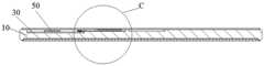
图1是本申请实施例的电子设备的爆炸图;1 is an exploded view of an electronic device according to an embodiment of the present application;
图2是本申请实施例的电子设备按压的结构示意图;2 is a schematic structural diagram of an electronic device pressing according to an embodiment of the present application;
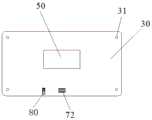
图3是本申请实施例的电子设备的一个视角的结构示意图;3 is a schematic structural diagram of an electronic device according to an embodiment of the present application from a perspective;
图4是图3中A-A线的剖视图之一,其中,按压区未受到按压;Figure 4 is one of the cross-sectional views taken along the line A-A in Figure 3, wherein the pressing area is not pressed;
图5是图4中圈示的C处的放大图;Fig. 5 is the enlarged view of the place C circled in Fig. 4;
图6是图3中A-A线的剖视图之二,其中,按压区受到按压;Fig. 6 is the second sectional view of line A-A in Fig. 3, wherein the pressing area is pressed;
图7是图6中圈示的D处的放大图;Figure 7 is an enlarged view of the D place circled in Figure 6;
图8是本申请实施例的电子设备的后盖一个表面的结构示意图;8 is a schematic structural diagram of one surface of a back cover of an electronic device according to an embodiment of the present application;
图9是本申请实施例的电子设备的第一电路板的一个视角的结构示意图;9 is a schematic structural diagram of a first circuit board of an electronic device according to an embodiment of the present application from a perspective;
图10是图3中B-B线的剖视图;Fig. 10 is a sectional view of line B-B in Fig. 3;
图11是图10中圈示的E处的放大图;Figure 11 is an enlarged view of the place E circled in Figure 10;
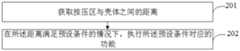
图12是本申请实施例的电子设备的控制方法的步骤流程图;12 is a flowchart of steps of a control method for an electronic device according to an embodiment of the present application;
图13是本申请实施例的电子设备的控制装置的结构框图;13 is a structural block diagram of a control device of an electronic device according to an embodiment of the present application;
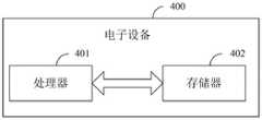
图14是本申请实施例的一种电子设备的结构示意图;14 is a schematic structural diagram of an electronic device according to an embodiment of the present application;
图15是本申请实施例的一种电子设备的硬件结构示意图。FIG. 15 is a schematic diagram of a hardware structure of an electronic device according to an embodiment of the present application.
附图标记:Reference number:
10-壳体,11-主板上盖,110-第一安装槽,111-第二安装槽,12-中框,13-第二螺纹孔,20-后盖,21-按压区,30-第一电路板,31-第一螺纹孔,41-距离检测器,410-定极片,411-动极片,4110-导电触片,4111-接触部,4112-连通部,50-处理器,60-第二电路板,70-连接器,71-公连接器,72-母连接器,80-弹片,81-固定部,82-接触部,90-粘贴层。10-Case, 11-Mainboard upper cover, 110-First installation slot, 111-Second installation slot, 12-Middle frame, 13-Second threaded hole, 20-Back cover, 21-Press area, 30-Part A circuit board, 31-first threaded hole, 41-distance detector, 410-stationary piece, 411-moving pole piece, 4110-conductive contact piece, 4111-contact part, 4112-connection part, 50-processor, 60-second circuit board, 70-connector, 71-male connector, 72-female connector, 80-spring piece, 81-fixed part, 82-contact part, 90-adhesive layer.
具体实施方式Detailed ways
下面将详细描述本申请的实施例,所述实施例的示例在附图中示出,其中自始至终相同或类似的标号表示相同或类似的元件或具有相同或类似功能的元件。下面通过参考附图描述的实施例是示例性的,仅用于解释本申请,而不能理解为对本申请的限制。基于本申请中的实施例,本领域普通技术人员在没有作出创造性劳动前提下所获得的所有其他实施例,都属于本申请保护的范围。The following will describe in detail the embodiments of the present application, examples of which are illustrated in the accompanying drawings, wherein the same or similar reference numerals refer to the same or similar elements or elements having the same or similar functions throughout. The embodiments described below with reference to the accompanying drawings are exemplary and are only used to explain the present application, but should not be construed as a limitation on the present application. Based on the embodiments in the present application, all other embodiments obtained by those of ordinary skill in the art without creative work fall within the protection scope of the present application.
本申请的说明书和权利要求书中的术语“第一”、“第二”的特征可以明示或者隐含地包括一个或者更多个该特征。在本申请的描述中,除非另有说明,“多个”的含义是两个或两个以上。此外,说明书以及权利要求中“和/或”表示所连接对象的至少其中之一,字符“/”,一般表示前后关联对象是一种“或”的关系。The features of the terms "first" and "second" in the description and claims of this application may expressly or implicitly include one or more of such features. In the description of this application, unless stated otherwise, "plurality" means two or more. In addition, "and/or" in the description and claims indicates at least one of the connected objects, and the character "/" generally indicates that the associated objects are in an "or" relationship.
在本申请的描述中,需要理解的是,术语“中心”、“纵向”、“横向”、“长度”、“宽度”、“厚度”、“上”、“下”、“前”、“后”、“左”、“右”、“竖直”、“水平”、“顶”、“底”“内”、“外”、“顺时针”、“逆时针”、“轴向”、“径向”、“周向”等指示的方位或位置关系为基于附图所示的方位或位置关系,仅是为了便于描述本申请和简化描述,而不是指示或暗示所指的装置或元件必须具有特定的方位、以特定的方位构造和操作,因此不能理解为对本申请的限制。In the description of this application, it should be understood that the terms "center", "longitudinal", "lateral", "length", "width", "thickness", "upper", "lower", "front", " Rear, Left, Right, Vertical, Horizontal, Top, Bottom, Inner, Outer, Clockwise, Counterclockwise, Axial, The orientations or positional relationships indicated by "radial direction", "circumferential direction", etc. are based on the orientations or positional relationships shown in the accompanying drawings, which are only for the convenience of describing the present application and simplifying the description, rather than indicating or implying the indicated devices or elements. It must have a specific orientation, be constructed and operate in a specific orientation, and therefore should not be construed as a limitation of the present application.
在本申请的描述中,需要说明的是,除非另有明确的规定和限定,术语“安装”、“相连”、“连接”应做广义理解,例如,可以是固定连接,也可以是可拆卸连接,或一体地连接;可以是机械连接,也可以是电连接;可以是直接相连,也可以通过中间媒介间接相连,可以是两个元件内部的连通。对于本领域的普通技术人员而言,可以具体情况理解上述术语在本申请中的具体含义。In the description of this application, it should be noted that, unless otherwise expressly specified and limited, the terms "installed", "connected" and "connected" should be understood in a broad sense, for example, it may be a fixed connection or a detachable connection Connection, or integral connection; can be mechanical connection, can also be electrical connection; can be directly connected, can also be indirectly connected through an intermediate medium, can be internal communication between two elements. For those of ordinary skill in the art, the specific meanings of the above terms in this application can be understood in specific situations.
下面结合附图,通过具体的实施例及其应用场景对本申请提供的电子设备进行详细地说明。The electronic device provided by the present application will be described in detail below through specific embodiments and application scenarios with reference to the accompanying drawings.
参照图1至7,图1示出了本申请实施例的电子设备的爆炸图,图2示出了本申请实施例的电子设备按压结构示意图,图3示出了本申请实施例的电子设备的一个视角的结构示意图,图4示出了图3中A-A线的剖视图之一,其中,按压区未受到按压,图5示出了图4中圈示的C处的放大图,图6示出了图3中A-A线的剖视图之二,其中,按压区受到按压,图7示出了是图6中圈示的D处的放大图。1 to 7 , FIG. 1 shows an exploded view of an electronic device according to an embodiment of the present application, FIG. 2 shows a schematic diagram of a pressing structure of an electronic device according to an embodiment of the present application, and FIG. 3 shows an electronic device according to an embodiment of the present application. A schematic view of the structure from a viewing angle, FIG. 4 shows one of the cross-sectional views of the A-A line in FIG. 3, wherein the pressing area is not pressed, FIG. 5 shows the enlarged view of the C circled in FIG. The second cross-sectional view of the line A-A in FIG. 3 is shown, wherein the pressing area is pressed, and FIG. 7 shows an enlarged view of the point D circled in FIG. 6 .
所述电子设备具体可以包括:壳体10、后盖20、距离检测器41以及处理器50;其中,后盖20安装于壳体10,距离检测器41设置于壳体10内;后盖20在与距离检测器41相对的位置设有按压区21,按压区21与壳体10之间形成第一间隙,在按压区21受到按压的情况下,按压区21与壳体10的距离发生改变,距离检测器41用于获取上述距离;处理器50设置于壳体10内,且与距离检测器41电连接,处理器50用于,在距离满足预设条件的情况下,执行预设条件对应的功能。与在先技术相比,本申请取消了按键,实现按键功能的部件均设置于电子设备的内部,,避免了在电子设备的侧边开槽,不仅利于电子设备继续向轻薄化发展,还可以提高电子设备的密封性,从而提高电子设备的防水性和防尘性。The electronic device may specifically include: a
具体而言,如图1至图3所示,后盖20安装于壳体10,距离检测器41设置于壳体内,后盖20在与距离检测器41相对的位置设有按压区21,按压区21与壳体之间形成第一间隙。如图4至图7所示,在按压区21受到按压的情况下后,后盖20会发生形变,按压区21与壳体10(壳体10与后盖20相对的表面)之间的距离发生改变。Specifically, as shown in FIG. 1 to FIG. 3 , the
具体而言,距离检测器41可以获取按压区21与壳体10之间的距离,由于处理器50与距离检测器41电连接,这样,处理器50会将接收到的距离值与预设条件进行对比,其中,预设条件为按压区21与壳体10之间的预设距离值。在该距离满足预设条件的情况下,也即,在该距离满足预设距离值的情况下,处理器50可以执行预设条件对应的功能。Specifically, the
在先技术中,若在电子设备的侧边设置用于放置按键的防放置槽,放置槽处的材料需要被挖掉,这样,就会降低电子设备侧边的强度,从而降低整机的强度,并且,还会影响整机的完整性和美观性。本申请与在先技术相比,通过取消常规的按键,而将可以实现按键的部件均设置于电子设备内部,这样,避免了在电子设备的侧边开槽,并且在不破坏整机完整性、不降低整机强度、不影响整机完整性的前提下,可以实现按压装置对应的功能。另外,从图2中可以看出,用户握持电子设备后,可以通过一根手指按压按压区21,即可实现预设条件(也即在先技术常规按键)对应的功能,操作十分方便,提高了用户的使用体验。In the prior art, if an anti-placement groove for placing buttons is provided on the side of the electronic device, the material at the placement groove needs to be dug out, which will reduce the strength of the side of the electronic device, thereby reducing the strength of the whole machine , and it will also affect the integrity and aesthetics of the whole machine. Compared with the prior art, the present application eliminates the conventional keys, and disposes the components that can realize the keys inside the electronic device, thus avoiding the slotting on the side of the electronic device, and without destroying the integrity of the whole machine , Under the premise of not reducing the strength of the whole machine and not affecting the integrity of the whole machine, the corresponding functions of the pressing device can be realized. In addition, it can be seen from FIG. 2 that after holding the electronic device, the user can press the
需要说明的是,上述处理器50执行的功能可以为锁屏、音量增大、音量降低和开关机等,具体的功能可以根据实际需求进行设定,本实施例对此可以不做限定。为了便于理解,本实施例以音量增大为例进行说明,本实施例可以在处理器50中预先存储预设距离值D与音量增量的对应关系,当处理器50接收到距离值时,查询对应关系中是否存在该距离值,若存在,基于该对应关系,确定与该距离值对应的音量增量,并给电子设备当前的音量增加该音量增量,以实现音量增大的目的。It should be noted that the functions performed by the
还需要说明的是,对于距离检测器41的设置数目,本实施例可以不做限定,具体可以根据用户的需求进行设定,每一个距离检测器41可以对应一种功能或多种功能,由于每一个距离检测器41的设置方式相同,本实施例图示中仅示出了一种距离检测器41,其他的距离检测器41参照设置即可。It should also be noted that the number of
可选的,为了方便用户找到按压区21的位置,本实施例可以在各按压区21的位置设置标识,并且,为了提高电子设备的美观性,可以将标识设置为卡通图案、艺术文字、图案与文字结合等形式,本实施例对标识的具体实现形式可以不做限定,具体可以根据用户的实际需求和处理器50执行的具体功能进行设定。Optionally, in order to facilitate the user to find the position of the
在本申请的实施例中,如图1、图4至图7所示,距离检测器41具体可以包括:动极片411、定极片410和检测单元;参照图8,图8示出了本申请实施例的电子设备的后盖20一个表面的结构示意图,动极片411连接于后盖20靠近壳体10的表面,且与按压区21相对;定极片410连接于壳体10,且与动极片411相对,距离为定极片410与动极片411之间的距离,距离与定极片410与动极片411之间的电容值相关;检测单元分别与动极片411和定极片410电连接,用于检测电容值;检测单元集成于处理器50,或者,处理器50与检测单元电连接,处理器50还用于,在电容值满足预设电容条件的情况下,执行预设电容条件对应的功能。In the embodiment of the present application, as shown in FIG. 1 , FIG. 4 to FIG. 7 , the
具体而言,如图8所示,动极片411可以通过粘接的方式连接于后盖20靠近壳体10的表面,并且,动极片411设置于与按压区21相对的位置。如图1、图4至图7所示,定极片410连接于壳体10与后盖20相对的表面,并且,定极片410与动极片411相对设置。前文所述的按压区21与壳体10之间的距离具体指:定极片410与动极片411之间的距离d。由于定极片410与动极片411之间具有电容值,也就是说,定极片410和动极片411可以组成一个电容器,该电容器的电容值Cx=εS/d,其中,ε为定极片410与动极片411间介质的介电常数,S为定极片410与动极片411的正对面积,d为定极片410与动极片411之间的距离。在按压区21受到按压的情况下,ε和S不变,并且,ε和S为已知量,因此,定极片410与动极片411之间的电容值Cx是随着d的变化而改变的。如图5所示,在电子设备的按压区21未受到按压的情况下,定极片410与动极片411之间的距离可以设定为初始距离d0,d0也可以认为是电子设备出厂时定极片410与动极片411之间的距离,此时,d0对应的电容值为初始电容值C0;如图7所示,在电子设备的按压区21受到按压的情况下,后盖20发生了形变,定极片410与动极片411之间的距离d发生变化,此时,定极片410与动极片411之间的电容值Cx也就会随着d的变化而改变。由于检测单元分别与定极片410和动极片411电连接,检测单元用于检测定极片410与动极片411之间的电容值,也就是说,检测单元可以根据d的变化实时检测Cx。Specifically, as shown in FIG. 8 , the
需要说明的是,在实际应用中,由于定极片410不动,定极片410与动极片411之间的距离d的变化可以看成动极片411位移S的变化,也即,定极片410与动极片411之间的距离d可以相当于S,也就是说,处理器50中也可以预先存储S与音量增量的对应关系,其中,S为动极片411初始位置时的质心与动极片411变形后时的质心之间的距离。当处理器50接收到动极片411的位移时,查询对应关系中是否存在该位移,若存在,基于对应关系,确定与该位移对应的音量增量,并给电子设备当前的音量增加该音量增量。It should be noted that, in practical applications, since the fixed
还需要说明的是,按压区21的面积与动极片411和定极片410覆盖的面积相适配,也即,按压区21的面积可以根据动极片411和定极片410覆盖的面积进行设定,本实施例对于按压区21的具体面积可以不做限定。It should also be noted that the area of the
可选的,检测单元可以集成于处理器50,也即,检测单元可以看成处理器50中的一个单元,对于处理器50而言,其中的检测单元实时检测定极片410与动极片411之间的电容值,获取到电容值后,与预设电容条件进行对比,预设电容条件为定极片410与动极片411之间的预设电容值,在该电容值满足预设电容条件的情况下,也即,在电容值满足预设电容值的情况下,处理器50执行该预设电容条件对应的功能,需要说明的是,前文所述的预设条件包括预设电容条件。依然以处理器50执行的功能为音量增大为例进行说明,当检测单元检测到电容值后,处理器50根据预设电容值与音量增量之间的对应关系,查询该对应关系中是否存在该电容值,若存在,基于该对应关系,确定与该电容值对应的音量增量,并给电子设备当前的音量增加该音量增量。需要说明的是,预设电容值与音量增量的对应关系是预先存储于处理器50中的。Optionally, the detection unit can be integrated in the
可选的,处理器50可以与检测单元电连接,检测单元实时检测定极片410与动极片411之间的电容值,并将电容值发送给处理器50,处理器获取到电容值后,与预设电容条件进行对比,在电容值满足预设条件的情况下,执行预设电容条件对应的功能。依然以处理器50执行的功能为音量增大为例进行说明,当检测单元检测到电容值后,发送给处理器50,处理器50获取到电容值后,根据电容值与音量增量之间的对应关系,查询该对应关系中是否存在该电容值,若存在,基于该对应关系,确定与该电容值对应的音量增量,并给电子设备当前的音量增加该音量增量。Optionally, the
需要说明的是,距离检测器41还可以包括震动元器件,震动元器件与处理器电50连接,当处理器50获取到电容值后,与预设电容条件进行对比,在电容值满足预设条件的情况下,处理器50执行预设电容条件对应的功能,同时,驱动所述震动元器件产生振动,以提高用户的交互体验。其中,震动元器件可以为线性马达或转子马达,本实施例对此可以不做限定,具体可以根据实际需求进行设定。It should be noted that the
可选的,如图1、图5和图7所示,距离检测器41还包括:第一电路板30和第二电路板60;第一电路板30设置于壳体内,处理器50连接于第一电路板30;第二电路板60连接于壳体10,定极片410连接于第二电路板60靠近后盖20的表面,第二电路板60与第一电路板30电连接。Optionally, as shown in FIG. 1 , FIG. 5 and FIG. 7 , the
具体而言,如图1所示,第一电路板30设置于壳体10内,第一电路板30具体设置于壳体10与后盖20相对的表面,处理器50连接于第一电路板30,在实际应用中,一般可以通过SMT(Surface Mounted Technology,表面贴装技术)或者DIP(Dual Inline-pin Package,元器件封装方式)将处理器50集成于第一电路板30。Specifically, as shown in FIG. 1 , the
在实际应用中,电子设备内部设有多个电路板,每个电路板上集成有多个元器件,并且,电子设备内部也设有多个零部件,由于定极片410设置于按压区21相对的位置,在按压区21受到按压的情况下,为了避免可能损坏某一电路板上的元器件或者电子设备内的零部件,本实施例根据定极片410的具体形状和电子设备内的空间,在第一间隙内设置了一块第二电路板60,第二电路板60与定极片410的形状相适配。如图1、图5和图7所示,第二电路板60连接于壳体10与后盖20相对的表面,定极片410可以通过SMT或DIP固定于第二电路板60靠近后盖20的表面,由于第二电路板60与第一电路板30电连接,如果检测单元集成于处理器50,这样就可以使定极片410与处理器50电连接,如果检测单元与处理器50电连接,这样,定极片410就可以通过检测单元与处理器50电连接,从而使处理器50执行预设电容条件对应的功能。另外,由于电子设备内部的空间有限,为了便于第二电路板60可以根据电子设备内部的空间进行布置,第二电路板60优选柔性电路板,这样,第二电路板60的形状就可以根据动极片411的形状及位置进行灵活设定。In practical applications, there are multiple circuit boards inside the electronic device, each circuit board is integrated with multiple components, and there are also multiple components inside the electronic device, because the
进一步的,如图1、图3、图5和图6所示,距离检测器41还包括连接器70,第二电路板60通过连接器70与第一电路板30电连接。Further, as shown in FIGS. 1 , 3 , 5 and 6 , the
在实际应用中,连接器是电子设备中传输信号、接通电流的桥梁,两个电路板一般通过连接器进行连接,因此,如图1、图3、图5和图6所示,本实施例通过连接器70将第二电路板60与第一电路板30连接,这样,就可以使定极片410与处理器50进行电连接。当然,本实施例也可以通过连接线将第二电路板60与第一电路板30电连接,本实施例对于第二电路板60和第一电路板30具体采用哪种连接关系可以不做限定,具体可以根据实际情况进行设定。In practical applications, the connector is a bridge for transmitting signals and connecting current in electronic equipment, and two circuit boards are generally connected through the connector. Therefore, as shown in Figure 1, Figure 3, Figure 5 and Figure 6, this implementation For example, the
进一步的,由于板对板连接器(简称BTB)具有传输能力强、轻薄、无需焊接等优点,本实施例的连接器70可以选用BTB,BTB包括公连接器71与母连接器72,公连接器71与母连接器72插接配对使用。如图1和图9所示,本实施例可以将母连接器72固定于第一电路板30,如图5所示,可以将公连接器71固定于第二电路板60,通过公连接器71与母连接器72的配合,将第二电路板60与第一电路板30电连接,并且,BTB使第一电路板30和第二电路板60的连接为可拆卸连接,这样可以方便两个电路板后续的拆装与维修。需要说明的是,也可以将母连接器固定于第二电路板60,公连接器固定于第一电路板30,对于公连接器的和母连接器具体的设置位置可以不做限定,具体可以根据实际情况进行设定。Further, since the board-to-board connector (BTB for short) has the advantages of strong transmission capability, lightness and thinness, and no need for welding, the
进一步的,为了提高定极片410的安装稳定性,如图1所示,电子设备还包括粘贴层,粘贴层设置于第二电路板60与壳体之间,第二电路板60通过粘贴层与壳体固定连接。对于粘贴层,粘接介质可以采用化学胶或者双面胶,本实施例对此可以不做限定,具体可以根据实际情况进行选用。Further, in order to improve the installation stability of the
进一步的,参照图1、图10和图11,图10示出了图3中B-B线的剖视图,图11示出了图10中圈示的E处的放大图,距离检测器41还包括:弹片80和导电触片4110;弹片80固定设置于第一电路板30靠近后盖的表面,导电触片4110固定设置于动极片411靠近第一电路板30的表面,且与弹片相对,导电触片4110与弹片80接触,以使动极片411与第一电路板30电连接。Further, referring to Fig. 1, Fig. 10 and Fig. 11, Fig. 10 shows a cross-sectional view of line B-B in Fig. 3, Fig. 11 shows an enlarged view of the circled E in Fig. 10, and the
具体而言,如图1和图11所示,弹片80固定设置于第一电路板30靠近后盖的表面,弹片80具体的设置位置可以根据第一电路板上的空间进行灵活设定。如图8所示,导电触片4110固定设置于动极片411靠近第一电路板30的表面,且与弹片相对,该导电触片4110可以认为是本领域普通技术人员都知道的金手指,金手指可以作为信号的输入输出端口。在电子设备的按压区21未受到按压的情况下,可以认为是电子设备出厂时的状态和电子设备静置的状态,导电触片4110与弹片80接触后导通,这样,动极片411就可以与第一电路板30电连接,进而与处理器50电连接,以使处理器50可以执行预设电容条件对应的功能。Specifically, as shown in FIG. 1 and FIG. 11 , the
可选的,如图11所示,弹片80可以包括固定部81和接触部82,固定部81为平板状,固定部81固定连接于第一电路板30,接触部82一端与固定部81连接,另一端悬空设置,接触部82另一端与固定部81之间设有第二间隙,第二间隙用于向定极片410与动极片411之间的距离变化提供空间。弹片80的接触部82为依次连续的弧形部形成,与动极片411的导电触片4110进行接触的弧形部相对于固定部81为凸弧,对于该凸弧的的弧度可以根据导电触片4110的面积进行设定。需要说明的是,图11示出了在按压区21受到3种按压力的情况下,弹片80的接触部82处于不同的位置。在实际应用中,第二间隙随着按压力的大小而改变,对于第二间隙的大小,可以根据实际情况进行设定,例如,以处理器50执行的功能为音量增大为例,第二间隙可以根据音量增大到极限分贝时后盖20的变形程度进行设定。Optionally, as shown in FIG. 11 , the
可选的,如图1和图8所示,动极片411包括连接的接触部4111和连通部4112,导电触片4110设置于连通部4112靠近第一电路板30的表面。接触部4111和定极片410的形状和面积相同,其可以为圆形、长方形、正方形和菱形中的任一种,本实施例对于接触部4111和定极片410的形状可以不做限定,具体可以根据实际情况进行设定。并且,连通部4112的形状需要根据弹片80的位置进行设定,图8中示出的连通部4112为矩形,导电触片4110设置于连通部4112远离接触部4111的一端,需要说明的是,为了节省成本,连通部4112尽量做小,连通部4112的形状也可以为圆形、破浪形等,本实施例对此可以不做限定,具体的形状需要根据弹片80的具体设置位置进行设定。Optionally, as shown in FIG. 1 and FIG. 8 , the
在本申请的一种可选实施例中,如图1所示,壳体10具体可以包括主板上盖11和中框12;主板上盖11设置于中框12内,且与所述后盖20相对,后盖20覆盖于中框12外,第一间隙由后盖20和与主板上盖11形成;第一电路板30和第二电路板60分别连接于主板上盖11。In an optional embodiment of the present application, as shown in FIG. 1 , the
具体而言,如图1所示,主板上盖11设置于中框12内,主板上盖11的周向侧边缘与中框12的周向内侧边连接,主板上盖11与后盖20相对,后盖20覆盖于中框12外,前文所述的第一间隙具体为后盖20与主板上盖11所形成,也即,距离检测器41放置在后盖20与主板上盖11之间。并且,距离检测器41检测的距离具体为按压区21与主板上盖11之间的距离。Specifically, as shown in FIG. 1 , the mainboard
可选的,如图1所示,主板上盖11与后盖20相对的表面设有第一安装槽110和第二安装槽111;第一安装槽110与第一电路板30的形状相适配,第一电路板30嵌设于第一安装槽110内;第二安装槽111与第二电路板60的形状相适配,第二电路板60嵌设于第二安装槽111内。Optionally, as shown in FIG. 1 , a
具体而言,为了利于电子设备继续向轻薄化发展,如图1所示,本实施例在主板上盖11与后盖20相对的表面设有第一安装槽110和第二安装槽111,第一安装槽110与第一电路板30的形状相适配,第一电路板30嵌设于第一安装槽110内,第二安装槽111与第二电路板60的形状相适配,第二电路板60嵌设于第二安装槽111内,这样,就可以尽量减小第一间隙,从而减小整机的厚度,利于电子设备继续向轻薄化发展。Specifically, in order to facilitate the continuous development of light and thin electronic devices, as shown in FIG. 1 , in this embodiment, a
进一步的,为了提高第一电路板30的安装稳定性,并便于第一电路板30的拆装,当第一电路板30嵌设于第一安装槽110后,可以通过多个紧固件将第一电路板30与壳体10进行紧固连接。具体的,如图1所示,第一电路板30与主板上盖11对应设置第一螺纹孔31和第二螺纹孔13,一个紧固件依次穿设一个第一螺纹孔31和一个第二螺纹孔13,以将第一电路板30与壳体10进行紧固连接。需要说明的是,紧固件可以选用螺丝、螺钉和螺栓等,本实施例对于紧固件的具体选型可以不做限定,具体可以根据实际情况进行设定。Further, in order to improve the installation stability of the
可选的,距离检测器41可以为霍尔传感器、激光测距仪和红外测距仪中的至少一种。Optionally, the
具体而言,本实施例除了上文所述的距离检测器41外,还可以选用霍尔传感器、激光测距仪和红外测距仪中的任一种,对于霍尔传感器、激光测距仪或红外测距仪的检测原理,本领域普通技术人员都是已知的,这里不再详细描述。Specifically, in this embodiment, in addition to the
进一步的,为了使壳体10与按压区21之间距离的测量精度更高,根据权重分排可以将霍尔传感器、激光测距仪和红外测距仪中的任意两种进行结合,或者三种结合。以霍尔传感器和激光测距仪为例进行说明,霍尔传感器和激光测距仪分别与处理器50电连接,霍尔传感器仪检测的距离mx和激光测距检测的距离nx分别出发送给处理器50,处理器50根据预先存储的权重分配比例进行计算,例如,mx*50%+nx*50%,以算出的距离值为依据,与预设条件进行匹配,在其满足预设条件的情况下,处理器50执行预设条件对应的功能。当然,本实施例对于距离检测器41的具体类型不局限与上述距离的几种,还可以为本领域普通技术人员公知的其他距离检测器41,本实施对此可以不做限定,当然,对于权重的比例分配也可以不做限定,具体可以根据实际情况进行设定。Further, in order to make the measurement accuracy of the distance between the
需要说明的是,由于霍尔传感器具有精度高,体积小、重量轻、寿命长、安装方便和功耗小等优点,本实施例的距离检测器优选霍尔传感器。It should be noted that, since the Hall sensor has the advantages of high precision, small size, light weight, long life, convenient installation and low power consumption, the distance detector in this embodiment is preferably a Hall sensor.
需要说明的是,两个电路板上元器件之间的连接都是通过连接线进行连接的,该技术本领域普通技术人员都知道,此处不再赘述。It should be noted that the connections between the components on the two circuit boards are all connected by connecting wires, which are known to those skilled in the art, and will not be repeated here.
综上,本申请实施例所述的电子设备至少具有以下优势:To sum up, the electronic device described in the embodiments of the present application has at least the following advantages:
在本申请的实施例中,将距离检测器设置于壳体内,也即,距离检测器设置于电子设备的内部。后盖在与距离检测器相对的位置设有按压区,按压区与壳体之间形成第一间隙,在按压区受到按压的情况下,按压区与壳体的距离发生改变,距离检测器可以获取该距离,在该距离满足预设条件的情况下,处理器执行预设条件对应的功能。与在先技术相比,本申请取消了常规的按键,实现按键功能的部件均设置于电子设备的内部,这样,避免了在电子设备的侧边开槽,不仅利于电子设备继续向轻薄化发展,还可以提高电子设备的密封性,从而提高电子设备的防水性和防尘性。In the embodiment of the present application, the distance detector is arranged in the casing, that is, the distance detector is arranged inside the electronic device. The rear cover is provided with a pressing area at a position opposite to the distance detector, and a first gap is formed between the pressing area and the casing. When the pressing area is pressed, the distance between the pressing area and the casing changes, and the distance detector can The distance is acquired, and if the distance satisfies the preset condition, the processor executes the function corresponding to the preset condition. Compared with the prior art, the present application cancels the conventional buttons, and the components for realizing the button function are all arranged inside the electronic device, thus avoiding the need for grooving on the side of the electronic device, which is not only conducive to the continuous development of the electronic device towards lightness and thinness. , It can also improve the sealing performance of electronic equipment, thereby improving the waterproof and dustproof performance of electronic equipment.
本申请实施例还提供一种电子设备的控制方法,参照图12,图12示出了本申请实施例的电子设备的控制方法的步骤流程图,具体可以包括:An embodiment of the present application further provides a method for controlling an electronic device. Referring to FIG. 12 , FIG. 12 shows a flowchart of the steps of the control method for an electronic device according to an embodiment of the present application, which may specifically include:
步骤201:获取按压区与壳体之间的距离。Step 201: Obtain the distance between the pressing area and the casing.
在本申请实施例中,电子设备的处理器50获取按压区21与壳体10之间的距离,在实际应用中,参照图1,电子设备的壳体10包括中框12和主板上盖11,主板上盖11与后盖20相对,后盖20覆盖于中框12外,此处按压区21与壳体10之间的距离具体指按压区21与主板上盖11之间的距离。In the embodiment of the present application, the
步骤202:在所述距离满足预设条件的情况下,执行预设条件对应的功能。Step 202: In the case that the distance satisfies the preset condition, execute the function corresponding to the preset condition.
在本申请实施例中,如图1所示,距离检测器41设置于电子设备内部。与在先技术相比,取消了常规的按键,实现按键功能的部件均设置于电子设备的内部,这样,避免了在电子设备的侧边开槽,不仅利于电子设备继续向轻薄化发展,还可以提高电子设备的密封性,从而提高电子设备的防水性和防尘性。In the embodiment of the present application, as shown in FIG. 1 , the
在本申请实施例中,预设条件可以为按压区21与壳体10之间的预设距离值,预设条件可以提前存储于处理器50中。当处理器50获取到按压区21与壳体10之间的距离后,与预设距离值进行对比,若该距离与预设距离值对应,处理器50执行预设条件对应的功能。In this embodiment of the present application, the preset condition may be a preset distance value between the
需要说明的是,处理器50执行的功能可以为锁屏、音量增大、音量降低和开关机等,为了便于理解,本实施例以处理器50执行的功能为音量增大为例进行说明,本实施例可以在处理器50中预先存储预设距离值与音量增量的对应关系,当处理器50接收到距离值时,查询对应关系中是否存在该距离值,若存在,基于该对应关系,确定与该距离值对应的音量增量,并给电子设备当前的音量增加该音量增量,以实现音量增大的目的。It should be noted that the functions performed by the
在本申请实施例中,对于一个距离检测器41,不同的预设距离值可以对应不用的功能,例如,预设距离值包括第一预设值和第二预设值,第一预设值对应拍照功能,第二预设值对应录像功能,当处理器获取到按压区21与壳体10之间的距离后,与预设距离值进行对比,当获取的距离与第一预设值对应时,处理器50执行电子设备的拍照功能,当获取的距离与第二预设值对应时,处理器50执行的录像功能。需要说明的是,对应第一预设值和第二预设值对应的功能,不局限于举例的一种,还可以为截屏、投屏、开机、关机、锁屏等功能,本实施例对此可以不做限定,具体根据实际需求进行设定。In the embodiment of the present application, for a
在本申请实施例中,对于一个距离检测器41,不同的预设距离值结合按压的时长,对应不同的功能,例如,第三预设距离值和第一预设时长对应锁屏功能,第四预设距离值和第二预设时长对应开机功能。该种情况下,处理器50与按压区21电连接,在按压区21受到按压时,处理器50进行计时,若按压时长等于第三预设时长,触发电子设备的锁屏功能,若按压时长等于第四预设时长,处理器50执行电子设备的开机功能。需要说明的是,对应第一预设值和第二预设值对应的功能,不局限于举例的一种,还可以为截屏、投屏、关机、拍照、录像等功能,本实施例对此可以不做限定,具体根据实际需求进行设定。In the embodiment of the present application, for a
在本申请实施例中,一个距离检测器41还可以对应一组功能,例如,开关机,如果电子设备当前为关机状态,当处理器50获取到按压区21与壳体10之间的距离满足预设距离时,执行电子设备的开机功能,相反,如果电子设备当前为开机状态,当处理器50获取到按压区21与壳体10之间的距离满足预设距离时,执行电子设备的关机功能。In this embodiment of the present application, a
在本申请实施例中,所述步骤202包括子步骤:在所述电容值满足预设电容条件的情况下,执行预设电容条件对应的功能。In the embodiment of the present application, the
在本申请实施例中,如图1、图4至图8所示,定极片410连接于壳体10与后盖20相对的表面,也即,定极片410连接于主板上盖11,动极片连接于后盖与主板上盖相对的表面,并且,定极片410与动极片411相对设置。也即,定极片410和动极片411可以组成一个电容器,该电容器的电容值Cx=εS/d,其中,ε为定极片410与动极片411间介质的介电常数,S为定极片410与动极片411的正对面积,d为定极片410与动极片411之间的距离。前文所述的按压区21与壳体10之间的距离具体为定极片410与动极片411之间的距离d。在本实施例中中,由于ε和S不变,并且,ε和S为已知量,因此,定极片410与动极片411之间的电容值Cx仅与d相关,也即,电容值Cx与按压区21与壳体10之间的距离相关。这样,本实施例也可以以电容值作为处理器50执行预设条件对应的功能的条件。处理器50可以获取到定极片410与动极片411之间的电容值,上述实施例对此进行了详细的描述,此处不再赘述。In the embodiment of the present application, as shown in FIG. 1 , FIG. 4 to FIG. 8 , the
在本申请实施例中,可以在处理器50中预先存储预设电容条件,即为定极片410与动极片411之间的预设电容值。当处理器获取到定极片410与动极片411之间的电容值后,与预设电容值进行对比,若该电容值与预设距离值对应,则执行预设电容条件对应的功能。为了便于理解,依然以处理器50执行的功能为音量增大为例进行说明,处理器50根据预设电容值与音量增量之间的对应关系,查询该对应关系中是否存在该电容值,若存在,基于该对应关系,确定与该电容值对应的音量增量,并给电子设备当前的音量增加该音量增量。需要说明的是,预设电容值与音量增量的对应关系是预先存储于处理器50中的。In this embodiment of the present application, a preset capacitance condition may be pre-stored in the
在本申请实施例中,获取按压区与壳体之间的距离,在所述距离满足预设条件的情况下,执行预设条件对应的功能,可见,本实施例通过电子设备的控制方法执行预设条件对应的功能,由于本申请取消了常规的按键,实现按键功能的部件均设置于电子设备的内部,与在先技术相比,避免了在电子设备的侧边开槽,不仅利于电子设备继续向轻薄化发展,还可以提高电子设备的密封性,从而提高电子设备的防水性和防尘性。In the embodiment of the present application, the distance between the pressing area and the casing is obtained, and when the distance satisfies the preset condition, the function corresponding to the preset condition is executed. It can be seen that this embodiment is executed by the control method of the electronic device. For the function corresponding to the preset condition, since the application cancels the conventional button, the components for realizing the button function are all arranged inside the electronic device. As the device continues to develop towards thinness and lightness, the sealing performance of the electronic device can also be improved, thereby improving the waterproof and dustproof performance of the electronic device.
本申请实施例还提供一种电子设备的控制装置,参照图13,图13示出了本申请实施例的电子设备的控制装置的结构框图,所述控制装置300具体可以包括:An embodiment of the present application further provides a control apparatus for an electronic device. Referring to FIG. 13 , FIG. 13 shows a structural block diagram of the control apparatus for an electronic device according to an embodiment of the present application. The
距离获取模块301,用于获取按压区与壳体之间的距离。The
功能执行模块302,用于在所述距离满足预设条件的情况下,触发预设条件对应的功能。The
本申请实施例的电子设备的控制装置用于实现前述相应的电子设备的控制方法,并具有与方法实施例相应的有益效果,在此不再赘述。The control apparatus for an electronic device according to the embodiment of the present application is used to implement the corresponding control method for the electronic device, and has the beneficial effects corresponding to the method embodiments, which will not be repeated here.
可选的,参照图14所示,图14示出了本申请实施例的一种电子设备的结构示意图。Optionally, referring to FIG. 14 , FIG. 14 shows a schematic structural diagram of an electronic device according to an embodiment of the present application.
本申请实施例还提供了一种电子设备400,包括处理器401,存储器402及存储在存储器402上并可在处理器401上运行的程序或指令,程序或指令被处理器401执行时实现上述的控制方法的各个过程,且能达到相同的技术效果,为避免重复,这里不再赘述。The embodiment of the present application also provides an
需要说明的是,本申请实施例中的电子设备包括移动电子设备和非移动电子设备。It should be noted that the electronic devices in the embodiments of the present application include mobile electronic devices and non-mobile electronic devices.
参照图15,图15示出了本申请实施例的一种电子设备的硬件结构示意图。Referring to FIG. 15 , FIG. 15 shows a schematic diagram of a hardware structure of an electronic device according to an embodiment of the present application.
该电子设备500包括但不限于:射频单元501、网络模块502、音频输出单元503、输入单元504、传感器505、显示单元506、用户输入单元507、接口单元508、存储器509、以及处理器510等部件。The
本领域技术人员可以理解,电子设备400还可以包括给各个部件供电的电源(比如电池),电源可以通过电源管理系统与处理器110逻辑相连,从而通过电源管理系统实现管理充电、放电、以及功耗管理等功能。图14中示出的电子设备结构并不构成对电子设备的限定,电子设备可以包括比图示更多或更少的部件,或者组合某些部件,或者不同的部件布置,在此不再赘述。Those skilled in the art can understand that the
其中,处理器510,用于获取按压区与壳体之间的距离,在所述距离满足预设条件的情况下,执行预设条件对应的功能。The
在本申请实施例中,获取按压区与壳体之间的距离,在所述距离满足预设条件的情况下,执行预设条件对应的功能,可见,本实施例取消了常规的按键,实现按键功能的部件均设置于电子设备的内部,与在先技术相比,避免了在电子设备的侧边开槽,不仅利于电子设备继续向轻薄化发展,还可以提高电子设备的密封性,从而提高电子设备的防水性和防尘性。In the embodiment of the present application, the distance between the pressing area and the housing is obtained, and when the distance satisfies the preset condition, the function corresponding to the preset condition is executed. It can be seen that this embodiment cancels the conventional button, and realizes the The components of the button function are all arranged inside the electronic device. Compared with the prior art, it is avoided to make a slot on the side of the electronic device. Improve the water and dust resistance of electronic equipment.
应理解的是,本申请实施例中,输入单元504可以包括图形处理器(GraphicsProcessing Unit,GPU)5041和麦克风5042,图形处理器5041对在视频捕获模式或图像捕获模式中由图像捕获装置(如摄像头)获得的静态图片或视频的图像数据进行处理。显示单元506可包括显示面板5061,可以采用液晶显示器、有机发光二极管等形式来配置显示面板5061。用户输入单元507包括触控面板5071以及其他输入设备5072。触控面板5071,也称为触摸屏。触控面板5071可包括触摸检测装置和触摸控制器两个部分。其他输入设备5072可以包括但不限于物理键盘、功能键(比如音量控制按键、开关按键等)、轨迹球、鼠标、操作杆,在此不再赘述。存储器509可用于存储软件程序以及各种数据,包括但不限于应用程序和操作系统。处理器510可集成应用处理器和调制解调处理器,其中,应用处理器主要处理操作系统、用户界面和应用程序等,调制解调处理器主要处理无线通信。可以理解的是,上述调制解调处理器也可以不集成到处理器510中。It should be understood that, in this embodiment of the present application, the
本申请实施例还提供一种可读存储介质,所述可读存储介质上存储有程序或指令,该程序或指令被处理器执行时实现上述电子设备的控制方法实施例的各个过程,且能达到相同的技术效果,为避免重复,这里不再赘述。The embodiments of the present application further provide a readable storage medium, where a program or an instruction is stored on the readable storage medium, and when the program or instruction is executed by a processor, each process of the above-mentioned embodiment of the control method for an electronic device is implemented, and can To achieve the same technical effect, in order to avoid repetition, details are not repeated here.
其中,所述处理器为上述实施例中所述的电子设备中的处理器。所述可读存储介质,包括计算机可读存储介质,如计算机只读存储器(Read-Only Memory,ROM)、随机存取存储器(Random Access Memory,RAM)、磁碟或者光盘等。Wherein, the processor is the processor in the electronic device described in the foregoing embodiments. The readable storage medium includes a computer-readable storage medium, such as a computer read-only memory (Read-Only Memory, ROM), a random access memory (Random Access Memory, RAM), a magnetic disk or an optical disk, and the like.
在本申请说明书的描述中,参考术语“一个实施例”、“一些实施例”、“示意性实施例”、“示例”、“具体示例”、或“一些示例”等的描述意指结合该实施例或示例描述的具体特征、结构、材料或者特点包含于本申请的至少一个实施例或示例中。在本说明书中,对上述术语的示意性表述不一定指的是相同的实施例或示例。而且,描述的具体特征、结构、材料或者特点可以在任何的一个或多个实施例或示例中以合适的方式结合。In the description of this specification, reference to the terms "one embodiment," "some embodiments," "exemplary embodiment," "example," "specific example," or "some examples", etc. A particular feature, structure, material, or characteristic described by an embodiment or example is included in at least one embodiment or example of the present application. In this specification, schematic representations of the above terms do not necessarily refer to the same embodiment or example. Furthermore, the particular features, structures, materials or characteristics described may be combined in any suitable manner in any one or more embodiments or examples.
需要说明的是,在本申请说明书的描述中,术语“包括”、“包含”或者其任何其他变体意在涵盖非排他性的包含,从而使得包括一系列要素的过程、方法、物品或者装置不仅包括那些要素,而且还包括没有明确列出的其他要素,或者是还包括为这种过程、方法、物品或者装置所固有的要素。在没有更多限制的情况下,由语句“包括一个……”限定的要素,并不排除在包括该要素的过程、方法、物品或者装置中还存在另外的相同要素。此外,需要指出的是,本申请实施方式中的方法和装置的范围不限按示出或讨论的顺序来执行功能,还可包括根据所涉及的功能按基本同时的方式或按相反的顺序来执行功能,例如,可以按不同于所描述的次序来执行所描述的方法,并且还可以添加、省去、或组合各种步骤。另外,参照某些示例所描述的特征可在其他示例中被组合。It should be noted that in the description of the specification of the present application, the terms "comprising", "comprising" or any other variations thereof are intended to cover non-exclusive inclusion, such that a process, method, article or device comprising a series of elements not only Those elements are included, but also other elements not expressly listed or inherent to such a process, method, article or apparatus. Without further limitation, an element qualified by the phrase "comprising a..." does not preclude the presence of additional identical elements in a process, method, article or apparatus that includes the element. Furthermore, it should be noted that the scope of the methods and apparatus in the embodiments of the present application is not limited to performing the functions in the order shown or discussed, but may also include performing the functions in a substantially simultaneous manner or in the reverse order depending on the functions involved. To perform functions, for example, the described methods may be performed in an order different from that described, and various steps may also be added, omitted, or combined. Additionally, features described with reference to some examples may be combined in other examples.
通过以上的实施方式的描述,本领域的技术人员可以清楚地了解到上述实施例方法可借助软件加必需的通用硬件平台的方式来实现,当然也可以通过硬件,但很多情况下前者是更佳的实施方式。基于这样的理解,本申请的技术方案本质上或者说对现有技术做出贡献的部分可以以计算机软件产品的形式体现出来,该计算机软件产品存储在一个存储介质(如ROM/RAM、磁碟、光盘)中,包括若干指令用以使得一台终端(可以是手机,计算机,服务器,或者网络设备等)执行本申请各个实施例所述的方法。From the description of the above embodiments, those skilled in the art can clearly understand that the method of the above embodiment can be implemented by means of software plus a necessary general hardware platform, and of course can also be implemented by hardware, but in many cases the former is better implementation. Based on this understanding, the technical solutions of the present application can be embodied in the form of computer software products that are essentially or contribute to the prior art, and the computer software products are stored in a storage medium (such as ROM/RAM, magnetic disk , CD), including several instructions to make a terminal (which may be a mobile phone, a computer, a server, or a network device, etc.) execute the methods described in the various embodiments of the present application.
尽管已经示出和描述了本申请的实施例,本领域的普通技术人员可以理解:在不脱离本申请的原理和宗旨的情况下可以对这些实施例进行多种变化、修改、替换和变型,本申请的范围由权利要求及其等同物限定。Although the embodiments of the present application have been shown and described, it will be understood by those of ordinary skill in the art that various changes, modifications, substitutions and alterations can be made in these embodiments without departing from the principles and spirit of the present application, The scope of the application is defined by the claims and their equivalents.
Claims (10)
Translated fromChinesePriority Applications (1)
| Application Number | Priority Date | Filing Date | Title |
|---|---|---|---|
| CN202110427076.2ACN113131916B (en) | 2021-04-20 | 2021-04-20 | Electronic device, control method and control device of electronic device |
Applications Claiming Priority (1)
| Application Number | Priority Date | Filing Date | Title |
|---|---|---|---|
| CN202110427076.2ACN113131916B (en) | 2021-04-20 | 2021-04-20 | Electronic device, control method and control device of electronic device |
Publications (2)
| Publication Number | Publication Date |
|---|---|
| CN113131916Atrue CN113131916A (en) | 2021-07-16 |
| CN113131916B CN113131916B (en) | 2024-09-24 |
Family
ID=76778497
Family Applications (1)
| Application Number | Title | Priority Date | Filing Date |
|---|---|---|---|
| CN202110427076.2AActiveCN113131916B (en) | 2021-04-20 | 2021-04-20 | Electronic device, control method and control device of electronic device |
Country Status (1)
| Country | Link |
|---|---|
| CN (1) | CN113131916B (en) |
Cited By (1)
| Publication number | Priority date | Publication date | Assignee | Title |
|---|---|---|---|---|
| CN113645354A (en)* | 2021-08-05 | 2021-11-12 | Oppo广东移动通信有限公司 | Electronic device |
Citations (7)
| Publication number | Priority date | Publication date | Assignee | Title |
|---|---|---|---|---|
| US8643628B1 (en)* | 2012-10-14 | 2014-02-04 | Neonode Inc. | Light-based proximity detection system and user interface |
| CN105592207A (en)* | 2014-10-22 | 2016-05-18 | 中兴通讯股份有限公司 | Anti-theft method for mobile terminal and corresponding mobile terminal |
| CN106569648A (en)* | 2016-10-31 | 2017-04-19 | 努比亚技术有限公司 | Mobile equipment and mobile equipment control method |
| CN207264361U (en)* | 2017-10-25 | 2018-04-20 | 信利光电股份有限公司 | A kind of rear cover and electronic equipment |
| CN108616616A (en)* | 2018-04-03 | 2018-10-02 | 北京小米移动软件有限公司 | Mobile terminal |
| CN110597448A (en)* | 2019-09-09 | 2019-12-20 | Oppo广东移动通信有限公司 | Electronic equipment and control method thereof |
| CN212519062U (en)* | 2019-05-30 | 2021-02-09 | 华为技术有限公司 | a mobile terminal |
- 2021
- 2021-04-20CNCN202110427076.2Apatent/CN113131916B/enactiveActive
Patent Citations (7)
| Publication number | Priority date | Publication date | Assignee | Title |
|---|---|---|---|---|
| US8643628B1 (en)* | 2012-10-14 | 2014-02-04 | Neonode Inc. | Light-based proximity detection system and user interface |
| CN105592207A (en)* | 2014-10-22 | 2016-05-18 | 中兴通讯股份有限公司 | Anti-theft method for mobile terminal and corresponding mobile terminal |
| CN106569648A (en)* | 2016-10-31 | 2017-04-19 | 努比亚技术有限公司 | Mobile equipment and mobile equipment control method |
| CN207264361U (en)* | 2017-10-25 | 2018-04-20 | 信利光电股份有限公司 | A kind of rear cover and electronic equipment |
| CN108616616A (en)* | 2018-04-03 | 2018-10-02 | 北京小米移动软件有限公司 | Mobile terminal |
| CN212519062U (en)* | 2019-05-30 | 2021-02-09 | 华为技术有限公司 | a mobile terminal |
| CN110597448A (en)* | 2019-09-09 | 2019-12-20 | Oppo广东移动通信有限公司 | Electronic equipment and control method thereof |
Cited By (2)
| Publication number | Priority date | Publication date | Assignee | Title |
|---|---|---|---|---|
| CN113645354A (en)* | 2021-08-05 | 2021-11-12 | Oppo广东移动通信有限公司 | Electronic device |
| CN113645354B (en)* | 2021-08-05 | 2023-04-07 | Oppo广东移动通信有限公司 | Electronic device |
Also Published As
| Publication number | Publication date |
|---|---|
| CN113131916B (en) | 2024-09-24 |
Similar Documents
| Publication | Publication Date | Title |
|---|---|---|
| CN111212209B (en) | Camera module and electronic equipment | |
| EP4156705B1 (en) | Electronic device including pop-up and rotational camera | |
| US11507143B2 (en) | Electronic device including a plurality of displays and method for operating same | |
| CN107483692A (en) | Cover assembly, casing assembly, processing method of casing assembly, and mobile terminal | |
| KR20190101605A (en) | Electronic device including movable flexible display | |
| US20220311846A1 (en) | Electronic device including a plurality of displays and method for operating same | |
| CN110472399B (en) | Electronic equipment and control method thereof | |
| CN112578461B (en) | Key detection device and electronic equipment | |
| JP2008225648A (en) | Power source controller and electronic equipment equipped with the same, and method for starting electronic equipment | |
| CN111614805A (en) | electronic device | |
| CN206349981U (en) | A kind of key of pressure sensor component and electronic equipment | |
| CN110456940A (en) | Electronic device and control method thereof | |
| CN108055363B (en) | Electronic equipment | |
| CN113131916A (en) | Electronic device, control method and control device of electronic device | |
| CN108563393A (en) | Equipment parameter adjusting method and device, storage medium and electronic equipment | |
| US20160370910A1 (en) | Electronic device including a touch pad | |
| CN110286805A (en) | Electronic equipment and control method thereof | |
| CN110138943A (en) | Electronic equipment and control method of camera | |
| WO2019095100A1 (en) | Side key device and electronic terminal | |
| CN110262699A (en) | Electronic equipment and its control method | |
| CN110149439A (en) | Shell assembly, electronic equipment and control method thereof | |
| CN110297565A (en) | The control method of electronic equipment and touch control component | |
| CN210778308U (en) | Electronic device | |
| EP3370398B1 (en) | Shell assembly, electronic device and mobile phone having same | |
| CN108228059B (en) | Portable electronic device and sensing method thereof |
Legal Events
| Date | Code | Title | Description |
|---|---|---|---|
| PB01 | Publication | ||
| PB01 | Publication | ||
| SE01 | Entry into force of request for substantive examination | ||
| SE01 | Entry into force of request for substantive examination | ||
| GR01 | Patent grant | ||
| GR01 | Patent grant |