CN113131789B - A multi-modal road piezoelectric generator - Google Patents
A multi-modal road piezoelectric generatorDownload PDFInfo
- Publication number
- CN113131789B CN113131789BCN202110433246.8ACN202110433246ACN113131789BCN 113131789 BCN113131789 BCN 113131789BCN 202110433246 ACN202110433246 ACN 202110433246ACN 113131789 BCN113131789 BCN 113131789B
- Authority
- CN
- China
- Prior art keywords
- power generation
- generation unit
- chuck
- connecting rod
- shell
- Prior art date
- Legal status (The legal status is an assumption and is not a legal conclusion. Google has not performed a legal analysis and makes no representation as to the accuracy of the status listed.)
- Active
Links
- 238000010248power generationMethods0.000claimsabstractdescription75
- 230000001050lubricating effectEffects0.000claimsdescription3
- 238000010008shearingMethods0.000claimsdescription3
- 239000000126substanceSubstances0.000claimsdescription3
- 238000010586diagramMethods0.000description6
- 230000005611electricityEffects0.000description3
- 239000011159matrix materialSubstances0.000description2
- 239000000758substrateSubstances0.000description2
- 238000010276constructionMethods0.000description1
- 230000007812deficiencyEffects0.000description1
- 230000000694effectsEffects0.000description1
- 230000007613environmental effectEffects0.000description1
- 238000009434installationMethods0.000description1
- 230000000670limiting effectEffects0.000description1
- 238000000034methodMethods0.000description1
- 230000001737promoting effectEffects0.000description1
- 230000005855radiationEffects0.000description1
Images


Classifications
- H—ELECTRICITY
- H02—GENERATION; CONVERSION OR DISTRIBUTION OF ELECTRIC POWER
- H02N—ELECTRIC MACHINES NOT OTHERWISE PROVIDED FOR
- H02N2/00—Electric machines in general using piezoelectric effect, electrostriction or magnetostriction
- H02N2/18—Electric machines in general using piezoelectric effect, electrostriction or magnetostriction producing electrical output from mechanical input, e.g. generators
- H02N2/186—Vibration harvesters
Landscapes
- General Electrical Machinery Utilizing Piezoelectricity, Electrostriction Or Magnetostriction (AREA)
Abstract
Description
Translated fromChinese技术领域technical field
本发明涉及一种多模态道路压电发电装置,属于压电发电的技术领域。The invention relates to a multi-modal road piezoelectric power generation device, which belongs to the technical field of piezoelectric power generation.
技术背景technical background
道路作为最主要的交通设施,对促进经济发展和为人们生产生活提供便利起到了重要作用。改革开放以来,经济的飞速发展,促进了运输需求的持续增长,为道路工程建设的发展提供了千载难逢的机遇,同时也提高了对道路功能的要求。道路在承担交通运输功能的同时也承载着大量的环境能量,车辆轴载作用的振动能量、太阳辐射的能量、轮胎与路面的摩擦能量甚至是汽车发动机废气排出的能量均可以被回收利用,利用压电效应将道路上交通轴载振动产生的机械能转化为电能为道路交通附属设施供电是一种理想的道路环境能量收集方式。As the most important transportation facility, roads play an important role in promoting economic development and providing convenience for people's production and life. Since the reform and opening up, the rapid economic development has promoted the continuous growth of transportation demand, provided a once-in-a-lifetime opportunity for the development of road engineering construction, and also raised the requirements for road functions. The road also carries a large amount of environmental energy while undertaking the transportation function. The vibration energy of the vehicle axle load, the energy of solar radiation, the friction energy between the tire and the road surface, and even the energy discharged from the exhaust gas of the automobile engine can be recycled and utilized. The piezoelectric effect converts the mechanical energy generated by the axle-loaded vibration of the road into electrical energy to supply power to the road traffic ancillary facilities, which is an ideal way to collect energy from the road environment.
发明内容SUMMARY OF THE INVENTION
本发明针对现有技术的不足,提出了一种多模态道路压电发电装置。Aiming at the deficiencies of the prior art, the present invention proposes a multi-modal road piezoelectric generating device.
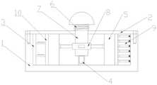
本发明采用的技术方案是:一种多模态道路压电发电装置,由壳体(1)、盘体(2)、d31发电单元(3)、d33发电单元悬臂梁(4)、滑块(5)、弹簧(6)、连杆(7)、卡盘(8)、d15发电单元(9)和弹性体(10)组成。The technical solution adopted in the present invention is: a multi-modal road piezoelectric power generation device, which is composed of a casing (1), a disk body (2), a d31 power generation unit (3), a d33 power generation unit cantilever beam (4), and a slider. (5), a spring (6), a connecting rod (7), a chuck (8), a d15 power generating unit (9) and an elastic body (10).
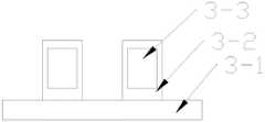
所述壳体(1)开设有螺纹孔(1-1),盘体(2)开设有螺纹孔(2-1)和圆孔(2-2),滑块(5)开设有滑道(5-1),连杆(7)开设有凹槽(7-1),卡盘(8)由磁铁(8-1)和连接球(8-2)组成,d15发电单元(9)是由短弹簧(9-1)、压电片(9-2)和剪切板(9-3)组成,d31发电单元(3)由薄板(3-1)、基板(3-2)和压电片(3-3)组成;所述连杆(7)与盘体(2)相配合,弹簧(6)套在连杆(7)上,卡盘(8)与连杆(7)的凹槽(7-1)相配合,卡盘(8)的连接球(8-2)与滑块(5)的滑道(5-1)相配合,弹性体(10)紧靠滑块(5)安装,d15发电单元(9)和d31发电单元(3)一端与弹性体(10)相配合另一端与壳体(1)相安装,d33发电单元悬臂梁(4)靠近卡盘(8)的磁铁(8-1)安装;最后壳体(1)与盘体(2)通过螺纹相配合,达到装配整个发电装置的目的。The casing (1) is provided with a threaded hole (1-1), the disc body (2) is provided with a threaded hole (2-1) and a circular hole (2-2), and the slider (5) is provided with a slideway ( 5-1), the connecting rod (7) is provided with a groove (7-1), the chuck (8) is composed of a magnet (8-1) and a connecting ball (8-2), and the d15 power generation unit (9) is composed of The short spring (9-1), the piezoelectric sheet (9-2) and the shearing plate (9-3) are composed, and the d31 power generation unit (3) is composed of the thin plate (3-1), the substrate (3-2) and the piezoelectric The connecting rod (7) is matched with the disc body (2), the spring (6) is sleeved on the connecting rod (7), the chuck (8) and the concave groove of the connecting rod (7) The groove (7-1) is matched, the connecting ball (8-2) of the chuck (8) is matched with the slideway (5-1) of the slider (5), and the elastic body (10) is close to the slider (5). ) installation, one end of the d15 power generation unit (9) and the d31 power generation unit (3) is matched with the elastic body (10) and the other end is installed with the casing (1), the cantilever beam (4) of the d33 power generation unit is close to the chuck (8) The magnet (8-1) is installed; finally, the casing (1) and the disc body (2) are matched with each other through threads, so as to achieve the purpose of assembling the entire power generating device.
作为上述技术方案的进一步改进,滑块(5)的滑道(5-1)的深度是与连接球(8-2)直径一样的四分之三圆,防止连接球(8-2)在滑动时脱轨。As a further improvement of the above technical solution, the depth of the slideway (5-1) of the slider (5) is three-quarters of a circle that is the same as the diameter of the connecting ball (8-2), preventing the connecting ball (8-2) from entering the Derailment while sliding.
作为上述技术方案的进一步改进,在滑块(5)的滑道(5-1)和壳体(1)涂有润滑物质有利于滑块(5)的滑动。As a further improvement of the above technical solution, the slideway (5-1) and the casing (1) of the slider (5) are coated with a lubricating substance to facilitate the sliding of the slider (5).
作为上述技术方案的进一步改进,d15发电单元(9)由多个发电组件矩阵排列而成,每个发电组件应紧密连接,提高d15发电单元(9)效率。As a further improvement of the above technical solution, the d15 power generation unit (9) is formed by a plurality of power generation components arranged in a matrix, and each power generation component should be closely connected to improve the efficiency of the d15 power generation unit (9).
作为上述技术方案的进一步改进,d33发电单元悬臂梁(4)应安装在卡盘(8)的斜下方,提高d33发电单元悬臂梁(4)效率。As a further improvement of the above technical solution, the cantilever beam (4) of the d33 power generation unit should be installed diagonally below the chuck (8) to improve the efficiency of the cantilever beam (4) of the d33 power generation unit.
附图说明Description of drawings
图1是本发明一个较佳实施例中俘能器的结构示意图。FIG. 1 is a schematic structural diagram of an energy harvester in a preferred embodiment of the present invention.
图2是本发明的一个爆炸示意图。Figure 2 is an exploded schematic diagram of the present invention.
图3是卡盘的示意图。Figure 3 is a schematic view of a chuck.
图4是滑块的示意图。Figure 4 is a schematic diagram of a slider.
图5是d15发电单元示意图。Figure 5 is a schematic diagram of the d15 power generation unit.
图6是d31发电单元示意图。Figure 6 is a schematic diagram of the d31 power generation unit.
图7是d33发电单元示意图。Figure 7 is a schematic diagram of the d33 power generation unit.
具体实施方案specific implementation
为了使本领域技术人员更好地理解本发明的技术方案,下面结合附图对本发明进行详细描述,本部分的描述仅是示范性和解释性,不应对本发明的保护范围有任何的限制作用。In order to make those skilled in the art better understand the technical solutions of the present invention, the present invention will be described in detail below with reference to the accompanying drawings. The description in this part is only exemplary and explanatory, and should not have any limiting effect on the protection scope of the present invention. .
请参阅图1~7,本发明实施例中,具体结构包括:Referring to FIGS. 1 to 7 , in the embodiment of the present invention, the specific structure includes:
一种多模态道路压电发电装置,由壳体(1)、盘体(2)、d31发电单元(3)、d33发电单元悬臂梁(4)、滑块(5)、弹簧(6)、连杆(7)、卡盘(8)、d15发电单元(9)和弹性体(10)组成;所述壳体(1)开设有螺纹孔(1-1),盘体(2)开设有螺纹孔(2-1)和圆孔(2-2),滑块(5)开设有滑道(5-1),连杆(7)开设有凹槽(7-1),卡盘(8)由磁铁(8-1)和连接球(8-2)组成,d15发电单元(9)是由短弹簧(9-1)、压电片(9-2)和剪切板(9-3)组成,d31发电单元(3)由薄板(3-1)、基板(3-2)和压电片(3-3)组成;所述连杆(7)与盘体(2)相配合,弹簧(6)套在连杆(7)上,卡盘(8)与连杆(7)的凹槽(7-1)相配合,卡盘(8)的连接球(8-2)与滑块(5)的滑道(5-1)相配合,弹性体(10)紧靠滑块(5)安装,d15发电单元(9)和d31发电单元(3)一端与弹性体(10)相配合另一端与壳体(1)相安装,d33发电单元悬臂梁(4)靠近卡盘(8)的磁铁(8-1)安装;最后壳体(1)与盘体(2)通过螺纹相配合,达到装配整个发电装置的目的。A multimodal road piezoelectric power generation device, comprising a casing (1), a disk body (2), a D31 power generation unit (3), a D33 power generation unit cantilever beam (4), a slider (5), and a spring (6) , connecting rod (7), chuck (8), d15 power generation unit (9) and elastic body (10); the shell (1) is provided with threaded holes (1-1), and the disc body (2) is provided with a threaded hole (1-1). There are threaded holes (2-1) and round holes (2-2), the slider (5) is provided with a slideway (5-1), the connecting rod (7) is provided with a groove (7-1), and the chuck ( 8) It is composed of a magnet (8-1) and a connecting ball (8-2). The d15 power generating unit (9) is composed of a short spring (9-1), a piezoelectric sheet (9-2) and a shear plate (9- 3) composition, the d31 power generation unit (3) is composed of a thin plate (3-1), a substrate (3-2) and a piezoelectric sheet (3-3); the connecting rod (7) is matched with the disc body (2) , the spring (6) is sleeved on the connecting rod (7), the chuck (8) is matched with the groove (7-1) of the connecting rod (7), and the connecting ball (8-2) of the chuck (8) is matched with the groove (7-1) of the connecting rod (7). The slideway (5-1) of the slider (5) is matched, the elastic body (10) is installed close to the slider (5), and one end of the d15 power generation unit (9) and the d31 power generation unit (3) is connected to the elastic body (10) The other end of the matching is installed with the shell (1), the cantilever beam (4) of the d33 power generation unit is installed close to the magnet (8-1) of the chuck (8); finally the shell (1) and the disk body (2) are threaded through Cooperate to achieve the purpose of assembling the entire power generation device.
作为上述技术方案的进一步改进,滑块(5)的滑道(5-1)的深度是与连接球(8-2)直径一样的四分之三圆,防止连接球(8-2)在滑动时脱轨。As a further improvement of the above technical solution, the depth of the slideway (5-1) of the slider (5) is three-quarters of a circle with the same diameter as the connecting ball (8-2), preventing the connecting ball (8-2) from being in the Derail while sliding.
作为上述技术方案的进一步改进,在滑块(5)的滑道(5-1)和壳体(1)涂有润滑物质有利于滑块(5)的滑动。As a further improvement of the above technical solution, the slideway (5-1) and the casing (1) of the slider (5) are coated with a lubricating substance to facilitate the sliding of the slider (5).
作为上述技术方案的进一步改进,d15发电单元(9)由多个发电组件矩阵排列而成,每个发电组件应紧密连接,提高d15发电单元(9)效率。As a further improvement of the above technical solution, the d15 power generation unit (9) is formed by a plurality of power generation components arranged in a matrix, and each power generation component should be closely connected to improve the efficiency of the d15 power generation unit (9).
作为上述技术方案的进一步改进,d33发电单元悬臂梁(4)应安装在卡盘(8)的斜下方,提高d33发电单元悬臂梁(4)效率。As a further improvement of the above technical solution, the cantilever beam (4) of the d33 power generation unit should be installed diagonally below the chuck (8) to improve the efficiency of the cantilever beam (4) of the d33 power generation unit.
本发明的工作过程:当有车行驶过时,连杆(7)会带动卡盘(8)向下运动于是连接球(8-2)会在滑块(5)的滑道(5-1)滑动,就会带动整个滑块(5)做水平运动,滑块(5)就会不断挤压弹性体(10),弹性体(10)变形就会挤压d15发电单元(9)的剪切板(9-3),剪切板(9-3)就会给压电片(9-2)力,使d15发电单元(9)发电,同时弹性体(10)也会挤压d31发电单元(3),进而发电,当盘体(8)向下运动时,磁铁(8-1)就会与d33发电单元悬臂梁(4)进行磁力耦合,进而发电。最后连杆(7)由弹簧(6)复位,由此实现多模态压电发电。The working process of the present invention: when a car passes by, the connecting rod (7) will drive the chuck (8) to move downward, so that the connecting ball (8-2) will slide on the slideway (5-1) of the slider (5). Sliding, it will drive the entire slider (5) to move horizontally, the slider (5) will continuously squeeze the elastic body (10), and the deformation of the elastic body (10) will squeeze the shear of the d15 power generation unit (9). plate (9-3), the shear plate (9-3) will force the piezoelectric sheet (9-2), so that the d15 power generation unit (9) generates electricity, and the elastic body (10) will also squeeze the d31 power generation unit (3), and then generate electricity. When the disc body (8) moves downward, the magnet (8-1) will be magnetically coupled with the cantilever beam (4) of the d33 generating unit, thereby generating electricity. Finally, the connecting rod (7) is reset by the spring (6), thereby realizing multi-modal piezoelectric power generation.
Claims (4)
Priority Applications (1)
| Application Number | Priority Date | Filing Date | Title |
|---|---|---|---|
| CN202110433246.8ACN113131789B (en) | 2021-04-22 | 2021-04-22 | A multi-modal road piezoelectric generator |
Applications Claiming Priority (1)
| Application Number | Priority Date | Filing Date | Title |
|---|---|---|---|
| CN202110433246.8ACN113131789B (en) | 2021-04-22 | 2021-04-22 | A multi-modal road piezoelectric generator |
Publications (2)
| Publication Number | Publication Date |
|---|---|
| CN113131789A CN113131789A (en) | 2021-07-16 |
| CN113131789Btrue CN113131789B (en) | 2022-06-17 |
Family
ID=76778893
Family Applications (1)
| Application Number | Title | Priority Date | Filing Date |
|---|---|---|---|
| CN202110433246.8AActiveCN113131789B (en) | 2021-04-22 | 2021-04-22 | A multi-modal road piezoelectric generator |
Country Status (1)
| Country | Link |
|---|---|
| CN (1) | CN113131789B (en) |
Family Cites Families (9)
| Publication number | Priority date | Publication date | Assignee | Title |
|---|---|---|---|---|
| CN101741278B (en)* | 2010-03-24 | 2012-09-05 | 上海交通大学 | Piezoelectric Vibration Energy Harvesting Device Based on Dynamic Vibration Absorber |
| US20110291526A1 (en)* | 2010-05-27 | 2011-12-01 | Innowattech Ltd. | Piezoelectric stack compression generator |
| CN106549625B (en)* | 2016-12-08 | 2018-12-28 | 清华大学 | A kind of composite pavement energy collecting device |
| CN107681919B (en)* | 2017-09-08 | 2019-01-11 | 长安大学 | One kind being based on d15The road piezoelectric generating device of transducing mode |
| CN108471256B (en)* | 2018-04-19 | 2019-08-13 | 河海大学常州校区 | A kind of bimodulus piezoelectricity oscillating generating set |
| CN108755474B (en)* | 2018-05-31 | 2020-06-16 | 北京工业大学 | Lifting type highway deceleration strip capable of generating power |
| CN109617450B (en)* | 2018-10-22 | 2020-04-10 | 长安大学 | Piezoelectric power generation unit in integrated mode and road full-section synchronous power generation device |
| CN110359367B (en)* | 2019-03-14 | 2021-03-19 | 长安大学 | A road piezoelectric power deceleration belt |
| CN111030506A (en)* | 2019-12-05 | 2020-04-17 | 广州大学 | Highway vibration piezoelectricity, magnetoelectricity composite power generation device |
- 2021
- 2021-04-22CNCN202110433246.8Apatent/CN113131789B/enactiveActive
Also Published As
| Publication number | Publication date |
|---|---|
| CN113131789A (en) | 2021-07-16 |
Similar Documents
| Publication | Publication Date | Title |
|---|---|---|
| CN205329572U (en) | Warning deceleration strip of making an uproar falls from electricity generation | |
| CN204985479U (en) | Car energy repayment bumper shock absorber | |
| CN103915881A (en) | Vehicle power generation device | |
| CN113131789B (en) | A multi-modal road piezoelectric generator | |
| CN206592471U (en) | A kind of automobile vibrational energy feedback damper | |
| CN205529963U (en) | Electricity generation formula municipal administration deceleration strip | |
| CN104728067A (en) | Piezoelectric type energy collecting system of car body damper | |
| CN202345303U (en) | Self-weight-type pressure power generator | |
| CN204511795U (en) | Piezoelectricity type car body vibration damper energy collecting system | |
| CN205319975U (en) | High bearing capacity road marking power supply unit that gives out light; give off light | |
| CN109519497B (en) | Energy-feedback type shock absorber for automobile | |
| CN204213242U (en) | A kind of electrohydraulic energy-regenerative type shock absorber | |
| CN207093294U (en) | A kind of pressing pedal type TRT for being placed in road surface and having decelerating effect to automobile | |
| CN115242126B (en) | Foldable linear bistable low-frequency piezoelectric energy harvester | |
| CN205610504U (en) | Use cymbals type piezoelectric transducer's deceleration strip device | |
| CN101020419A (en) | Gravitational energy electromobile | |
| CN202779409U (en) | Aluminium wheel spinning mold sliding block mechanism | |
| CN204810200U (en) | Movable solar power system | |
| CN209385562U (en) | A kind of energy-feeding damping device | |
| CN209072374U (en) | A kind of automobile inertial energy piezoelectric type collecting mechanism | |
| CN205681341U (en) | A kind of non-co-vibration shape wheel-type electric generator based on cantilever beam piezoelectric vibrators | |
| CN201435648Y (en) | Pneumatic brake motor | |
| CN202389225U (en) | Novel solar electric vehicle | |
| CN202965993U (en) | Self-electricity-generating device of electric vehicles and self-electricity-generating electric vehicle | |
| CN207961445U (en) | A kind of energy damping device |
Legal Events
| Date | Code | Title | Description |
|---|---|---|---|
| PB01 | Publication | ||
| PB01 | Publication | ||
| SE01 | Entry into force of request for substantive examination | ||
| SE01 | Entry into force of request for substantive examination | ||
| GR01 | Patent grant | ||
| GR01 | Patent grant |