CN113131197B - Dual-polarized antenna unit and base station antenna - Google Patents
Dual-polarized antenna unit and base station antennaDownload PDFInfo
- Publication number
- CN113131197B CN113131197BCN202110267473.8ACN202110267473ACN113131197BCN 113131197 BCN113131197 BCN 113131197BCN 202110267473 ACN202110267473 ACN 202110267473ACN 113131197 BCN113131197 BCN 113131197B
- Authority
- CN
- China
- Prior art keywords
- arm
- dual
- antenna unit
- arms
- vibrator
- Prior art date
- Legal status (The legal status is an assumption and is not a legal conclusion. Google has not performed a legal analysis and makes no representation as to the accuracy of the status listed.)
- Active
Links
Images


Classifications
- H—ELECTRICITY
- H01—ELECTRIC ELEMENTS
- H01Q—ANTENNAS, i.e. RADIO AERIALS
- H01Q1/00—Details of, or arrangements associated with, antennas
- H01Q1/36—Structural form of radiating elements, e.g. cone, spiral, umbrella; Particular materials used therewith
- H—ELECTRICITY
- H01—ELECTRIC ELEMENTS
- H01Q—ANTENNAS, i.e. RADIO AERIALS
- H01Q1/00—Details of, or arrangements associated with, antennas
- H01Q1/12—Supports; Mounting means
- H01Q1/22—Supports; Mounting means by structural association with other equipment or articles
- H01Q1/24—Supports; Mounting means by structural association with other equipment or articles with receiving set
- H01Q1/241—Supports; Mounting means by structural association with other equipment or articles with receiving set used in mobile communications, e.g. GSM
- H01Q1/246—Supports; Mounting means by structural association with other equipment or articles with receiving set used in mobile communications, e.g. GSM specially adapted for base stations
- H—ELECTRICITY
- H01—ELECTRIC ELEMENTS
- H01Q—ANTENNAS, i.e. RADIO AERIALS
- H01Q1/00—Details of, or arrangements associated with, antennas
- H01Q1/36—Structural form of radiating elements, e.g. cone, spiral, umbrella; Particular materials used therewith
- H01Q1/38—Structural form of radiating elements, e.g. cone, spiral, umbrella; Particular materials used therewith formed by a conductive layer on an insulating support
- H—ELECTRICITY
- H01—ELECTRIC ELEMENTS
- H01Q—ANTENNAS, i.e. RADIO AERIALS
- H01Q1/00—Details of, or arrangements associated with, antennas
- H01Q1/42—Housings not intimately mechanically associated with radiating elements, e.g. radome
- H—ELECTRICITY
- H01—ELECTRIC ELEMENTS
- H01Q—ANTENNAS, i.e. RADIO AERIALS
- H01Q1/00—Details of, or arrangements associated with, antennas
- H01Q1/50—Structural association of antennas with earthing switches, lead-in devices or lightning protectors
- H—ELECTRICITY
- H01—ELECTRIC ELEMENTS
- H01Q—ANTENNAS, i.e. RADIO AERIALS
- H01Q15/00—Devices for reflection, refraction, diffraction or polarisation of waves radiated from an antenna, e.g. quasi-optical devices
- H01Q15/14—Reflecting surfaces; Equivalent structures
Landscapes
- Physics & Mathematics (AREA)
- Electromagnetism (AREA)
- Engineering & Computer Science (AREA)
- Computer Networks & Wireless Communication (AREA)
- Variable-Direction Aerials And Aerial Arrays (AREA)
Abstract
Description
Translated fromChinese技术领域technical field
本发明属于天线技术领域,涉及一种双极化天线单元及基站天线。The invention belongs to the technical field of antennas, and relates to a dual-polarized antenna unit and a base station antenna.
背景技术Background technique
在移动通信发展的过程中,用户数量的日益增长与天面资源匮乏的矛盾始终存在,尤其在大规模多输入多输出(英文:Missive Multiple Input Multiple Output,简称:Missive MIMO)技术的应用中,为了实现更加全面的信号覆盖面积,保证用户处于良好的通信环境中,基站的密集度不断增加,可用的站址空间越发紧张。随着移动通信技术的飞速发展,通信系统愈发趋向于集成化,因此电子设备被要求具有更小的空间尺寸、更宽的信号带宽以及更多的功能,目前,基站天线的研究重点和主要突破点在于基站天线的小型化、多极化、宽带、多频段、低耦合、多功能、集成一体化等方向。In the process of mobile communication development, the contradiction between the increasing number of users and the lack of sky resources has always existed, especially in the application of large-scale multiple input multiple output (English: Missive Multiple Input Multiple Output, referred to as: Missive MIMO) technology, In order to achieve a more comprehensive signal coverage area and ensure that users are in a good communication environment, the density of base stations continues to increase, and the available site space is increasingly tight. With the rapid development of mobile communication technology, communication systems are becoming more and more integrated, so electronic equipment is required to have smaller space size, wider signal bandwidth and more functions. At present, the research focus and main The breakthrough point lies in the miniaturization, multi-polarization, broadband, multi-band, low coupling, multi-function, and integration of base station antennas.
小型化是双极化基站天线设计中非常关键的原则,具有降低成本、方便安装维护、节约制作成本与站址等重要意义,特别是对后4G采用的1710GHz-2200GHz频带的32R/TMissive MIMO基站天线,辐射单元的间距明显变小时会造成单元之间互耦强烈,减小单元尺寸成为技术突破的关键。对于基站天线的小型化,为了在天线小型化之后能够达到同等技术指标(如带宽指标),相关技术中大多是对天线振子的结构进行设计,比如:天线振子的偶极子采用阶梯阻抗谐振器(英文:Stepped Impedance Resonator ,简称:SIR)结构,以减小天线振子的平面尺寸,同时耦合缝隙中间加载两条交叉直线偶极子来改善阻抗匹配,但这种天线制作工序过于复杂,不适用于工厂大规模生产的情况。Miniaturization is a very key principle in the design of dual-polarized base station antennas, which is of great significance to reduce costs, facilitate installation and maintenance, save production costs and site sites, especially for 32R/TMissive MIMO base stations in the 1710GHz-2200GHz frequency band used in post-4G For the antenna, the distance between the radiating units is obviously reduced, which will cause strong mutual coupling between the units. Reducing the unit size becomes the key to technological breakthroughs. For the miniaturization of base station antennas, in order to achieve the same technical indicators (such as bandwidth indicators) after the antenna is miniaturized, most of the related technologies design the structure of the antenna vibrator. For example, the dipole of the antenna vibrator adopts a stepped impedance resonator. (English: Stepped Impedance Resonator, referred to as: SIR) structure to reduce the plane size of the antenna vibrator, and at the same time load two crossed linear dipoles in the middle of the coupling slot to improve impedance matching, but this kind of antenna manufacturing process is too complicated and not applicable in the case of mass production in factories.
发明内容SUMMARY OF THE INVENTION
本发明目的是:提供一种双极化天线单元及基站天线,在性能保持不变的前提下缩减天线振子的尺寸,减少布置空间,降低天线制作的难度。The purpose of the present invention is to provide a dual-polarized antenna unit and a base station antenna, which can reduce the size of the antenna element, reduce the layout space, and reduce the difficulty of antenna fabrication on the premise of maintaining the same performance.
本发明的技术方案是:The technical scheme of the present invention is:
第一方面,提供了一种双极化天线单元,该双极化天线单元包括:辐射体和馈电结构;馈电结构竖直支撑在辐射体的下部,对辐射体进行馈电和支撑;辐射体包括交叉极化的四个折合振子,每个折合振子包括两个对称设置的振子臂、两个对称设置的下垂弯折臂、两个共面带状线和一个公共臂;每个折合振子中的两个振子臂之间设有间隙,两个共面带状线之间设有间隙;馈电结构包括两个相互正交的巴伦;公共臂与振子臂在同一平面内,公共臂的两端分别与两个振子臂的外侧两端连接,两个振子臂的内侧两端垂直就近连接对应的共面带状线;下垂弯折臂连接在公共臂的两端,每个下垂弯折臂在平面内弯折成非闭合的弯折形状,下垂弯折臂的所在平面与振子臂和公共臂的所在平面垂直。In a first aspect, a dual-polarization antenna unit is provided, the dual-polarization antenna unit includes: a radiator and a feeding structure; the feeding structure is vertically supported at the lower part of the radiator, and feeds and supports the radiator; The radiator includes four folded vibrators cross-polarized, each folded vibrator includes two symmetrically arranged vibrator arms, two symmetrically arranged pendulous bent arms, two coplanar striplines and a common arm; each folded A gap is set between two vibrator arms in the vibrator, and a gap is set between two coplanar striplines; the feeding structure includes two mutually orthogonal baluns; the common arm and the vibrator arm are in the same plane, and the common The two ends of the arms are respectively connected with the outer ends of the two vibrator arms, and the inner ends of the two vibrator arms are vertically connected to the corresponding coplanar strip lines; The bending arm is bent into a non-closed bending shape in the plane, and the plane where the pendulous bending arm is located is perpendicular to the plane where the vibrator arm and the common arm are located.
通过四个包括两个对称设置的振子臂、下垂弯折臂、共面带状线和一个公共臂的折合振子相互正交构成双极化天线单元,引入下垂弯折臂,将振子的电流路径延长,延长了天线的电流长度,避免振子尺寸直接缩小导致谐振点往高频移动的问题,解决了天线小型化过程中平面结构的空间利用受到限制的问题,将天线末端的电流引向下部空间,同时下垂弯折臂的设计引入了低频的谐振点,展宽了带宽,保持了天线振子的性能,达到了缩小双极化天线单元的尺寸,减少天线单元的布置空间,缓解天面资源紧张的压力,在双极化天线单元性能保持不变的前提下缩减其尺寸的效果。A dual-polarized antenna unit is formed by four folded vibrators including two symmetrically arranged vibrator arms, a sagging arm, a coplanar stripline and a common arm. Extend, prolong the current length of the antenna, avoid the problem that the resonant point moves to high frequency due to the direct reduction of the oscillator size, solve the problem that the space utilization of the planar structure is limited in the process of antenna miniaturization, and lead the current at the end of the antenna to the lower space At the same time, the design of the drooping bending arm introduces a low-frequency resonance point, widens the bandwidth, maintains the performance of the antenna oscillator, reduces the size of the dual-polarized antenna unit, reduces the layout space of the antenna unit, and relieves the shortage of antenna resources. pressure, the effect of reducing the size of a dual-polarized antenna element while maintaining its performance.
在第一方面的第一种可能的实施方式中,下垂弯折臂的弯折形状至少包括弓字形、折线形、弧线形中的一种。In a first possible implementation manner of the first aspect, the bending shape of the drooping bending arm includes at least one of a bow shape, a broken line shape, and an arc shape.
由于下垂臂过长会影响辐射方向图,通过将下垂弯折臂的弯折形状设置成弓字形、折线形、弧线形等形成,可以在有限的垂直空间中尽可能的延长电流路径,保证天线的性能。Since the drooping arm is too long, the radiation pattern will be affected. By setting the bending shape of the drooping arm into a bow shape, a broken line shape, an arc shape, etc., the current path can be extended as much as possible in a limited vertical space to ensure performance of the antenna.
结合第一方面或者第一方面的第一种可能的实施方式,在第二种可能的实施方式中,下垂弯折臂的弯折变化均匀,各个弯折区域的间距相等。With reference to the first aspect or the first possible implementation manner of the first aspect, in the second possible implementation manner, the bending variation of the drooping bending arm is uniform, and the distances between the bending regions are equal.
通过将下垂弯折臂均匀等间距的弯折,使得下垂弯折臂在有限的垂直空间内最大程度的延长有效电流路径,展宽带宽,保证天线的性能。By bending the drooping arm evenly at equal intervals, the drooping arm can extend the effective current path to the greatest extent in a limited vertical space, widen the bandwidth, and ensure the performance of the antenna.
结合第一方面、第一方面的第一种可能的实施方式或者第一方面的第二种可能的实施方式,在第三种可能的实施方式中,折合振子还包括对称开路枝节;对称开路枝节与振子臂在同一平面;对称开路枝节是由振子臂的外侧端部向辐射体的中心点延伸出开路的枝节结构,对称开路枝节与辐射体的中心点之间是断开的。In combination with the first aspect, the first possible implementation manner of the first aspect, or the second possible implementation manner of the first aspect, in a third possible implementation manner, the folded oscillator further includes a symmetrical open-circuit branch; It is in the same plane as the vibrator arm; the symmetrical open-circuit branch is an open-circuit branch structure extending from the outer end of the vibrator arm to the center point of the radiator, and the symmetrical open-circuit branch is disconnected from the center point of the radiator.
通过设置对称开路枝节,在平面上进一步延长电流路径,展宽带宽。By setting up symmetrical open-circuit branches, the current path is further extended on the plane and the bandwidth is widened.
结合第一方面、第一方面的第一种可能的实施方式、第一方面的第二种可能的实施方式或者第一方面的第三种可能的实施方式,在第四种可能的实施方式中,四个折合振子的振子臂和公共臂围成正方形,辐射体的俯视平面为方形。In combination with the first aspect, the first possible implementation of the first aspect, the second possible implementation of the first aspect, or the third possible implementation of the first aspect, in the fourth possible implementation , the vibrator arms and the common arm of the four folded vibrators form a square, and the top-down plane of the radiator is a square.
结合第一方面、第一方面的第一种可能的实施方式、第一方面的第二种可能的实施方式、第一方面的第三种可能的实施方式或者第一方面的第四种可能的实施方式,在第五种可能的实施方式中,相邻两个折合振子中的两个相邻的振子臂以及对应的下垂弯折臂相连;相连接的两个振子臂、两个下垂弯折臂以及对应连接的共面带状线组成新振子臂,关于辐射体的中心点呈中心对称的两个新振子臂构成一个对称振子。In combination with the first aspect, the first possible implementation of the first aspect, the second possible implementation of the first aspect, the third possible implementation of the first aspect, or the fourth possible implementation of the first aspect Embodiments, in a fifth possible embodiment, two adjacent vibrator arms of two adjacent folded vibrators and the corresponding drooping bending arms are connected; The arms and the correspondingly connected coplanar strip lines form a new oscillator arm, and two new oscillator arms that are centrally symmetric with respect to the center point of the radiator constitute a symmetrical oscillator.
通过将相邻的折合振子连接起来,可以构成两组对称振子,结合下垂弯折臂的设计,同样可以延长电流路径,展宽带宽,保证天线的性能。By connecting adjacent folded vibrators, two sets of symmetrical vibrators can be formed. Combined with the design of the drooping bending arm, the current path can also be extended, the bandwidth can be widened, and the performance of the antenna can be guaranteed.
结合第一方面、第一方面的第一种可能的实施方式、第一方面的第二种可能的实施方式、第一方面的第三种可能的实施方式、第一方面的第四种可能的实施方式或者第一方面的第五种可能的实施方式,在第六种可能的实施方式中,相邻两个折合振子中的两个相邻的振子臂之间设有间隙,相邻两个折合振子中的两个相邻的下垂弯折臂之间设有间隙。Combining the first aspect, the first possible implementation of the first aspect, the second possible implementation of the first aspect, the third possible implementation of the first aspect, the fourth possible implementation of the first aspect Embodiment or the fifth possible embodiment of the first aspect, in the sixth possible embodiment, a gap is provided between two adjacent vibrator arms in two adjacent folded vibrators, and two adjacent vibrator arms are provided with a gap. A gap is provided between two adjacent drooping bending arms in the folding vibrator.
通过在相邻的折合振子之间设置间隙,使得四个折合振子相互独立,结合下垂弯折臂的设计,可以延长电流路径,展宽带宽,保证天线的性能。By setting gaps between adjacent folded vibrators, the four folded vibrators are independent of each other, and combined with the design of the drooping bending arm, the current path can be extended, the bandwidth can be widened, and the performance of the antenna can be guaranteed.
结合第一方面、第一方面的第一种可能的实施方式、第一方面的第二种可能的实施方式、第一方面的第三种可能的实施方式、第一方面的第四种可能的实施方式、第一方面的第五种可能的实施方式或者第一方面的第六种可能的实施方式,在第七种可能的实施方式中,辐射体印刷在第一介质板上,第一介质板包括印刷振子臂、公共臂、共面带状线的水平介质板以及印刷下垂弯折臂的竖直介质板,馈电结构印刷在第二介质板上,第二介质板垂直于第一介质板印刷有振子臂的水平介质板。Combining the first aspect, the first possible implementation of the first aspect, the second possible implementation of the first aspect, the third possible implementation of the first aspect, the fourth possible implementation of the first aspect Embodiment, the fifth possible embodiment of the first aspect or the sixth possible embodiment of the first aspect, in the seventh possible embodiment, the radiator is printed on the first medium plate, the first medium The board includes a printed vibrator arm, a common arm, a horizontal dielectric board with coplanar striplines, and a vertical dielectric board with printed drooping bent arms. The feed structure is printed on the second dielectric board, and the second dielectric board is perpendicular to the first dielectric board. The plate is printed with a horizontal dielectric plate with the vibrator arms.
通过在第一介质板上印刷辐射体,在第二介质板上印刷馈电结构,不仅便于制作出辐射体的形状,而且起到支撑作用,第一介质板和第二介质板之间可以通过卡槽固定,以固定连接辐射体和馈电结构。By printing the radiator on the first dielectric board and the feeding structure on the second dielectric board, it is not only convenient to make the shape of the radiator, but also plays a supporting role, and the first dielectric board and the second dielectric board can pass through The card slot is fixed to fixedly connect the radiator and the feeding structure.
结合第一方面、第一方面的第一种可能的实施方式、第一方面的第二种可能的实施方式、第一方面的第三种可能的实施方式、第一方面的第四种可能的实施方式、第一方面的第五种可能的实施方式、第一方面的第六种可能的实施方式或者第一方面的第七种可能的实施方式,在第八种可能的实施方式中,馈电结构包括相互正交的两个第二介质板,每个第二介质板的一面印刷有Γ型巴伦,另一面印刷有短路贴片;两个Γ型巴伦在竖直方向上设有高度差,每个Γ型巴伦分别与对应的馈电端口连接,短路贴片用于实现辐射体的接地。Combining the first aspect, the first possible implementation of the first aspect, the second possible implementation of the first aspect, the third possible implementation of the first aspect, the fourth possible implementation of the first aspect implementation, the fifth possible implementation of the first aspect, the sixth possible implementation of the first aspect, or the seventh possible implementation of the first aspect, in the eighth possible implementation, feed The electrical structure includes two second dielectric plates that are orthogonal to each other, and one side of each second dielectric plate is printed with a Γ-type balun, and the other side is printed with a short-circuit patch; the two Γ-type baluns are provided with a vertical direction. The height difference, each Γ-type balun is connected to the corresponding feeding port, and the short-circuit patch is used to realize the grounding of the radiator.
通过对两个Γ型巴伦在竖直方向上设置高度差,可以防止两个巴伦之间接触导致影响阻抗匹配;通过在第二介质板的一面印刷巴伦,另一面全部印刷金属作为短路贴片,使得第一介质板与第二介质板通过卡槽固定时,短路贴片与第一介质板上表面印刷的辐射体接触,从而将辐射体接地。By setting the height difference of the two Γ-type baluns in the vertical direction, the contact between the two baluns can be prevented from affecting the impedance matching; by printing the baluns on one side of the second dielectric board, and printing all the metal on the other side as a short circuit When the first dielectric board and the second dielectric board are fixed through the card slot, the short-circuit board contacts the radiator printed on the surface of the first dielectric board, so as to ground the radiator.
第二方面,提供了一种基站天线,该基站天线包括至少一个如上述第一方面或第一方面的任意一种可能的实施方式所提供的双极化天线单元以及设置在双极化天线单元底部的反射板;该反射板用于实现双极化天线单元的定向辐射。In a second aspect, a base station antenna is provided. The base station antenna includes at least one dual-polarized antenna unit provided in the first aspect or any possible implementation manner of the first aspect, and a dual-polarized antenna unit provided in the dual-polarized antenna unit. The reflector at the bottom; the reflector is used to realize the directional radiation of the dual-polarized antenna unit.
通过在反射板上布置多个双极化天线单元组成的阵列,可以实现双极化天线单元的定向辐射。By arranging an array composed of multiple dual-polarized antenna units on the reflector, the directional radiation of the dual-polarized antenna units can be realized.
在第二方面的第一种可能的实施方式中,基站天线还包括天线罩,罩在双极化天线单元的外部。In a first possible implementation manner of the second aspect, the base station antenna further includes a radome, which is covered outside the dual-polarized antenna unit.
通过在双极化天线单元的外部设置天线罩,可以保护天线免受外部环境的影响。By arranging the radome outside the dual polarized antenna unit, the antenna can be protected from the external environment.
附图说明Description of drawings
下面结合附图及实施例对本发明作进一步描述:Below in conjunction with accompanying drawing and embodiment, the present invention is further described:
图1是本申请第一个实施例提供的双极化天线单元的结构示意图;1 is a schematic structural diagram of a dual-polarized antenna unit provided by a first embodiment of the present application;
图2是本申请第一个实施例提供的双极化天线单元的俯视图;2 is a top view of a dual-polarized antenna unit provided by the first embodiment of the present application;
图3是本申请第一个实施例提供的双极化天线单元的辐射体的结构示意图;3 is a schematic structural diagram of a radiator of a dual-polarized antenna unit provided by the first embodiment of the present application;
图4是本申请第一个实施例提供的S参数仿真结果图;4 is an S-parameter simulation result diagram provided by the first embodiment of the present application;
图5是本申请第一个实施例提供的交叉极化比仿真结果图;5 is a cross-polarization ratio simulation result diagram provided by the first embodiment of the present application;
图6是本申请第二个实施例提供的双极化天线单元的结构示意图;6 is a schematic structural diagram of a dual-polarized antenna unit provided by a second embodiment of the present application;
图7是本申请第二个实施例提供的双极化天线单元的俯视图;7 is a top view of a dual-polarized antenna unit provided by a second embodiment of the present application;
图8是本申请第二个实施例提供的双极化天线单元的辐射体的结构示意图;8 is a schematic structural diagram of a radiator of a dual-polarized antenna unit provided by a second embodiment of the present application;
图9是本申请第二个实施例提供的S参数仿真结果图;Fig. 9 is an S-parameter simulation result diagram provided by the second embodiment of the present application;
图10是本申请第二个实施例提供的交叉极化比仿真结果图;10 is a cross-polarization ratio simulation result diagram provided by the second embodiment of the present application;
图11是本申请一个实施例提供的带有折线形下垂弯折臂的辐射体的结构示意图;11 is a schematic structural diagram of a radiator with a zigzag-shaped drooping bending arm provided by an embodiment of the present application;
图12是本申请一个实施例提供的带有弧形下垂弯折臂的辐射体的结构示意图;12 is a schematic structural diagram of a radiator with an arc-shaped drooping bending arm provided by an embodiment of the present application;
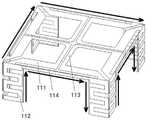
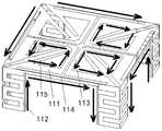
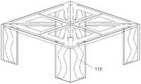
图13是本申请第三个实施例提供的双极化天线单元的结构示意图;13 is a schematic structural diagram of a dual-polarized antenna unit provided by a third embodiment of the present application;
图14是本申请第三个实施例提供的双极化天线单元的俯视图;14 is a top view of a dual-polarized antenna unit provided by a third embodiment of the present application;
图15是本申请第三个实施例提供的双极化天线单元的辐射体的结构示意图;15 is a schematic structural diagram of a radiator of a dual-polarized antenna unit provided by a third embodiment of the present application;
图16是本申请第三个实施例提供的S参数仿真结果图;Fig. 16 is an S-parameter simulation result diagram provided by the third embodiment of the present application;
图17是本申请第三个实施例提供的交叉极化比仿真结果图;17 is a cross-polarization ratio simulation result diagram provided by the third embodiment of the present application;
图18是本申请一个实施例提供的巴伦的结构示意图;18 is a schematic structural diagram of a balun provided by an embodiment of the present application;
图19是本申请一个实施例提供的巴伦等效电路的电路图。FIG. 19 is a circuit diagram of a balun equivalent circuit provided by an embodiment of the present application.
其中:1、辐射体;11、折合振子;111、振子臂;112、下垂弯折臂;113、共面带状线;114、公共臂;115、对称开路枝节;116、新振子臂;2、馈电结构;21、巴伦;22、馈电端口。Among them: 1, radiator; 11, folded oscillator; 111, oscillator arm; 112, pendulous bending arm; 113, coplanar strip line; 114, common arm; 115, symmetrical open branch; 116, new oscillator arm; 2 , Feeding structure; 21, Balun; 22, Feeding port.
具体实施方式Detailed ways
实施例:随着通讯设备越来越多,传输环境越来越复杂,不同频段、不同天线之间的耦合愈发严重,以双极化对称振子为主要辐射单元的基站天线要求的天线数量越来越多,而基站天线受天面资源的限制,基站天线要求向小型化、低耦合、一体化等方向发展,以减少布置空间,缓解天面资源紧张的压力。随着一体化基站天线的发展,需要将天线单元在限定的空间下与射频模块集成,小型化的基站天线的天线单元若体积能够减小,则对于同样的空间,可以实现多个阵列的布局,且能够进行有效的辐射。天线的小型化是指减小天线的尺寸,包括减小辐射单元口径以及降低天线剖面两个层面,隔离度是指天线之间相互干扰的程度,指一个天线发射信号,耦合到另一个天线上的信号与该发射天线信号的比值,隔离度通常与天线之间的距离有关,距离越大,隔离度越好。Example: With more and more communication devices, more and more complex transmission environments, and more serious coupling between different frequency bands and different antennas, the number of antennas required for base station antennas with dual-polarized symmetrical More and more, and the base station antenna is limited by the antenna resources, the base station antenna is required to develop in the direction of miniaturization, low coupling, integration, etc., in order to reduce the layout space and relieve the pressure of the tight antenna resources. With the development of integrated base station antennas, it is necessary to integrate the antenna unit with the radio frequency module in a limited space. If the volume of the antenna unit of the miniaturized base station antenna can be reduced, the layout of multiple arrays can be realized for the same space. , and can carry out effective radiation. The miniaturization of the antenna refers to reducing the size of the antenna, including reducing the diameter of the radiating element and reducing the antenna profile. Isolation refers to the degree of mutual interference between the antennas. The ratio of the signal to the transmitting antenna signal, the isolation is usually related to the distance between the antennas, the greater the distance, the better the isolation.
基站天线需要具有良好的定向辐射性,为了实现天线的定向辐射,将金属反射板放在天线的正下方,抑制天线的后向辐射并利用反射波束提高天线增益,为了补偿金属反射板造成的电磁波相位差并缓解金属反射板产生的镜像电流对天线辐射性能造成的不良影响,反射板与天线之间的距离一般采用谐振频点对应的四分之一波长,因此天线剖面较高,空间体积较大,为实现天线的小型化,天线的辐射单元尺寸必然缩小,从而导致谐振点往高频移动,为了使天线工作在频带范围内,同时缩小天线尺寸,本申请提供了一种双极化天线单元及基站天线,可以在双极化天线振子的性能保持不变的前提下缩减其尺寸。The base station antenna needs to have good directional radiation. In order to realize the directional radiation of the antenna, place the metal reflector directly under the antenna to suppress the backward radiation of the antenna and use the reflected beam to improve the antenna gain. In order to compensate for the electromagnetic waves caused by the metal reflector The phase difference can alleviate the adverse effect of the mirror current generated by the metal reflector on the antenna radiation performance. The distance between the reflector and the antenna generally adopts a quarter wavelength corresponding to the resonant frequency point, so the antenna profile is high and the space volume is relatively small. In order to realize the miniaturization of the antenna, the size of the radiating element of the antenna must be reduced, which will cause the resonance point to move to the high frequency. In order to make the antenna work within the frequency band and reduce the size of the antenna, the present application provides a dual-polarized antenna. The unit and base station antenna can be reduced in size on the premise that the performance of the dual-polarized antenna element remains unchanged.
如图1所示,本申请提供的双极化天线单元包括:辐射体1和馈电结构2;馈电结构2竖直支撑在辐射体1的下部。As shown in FIG. 1 , the dual-polarized antenna unit provided by the present application includes: a
结合参考图2和图3,辐射体1包括交叉极化的四个折合振子11,每个折合振子包括两个对称设置的振子臂111、下垂弯折臂112、共面带状线113和一个公共臂114;每个折合振子11中的两个振子臂111之间设有间隙;馈电结构2包括两个相互正交的巴伦21。其中,图3中的箭头表示辐射体1的电流分布。2 and 3 , the
公共臂114与振子臂111在同一平面内,公共臂114的两端分别与两个振子臂111的外侧两端连接,两个振子臂111的内侧两端垂直连接对应的共面带状线113;下垂弯折臂112连接在公共臂114的两端,下垂弯折臂112的平面与振子臂111和公共臂114的所在平面垂直;下垂弯折臂112为非闭合的弯折形状。The
每个折合振子11中的两个振子臂111之间设有间隙,两个共面带状线113之间设有间隙,每个共面带状线113连接对应位置的振子臂111的内侧端部,示例性的,两个共面带状线113之间保持平行。辐射体1由四个折合振子11组成,利用四个共面带状线113连接起来,利用场的叠加,可以形成±45°双极化。A gap is provided between the two
公共臂114的长度与两个振子臂111的外侧两端部之间的距离相等,示例性的,公共臂114与振子臂111保持平行。The length of the
下垂弯折臂112分别连接在公共臂114的两侧端部,对折合振子11的末端进行下垂延长设计,使得振子的电长度变长,电流路径延长,从而实现对称的极限尺寸。天线尺寸减小以后,谐振点向高频移动,由于天线小型化过程中平面结构的空间利用受到限制,在增加电流路径的思路下,将天线末端的电流引向下部空间,将会引入一个新的谐振点。The drooping and bending
下垂弯折臂112不仅将电流路径延长,同时引入了低频的谐振点,该谐振点的引入不仅展宽带宽,而且使得振子有了进一步继续缩小的空间,且对天线单元的隔离度并无恶化影响。通过对下垂弯折臂112的臂长及宽度进行配置,可以使双极化天线单元在要求的频段内匹配良好,同时其端口隔离度及交叉极化比达到设计要求。由图3中的电流分布可以看出,下垂弯折臂112的设计,不仅可以使得电流路径有效的延长,垂下来部分的电流,受边缘电流流向的影响,和边缘整体电流一样形成±45°双极化,对隔离影响很小。The drooping
在实际应用中,考虑到双极化天线单元的辐射性能以及组阵后单元间的耦合影响,下垂弯折臂112的长度不宜过长,需要根据振子本身进行调整。In practical applications, considering the radiation performance of the dual-polarized antenna unit and the coupling effect between the units after the array is formed, the length of the drooping
对于天线的性能,可以从匹配性能和交叉极化比来判定,天线一般用S参数的S11描述天线的匹配性能,S11表示一端口的反射系数,也就是一端口的输入回波损耗,回拨损耗是指入射功率与反射功率之比;基站天线一般设计为双极化,天线预定的极化方向定义为主极化,与其垂直的极化方向为交叉极化,其中交叉极化为无用分量,主极化与交叉极化的比值称为交叉极化比,交叉极化比越大,能量利用率越高。For the performance of the antenna, it can be judged from the matching performance and the cross-polarization ratio. The antenna generally usesS11 of the S parameter to describe the matching performance of the antenna, andS11 represents the reflection coefficient of a port, that is, the input return loss of a port, The callback loss refers to the ratio of the incident power to the reflected power; the base station antenna is generally designed to be dual-polarized, the predetermined polarization direction of the antenna is defined as the main polarization, and the polarization direction perpendicular to it is the cross-polarization, where the cross-polarization is For the useless component, the ratio of the main polarization to the cross polarization is called the cross polarization ratio. The larger the cross polarization ratio, the higher the energy utilization rate.
示例性的,对于图1至图3所示的双极化天线单元,图4示出了S参数仿真结果,图5示出了在频率2.2GHz下的交叉极化比仿真结果(方向图仿真结果),根据仿真结果,该双极化天线单元的交叉极化比在主方向上大于25 dB,在±60°范围内均大于10 dB,满足基站天线单元的设计要求。Exemplarily, for the dual-polarized antenna units shown in Figures 1 to 3, Figure 4 shows the S-parameter simulation results, and Figure 5 shows the cross-polarization ratio simulation results at a frequency of 2.2 GHz (pattern simulation results). Results), according to the simulation results, the cross-polarization ratio of the dual-polarized antenna unit is greater than 25 dB in the main direction and greater than 10 dB in the range of ±60°, which meets the design requirements of the base station antenna unit.
在实际仿真中,图1至图3所示的双极化天线单元,天线小型化之后的尺寸为0.21λ*0.21λ*0.21λ,实现了天线的小型化,同时天线的辐射性能良好,在工作频带1.7-2.2GHz内基本能够满足天线的设计要求,同时简化了双极化天线单元的辐射体的设计结构,有利于批量生产。In the actual simulation, the size of the dual-polarized antenna unit shown in Figure 1 to Figure 3 is 0.21λ*0.21λ*0.21λ after miniaturization, which realizes the miniaturization of the antenna, and the radiation performance of the antenna is good. The design requirements of the antenna can be basically met within the working frequency band of 1.7-2.2 GHz, and the design structure of the radiator of the dual-polarized antenna unit is simplified, which is beneficial to mass production.
可选的,结合参考图6至图8,折合振子11还包括对称开路枝节115;对称开路枝节115与振子臂111在同一平面;对称开路枝节115是由振子臂111的外侧端部向辐射体1的中心点延伸出开路的枝节结构,对称开路枝节115与辐射体1的中心点之间是断开的。其中,图8中的箭头表示辐射体1的电流分布。Optionally, referring to FIGS. 6 to 8 , the folded
通过增加对称开路枝节115,可以在辐射体1的平面上进一步延长电流路径,展宽带宽。By adding symmetrical open-
示例性的,对于图6至图8所示的双极化天线单元,图9示出了S参数仿真结果,图10示出了在频率2.2GHz下的交叉极化比仿真结果,根据仿真结果,该双极化天线单元的交叉极化比在主方向上大于25dB,在±60°范围内均大于10dB,具有良好的抗干扰能力,辐射性能良好,基本满足基站天线单元的设计要求。Exemplarily, for the dual-polarized antenna unit shown in FIGS. 6 to 8 , FIG. 9 shows the S-parameter simulation results, and FIG. 10 shows the cross-polarization ratio simulation results at a frequency of 2.2 GHz. According to the simulation results , the cross-polarization ratio of the dual-polarized antenna unit is greater than 25dB in the main direction and greater than 10dB in the range of ±60°. It has good anti-interference ability and good radiation performance, which basically meets the design requirements of base station antenna units.
在实际仿真中,图6至图8所示的双极化天线单元,天线小型化之后的尺寸为0.21λ*0.21λ*0.21λ,工作频带1.7-2.2GHz,驻波在1.5以下,隔离度在-30dB以下,基本能够满足天线的设计要求。In the actual simulation, for the dual-polarized antenna unit shown in Figure 6 to Figure 8, the size of the antenna after miniaturization is 0.21λ*0.21λ*0.21λ, the operating frequency band is 1.7-2.2GHz, the standing wave is below 1.5, and the isolation is Below -30dB, it can basically meet the design requirements of the antenna.
可选的,下垂弯折臂112的弯折形状至少包括弓字形、折线形、弧线形中的一种。将下垂弯折臂112设计成弯折形状,尤其是设计成弓字形,可以最大限度的利用向下弯折的空间,使得电流路径大大延长。示例性的,图1、图3、图6、图8中的下垂弯折臂112为弓字形弯折,图11中的下垂弯折臂112为折线形弯折,图12中的下垂弯折臂为弧线形弯折。Optionally, the bending shape of the drooping
可选的,下垂弯折臂112的弯折变化均匀,各个弯折部的长度相等,各个弯折区域的间距相等。均匀等间距的弯折使得下垂弯折臂112在有限的垂直空间内最大程度的延长有效电流路径,展宽带宽,保证天线的性能。Optionally, the bending variation of the drooping
可选的,四个折合振子11的振子臂111和公共臂114围成正方形,辐射体1的俯视平面为方形。Optionally, the
将方形辐射体1的振子的四个角落进行下弯折臂设计,引入了低频的谐振点,该谐振点的引入不仅可以展宽带宽,而且使得振子有了进一步继续缩小的空间,且对天线单元的其他性能无恶化影响,结构上制作简单,有利于大批量生产。The four corners of the vibrator of the
在一种可能的实现方式中,相邻两个折合振子11中的两个相邻的振子臂111之间设有间隙,相邻两个折合振子11中的两个相邻的下垂弯折臂112之间设有间隙。示例性的,图1至图3、图6至图8中的相邻两个折合振子11之间均设有间隙。In a possible implementation manner, a gap is provided between two
在另一种可能的实现方式中,结合参考图13至15,相邻两个折合振子11中的两个相邻的振子臂111相连,相邻两个折合振子11中的两个相邻的下垂弯折臂112相连;相连接的两个振子臂111、对应连接的共面带状线113以及位置对应的相连接的两个下垂弯折臂112组成新振子臂116,关于辐射体1的中心点呈中心对称的两个新振子臂116构成一个对称振子,示例性的,图14中虚线框内的两个新振子臂116构成一个对称振子,辐射体1包含两个对称振子。其中,图15中的箭头表示辐射体1的电流分布。In another possible implementation manner, referring to FIGS. 13 to 15 , two
对称振子是一种常用的天线形式,由两个对称的振子臂组成,两个振子臂的长度宽度相等,馈电点在中间的两个端点处。Symmetrical vibrator is a commonly used antenna form, which consists of two symmetrical vibrator arms, the length and width of the two vibrator arms are equal, and the feeding point is at the two endpoints in the middle.
图13至图15改变辐射体1的形状,将辐射体1的折合振子11转变成一对十字正交的方形环偶极子以及将其连接起来的边缘四条长截线(公共臂114),四个弯折角折下的弓字形下垂臂彼此之间无缝隙连接,具有良好的对称性。Figures 13 to 15 change the shape of the
示例性的,对于图13至图15所示的双极化天线单元,图16示出了S参数仿真结果,图17示出了在频率2GHz下的交叉极化比仿真结果,根据仿真结果,该双极化天线单元的交叉极化比在主方向上大于25 dB,在±60°范围内均大于10 dB,满足基站天线单元的设计要求。Exemplarily, for the dual-polarized antenna unit shown in FIG. 13 to FIG. 15 , FIG. 16 shows the S-parameter simulation results, and FIG. 17 shows the cross-polarization ratio simulation results at a frequency of 2 GHz. According to the simulation results, The cross-polarization ratio of the dual-polarized antenna unit is greater than 25 dB in the main direction and greater than 10 dB in the range of ±60°, which meets the design requirements of the base station antenna unit.
在实际仿真中,图13至图15所示的双极化天线单元,天线小型化之后的尺寸为0.21λ*0.21λ*0.21λ,实现了天线的小型化,且弯折臂的设计更加简单,同时天线的辐射性能良好,在工作频带1.7-2.2GHz内基本能够满足天线的设计要求。采用更加简单的结构实现了基本相同的辐射性能,便于加工操作,有利于批量生产。In the actual simulation, the size of the dual-polarized antenna unit shown in Figure 13 to Figure 15 is 0.21λ*0.21λ*0.21λ after miniaturization, which realizes the miniaturization of the antenna, and the design of the bending arm is simpler At the same time, the radiation performance of the antenna is good, and it can basically meet the design requirements of the antenna within the working frequency band of 1.7-2.2 GHz. By adopting a simpler structure, substantially the same radiation performance is achieved, which is convenient for processing operations and facilitates mass production.
对于图1至图3、图6至图8、图13至图15中三种双极化天线单元,根据仿真结果,三者的匹配性能和端口隔离度基本相同,满足基站天线单元工作的基本带宽,下垂弯折臂112上的电流流向相同,三者均满足基站天线单元的设计要求,并能够减小辐射体1的尺寸,实现天线单元的小型化。本申请提供的双极化天线单元小型化后,对于同样的空间,可以实现多个阵列的布局,且能进行有效的辐射,对于组阵后的去耦提供了更多的空间去实施去耦手段。For the three dual-polarized antenna units shown in Figure 1 to Figure 3, Figure 6 to Figure 8, and Figure 13 to Figure 15, according to the simulation results, the matching performance and port isolation of the three are basically the same, which satisfies the basic operation of the base station antenna unit. The bandwidth and the current flow on the sagging
在实际应用中,辐射体1可以直接通过金属加工成预定形状,也可以固定在介质板上,基于介质板加工出预定形状。In practical applications, the
可选的,辐射体1印刷在第一介质板上,馈电结构2印刷在第二介质板上,第二介质板垂直于第一介质板印刷有振子臂111的平面部分。Optionally, the
如图所示,第一介质板包括印刷振子臂111、公共臂114、共面带状线113的水平介质板以及印刷下垂弯折臂112的竖直介质板,馈电结构2印刷的第二介质板垂直于第一介质板印刷有振子臂111等结构的水平介质板。第二介质板不仅可以用于印刷馈电结构2,还能够起到支撑作用。As shown in the figure, the first dielectric plate includes the printed
示例性的,馈电结构2印刷在介电常数为3.55、介质板厚度为0.5mm的RogersRO4003介质板上,辐射体1印刷在介电常数为2.2、介质板厚度为1mm的Rogers 5880介质基板上。Exemplarily, the feeding
可选的,馈电结构2包括相互正交的两个第二介质板,每个第二介质板的一面印刷有Γ型巴伦,另一面印刷有短路贴片。Optionally, the feeding
对于馈电结构2的设计,为了平衡辐射体1上的电流,需要采用巴伦21平衡馈电。为了防止两个巴伦之间接触影响阻抗匹配,两个Γ型巴伦在竖直方向上设有高度差,每个Γ型巴伦分别与对应的馈电端口22连接,巴伦采用微带线的设计,经过阻抗变换,使天线达到匹配的状态。结合参考图18和图19,其示出了巴伦的模型及等效电路,示例性的,采用50Ω馈电,图19中的Zab是天线未加馈电结构的电阻,Zs为槽线的特性阻抗,Z1、Z2、Z3分别为图18中的三条微带线的特性阻抗,Z4为图18中的末端开路线特性阻抗,馈电点处的线路可以等效为一个理想的变压器,通过耦合给辐射体1进行馈电。For the design of the
示例性的,如图18所示,其示出了第二介质板印刷巴伦21的一面,第二介质板的另一面印刷整面的金属作为短路贴片,第二介质板的顶部具有凸起结构,第一介质板上设有与凸起结构对应的卡槽,凸起结构与卡槽配合固定连接第一介质板和第二介质板,凸起结构上的短路贴片部分从卡槽穿过与第一介质板上部的辐射体1接触,短路贴片用于实现辐射体1的接地。Exemplarily, as shown in FIG. 18 , it shows that one side of the
两个巴伦21被馈电端口22激励,将输入端口出的50Ω阻抗通过三节阻抗变换,在印刷巴伦21另一面的印刷有金属面之间的缝隙耦合到辐射体1上,耦合处可以等效为1:1的理想变压器,最后一节巴伦末端开路,辐射体1上激励起电流后,通过±45°极化产生两个谐振点,调节匹配和天线大小,使得阻抗和匹配都达到工作频带内的要求,且最大程度的实现天线单元的小型化。The two
综上所述,本申请提供的双极化天线单元,通过四个包括两个对称设置的振子臂、下垂弯折臂、共面带状线和一个公共臂的折合振子相互正交构成双极化天线单元,引入下垂弯折臂,将振子的电流路径延长,延长了天线的电流长度,避免振子尺寸直接缩小导致谐振点往高频移动的问题,解决了天线小型化过程中平面结构的空间利用受到限制的问题,将天线末端的电流引向下部空间,同时下垂弯折臂的设计引入了低频的谐振点,展宽了带宽,保持了天线振子的性能,达到了缩小双极化天线单元的尺寸,减少天线单元的布置空间,缓解天面资源紧张的压力,在双极化天线单元性能保持不变的前提下缩减其尺寸的效果。To sum up, the dual-polarized antenna unit provided by the present application constitutes a dipole through four folded vibrators including two symmetrically arranged vibrator arms, a drooping bending arm, a coplanar stripline and a common arm that are orthogonal to each other. The antenna unit is modified, and the drooping and bending arm is introduced to extend the current path of the vibrator, extending the current length of the antenna, avoiding the problem of the resonance point moving to high frequency due to the direct reduction of the vibrator size, and solving the space of the plane structure in the process of miniaturization of the antenna. Taking advantage of the restricted problem, the current at the end of the antenna is directed to the lower space. At the same time, the design of the drooping bending arm introduces a low-frequency resonance point, which widens the bandwidth, maintains the performance of the antenna oscillator, and achieves a reduction in the size of the dual-polarized antenna unit. size, reduce the layout space of the antenna unit, relieve the pressure of the tight antenna resources, and reduce the size of the dual-polarized antenna unit under the premise that the performance of the dual-polarized antenna unit remains unchanged.
另外,由于下垂臂过长会影响辐射方向图,通过将下垂弯折臂的弯折形状设置成弓字形、折线形、弧线形等形成,可以在有限的垂直空间中尽可能的延长电流路径,保证天线的性能。In addition, since the drooping arm is too long, the radiation pattern will be affected. By setting the bending shape of the drooping arm into a bow shape, a broken line shape, an arc shape, etc., the current path can be extended as much as possible in a limited vertical space. , to ensure the performance of the antenna.
另外,通过将下垂弯折臂均匀等间距的弯折,使得下垂弯折臂在有限的垂直空间内最大程度的延长有效电流路径,展宽带宽,保证天线的性能。In addition, by bending the drooping arm evenly and equidistantly, the drooping arm can extend the effective current path to the greatest extent in a limited vertical space, widen the bandwidth, and ensure the performance of the antenna.
另外,通过设置对称开路枝节,在平面上进一步延长电流路径,展宽带宽。In addition, by arranging symmetrical open-circuit branches, the current path is further extended on the plane and the bandwidth is widened.
另外,通过将相邻的折合振子连接起来,可以构成两组对称振子,结合下垂弯折臂的设计,同样可以延长电流路径,展宽带宽,保证天线的性能。In addition, by connecting adjacent folded oscillators, two sets of symmetrical oscillators can be formed. Combined with the design of the drooping bending arm, the current path can also be extended, the bandwidth can be widened, and the performance of the antenna can be guaranteed.
另外,通过在相邻的折合振子之间设置间隙,使得四个折合振子相互独立,结合下垂弯折臂的设计,可以延长电流路径,展宽带宽,保证天线的性能。In addition, by setting gaps between adjacent folded vibrators, the four folded vibrators are independent of each other, and combined with the design of the drooping bending arm, the current path can be extended, the bandwidth can be widened, and the performance of the antenna can be guaranteed.
另外,通过在第一介质板上印刷辐射体,在第二介质板上印刷馈电结构,不仅便于制作出辐射体的形状,而且起到支撑作用,第一介质板和第二介质板之间可以通过卡槽固定,以固定连接辐射体和馈电结构。In addition, by printing the radiator on the first dielectric board and printing the feed structure on the second dielectric board, it is not only convenient to make the shape of the radiator, but also plays a supporting role, between the first dielectric board and the second dielectric board It can be fixed by the card slot to fixedly connect the radiator and the feeding structure.
另外,通过对两个Γ型巴伦在竖直方向上设置高度差,可以防止两个巴伦之间接触导致影响阻抗匹配;通过在第二介质板的一面印刷巴伦,另一面全部印刷金属作为短路贴片,使得第一介质板与第二介质板通过卡槽固定时,短路贴片与第一介质板上表面印刷的辐射体接触,从而将辐射体接地。In addition, by setting the height difference of the two Γ-type baluns in the vertical direction, the contact between the two baluns can be prevented from affecting the impedance matching; by printing the baluns on one side of the second dielectric board, and printing all the metal on the other side As a short-circuit patch, when the first dielectric board and the second dielectric board are fixed through the slot, the short-circuit patch contacts the radiator printed on the surface of the first dielectric board, thereby grounding the radiator.
本申请还提供了一种基站天线,该基站天线包括如图1至图19所示的至少一个双极化天线单元以及设置在双极化天线单元底部的反射板,该反射板用于实现双极化天线单元的定向辐射。The present application also provides a base station antenna, the base station antenna includes at least one dual-polarized antenna unit as shown in FIG. 1 to FIG. 19 and a reflector disposed at the bottom of the dual-polarized antenna unit, the reflector is used to realize dual-polarization Directional radiation of polarized antenna elements.
在实际应用中,为了消除由于基站过于密集引起的负面干扰,通常选择具有良好的定向辐射特性的基站天线,为了实现天线的定向辐射,通常将金属反射板放置在天线单元的正下方,抑制天线的后向辐射并利用产生的反射波束提高天线的增益,为了补偿金属反射板造成的电磁波相位差并缓解金属反射板产生的镜像电流对天线辐射性能造成的不良影响,反射板与天线的辐射体之间的距离通常采用谐振频点对应的四分之一波长。In practical applications, in order to eliminate the negative interference caused by too dense base stations, base station antennas with good directional radiation characteristics are usually selected. In order to compensate the electromagnetic wave phase difference caused by the metal reflector and alleviate the adverse effect of the mirror current generated by the metal reflector on the antenna radiation performance, the reflector and the antenna radiator The distance between them is usually a quarter wavelength corresponding to the resonant frequency.
在实际应用中,基站天线还包括罩在双极化天线单元外部的天线罩。In practical applications, the base station antenna also includes a radome covering the outside of the dual-polarized antenna unit.
综上所述,本申请提供的基站天线,通过在反射板上布置多个双极化天线单元组成的阵列,可以实现双极化天线单元的定向辐射,由于每个双极化天线单元包括四个相互正交的折合振子,每个这个振子包括两个对称设置的振子臂、下垂弯折臂、共面带状线和一个公共臂,引入下垂弯折臂,将振子的电流路径延长,延长了天线的电流长度,避免振子尺寸直接缩小导致谐振点往高频移动的问题,解决了天线小型化过程中平面结构的空间利用受到限制的问题,将天线末端的电流引向下部空间,同时下垂弯折臂的设计引入了低频的谐振点,展宽了带宽,保持了天线振子的性能,达到了缩小双极化天线单元的尺寸,减少天线单元的布置空间,缓解天面资源紧张的压力,在双极化天线单元性能保持不变的前提下缩减其尺寸的效果,保证了各个天线单元之间的间距,避免间距过小造成天线单元之间的强烈互耦,有利于实现基站天线的小型化,低耦合,扩展带宽。To sum up, the base station antenna provided by this application can realize the directional radiation of the dual-polarized antenna units by arranging an array composed of multiple dual-polarized antenna units on the reflector. Since each dual-polarized antenna unit includes four There are two mutually orthogonal folded vibrators, each of which includes two symmetrically arranged vibrator arms, sagging arms, coplanar strip lines and a common arm. The current length of the antenna is reduced, avoiding the problem that the resonant point moves to the high frequency due to the direct reduction of the vibrator size, and solves the problem that the space utilization of the planar structure is limited in the process of antenna miniaturization. The design of the bent arm introduces a low-frequency resonance point, widens the bandwidth, maintains the performance of the antenna oscillator, reduces the size of the dual-polarized antenna unit, reduces the layout space of the antenna unit, and relieves the pressure of the sky resource shortage. The effect of reducing the size of the dual-polarized antenna unit under the premise that the performance of the dual-polarized antenna unit remains unchanged, ensures the spacing between the antenna units, and avoids strong mutual coupling between the antenna units due to too small spacing, which is conducive to realizing the miniaturization of the base station antenna. , low coupling, extended bandwidth.
另外,通过在双极化天线单元的外部设置天线罩,可以保护天线免受外部环境的影响。In addition, by arranging the radome outside the dual-polarized antenna unit, the antenna can be protected from the external environment.
术语“第一”、“第二”仅用于描述目的,而不能理解为指示或暗示相对重要性或隐含所指示的技术特征的数量。由此,限定的“第一”、“第二”的特征可以明示或隐含地包括一个或者更多个该特征。在本申请的描述中,除非另有说明,“多个”的含义是两个或者两个以上。The terms "first" and "second" are used for descriptive purposes only, and should not be understood as indicating or implying relative importance or implying the indicated number of technical features. Thus, a feature defined as "first", "second" may expressly or implicitly include one or more of that feature. In the description of this application, unless stated otherwise, "plurality" means two or more.
上述本申请实施例序号仅仅为了描述,不代表实施例的优劣。The above-mentioned serial numbers of the embodiments of the present application are only for description, and do not represent the advantages or disadvantages of the embodiments.
以上所述仅为本申请的较佳实施例,并不用以限制本申请,凡在本申请的精神和原则之内所作的任何修改、等同替换、改进等,均应包含在本申请的保护范围之内。The above descriptions are only preferred embodiments of the present application, and are not intended to limit the present application. Any modifications, equivalent replacements, improvements, etc. made within the spirit and principles of the present application shall be included in the protection scope of the present application. within.
Claims (9)
Translated fromChinesePriority Applications (1)
| Application Number | Priority Date | Filing Date | Title |
|---|---|---|---|
| CN202110267473.8ACN113131197B (en) | 2021-03-12 | 2021-03-12 | Dual-polarized antenna unit and base station antenna |
Applications Claiming Priority (1)
| Application Number | Priority Date | Filing Date | Title |
|---|---|---|---|
| CN202110267473.8ACN113131197B (en) | 2021-03-12 | 2021-03-12 | Dual-polarized antenna unit and base station antenna |
Publications (2)
| Publication Number | Publication Date |
|---|---|
| CN113131197A CN113131197A (en) | 2021-07-16 |
| CN113131197Btrue CN113131197B (en) | 2022-05-03 |
Family
ID=76772990
Family Applications (1)
| Application Number | Title | Priority Date | Filing Date |
|---|---|---|---|
| CN202110267473.8AActiveCN113131197B (en) | 2021-03-12 | 2021-03-12 | Dual-polarized antenna unit and base station antenna |
Country Status (1)
| Country | Link |
|---|---|
| CN (1) | CN113131197B (en) |
Families Citing this family (7)
| Publication number | Priority date | Publication date | Assignee | Title |
|---|---|---|---|---|
| CN113851847A (en)* | 2021-11-26 | 2021-12-28 | 华南理工大学 | Broadband stable high-gain antenna based on magnetoelectric dipole |
| CN114709603B (en)* | 2022-04-28 | 2024-04-12 | 摩比天线技术(深圳)有限公司 | Radiating element and antenna system |
| CN115411496B (en) | 2022-09-30 | 2025-09-16 | 苏州立讯技术有限公司 | Antenna element and antenna |
| CN116130930A (en) | 2022-10-09 | 2023-05-16 | 苏州立讯技术有限公司 | Vibrator arm and vibrator structure |
| CN116053808A (en)* | 2022-12-08 | 2023-05-02 | 西安电子科技大学 | A Dual Polarized Broadband Small Aperture Base Station Antenna |
| CN120657435A (en)* | 2024-03-15 | 2025-09-16 | 华为技术有限公司 | Antenna module and network equipment |
| CN120165223A (en)* | 2025-03-24 | 2025-06-17 | 中国科学院微小卫星创新研究院 | A dual circularly polarized antenna unit and a satellite-borne phased array antenna |
Citations (1)
| Publication number | Priority date | Publication date | Assignee | Title |
|---|---|---|---|---|
| CN106450691A (en)* | 2016-08-10 | 2017-02-22 | 京信通信技术(广州)有限公司 | Low-frequency radiation unit, antenna and multi-frequency common antenna |
Family Cites Families (11)
| Publication number | Priority date | Publication date | Assignee | Title |
|---|---|---|---|---|
| CN102013560B (en)* | 2010-09-25 | 2013-07-24 | 广东通宇通讯股份有限公司 | Broadband high-performance dual-polarized radiation unit and antenna |
| CN102694237B (en)* | 2012-05-21 | 2015-08-19 | 华为技术有限公司 | A kind of dual polarized antenna unit and antenna for base station |
| WO2016078475A1 (en)* | 2014-11-18 | 2016-05-26 | 李梓萌 | Miniaturized dipole base station antenna |
| CN104953241B (en)* | 2014-07-02 | 2018-04-27 | 广州司南天线设计研究所有限公司 | Minimize Bipolarization antenna for base station |
| EP3624262B1 (en)* | 2017-06-01 | 2024-02-28 | Huawei Technologies Co., Ltd. | Dual-polarized radiation unit, antenna, base station and communication system |
| CN109904585B (en)* | 2019-03-29 | 2024-11-15 | 摩比科技(深圳)有限公司 | Dual-polarization radiating unit and base station antenna |
| CN110401015B (en)* | 2019-07-01 | 2024-06-04 | 广东通宇通讯股份有限公司 | Ultra-wideband small-caliber dual-polarized crossing unit |
| CN210430080U (en)* | 2019-07-29 | 2020-04-28 | 华南理工大学 | Broadband dual-polarization filtering base station antenna unit, base station antenna array and communication equipment |
| CN110890617A (en)* | 2019-12-06 | 2020-03-17 | 广东盛路通信科技股份有限公司 | PCB oscillator bandwidth improving method, PCB oscillator and base station antenna radiation unit |
| CN210984959U (en)* | 2019-12-24 | 2020-07-10 | 比亚迪股份有限公司 | Feed balun for an antenna and antenna |
| CN111653869B (en)* | 2020-06-15 | 2022-09-13 | 广东工业大学 | Patch loaded broadband dual-polarized base station antenna |
- 2021
- 2021-03-12CNCN202110267473.8Apatent/CN113131197B/enactiveActive
Patent Citations (1)
| Publication number | Priority date | Publication date | Assignee | Title |
|---|---|---|---|---|
| CN106450691A (en)* | 2016-08-10 | 2017-02-22 | 京信通信技术(广州)有限公司 | Low-frequency radiation unit, antenna and multi-frequency common antenna |
Non-Patent Citations (2)
| Title |
|---|
| 《A Dual-Polarized Patch Antenna with High Isolation》;Luyu Zhao;《A Dual-Polarized Patch Antenna with High》;20200120;全文* |
| 《大规模基站天线去耦技术》;江嘉越;《2020中国信息通信大会论文集(CICC 2020)》;20201204;全文* |
Also Published As
| Publication number | Publication date |
|---|---|
| CN113131197A (en) | 2021-07-16 |
Similar Documents
| Publication | Publication Date | Title |
|---|---|---|
| CN113131197B (en) | Dual-polarized antenna unit and base station antenna | |
| US11489261B2 (en) | Dual-polarized wide-stopband filtering antenna and communications device | |
| CN109904613B (en) | Differential dual-frequency dual-polarized filtering antenna applied to 5G Sub 6GHz base station system | |
| CN111883910B (en) | A dual-polarized low-profile magnetoelectric dipole antenna and wireless communication device | |
| CN111987440B (en) | Compact self-isolation broadband antenna and mobile terminal | |
| CN112952368B (en) | Three-port mobile terminal antenna with self-decoupling characteristic | |
| CN114976665B (en) | Broadband dual-polarized dipole antenna loaded with stable frequency selective surface radiation | |
| WO2019062445A1 (en) | Multi-polarized radiation oscillator and antenna | |
| CN110034406A (en) | A kind of low section multi-beam slot antenna based on the double-deck super surface | |
| CN115882220B (en) | Wideband High Isolation Magnetoelectric Dipole Antenna and Communication Equipment for Full-duplex Applications | |
| CN111934089A (en) | Antenna device and mobile terminal | |
| CN108448234A (en) | Three-band MIMO terminal antenna based on composite left-handed transmission line structure | |
| CN115732925A (en) | A dual-polarized antenna array fed separately by millimeter-wave dual-frequency | |
| CN114374085A (en) | A dual-polarized hybrid antenna for 5G millimeter-wave dual-band applications | |
| CN111262005A (en) | Dual-polarized broadband magnetoelectric dipole antenna unit suitable for 5G base station and antenna array | |
| CN113497356A (en) | Dual-band dual-polarization filtering antenna | |
| CN111710973A (en) | Stacked differential broadband base station antenna | |
| CN112886234A (en) | Microwave millimeter wave coplanar common-caliber antenna based on embedded structure | |
| CN115911890B (en) | Dual-frequency dual-polarization magneto-electric dipole antenna array for millimeter wave mobile phone terminal | |
| CN118630472A (en) | A low-cost dual-frequency dual-polarization millimeter wave antenna | |
| CN207116688U (en) | Dual frequency high gain omnidirectional antenna | |
| CN112531355A (en) | +/-45-degree dual-polarized millimeter wave array antenna | |
| CN118448867B (en) | A broadband dual-polarized dielectric resonator filter antenna with differential feeding | |
| CN113497357A (en) | Broadband dual-polarization filtering antenna | |
| CN209282394U (en) | A kind of dual-band dual-polarized antenna based on substrate integration wave-guide |
Legal Events
| Date | Code | Title | Description |
|---|---|---|---|
| PB01 | Publication | ||
| PB01 | Publication | ||
| SE01 | Entry into force of request for substantive examination | ||
| SE01 | Entry into force of request for substantive examination | ||
| GR01 | Patent grant | ||
| GR01 | Patent grant |