CN113118966B - Bearing head for chemical mechanical polishing and using method thereof - Google Patents
Bearing head for chemical mechanical polishing and using method thereofDownload PDFInfo
- Publication number
- CN113118966B CN113118966BCN201911405848.1ACN201911405848ACN113118966BCN 113118966 BCN113118966 BCN 113118966BCN 201911405848 ACN201911405848 ACN 201911405848ACN 113118966 BCN113118966 BCN 113118966B
- Authority
- CN
- China
- Prior art keywords
- ring
- bearing
- head
- disc
- counterweight
- Prior art date
- Legal status (The legal status is an assumption and is not a legal conclusion. Google has not performed a legal analysis and makes no representation as to the accuracy of the status listed.)
- Active
Links
Images


Classifications
- B—PERFORMING OPERATIONS; TRANSPORTING
- B24—GRINDING; POLISHING
- B24B—MACHINES, DEVICES, OR PROCESSES FOR GRINDING OR POLISHING; DRESSING OR CONDITIONING OF ABRADING SURFACES; FEEDING OF GRINDING, POLISHING, OR LAPPING AGENTS
- B24B37/00—Lapping machines or devices; Accessories
- B24B37/04—Lapping machines or devices; Accessories designed for working plane surfaces
- B24B37/07—Lapping machines or devices; Accessories designed for working plane surfaces characterised by the movement of the work or lapping tool
- B24B37/10—Lapping machines or devices; Accessories designed for working plane surfaces characterised by the movement of the work or lapping tool for single side lapping
- B24B37/105—Lapping machines or devices; Accessories designed for working plane surfaces characterised by the movement of the work or lapping tool for single side lapping the workpieces or work carriers being actively moved by a drive, e.g. in a combined rotary and translatory movement
- B24B37/107—Lapping machines or devices; Accessories designed for working plane surfaces characterised by the movement of the work or lapping tool for single side lapping the workpieces or work carriers being actively moved by a drive, e.g. in a combined rotary and translatory movement in a rotary movement only, about an axis being stationary during lapping
- B—PERFORMING OPERATIONS; TRANSPORTING
- B24—GRINDING; POLISHING
- B24B—MACHINES, DEVICES, OR PROCESSES FOR GRINDING OR POLISHING; DRESSING OR CONDITIONING OF ABRADING SURFACES; FEEDING OF GRINDING, POLISHING, OR LAPPING AGENTS
- B24B37/00—Lapping machines or devices; Accessories
- B24B37/005—Control means for lapping machines or devices
- B—PERFORMING OPERATIONS; TRANSPORTING
- B24—GRINDING; POLISHING
- B24B—MACHINES, DEVICES, OR PROCESSES FOR GRINDING OR POLISHING; DRESSING OR CONDITIONING OF ABRADING SURFACES; FEEDING OF GRINDING, POLISHING, OR LAPPING AGENTS
- B24B37/00—Lapping machines or devices; Accessories
- B24B37/27—Work carriers
- B24B37/30—Work carriers for single side lapping of plane surfaces
- B—PERFORMING OPERATIONS; TRANSPORTING
- B24—GRINDING; POLISHING
- B24B—MACHINES, DEVICES, OR PROCESSES FOR GRINDING OR POLISHING; DRESSING OR CONDITIONING OF ABRADING SURFACES; FEEDING OF GRINDING, POLISHING, OR LAPPING AGENTS
- B24B49/00—Measuring or gauging equipment for controlling the feed movement of the grinding tool or work; Arrangements of indicating or measuring equipment, e.g. for indicating the start of the grinding operation
- B24B49/10—Measuring or gauging equipment for controlling the feed movement of the grinding tool or work; Arrangements of indicating or measuring equipment, e.g. for indicating the start of the grinding operation involving electrical means
- B24B49/105—Measuring or gauging equipment for controlling the feed movement of the grinding tool or work; Arrangements of indicating or measuring equipment, e.g. for indicating the start of the grinding operation involving electrical means using eddy currents
Landscapes
- Engineering & Computer Science (AREA)
- Mechanical Engineering (AREA)
- Finish Polishing, Edge Sharpening, And Grinding By Specific Grinding Devices (AREA)
- Mechanical Treatment Of Semiconductor (AREA)
Abstract
Description
Translated fromChinese技术领域technical field
本发明属于化学机械抛光技术领域,尤其涉及一种用于化学机械抛光的承载头及其使用方法。The invention belongs to the technical field of chemical mechanical polishing, and in particular relates to a bearing head for chemical mechanical polishing and a method for using the same.
背景技术Background technique
化学机械抛光是一种在芯片制造领域的主流基板抛光方法。这种抛光方法通常将基板吸合在承载头的下部,基板具有沉积层的一面抵接于旋转的抛光垫上,承载头在驱动部件的带动下与抛光垫同向旋转并给予基板向下的载荷;同时,抛光液供给于抛光垫的上表面并分布在基板与抛光垫之间,使得基板在化学和机械的综合作用下完成全局抛光。Chemical mechanical polishing is a mainstream substrate polishing method in the field of chip manufacturing. This polishing method usually attracts the substrate to the lower part of the carrier head, the side of the substrate with the deposited layer abuts on the rotating polishing pad, and the carrier head is driven by the driving component to rotate in the same direction as the polishing pad and give the substrate a downward load ; At the same time, the polishing liquid is supplied to the upper surface of the polishing pad and distributed between the substrate and the polishing pad, so that the substrate can complete the global polishing under the combined action of chemical and mechanical.
承载头是化学机械抛光装置的重要组成部分,其作业性能直接关系到基板的化学机械抛光效果。美国专利US20130065495A1公开了一种承载头,其包括承载盘及柔性膜,柔性膜可拆卸地设置在承载盘的下部;承载盘包括第一部分及第二部分,第一部分可移动地同心设置在第二部分的上部凹槽中使得第一部分和第二部分彼此之间可沿垂直于承载盘底面的方向运动。第二部分下部安装有柔性膜使得第二部分与柔性膜之间形成多个气腔以通过调节每个独立气腔的压力实现对基板压力轮廓的调节。现有技术中,外部空气经由第一部分上表面的气孔进入第一部分内部的通道并从第一部分侧壁上的气孔流出,然后经由气管输送至分别与独立气腔连通的第二部分的上表面的气孔。The carrier head is an important part of the chemical mechanical polishing device, and its performance is directly related to the chemical mechanical polishing effect of the substrate. US Patent US20130065495A1 discloses a carrier head, which includes a carrier plate and a flexible film, the flexible film is detachably arranged on the lower part of the carrier plate; the carrier plate includes a first part and a second part, the first part is movably arranged concentrically on the second part The upper groove of the part allows the first part and the second part to move relative to each other in a direction perpendicular to the bottom surface of the carrier tray. A flexible membrane is installed at the lower part of the second part, so that a plurality of air cavities are formed between the second part and the flexible membrane, so as to adjust the pressure profile of the substrate by adjusting the pressure of each independent air cavity. In the prior art, the external air enters the channel inside the first part through the air hole on the upper surface of the first part and flows out from the air hole on the side wall of the first part, and then is transported through the air pipe to the upper surface of the second part which is respectively communicated with the independent air cavity. stomata.
承载头的下部设置有保持环,其在基板的化学机械抛光中发挥重要作用。一方面,其可以防止抛光过程的基板从承载头的底部滑脱或飞出;另一方面,保持环的底部设置有沟槽,其可以为更新基板与抛光垫之间的抛光液提供流体通道;再者,保持环抵压于抛光垫参与基板边缘压力的调整,有利于实现基板的全局平坦化并改善平坦化的一致性。The lower part of the carrier head is provided with a retaining ring, which plays an important role in the chemical mechanical polishing of the substrate. On the one hand, it can prevent the substrate in the polishing process from slipping off or flying out from the bottom of the carrier head; on the other hand, the bottom of the retaining ring is provided with a groove, which can provide a fluid channel for the polishing liquid between the renewal substrate and the polishing pad; Furthermore, the holding ring is pressed against the polishing pad to participate in the adjustment of the edge pressure of the substrate, which is beneficial to realize the global planarization of the substrate and improve the uniformity of the planarization.
在化学机械抛光过程中,为了实时调节材料去除速率,需要在线测量待去除材料层的厚度,当待去除材料为金属时,电涡流膜厚测量方法比较适用。现有的电涡流膜厚测量装置通过信号发生器产生交变电磁场信号,使基板的金属膜中形成电涡流,通过传感器检测由所述金属膜中的电涡流引起的电感变化信号,并由此确定金属膜的厚度。In the chemical mechanical polishing process, in order to adjust the material removal rate in real time, it is necessary to measure the thickness of the material layer to be removed online. When the material to be removed is metal, the eddy current film thickness measurement method is more suitable. The existing eddy current film thickness measurement device generates an alternating electromagnetic field signal through a signal generator, so that an eddy current is formed in the metal film of the substrate, and the sensor detects the inductance change signal caused by the eddy current in the metal film, and thereby Determine the thickness of the metal film.
化学机械抛光终点检测的检测精度要求随着特征结构尺寸的不断缩小而提高,由于传统的化学机械抛光承载头的保持环等部件内包含金属部件或金属材料,在电涡流膜厚测量中所述金属部件内也会产生电涡流,从而会对传感器获取的信号造成干扰,影响终点检测的精度。因此,希望能够在测量基板的金属结构特征厚度以判断化学机械抛光终点时保证承载头的金属结构尽量少地干扰所述测量信号。The detection accuracy of chemical mechanical polishing end point detection is required to increase with the continuous reduction of the feature size. Since the traditional chemical mechanical polishing carrier head contains metal parts or metal materials such as the retaining ring, it is described in the eddy current film thickness measurement. Eddy currents can also be generated in metal parts, which can interfere with the signal acquired by the sensor and affect the accuracy of endpoint detection. Therefore, it is desirable to ensure that the metal structure of the carrier head interferes with the measurement signal as little as possible when measuring the thickness of the metal structure feature of the substrate to determine the end point of chemical mechanical polishing.
为了减轻电磁干扰,可采用塑料制造用于抛光金属层的承载头的主体。这又带来两个方面的影响:承载头的重量减轻,抛光时的下压力减小,抛光结果受到影响;承载头的转动惯量减小,电机惯量与负载惯量不匹配,稳定性变差。从而,对抛光金属和非金属的两种承载头需要设计两套不同的软硬件。To mitigate electromagnetic interference, the body of the carrier head for polishing the metal layer can be made of plastic. This has two effects: the weight of the carrier head is reduced, the downforce during polishing is reduced, and the polishing results are affected; the rotational inertia of the carrier head is reduced, the motor inertia does not match the load inertia, and the stability is deteriorated. Therefore, two different sets of software and hardware need to be designed for the two bearing heads of polished metal and non-metal.
发明内容SUMMARY OF THE INVENTION
本发明提供了一种化学机械抛光承载头的配重方法,旨在一定程度上解决上述技术问题之一,其技术方案如下:一种用于化学机械抛光的承载头,包括:连轴盘、平衡架、承载盘、环状弹性膜、第一夹环和第二夹环;所述第一夹环将所述环状弹性膜的外缘夹紧结合至所述承载盘并且所述第二夹环将所述环状弹性膜的内缘夹紧结合至所述连轴盘;所述平衡架的中轴部滑动密封地设置于所述连轴盘的中心通孔内并可以通过其底盘部及翼缘部带动承载盘相对于连轴盘上下移动;所述承载盘由非导电材料制成并且其上方固定有配重。The invention provides a counterweight method for a chemical mechanical polishing bearing head, aiming at solving one of the above-mentioned technical problems to a certain extent. A gimbal, a carrier plate, an annular elastic film, a first clamp ring, and a second clamp ring; the first clamp ring clamps the outer edge of the annular elastic film to the carrier plate and the second clamp ring The clamping ring clamps the inner edge of the annular elastic film to the connecting disc; the central shaft portion of the gimbal is slidably and sealingly arranged in the central through hole of the connecting disc and can pass through its chassis The bearing plate and the flange portion drive the bearing plate to move up and down relative to the connecting plate; the bearing plate is made of non-conductive material and a counterweight is fixed above it.
进一步的,所述第一夹环由金属材料制成。Further, the first clamping ring is made of metal material.
进一步的,所述承载盘的上表面可拆卸地连接有第一配重环,所述第一配重环由金属材料制成。Further, a first counterweight ring is detachably connected to the upper surface of the carrier plate, and the first counterweight ring is made of a metal material.
进一步的,所述连轴盘上固定有配重。Further, a counterweight is fixed on the coupling disc.
进一步的,所述第二夹环由金属材料制成。Further, the second clamping ring is made of metal material.
进一步的,所述连轴盘的上表面可拆卸地连接有第二配重环,所述第二配重环由金属材料制成。Further, a second counterweight ring is detachably connected to the upper surface of the coupling disc, and the second counterweight ring is made of a metal material.
根据本发明的另一方面,本发明还提出了一种用于化学机械抛光的承载头的使用方法,包括如下步骤:S1.确定非导电材料制造的承载盘的重量;S2.根据承载盘的重量确定需要增加的配重值;S3.根据需要增加的配重值确定第一夹环的材质和体积;S4.根据承载头的转动惯量确定第一夹环的外形。According to another aspect of the present invention, the present invention also proposes a method for using a carrier head for chemical mechanical polishing, comprising the following steps: S1. Determine the weight of the carrier plate made of non-conductive material; S2. According to the weight of the carrier plate Determine the counterweight value to be added by weight; S3. Determine the material and volume of the first clamping ring according to the counterweight value to be added; S4. Determine the shape of the first clamping ring according to the moment of inertia of the bearing head.
作为改进,根据本发明的承载头使用方法,包括如下步骤:S1.确定非导电材料制造的承载盘的重量;S2.根据承载盘的重量确定需要增加的配重值;S3.根据需要增加的配重值确定第一配重环的材质和体积;S4.根据承载头的转动惯量确定第一配重环的外形。As an improvement, the method for using the carrying head according to the present invention includes the following steps: S1. Determine the weight of the carrying plate made of non-conductive material; S2. Determine the counterweight value to be added according to the weight of the carrying plate; S3. Increase according to the need The weight value determines the material and volume of the first weight ring; S4. Determine the shape of the first weight ring according to the moment of inertia of the bearing head.
进一步的,所述使用方法还包括如下步骤:S5.根据承载头的转动惯量确定第二夹环的材质、体积和外形。Further, the using method further includes the following steps: S5. Determine the material, volume and shape of the second clamping ring according to the moment of inertia of the bearing head.
本发明实施例与现有技术相比存在的有益效果包括:减小了在电涡流金属膜厚测量过程中承载头主体对检测信号的干扰、提高了检测精度;提高了承载头的通用性,无需设计两套驱动系统,减小了成本。Compared with the prior art, the beneficial effects of the embodiments of the present invention include: reducing the interference of the main body of the bearing head to the detection signal during the eddy current metal film thickness measurement process, improving the detection accuracy; improving the versatility of the bearing head, There is no need to design two sets of drive systems, which reduces the cost.
附图说明Description of drawings
通过结合以下附图所作的详细描述,本发明的优点将变得更清楚和更容易理解,但这些附图只是示意性的,并不限制本发明的保护范围,其中:The advantages of the present invention will become clearer and easier to understand through the detailed description in conjunction with the following drawings, but these drawings are only schematic and do not limit the protection scope of the present invention, wherein:
图1是抛光单元的基本结构构造的立体示意图;Fig. 1 is the three-dimensional schematic diagram of the basic structure of polishing unit;
图2是现有技术中化学机械抛光承载头的剖视图;2 is a cross-sectional view of a chemical mechanical polishing bearing head in the prior art;
图3是用于去除金属材料层的化学机械抛光承载头的剖面图;3 is a cross-sectional view of a chemical mechanical polishing carrier head for removing a metal material layer;
图4是图3所示的承载头的局部放大图;Fig. 4 is a partial enlarged view of the carrier head shown in Fig. 3;
图5示出了第一配重环与第一夹环同轴可拆卸地连接于承载盘之上的承载头;Fig. 5 shows the carrier head in which the first counterweight ring and the first clamping ring are coaxially and detachably connected to the carrier plate;
图6示出了第二配重环与第二夹环同轴可拆卸地连接于连轴盘之上的承载头。FIG. 6 shows the bearing head in which the second weight ring and the second clamping ring are coaxially and detachably connected to the coupling disc.
具体实施方式Detailed ways
下面结合具体实施例及其附图,对本发明所述技术方案进行详细说明。在此记载的实施例为本发明的特定的具体实施方式,用于说明本发明的构思;这些说明均是解释性和示例性的,不应理解为对本发明实施方式及本发明保护范围的限制。除在此记载的实施例外,本领域技术人员还能够基于本申请权利要求书及其说明书所公开的内容采用显而易见的其它技术方案,这些技术方案包括采用对在此记载的实施例的做出任何显而易见的替换和修改的技术方案。为了说明本发明所述的技术方案,下面通过具体实施例来进行说明。The technical solutions of the present invention will be described in detail below with reference to specific embodiments and accompanying drawings. The embodiments described herein are specific embodiments of the present invention, used to illustrate the concept of the present invention; these descriptions are all explanatory and exemplary, and should not be construed as limiting the embodiments of the present invention and the protection scope of the present invention . In addition to the embodiments described herein, those skilled in the art can also adopt other obvious technical solutions based on the content disclosed in the claims of the present application and the description thereof, and these technical solutions include adopting any modifications made to the embodiments described herein. Obvious alternative and modified technical solutions. In order to illustrate the technical solutions of the present invention, the following specific embodiments are used for description.
图1是抛光单元的基本结构构造的立体示意图,抛光单元包括抛光盘10、抛光垫20、基板承载装置30、修整装置40以及抛光液供应装置50;抛光垫20设置于抛光盘10上表面并与其一起同步绕轴旋转;可水平移动的基板承载装置30设置于抛光垫20上方,其所耦接的承载头的下表面吸持有待抛光的基板W;修整装置40包括修整臂41及修整头42,修整臂41带动旋转的修整头42摆动以修整抛光垫20表面使其达到适于抛光的优化状态;抛光液供应装置50将抛光液散布于抛光垫20的上表面;进行化学机械抛光作业时,基板承载装置30将基板W的待抛光面抵压于抛光垫20的上表面,抛光液分布于抛光垫20与基板W之间,在化学和机械的作用下完成基板材料的去除。基板承载装置30包括承载头31及上部气动组件32(UPA,Upper Pneumatic Assembly),承载头31通过未示出的连接组件耦接至上部气动组件32。当基板上待去除的材料层为金属层时,可采用电涡流方式实时检测金属层厚度和抛光终点,嵌入设置在抛光盘10与抛光垫20之间的电涡流检测装置11向基板W方向发射电磁波以测量基板表面金属层的厚度以捕获抛光终点,但承载头31内部的金属部件会产生电涡流和电磁波反射进而对电涡流检测装置11的信号测量精度造成影响,特别是承载头中位置较低的、靠近基板W的金属部件对抛光终点的检测会造成显著影响。1 is a three-dimensional schematic diagram of the basic structure of a polishing unit. The polishing unit includes a
图2是现有技术中化学机械抛光承载头的剖视图,承载头31包括连轴盘311、平衡架312、承载盘313、环状弹性膜314、第一夹环315和第二夹环316等。其中,连轴盘311通过未示出的连接组件耦接于外部驱动组件以带动整个承载头31移动和/或旋转;第一夹环315将环状弹性膜314的外缘夹紧结合至承载盘313并且第二夹环316将环状弹性膜314的内缘夹紧结合至连轴盘311使得承载盘313可随连轴盘311一体旋转;具有中轴部、底盘部、周壁部和翼缘部的平衡架312与连轴盘311同轴设置,其中轴部可滑动地插入至连轴盘311的中心轴孔中并可在其中沿竖直方向移动,其翼缘部借助垫圈、第三夹环以及未示出的螺栓结合至承载盘313的中心阶梯孔,使得承载盘313与平衡架312一起旋转和/或沿竖直方向移动;可以通过连轴盘311中的沿竖直方向与平衡架312的中轴部平行延伸的通孔来调节可调压腔室的压力,以调节承载盘313沿竖直方向相对于连轴盘311的位移;承载头31中,承载盘313以及与承载盘313固定连接的部分可以合称为浮动部分,连轴盘311以及与连轴盘311固定连接的部分可以合称为固定部分,浮动部分在随固定部分一体旋转和/或平动的同时可以受控沿竖直方向相对固定部分进行上下移动。2 is a cross-sectional view of a chemical mechanical polishing carrier head in the prior art. The
图3是用于去除金属材料层的化学机械抛光承载头的剖面图,由于现有技术中承载头31的承载盘313通常采用诸如铝合金的金属材料制成,在电涡流测量中金属材质的承载盘313内也会产生电涡流,从而会对电涡流检测装置11获取的信号造成干扰,影响终点检测的精度。为此,可将承载盘313改为采用诸如PPS、PEEK、聚碳酸酯、聚氨酯、聚亚氨酯、或PET的硬质工程塑料制成,利用塑料的绝缘性能避免产生电涡流,提高检测精度。由于塑料的密度较小,若将现有承载头31中的承载盘313直接由金属材质替换为非金属材质会使承载头31的总重量减小,将进行上述替换后的承载头31直接应用于原抛光单元,会导致下压力减小,若继续采用原有的抛光参数,得到的抛光结果将会不同;同时,由于改进后的承载头31的转动惯量减小,导致原驱动组件的电机惯量与负载惯量不匹配,系统稳定性变差。因此,若要将承载盘313直接由金属材质替换为非金属材质,抛光单元的软硬件需要进行适应性修改,即原有的金属承载盘的承载头和改进后的塑料承载盘的承载头在使用中需要对应两套不同的软硬件。3 is a cross-sectional view of a chemical mechanical polishing carrier head for removing a metal material layer. Since the
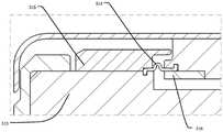
为了提高承载头的通用性、降低使用成本,可以对承载头进行配重。图4是图3的局部放大图,当采用塑料制作承载盘313时,承载盘313上方固定有配重。例如,可对现有承载头31的第一夹环315进行增重,将其材质由工程塑料改为诸如不锈钢或钨合金的密度较大的材料,同时,还可以增大第一夹环315的外径、厚度等尺寸,使得改进后的承载头31中第一夹环315增加的重量与承载盘313减少的重量相同,从而使得承载头31浮动部分的总重量不变,进而确保采用相同抛光参数时,承载头31的下压力不变。由于第一夹环315位于承载盘313上方,距离电涡流检测装置11较远,其内部产生的电涡流强度低,对电涡流厚度测量的干扰小,可以忽略。In order to improve the versatility of the carrying head and reduce the use cost, the carrying head can be counterweighted. FIG. 4 is a partial enlarged view of FIG. 3 . When the
另一方面,在设计第一夹环315的外形时还需考虑改进后的承载头31的转动惯量,应尽量确保其转动惯量与现有的承载头的转动惯量接近,按照上述方法对承载头31进行配重的步骤如下:确定采用塑料等非导电材料制造的承载盘313的重量;根据承载盘313的重量确定需要增加的配重值;根据需要增加的配重值确定第一夹环315的材质和体积;根据承载头31的转动惯量确定第一夹环315的外形。On the other hand, when designing the shape of the
类似地,可以在承载盘313的上表面设置单独的第一配重环317,如图5所示,第一配重环317与第一夹环315同轴设置,并且可拆卸地连接于承载盘313之上。第一配重环317可以采用诸如不锈钢或钨合金的密度较大的材料,可以根据承载盘313改用塑料材质后所减少的重量设置第一配重环317的尺寸,使得第一配重环317的重量与承载盘313减少的重量相同。Similarly, a single
另一方面,在设计第一配重环317的外形时还需考虑改进后的承载头31的转动惯量,应尽量确保其转动惯量与现有的承载头的转动惯量接近,按照上述方法对承载头31进行配重的步骤如下:确定采用塑料等非导电材料制造的承载盘313的重量;根据承载盘313的重量确定需要增加的配重值;根据需要增加的配重值确定第一配重环317的材质和体积;根据承载头31的转动惯量确定第一配重环317的外形。On the other hand, when designing the shape of the
上述配重设计可以确保承载头31的浮动部分重量不变,进而使得相同抛光参数下承载头对基板的下压力不变。然而,由于承载盘313的径向重量分布更靠近其外周,塑料材质的承载盘313进行上述配重设计之后,转动惯量可能仍然会减小,导致承载头31的总体转动惯量减小。为此,可以进一步对承载头31的固定部分进行配重。例如,可对现有承载头31的第二夹环316进行增重,将其材质由工程塑料改为诸如不锈钢或钨合金的密度较大的材料,同时,还可以增大第二夹环316的外径、厚度等尺寸,使得改进后的承载头31中固定部分增加的转动惯量与浮动部分减少的转动惯量相同,从而使得承载头31的整体转动惯量不变,进而确保采用相同驱动组件时,系统稳定性不变。由于第二夹环316位于承载盘313上方,距离电涡流检测装置11较远,其内部产生的电涡流强度低,对电涡流厚度测量的干扰小,可以忽略。按照上述方法对承载头31进行配重的步骤如下:确定采用塑料等非导电材料制造的承载盘313的重量;根据承载盘313的重量确定需要增加的配重值;根据需要增加的配重值确定第一夹环315和/或第一配重环317的材质和体积;根据承载头31的转动惯量确定第一夹环315和/或第一配重环317的外形;根据承载头31的转动惯量确定第二夹环316的材质、体积和外形。The above-mentioned counterweight design can ensure that the weight of the floating part of the
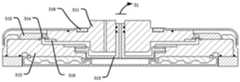
类似地,可以在连轴盘311的上表面设置单独的第二配重环318,如图6所示,第二配重环318与第二夹环316同轴设置,并且可拆卸地连接于连轴盘311之上。第二配重环318可以采用诸如不锈钢或钨合金的密度较大的材料,可以根据承载盘313改用塑料材质后所减少的转动惯量设置第二配重环318的尺寸,使得改进后的承载头31整体转动惯量不变。按照上述方法对承载头31进行配重的步骤如下:确定采用塑料等非导电材料制造的承载盘313的重量;根据承载盘313的重量确定需要增加的配重值;根据需要增加的配重值确定第一夹环315和/或第一配重环317的材质和体积;根据承载头31的转动惯量确定第一夹环315和/或第一配重环317的外形;根据承载头31的转动惯量确定第二配重环318的材质、体积和外形。Similarly, a separate
在上述实施例中,对各个实施例的描述都各有侧重,各实施例可以任意组合,组合后形成的新的实施例也在本申请的保护范围之内。某个实施例中没有详述或记载的部分,可以参见其它实施例的相关描述。In the above-mentioned embodiments, the description of each embodiment has its own emphasis, and each embodiment can be combined arbitrarily, and a new embodiment formed after the combination is also within the protection scope of the present application. For parts that are not described or described in detail in a certain embodiment, reference may be made to related descriptions of other embodiments.
以上所述实施例仅用以说明本发明的技术方案,而非对其限制;尽管参照前述实施例对本发明进行了详细的说明,本领域的普通技术人员应当理解:其依然可以对前述各实施例所记载的技术方案进行修改,或者对其中部分技术特征进行等同替换;而这些修改或者替换,并不使相应技术方案的本质脱离本发明各实施例技术方案的精神和范围,均应包含在本发明的保护范围之内。The above-mentioned embodiments are only used to illustrate the technical solutions of the present invention, but not to limit them; although the present invention has been described in detail with reference to the foregoing embodiments, those of ordinary skill in the art should understand that: it is still possible to implement the foregoing implementations. The technical solutions described in the examples are modified, or some technical features thereof are equivalently replaced; and these modifications or replacements do not make the essence of the corresponding technical solutions deviate from the spirit and scope of the technical solutions of the embodiments of the present invention, and should be included in the within the protection scope of the present invention.
Claims (8)
Priority Applications (1)
| Application Number | Priority Date | Filing Date | Title |
|---|---|---|---|
| CN201911405848.1ACN113118966B (en) | 2019-12-31 | 2019-12-31 | Bearing head for chemical mechanical polishing and using method thereof |
Applications Claiming Priority (1)
| Application Number | Priority Date | Filing Date | Title |
|---|---|---|---|
| CN201911405848.1ACN113118966B (en) | 2019-12-31 | 2019-12-31 | Bearing head for chemical mechanical polishing and using method thereof |
Publications (2)
| Publication Number | Publication Date |
|---|---|
| CN113118966A CN113118966A (en) | 2021-07-16 |
| CN113118966Btrue CN113118966B (en) | 2022-08-16 |
Family
ID=76768753
Family Applications (1)
| Application Number | Title | Priority Date | Filing Date |
|---|---|---|---|
| CN201911405848.1AActiveCN113118966B (en) | 2019-12-31 | 2019-12-31 | Bearing head for chemical mechanical polishing and using method thereof |
Country Status (1)
| Country | Link |
|---|---|
| CN (1) | CN113118966B (en) |
Families Citing this family (1)
| Publication number | Priority date | Publication date | Assignee | Title |
|---|---|---|---|---|
| CN115502882B (en)* | 2022-10-27 | 2025-06-17 | 华海清科股份有限公司 | A carrier head for chemical mechanical polishing and chemical mechanical polishing equipment |
Citations (14)
| Publication number | Priority date | Publication date | Assignee | Title |
|---|---|---|---|---|
| DE4304429A1 (en)* | 1992-02-14 | 1993-09-16 | Lsi Logic Corp | |
| JP2003175455A (en)* | 2001-12-12 | 2003-06-24 | Ebara Corp | Substrate holding device and polishing apparatus |
| WO2003098673A1 (en)* | 2002-05-21 | 2003-11-27 | Sony Corporation | Polishing method and polishing system, and method for fabricating semiconductor device |
| CN101023511A (en)* | 2004-09-30 | 2007-08-22 | 株式会社瑞萨科技 | Method for manufacturing semiconductor device |
| JP2008066761A (en)* | 2007-11-29 | 2008-03-21 | Ebara Corp | Substrate holding device |
| CN101903995A (en)* | 2007-12-20 | 2010-12-01 | 欧司朗光电半导体有限公司 | Method for producing semiconductor chips and corresponding semiconductor chip |
| CN102049733A (en)* | 2010-07-26 | 2011-05-11 | 清华大学 | Eddy current metal film thickness end point detection device |
| CN103624674A (en)* | 2012-08-27 | 2014-03-12 | 深圳富泰宏精密工业有限公司 | Grinding miller lifting mechanism and grinding miller using the lifting mechanism |
| CN103889656A (en)* | 2011-09-12 | 2014-06-25 | 应用材料公司 | Carrier head with composite plastic portions |
| CN104854680A (en)* | 2012-11-30 | 2015-08-19 | 应用材料公司 | Three-zone carrier head and flexible membrane |
| CN109366344A (en)* | 2017-04-12 | 2019-02-22 | 株式会社荏原制作所 | Elastic membrane, base plate keeping device and grinding device |
| CN109689295A (en)* | 2016-09-15 | 2019-04-26 | 应用材料公司 | Chemically-mechanicapolish polish intelligent ring |
| CN209036165U (en)* | 2018-11-07 | 2019-06-28 | 上海欧柏森环境工程管理有限公司 | A kind of adaptive ground burnishing device |
| CN110524412A (en)* | 2019-09-30 | 2019-12-03 | 清华大学 | Chemical mechanical polishing retaining ring and chemical mechanical polishing bearing head |
Family Cites Families (2)
| Publication number | Priority date | Publication date | Assignee | Title |
|---|---|---|---|---|
| JP4102081B2 (en)* | 2002-02-28 | 2008-06-18 | 株式会社荏原製作所 | Polishing apparatus and foreign matter detection method for polished surface |
| KR101036605B1 (en)* | 2008-06-30 | 2011-05-24 | 세메스 주식회사 | Substrate support unit and sheet type substrate polishing apparatus using the same |
- 2019
- 2019-12-31CNCN201911405848.1Apatent/CN113118966B/enactiveActive
Patent Citations (14)
| Publication number | Priority date | Publication date | Assignee | Title |
|---|---|---|---|---|
| DE4304429A1 (en)* | 1992-02-14 | 1993-09-16 | Lsi Logic Corp | |
| JP2003175455A (en)* | 2001-12-12 | 2003-06-24 | Ebara Corp | Substrate holding device and polishing apparatus |
| WO2003098673A1 (en)* | 2002-05-21 | 2003-11-27 | Sony Corporation | Polishing method and polishing system, and method for fabricating semiconductor device |
| CN101023511A (en)* | 2004-09-30 | 2007-08-22 | 株式会社瑞萨科技 | Method for manufacturing semiconductor device |
| JP2008066761A (en)* | 2007-11-29 | 2008-03-21 | Ebara Corp | Substrate holding device |
| CN101903995A (en)* | 2007-12-20 | 2010-12-01 | 欧司朗光电半导体有限公司 | Method for producing semiconductor chips and corresponding semiconductor chip |
| CN102049733A (en)* | 2010-07-26 | 2011-05-11 | 清华大学 | Eddy current metal film thickness end point detection device |
| CN103889656A (en)* | 2011-09-12 | 2014-06-25 | 应用材料公司 | Carrier head with composite plastic portions |
| CN103624674A (en)* | 2012-08-27 | 2014-03-12 | 深圳富泰宏精密工业有限公司 | Grinding miller lifting mechanism and grinding miller using the lifting mechanism |
| CN104854680A (en)* | 2012-11-30 | 2015-08-19 | 应用材料公司 | Three-zone carrier head and flexible membrane |
| CN109689295A (en)* | 2016-09-15 | 2019-04-26 | 应用材料公司 | Chemically-mechanicapolish polish intelligent ring |
| CN109366344A (en)* | 2017-04-12 | 2019-02-22 | 株式会社荏原制作所 | Elastic membrane, base plate keeping device and grinding device |
| CN209036165U (en)* | 2018-11-07 | 2019-06-28 | 上海欧柏森环境工程管理有限公司 | A kind of adaptive ground burnishing device |
| CN110524412A (en)* | 2019-09-30 | 2019-12-03 | 清华大学 | Chemical mechanical polishing retaining ring and chemical mechanical polishing bearing head |
Non-Patent Citations (1)
| Title |
|---|
| 化学机械抛光压力控制技术研究;刘 涛 等;《电子工业专用设备》;20100920;第11页* |
Also Published As
| Publication number | Publication date |
|---|---|
| CN113118966A (en) | 2021-07-16 |
Similar Documents
| Publication | Publication Date | Title |
|---|---|---|
| CN110524412B (en) | Chemical mechanical polishing retaining ring and chemical mechanical polishing bearing head | |
| JP5511600B2 (en) | Polishing equipment | |
| CN102765012B (en) | Flexible controllable air bag polishing tool based on electrorheological fluid | |
| JP2023075085A (en) | Polishing device using monitoring neural network | |
| CN103659575A (en) | Grinding method and grinding device | |
| US20120270477A1 (en) | Measurement of pad thickness and control of conditioning | |
| CN103506940B (en) | Chemical mechanical polishing wafer carrier | |
| CN113118966B (en) | Bearing head for chemical mechanical polishing and using method thereof | |
| US11980998B2 (en) | Polishing device, polishing method, and recording medium for recording program for determining supply position of polishing liquid | |
| TW200927378A (en) | Polishing monitoring method, polishing apparatus and monitoring apparatus | |
| JP2022055703A (en) | Polishing device and method of determining replacement timing of polishing pad | |
| JP2021146493A (en) | Chemical mechanical polishing system of workpiece, calculation system, method for creating simulation model of chemical mechanical polishing | |
| JP2007105872A (en) | Method and device for manufacturing gmr lapping plate whereto diamond is fixed using electrodeposition technique | |
| CN103084985B (en) | A kind of ultra-precision processing apparatus retraining abrasive Flow | |
| TW202230503A (en) | Polishing apparatus, polishing method and method for outputting visualization information of film thickness distribution on substrate | |
| US11833636B2 (en) | Substrate polishing apparatus, method of creating thickness map, and method of polishing a substrate | |
| CN106312797A (en) | Polishing assembly for adjusting pressure intensity distribution in edge area of optical element | |
| CN110900356B (en) | Online detection device and method for polishing disc surface friction characteristics in full-caliber polishing | |
| CN104858784A (en) | Polishing pad trimming method | |
| CN206105652U (en) | Bubble remove device during grinding pad installation | |
| CN102191446B (en) | Technology or raising bonding strength of matrix and ceramic coating | |
| JP7315332B2 (en) | Surface height measurement method using dummy disk and dummy disk | |
| US8956200B2 (en) | Wafer grounding design for single pad lapping | |
| CN111975461B (en) | A cluster magnetorheological polishing device and its performance testing method | |
| Lu et al. | Development of a novel polishing pad with a phyllotactic pattern, and experimental studies |
Legal Events
| Date | Code | Title | Description |
|---|---|---|---|
| PB01 | Publication | ||
| PB01 | Publication | ||
| SE01 | Entry into force of request for substantive examination | ||
| SE01 | Entry into force of request for substantive examination | ||
| GR01 | Patent grant | ||
| GR01 | Patent grant |