CN113117190B - High-reliability single-side driving drug infusion device - Google Patents
High-reliability single-side driving drug infusion deviceDownload PDFInfo
- Publication number
- CN113117190B CN113117190BCN202010723618.6ACN202010723618ACN113117190BCN 113117190 BCN113117190 BCN 113117190BCN 202010723618 ACN202010723618 ACN 202010723618ACN 113117190 BCN113117190 BCN 113117190B
- Authority
- CN
- China
- Prior art keywords
- unit
- driving
- drive
- reset
- drug
- Prior art date
- Legal status (The legal status is an assumption and is not a legal conclusion. Google has not performed a legal analysis and makes no representation as to the accuracy of the status listed.)
- Active
Links
Images


Classifications
- A—HUMAN NECESSITIES
- A61—MEDICAL OR VETERINARY SCIENCE; HYGIENE
- A61M—DEVICES FOR INTRODUCING MEDIA INTO, OR ONTO, THE BODY; DEVICES FOR TRANSDUCING BODY MEDIA OR FOR TAKING MEDIA FROM THE BODY; DEVICES FOR PRODUCING OR ENDING SLEEP OR STUPOR
- A61M5/00—Devices for bringing media into the body in a subcutaneous, intra-vascular or intramuscular way; Accessories therefor, e.g. filling or cleaning devices, arm-rests
- A61M5/14—Infusion devices, e.g. infusing by gravity; Blood infusion; Accessories therefor
- A61M5/142—Pressure infusion, e.g. using pumps
- A61M5/14244—Pressure infusion, e.g. using pumps adapted to be carried by the patient, e.g. portable on the body
- A61M5/14248—Pressure infusion, e.g. using pumps adapted to be carried by the patient, e.g. portable on the body of the skin patch type
- A—HUMAN NECESSITIES
- A61—MEDICAL OR VETERINARY SCIENCE; HYGIENE
- A61B—DIAGNOSIS; SURGERY; IDENTIFICATION
- A61B5/00—Measuring for diagnostic purposes; Identification of persons
- A61B5/48—Other medical applications
- A61B5/4836—Diagnosis combined with treatment in closed-loop systems or methods
- A61B5/4839—Diagnosis combined with treatment in closed-loop systems or methods combined with drug delivery
- A—HUMAN NECESSITIES
- A61—MEDICAL OR VETERINARY SCIENCE; HYGIENE
- A61M—DEVICES FOR INTRODUCING MEDIA INTO, OR ONTO, THE BODY; DEVICES FOR TRANSDUCING BODY MEDIA OR FOR TAKING MEDIA FROM THE BODY; DEVICES FOR PRODUCING OR ENDING SLEEP OR STUPOR
- A61M5/00—Devices for bringing media into the body in a subcutaneous, intra-vascular or intramuscular way; Accessories therefor, e.g. filling or cleaning devices, arm-rests
- A61M5/14—Infusion devices, e.g. infusing by gravity; Blood infusion; Accessories therefor
- A61M5/142—Pressure infusion, e.g. using pumps
- A61M5/14212—Pumping with an aspiration and an expulsion action
- A61M5/14216—Reciprocating piston type
- A—HUMAN NECESSITIES
- A61—MEDICAL OR VETERINARY SCIENCE; HYGIENE
- A61M—DEVICES FOR INTRODUCING MEDIA INTO, OR ONTO, THE BODY; DEVICES FOR TRANSDUCING BODY MEDIA OR FOR TAKING MEDIA FROM THE BODY; DEVICES FOR PRODUCING OR ENDING SLEEP OR STUPOR
- A61M5/00—Devices for bringing media into the body in a subcutaneous, intra-vascular or intramuscular way; Accessories therefor, e.g. filling or cleaning devices, arm-rests
- A61M5/14—Infusion devices, e.g. infusing by gravity; Blood infusion; Accessories therefor
- A61M5/142—Pressure infusion, e.g. using pumps
- A61M5/145—Pressure infusion, e.g. using pumps using pressurised reservoirs, e.g. pressurised by means of pistons
- A61M5/1452—Pressure infusion, e.g. using pumps using pressurised reservoirs, e.g. pressurised by means of pistons pressurised by means of pistons
- A—HUMAN NECESSITIES
- A61—MEDICAL OR VETERINARY SCIENCE; HYGIENE
- A61M—DEVICES FOR INTRODUCING MEDIA INTO, OR ONTO, THE BODY; DEVICES FOR TRANSDUCING BODY MEDIA OR FOR TAKING MEDIA FROM THE BODY; DEVICES FOR PRODUCING OR ENDING SLEEP OR STUPOR
- A61M5/00—Devices for bringing media into the body in a subcutaneous, intra-vascular or intramuscular way; Accessories therefor, e.g. filling or cleaning devices, arm-rests
- A61M5/14—Infusion devices, e.g. infusing by gravity; Blood infusion; Accessories therefor
- A61M5/158—Needles for infusions; Accessories therefor, e.g. for inserting infusion needles, or for holding them on the body
- A—HUMAN NECESSITIES
- A61—MEDICAL OR VETERINARY SCIENCE; HYGIENE
- A61M—DEVICES FOR INTRODUCING MEDIA INTO, OR ONTO, THE BODY; DEVICES FOR TRANSDUCING BODY MEDIA OR FOR TAKING MEDIA FROM THE BODY; DEVICES FOR PRODUCING OR ENDING SLEEP OR STUPOR
- A61M5/00—Devices for bringing media into the body in a subcutaneous, intra-vascular or intramuscular way; Accessories therefor, e.g. filling or cleaning devices, arm-rests
- A61M5/14—Infusion devices, e.g. infusing by gravity; Blood infusion; Accessories therefor
- A61M5/168—Means for controlling media flow to the body or for metering media to the body, e.g. drip meters, counters ; Monitoring media flow to the body
- A61M5/16831—Monitoring, detecting, signalling or eliminating infusion flow anomalies
- A61M5/1684—Monitoring, detecting, signalling or eliminating infusion flow anomalies by detecting the amount of infusate remaining, e.g. signalling end of infusion
- A—HUMAN NECESSITIES
- A61—MEDICAL OR VETERINARY SCIENCE; HYGIENE
- A61M—DEVICES FOR INTRODUCING MEDIA INTO, OR ONTO, THE BODY; DEVICES FOR TRANSDUCING BODY MEDIA OR FOR TAKING MEDIA FROM THE BODY; DEVICES FOR PRODUCING OR ENDING SLEEP OR STUPOR
- A61M5/00—Devices for bringing media into the body in a subcutaneous, intra-vascular or intramuscular way; Accessories therefor, e.g. filling or cleaning devices, arm-rests
- A61M5/14—Infusion devices, e.g. infusing by gravity; Blood infusion; Accessories therefor
- A61M5/168—Means for controlling media flow to the body or for metering media to the body, e.g. drip meters, counters ; Monitoring media flow to the body
- A61M5/16877—Adjusting flow; Devices for setting a flow rate
- A—HUMAN NECESSITIES
- A61—MEDICAL OR VETERINARY SCIENCE; HYGIENE
- A61M—DEVICES FOR INTRODUCING MEDIA INTO, OR ONTO, THE BODY; DEVICES FOR TRANSDUCING BODY MEDIA OR FOR TAKING MEDIA FROM THE BODY; DEVICES FOR PRODUCING OR ENDING SLEEP OR STUPOR
- A61M5/00—Devices for bringing media into the body in a subcutaneous, intra-vascular or intramuscular way; Accessories therefor, e.g. filling or cleaning devices, arm-rests
- A61M5/14—Infusion devices, e.g. infusing by gravity; Blood infusion; Accessories therefor
- A61M5/168—Means for controlling media flow to the body or for metering media to the body, e.g. drip meters, counters ; Monitoring media flow to the body
- A61M5/172—Means for controlling media flow to the body or for metering media to the body, e.g. drip meters, counters ; Monitoring media flow to the body electrical or electronic
- A—HUMAN NECESSITIES
- A61—MEDICAL OR VETERINARY SCIENCE; HYGIENE
- A61M—DEVICES FOR INTRODUCING MEDIA INTO, OR ONTO, THE BODY; DEVICES FOR TRANSDUCING BODY MEDIA OR FOR TAKING MEDIA FROM THE BODY; DEVICES FOR PRODUCING OR ENDING SLEEP OR STUPOR
- A61M5/00—Devices for bringing media into the body in a subcutaneous, intra-vascular or intramuscular way; Accessories therefor, e.g. filling or cleaning devices, arm-rests
- A61M5/36—Devices for bringing media into the body in a subcutaneous, intra-vascular or intramuscular way; Accessories therefor, e.g. filling or cleaning devices, arm-rests with means for eliminating or preventing injection or infusion of air into body
- B—PERFORMING OPERATIONS; TRANSPORTING
- B25—HAND TOOLS; PORTABLE POWER-DRIVEN TOOLS; MANIPULATORS
- B25B—TOOLS OR BENCH DEVICES NOT OTHERWISE PROVIDED FOR, FOR FASTENING, CONNECTING, DISENGAGING OR HOLDING
- B25B13/00—Spanners; Wrenches
- B25B13/46—Spanners; Wrenches of the ratchet type, for providing a free return stroke of the handle
- B25B13/461—Spanners; Wrenches of the ratchet type, for providing a free return stroke of the handle with concentric driving and driven member
- B25B13/462—Spanners; Wrenches of the ratchet type, for providing a free return stroke of the handle with concentric driving and driven member the ratchet parts engaging in a direction radial to the tool operating axis
- B25B13/463—Spanners; Wrenches of the ratchet type, for providing a free return stroke of the handle with concentric driving and driven member the ratchet parts engaging in a direction radial to the tool operating axis a pawl engaging an externally toothed wheel
- B—PERFORMING OPERATIONS; TRANSPORTING
- B25—HAND TOOLS; PORTABLE POWER-DRIVEN TOOLS; MANIPULATORS
- B25B—TOOLS OR BENCH DEVICES NOT OTHERWISE PROVIDED FOR, FOR FASTENING, CONNECTING, DISENGAGING OR HOLDING
- B25B21/00—Portable power-driven screw or nut setting or loosening tools; Attachments for drilling apparatus serving the same purpose
- B25B21/004—Portable power-driven screw or nut setting or loosening tools; Attachments for drilling apparatus serving the same purpose of the ratchet type
- B25B21/005—Portable power-driven screw or nut setting or loosening tools; Attachments for drilling apparatus serving the same purpose of the ratchet type driven by a radially acting hydraulic or pneumatic piston
- A—HUMAN NECESSITIES
- A61—MEDICAL OR VETERINARY SCIENCE; HYGIENE
- A61B—DIAGNOSIS; SURGERY; IDENTIFICATION
- A61B2560/00—Constructional details of operational features of apparatus; Accessories for medical measuring apparatus
- A61B2560/02—Operational features
- A61B2560/0204—Operational features of power management
- A61B2560/0209—Operational features of power management adapted for power saving
- A—HUMAN NECESSITIES
- A61—MEDICAL OR VETERINARY SCIENCE; HYGIENE
- A61B—DIAGNOSIS; SURGERY; IDENTIFICATION
- A61B2562/00—Details of sensors; Constructional details of sensor housings or probes; Accessories for sensors
- A61B2562/04—Arrangements of multiple sensors of the same type
- A61B2562/043—Arrangements of multiple sensors of the same type in a linear array
- A—HUMAN NECESSITIES
- A61—MEDICAL OR VETERINARY SCIENCE; HYGIENE
- A61M—DEVICES FOR INTRODUCING MEDIA INTO, OR ONTO, THE BODY; DEVICES FOR TRANSDUCING BODY MEDIA OR FOR TAKING MEDIA FROM THE BODY; DEVICES FOR PRODUCING OR ENDING SLEEP OR STUPOR
- A61M5/00—Devices for bringing media into the body in a subcutaneous, intra-vascular or intramuscular way; Accessories therefor, e.g. filling or cleaning devices, arm-rests
- A61M5/14—Infusion devices, e.g. infusing by gravity; Blood infusion; Accessories therefor
- A61M5/142—Pressure infusion, e.g. using pumps
- A61M2005/14208—Pressure infusion, e.g. using pumps with a programmable infusion control system, characterised by the infusion program
- A—HUMAN NECESSITIES
- A61—MEDICAL OR VETERINARY SCIENCE; HYGIENE
- A61M—DEVICES FOR INTRODUCING MEDIA INTO, OR ONTO, THE BODY; DEVICES FOR TRANSDUCING BODY MEDIA OR FOR TAKING MEDIA FROM THE BODY; DEVICES FOR PRODUCING OR ENDING SLEEP OR STUPOR
- A61M5/00—Devices for bringing media into the body in a subcutaneous, intra-vascular or intramuscular way; Accessories therefor, e.g. filling or cleaning devices, arm-rests
- A61M5/14—Infusion devices, e.g. infusing by gravity; Blood infusion; Accessories therefor
- A61M5/142—Pressure infusion, e.g. using pumps
- A61M5/14244—Pressure infusion, e.g. using pumps adapted to be carried by the patient, e.g. portable on the body
- A61M5/14248—Pressure infusion, e.g. using pumps adapted to be carried by the patient, e.g. portable on the body of the skin patch type
- A61M2005/14252—Pressure infusion, e.g. using pumps adapted to be carried by the patient, e.g. portable on the body of the skin patch type with needle insertion means
- A—HUMAN NECESSITIES
- A61—MEDICAL OR VETERINARY SCIENCE; HYGIENE
- A61M—DEVICES FOR INTRODUCING MEDIA INTO, OR ONTO, THE BODY; DEVICES FOR TRANSDUCING BODY MEDIA OR FOR TAKING MEDIA FROM THE BODY; DEVICES FOR PRODUCING OR ENDING SLEEP OR STUPOR
- A61M5/00—Devices for bringing media into the body in a subcutaneous, intra-vascular or intramuscular way; Accessories therefor, e.g. filling or cleaning devices, arm-rests
- A61M5/14—Infusion devices, e.g. infusing by gravity; Blood infusion; Accessories therefor
- A61M5/142—Pressure infusion, e.g. using pumps
- A61M5/14244—Pressure infusion, e.g. using pumps adapted to be carried by the patient, e.g. portable on the body
- A61M2005/14268—Pressure infusion, e.g. using pumps adapted to be carried by the patient, e.g. portable on the body with a reusable and a disposable component
- A—HUMAN NECESSITIES
- A61—MEDICAL OR VETERINARY SCIENCE; HYGIENE
- A61M—DEVICES FOR INTRODUCING MEDIA INTO, OR ONTO, THE BODY; DEVICES FOR TRANSDUCING BODY MEDIA OR FOR TAKING MEDIA FROM THE BODY; DEVICES FOR PRODUCING OR ENDING SLEEP OR STUPOR
- A61M5/00—Devices for bringing media into the body in a subcutaneous, intra-vascular or intramuscular way; Accessories therefor, e.g. filling or cleaning devices, arm-rests
- A61M5/14—Infusion devices, e.g. infusing by gravity; Blood infusion; Accessories therefor
- A61M5/142—Pressure infusion, e.g. using pumps
- A61M5/145—Pressure infusion, e.g. using pumps using pressurised reservoirs, e.g. pressurised by means of pistons
- A61M5/1452—Pressure infusion, e.g. using pumps using pressurised reservoirs, e.g. pressurised by means of pistons pressurised by means of pistons
- A61M2005/14533—Pressure infusion, e.g. using pumps using pressurised reservoirs, e.g. pressurised by means of pistons pressurised by means of pistons cam actuated
- A—HUMAN NECESSITIES
- A61—MEDICAL OR VETERINARY SCIENCE; HYGIENE
- A61M—DEVICES FOR INTRODUCING MEDIA INTO, OR ONTO, THE BODY; DEVICES FOR TRANSDUCING BODY MEDIA OR FOR TAKING MEDIA FROM THE BODY; DEVICES FOR PRODUCING OR ENDING SLEEP OR STUPOR
- A61M5/00—Devices for bringing media into the body in a subcutaneous, intra-vascular or intramuscular way; Accessories therefor, e.g. filling or cleaning devices, arm-rests
- A61M5/14—Infusion devices, e.g. infusing by gravity; Blood infusion; Accessories therefor
- A61M5/158—Needles for infusions; Accessories therefor, e.g. for inserting infusion needles, or for holding them on the body
- A61M2005/1587—Needles for infusions; Accessories therefor, e.g. for inserting infusion needles, or for holding them on the body suitable for being connected to an infusion line after insertion into a patient
- A—HUMAN NECESSITIES
- A61—MEDICAL OR VETERINARY SCIENCE; HYGIENE
- A61M—DEVICES FOR INTRODUCING MEDIA INTO, OR ONTO, THE BODY; DEVICES FOR TRANSDUCING BODY MEDIA OR FOR TAKING MEDIA FROM THE BODY; DEVICES FOR PRODUCING OR ENDING SLEEP OR STUPOR
- A61M2205/00—General characteristics of the apparatus
- A61M2205/02—General characteristics of the apparatus characterised by a particular materials
- A61M2205/0266—Shape memory materials
- A—HUMAN NECESSITIES
- A61—MEDICAL OR VETERINARY SCIENCE; HYGIENE
- A61M—DEVICES FOR INTRODUCING MEDIA INTO, OR ONTO, THE BODY; DEVICES FOR TRANSDUCING BODY MEDIA OR FOR TAKING MEDIA FROM THE BODY; DEVICES FOR PRODUCING OR ENDING SLEEP OR STUPOR
- A61M2205/00—General characteristics of the apparatus
- A61M2205/10—General characteristics of the apparatus with powered movement mechanisms
- A61M2205/106—General characteristics of the apparatus with powered movement mechanisms reciprocating
- A—HUMAN NECESSITIES
- A61—MEDICAL OR VETERINARY SCIENCE; HYGIENE
- A61M—DEVICES FOR INTRODUCING MEDIA INTO, OR ONTO, THE BODY; DEVICES FOR TRANSDUCING BODY MEDIA OR FOR TAKING MEDIA FROM THE BODY; DEVICES FOR PRODUCING OR ENDING SLEEP OR STUPOR
- A61M2205/00—General characteristics of the apparatus
- A61M2205/33—Controlling, regulating or measuring
- A61M2205/3317—Electromagnetic, inductive or dielectric measuring means
- A—HUMAN NECESSITIES
- A61—MEDICAL OR VETERINARY SCIENCE; HYGIENE
- A61M—DEVICES FOR INTRODUCING MEDIA INTO, OR ONTO, THE BODY; DEVICES FOR TRANSDUCING BODY MEDIA OR FOR TAKING MEDIA FROM THE BODY; DEVICES FOR PRODUCING OR ENDING SLEEP OR STUPOR
- A61M2205/00—General characteristics of the apparatus
- A61M2205/35—Communication
- A61M2205/3576—Communication with non implanted data transmission devices, e.g. using external transmitter or receiver
- A—HUMAN NECESSITIES
- A61—MEDICAL OR VETERINARY SCIENCE; HYGIENE
- A61M—DEVICES FOR INTRODUCING MEDIA INTO, OR ONTO, THE BODY; DEVICES FOR TRANSDUCING BODY MEDIA OR FOR TAKING MEDIA FROM THE BODY; DEVICES FOR PRODUCING OR ENDING SLEEP OR STUPOR
- A61M2205/00—General characteristics of the apparatus
- A61M2205/50—General characteristics of the apparatus with microprocessors or computers
- B—PERFORMING OPERATIONS; TRANSPORTING
- B25—HAND TOOLS; PORTABLE POWER-DRIVEN TOOLS; MANIPULATORS
- B25B—TOOLS OR BENCH DEVICES NOT OTHERWISE PROVIDED FOR, FOR FASTENING, CONNECTING, DISENGAGING OR HOLDING
- B25B23/00—Details of, or accessories for, spanners, wrenches, screwdrivers
- B25B23/0078—Reaction arms
Landscapes
- Health & Medical Sciences (AREA)
- Engineering & Computer Science (AREA)
- Life Sciences & Earth Sciences (AREA)
- Veterinary Medicine (AREA)
- Biomedical Technology (AREA)
- Heart & Thoracic Surgery (AREA)
- Animal Behavior & Ethology (AREA)
- General Health & Medical Sciences (AREA)
- Public Health (AREA)
- Hematology (AREA)
- Vascular Medicine (AREA)
- Anesthesiology (AREA)
- Dermatology (AREA)
- Physics & Mathematics (AREA)
- Mechanical Engineering (AREA)
- Pharmacology & Pharmacy (AREA)
- Emergency Medicine (AREA)
- Chemical & Material Sciences (AREA)
- Bioinformatics & Cheminformatics (AREA)
- Medicinal Chemistry (AREA)
- Fluid Mechanics (AREA)
- Biophysics (AREA)
- Pathology (AREA)
- Medical Informatics (AREA)
- Molecular Biology (AREA)
- Surgery (AREA)
- Infusion, Injection, And Reservoir Apparatuses (AREA)
Abstract
Translated fromChinese
Description
Translated fromChinese技术领域technical field
本发明主要涉及医疗器械领域,特别涉及一种高可靠性单边驱动药物输注装置。The invention mainly relates to the field of medical devices, in particular to a high-reliability unilaterally driven drug infusion device.
背景技术Background technique
药物输注装置是通过向患者体内持续注射药物,从而达到疾病治疗目的的一种医疗器械装置。药物输注装置广泛的用于糖尿病的治疗,按照人体需要的剂量将胰岛素持续地输注到患者的皮下,以此来模拟胰腺的分泌功能,从而保持患者血糖的稳定。药物流体通常储存在输注泵体内部,现有的药物输注装置通常是将泵体直接通过医用胶布粘贴在患者身体上,患者操作远程设备进行输注。A drug infusion device is a medical device that achieves the purpose of disease treatment by continuously injecting drugs into the patient's body. The drug infusion device is widely used in the treatment of diabetes. It continuously infuses insulin into the patient's skin according to the dose required by the human body, so as to simulate the secretory function of the pancreas, so as to maintain the stability of the patient's blood sugar. The drug fluid is usually stored inside the infusion pump body. In existing drug infusion devices, the pump body is usually pasted directly on the patient's body through medical adhesive tape, and the patient operates the remote device for infusion.
目前,现有输注装置的输注方式比较单一,用户不能够灵活选择和控制,而且驱动部件容易出现故障,药物不能及时输注到体内,影响用户身体健康,存在安全隐患。At present, the infusion method of the existing infusion device is relatively simple, and the user cannot flexibly select and control it, and the driving parts are prone to failure, and the drug cannot be infused into the body in time, which affects the health of the user and poses a safety hazard.
因此,现有技术亟需一种可靠性较高、用户能够灵活选择控制的高可靠性单边驱动药物输注装置。Therefore, there is an urgent need in the prior art for a high-reliability unilaterally driven drug infusion device with high reliability and flexible selection and control by users.
发明内容Contents of the invention
本发明实施例公开了一种高可靠性单边驱动药物输注装置,复位单元既包括弹性复位部件,也包括线性驱动复位部件,弹性复位部件可以单独运作,也可以与线性驱动复位部件协同配合,提高了输注装置的可靠性,增加了用户选择输注方式的灵活度。The embodiment of the present invention discloses a high-reliability unilateral drive drug infusion device. The reset unit includes both an elastic reset component and a linear drive reset component. The elastic reset component can operate independently or cooperate with the linear drive reset component. , improve the reliability of the infusion device, and increase the flexibility for users to choose the infusion method.
本发明公开了一种高可靠性单边驱动药物输注装置,包括:储药单元,储药单元包括药物出口;分别与螺杆相连接的活塞和设置有轮齿的驱动轮,驱动轮通过转动驱动螺杆运动,以推动设置于储药单元中的活塞前进;至少一个与驱动轮相配合运作的驱动单元,驱动单元包括至少一个驱动部;与驱动单元相连接的动力单元和复位单元,复位单元包括弹性复位部件和线性驱动复位部件,弹性复位部件单独或者与线性驱动复位部件一起对驱动单元施加力的作用以控制驱动单元复位运动,其中:当动力单元对驱动单元施加力的作用,驱动单元绕转轴转动,驱动部推动轮齿,驱动轮转动;当复位单元单独对驱动单元施加力的作用,驱动部进行复位运动,驱动部停止推动轮齿,驱动轮停止转动;和输注管,输注管为药物输注通道,输注管包括连接端和皮下端,当连接端与药物出口连通,且皮下端进入皮下,药物可通过输注管输入皮下。The invention discloses a high-reliability unilaterally driven drug infusion device, which comprises: a drug storage unit, the drug storage unit includes a drug outlet; a piston connected to a screw rod and a driving wheel provided with gear teeth, and the driving wheel rotates The driving screw moves to push forward the piston arranged in the drug storage unit; at least one driving unit that cooperates with the driving wheel, and the driving unit includes at least one driving part; the power unit connected with the driving unit and the reset unit, the reset unit It includes an elastic reset part and a linear drive reset part. The elastic reset part applies force to the drive unit alone or together with the linear drive reset part to control the reset movement of the drive unit. Wherein: when the power unit exerts force on the drive unit, the drive unit Rotate around the rotating shaft, the driving part pushes the gear teeth, and the driving wheel rotates; when the reset unit exerts force on the driving unit alone, the driving part performs a reset movement, the driving part stops pushing the gear teeth, and the driving wheel stops rotating; and the infusion tube, the infusion tube The injection tube is a drug infusion channel, and the infusion tube includes a connection end and a subcutaneous end. When the connection end communicates with the drug outlet and the subcutaneous end enters the subcutaneous area, the drug can be injected into the subcutaneous area through the infusion tube.
根据本发明的一个方面,驱动单元包括两个驱动部,在动力单元和复位单元配合运作下,两个驱动部可交替推动轮齿。According to one aspect of the present invention, the driving unit includes two driving parts, and under the cooperative operation of the power unit and the reset unit, the two driving parts can alternately push the gear teeth.
根据本发明的一个方面,两个驱动部交替推动同一个驱动轮上的轮齿。According to one aspect of the present invention, the two driving parts alternately push the gear teeth on the same driving wheel.
根据本发明的一个方面,驱动轮包括两个设置有轮齿的子轮,两个驱动部分别交替推动不同子轮上的轮齿。According to one aspect of the present invention, the driving wheel includes two sub-wheels provided with gear teeth, and the two driving parts alternately push the gear teeth on different sub-wheels respectively.
根据本发明的一个方面,动力单元和线性驱动复位部件为电加热型线性驱动器或电驱动型线性驱动器。According to one aspect of the present invention, the power unit and the linear drive reset component are electric heating linear drives or electric drive linear drives.
根据本发明的一个方面,线性驱动器包括形状记忆合金。According to one aspect of the invention, the linear actuator comprises a shape memory alloy.
根据本发明的一个方面,弹性复位部件至少包括弹簧、弹片、弹性板、弹性棒或者弹性复位橡胶。According to one aspect of the present invention, the elastic reset member at least includes a spring, an elastic piece, an elastic plate, an elastic rod or an elastic reset rubber.
根据本发明的一个方面,驱动单元包括一个驱动部,弹性复位部件为弹簧。According to one aspect of the present invention, the driving unit includes a driving part, and the elastic return component is a spring.
根据本发明的一个方面,还包括过渡连通件,过渡连通件设置于药物出口外侧,过渡连通件的一端与药物出口相连通,另一端用于和连接端连通。According to one aspect of the present invention, a transitional communication piece is also included, the transitional communication piece is arranged outside the medicine outlet, one end of the transitional communication piece communicates with the medicine outlet, and the other end is used to communicate with the connection end.
根据本发明的一个方面,过渡连通件包括连通腔体或者连通接口。According to one aspect of the present invention, the transition piece includes a communication cavity or a communication interface.
根据本发明的一个方面,还包括程序单元,程序单元分别与动力单元和线性驱动复位部件相连接,根据输注需求,程序单元控制动力单元或线性驱动复位部件输出力的作用。According to one aspect of the present invention, a program unit is also included, the program unit is respectively connected with the power unit and the linear drive reset component, and the program unit controls the output force of the power unit or the linear drive reset component according to the infusion requirement.
与现有技术相比,本发明的技术方案具备以下优点:Compared with the prior art, the technical solution of the present invention has the following advantages:
本发明公开的高可靠性单边驱动药物输注装置中,至少一个与驱动轮相配合运作的驱动单元,驱动单元包括至少一个驱动部;与驱动单元相连接的动力单元和复位单元,复位单元包括弹性复位部件和线性驱动复位部件,弹性复位部件单独或者与线性驱动复位部件一起对驱动单元施加力的作用以控制驱动单元复位运动。弹性复位部件可以分别单独工作,也可以与线性驱动复位部件协调配合,增大驱动过程选择的自由度。其次,当弹性复位部件出现故障时,输注装置可以切换到线性驱动复位部件,提高了输注设备的可靠性。再者,当动力单元对驱动单元施加力的作用,驱动单元绕转轴转动,驱动部推动轮齿,驱动轮转动;当复位单元单独对驱动单元施加力的作用,驱动部进行复位运动,驱动部停止推动轮齿,驱动轮停止转动。动力单元能够提供足够大且稳定的驱动力,进而使得药物输注装置具备足够大且稳定可控的输注压力,避免药物堵塞,消除安全隐患。In the high-reliability unilaterally driven drug infusion device disclosed in the present invention, at least one driving unit cooperates with the driving wheel, the driving unit includes at least one driving part; a power unit connected with the driving unit and a reset unit, the reset unit It includes an elastic reset component and a linear drive reset component. The elastic reset component applies force to the drive unit alone or together with the linear drive reset component to control the reset movement of the drive unit. The elastic resetting parts can work independently, and can also cooperate with the linear drive resetting part, so as to increase the degree of freedom in the selection of the driving process. Secondly, when the elastic resetting part breaks down, the infusion device can switch to the linear drive resetting part, which improves the reliability of the infusion device. Furthermore, when the power unit exerts a force on the drive unit, the drive unit rotates around the shaft, the drive part pushes the gear teeth, and the drive wheel rotates; when the reset unit applies force to the drive unit alone, the drive part performs a reset movement, and the drive part Stop pushing the gear teeth, and the drive wheel stops rotating. The power unit can provide a sufficiently large and stable driving force, thereby enabling the drug infusion device to have a sufficiently large, stable and controllable infusion pressure, avoiding drug blockage and eliminating potential safety hazards.
进一步的,驱动单元包括两个驱动部,在动力单元和复位单元配合运作下,两个驱动部可交替推动轮齿。两个驱动部交替推动轮齿能够提高输注效率,同时还能使输注装置具备多种输注模式。Further, the driving unit includes two driving parts, and under the cooperative operation of the power unit and the reset unit, the two driving parts can alternately push the gear teeth. Alternately pushing the gear teeth by the two driving parts can improve the infusion efficiency, and at the same time enable the infusion device to have multiple infusion modes.
进一步的,动力单元和线性驱动复位部件为电加热型线性驱动器或电驱动型线性驱动器。线性驱动器的动力可通过电流控制,当电流恒定,线性驱动器输出的动力就恒定。因此,线性驱动器能够输出稳定且可控的动力,使得药物输注平稳进行。Further, the power unit and the linear drive reset component are electric heating linear drivers or electric driving linear drivers. The power of the linear driver can be controlled by the current. When the current is constant, the output power of the linear driver is constant. Therefore, the linear actuator can output stable and controllable power, so that the drug infusion can be performed smoothly.
进一步的,弹性复位部件包括弹簧、弹片、弹性板、弹性棒或者弹性复位橡胶。复位单元不需要消耗额外的能量即可工作,降低了输注装置的功耗,节约了生产成本。Further, the elastic reset component includes a spring, an elastic piece, an elastic plate, an elastic rod or an elastic reset rubber. The reset unit can work without consuming extra energy, which reduces the power consumption of the infusion device and saves production costs.
进一步的,过渡连通件包括连通腔体或者连通接口。设置过渡连通件能够避免药物泄露。Further, the transition piece includes a communication cavity or a communication interface. The provision of transitional connecting pieces can avoid drug leakage.
进一步的,程序单元分别与动力单元和线性驱动复位部件相连接,根据输注需求,程序单元控制动力单元或线性驱动复位部件输出力的作用。根据患者体液信息或者用户的操作,程序单元可控制驱动结构实施不同的驱动方式,增加了输注装置输注过程的灵活性。Further, the program unit is respectively connected with the power unit and the linear drive reset component, and according to the infusion requirement, the program unit controls the output force of the power unit or the linear drive reset component. According to the patient's body fluid information or the user's operation, the program unit can control the driving structure to implement different driving modes, which increases the flexibility of the infusion process of the infusion device.
附图说明Description of drawings
图1为根据本发明一个实施例输注装置内部结构示意图;Fig. 1 is a schematic diagram of the internal structure of an infusion device according to an embodiment of the present invention;
图2a-图2c为根据本发明不同实施例驱动部推动轮齿运动的俯视结构示意图;Fig. 2a-Fig. 2c are top structural schematic diagrams of the driving part pushing the gear teeth to move according to different embodiments of the present invention;
图3a-图3c为根据本发明不同实施例动力单元、复位单元分别与驱动单元互相配合的结构示意图;Fig. 3a-Fig. 3c are structural schematic diagrams of the cooperation between the power unit, the reset unit and the driving unit respectively according to different embodiments of the present invention;
图4a-图4b为根据本发明另一个实施例动力单元拉力方向与螺杆前进方向不平行的结构示意图,图4b为图4a的俯视图;Fig. 4a-Fig. 4b are structural schematic diagrams in which the pulling force direction of the power unit is not parallel to the advancing direction of the screw according to another embodiment of the present invention, and Fig. 4b is a top view of Fig. 4a;
图5为根据本发明一个实施例输注装置包括两个驱动单元的结构示意图;Fig. 5 is a schematic structural diagram of an infusion device including two drive units according to an embodiment of the present invention;
图6为根据本发明另一个实施例输注装置包括两个驱动单元的结构示意图;Fig. 6 is a schematic structural diagram of an infusion device including two driving units according to another embodiment of the present invention;
图7a-图7b为根据本发明一个实施例驱动单元的两个驱动部分别与两个子轮相互配合的结构示意图;Fig. 7a-Fig. 7b are structural schematic diagrams of the cooperation between the two driving parts of the driving unit and the two sub-wheels respectively according to an embodiment of the present invention;
图8a-图8b为根据本发明另一个实施例驱动单元的两个驱动部与同一个驱动轮相互配合的结构示意图,图8b为图8a中驱动单元的立体结构示意图;8a-8b are structural schematic diagrams of two driving parts of the driving unit cooperating with the same driving wheel according to another embodiment of the present invention, and FIG. 8b is a three-dimensional structural schematic diagram of the driving unit in FIG. 8a;
图9a为根据本发明一个实施例高可靠性单边驱动药物输注装置的装配结构位于初始位置的结构示意图;Fig. 9a is a structural schematic diagram of the assembly structure of the high-reliability unilaterally driven drug infusion device at the initial position according to an embodiment of the present invention;
图9b为根据本发明一个实施例高可靠性单边驱动药物输注装置的装配结构位于工作位置的结构示意图;Fig. 9b is a structural schematic diagram of the assembly structure of the high-reliability unilaterally driven drug infusion device at the working position according to an embodiment of the present invention;
图9c为根据本发明一个实施例部分输注管设置于装配结构中的结构示意图;Fig. 9c is a structural schematic diagram of part of the infusion tube set in the assembly structure according to an embodiment of the present invention;
图10为根据本发明一个实施例药物出口、过渡连通件与输注管的结构示意图。Fig. 10 is a schematic structural diagram of a drug outlet, a transition piece and an infusion tube according to an embodiment of the present invention.
具体实施方式Detailed ways
如前所述,现有的输注装置的输注方式比较单一,用户不能够灵活选择和控制,而且驱动部件容易出现故障,药物不能及时输注到体内,影响用户身体健康,存在安全隐患。As mentioned above, the infusion method of the existing infusion device is relatively simple, and the user cannot flexibly select and control it, and the driving parts are prone to failure, and the medicine cannot be infused into the body in time, which affects the health of the user and poses a safety hazard.
经研究发现,造成上述问题的原因为:驱动单元的运动方式比较单一,用户或者程序单元不能够灵活选择输注方式。It has been found through research that the reason for the above problems is that the movement mode of the driving unit is relatively single, and the user or the program unit cannot flexibly select the infusion mode.
为了解决该问题,本发明提供了一种高可靠性单边驱动药物输注装置,复位单元既包括弹性复位部件,也包括线性驱动复位部件,弹性复位部件可以单独运作,也可以与线性驱动复位部件协同配合,提高了输注装置的可靠性,增加了用户选择的灵活度。In order to solve this problem, the present invention provides a high-reliability unilateral drive drug infusion device. The reset unit includes both an elastic reset component and a linear drive reset component. The elastic reset component can operate alone or can be reset with a linear drive. The coordinated cooperation of the components improves the reliability of the infusion device and increases the flexibility of user selection.
现在将参照附图来详细描述本发明的各种示例性实施例。应理解,除非另外具体说明,否则在这些实施例中阐述的部件和步骤的相对布置、数字表达式和数值不应被理解为对本发明范围的限制。Various exemplary embodiments of the present invention will now be described in detail with reference to the accompanying drawings. It should be understood that the relative arrangements of components and steps, numerical expressions and values set forth in these embodiments should not be construed as limiting the scope of the present invention unless specifically stated otherwise.
此外,应当理解,为了便于描述,附图中所示出的各个部件的尺寸并不必然按照实际的比例关系绘制,例如某些单元的厚度、宽度、长度或距离可以相对于其他结构有所放大。In addition, it should be understood that for the convenience of description, the dimensions of the various components shown in the drawings are not necessarily drawn according to the actual scale relationship, for example, the thickness, width, length or distance of some units may be enlarged relative to other structures .
以下对示例性实施例的描述仅仅是说明性的,在任何意义上都不作为对本发明及其应用或使用的任何限制。这里对于相关领域普通技术人员已知的技术、方法和装置可能不作详细讨论,但在适用这些技术、方法和装置情况下,这些技术、方法和装置应当被视为本说明书的一部分。The following description of the exemplary embodiments is illustrative only and is not intended to limit the invention and its application or use in any way. Techniques, methods and devices known to persons of ordinary skill in the related art may not be discussed in detail here, but when applicable, these techniques, methods and devices should be regarded as a part of this specification.
应注意,相似的标号和字母在下面的附图中表示类似项,因此,一旦某一项在一个附图中被定义或说明,则在随后的附图说明中将不需要对其进行进一步讨论。It should be noted that like numerals and letters denote like items in the following figures, therefore, once an item is defined or illustrated in one figure, it will not require further discussion in subsequent figure descriptions .
图1为本发明实施例输注装置内部的主要结构示意图。Fig. 1 is a schematic diagram of the main structure inside the infusion device according to the embodiment of the present invention.
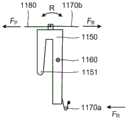
输注装置内部结构主要包括一个储药单元1110、活塞1120、螺杆1130、驱动轮1140、至少一个驱动单元1150、转轴1160、复位单元、动力单元1180与输注管(未示出)。下文将详细叙述输注管。在本发明的实施例中,驱动单元1150分别与复位单元和动力单元1180连接(在这里,连接包括机械连接或者电连接)。The internal structure of the infusion device mainly includes a
储药单元1110用于存储药物。药物包括但不限于胰岛素、胰高血糖素、抗生素、营养液、镇痛药、吗啡、抗凝血剂、基因治疗药物、心血管药物或化疗药物等。储药单元1110包括药物出口20。The
活塞1120用于将液体药物输注到体内。
螺杆1130分别与活塞1120和驱动轮1140相连接。在本发明实施例中,驱动轮1140通过转动以螺纹的方式驱动螺杆1130前进,进而推动设置于储药单元1110中的活塞1120向前运动,以达到输注药物的目的。The
驱动轮1140的圆周表面设置有轮齿1141。轮齿1141为齿轮齿或者棘轮齿。具体的,在本发明实施例中,轮齿1141为棘轮齿。棘轮齿能够更容易被推动,驱动效率较高。The circumferential surface of the
驱动单元1150包括至少一个驱动部1151,用于推动轮齿1141,进而推动驱动轮1140转动。驱动单元1150与转轴1160活动连接。在本发明实施例中,驱动单元1150包括一个驱动部1151。The
复位单元和动力单元1180相互配合使驱动单元1150绕着转轴1160往复转动,如图1中R方向所示,并且使驱动部1151在前进方向和复位方向运动。驱动单元1150进行一次往复转动,驱动轮1140驱动螺杆1130前进一个步长,进而推动活塞1120完成一次药物输注。The reset unit and the
复位单元包括弹性复位部件1170a和线性驱动复位部件1170b,即输注装置中同时设置弹性复位部件1170a和线性驱动复位部件1170b以控制驱动部1151的复位运动。在本发明的实施例中,首先,弹性复位部件1170a可以单独工作控制驱动部1151复位,也可以与线性驱动复位部件1170b协调配合共同控制驱动部1151复位,增加驱动部1151复位运动方式的多样性,提升了输注装置在驱动方式上的灵活度。其次,当弹性复位部件1170a发生故障时,为了不影响输注,输注装置可切换到线性驱动复位部件1170b进行工作。即线性驱动复位部件1170b作为弹性复位部件1170a的备份结构,提高了输注装置的可靠性。第三,弹性复位部件1170a和线性驱动复位部件1170b可以同时工作,协调配合。弹性复位部件1170a的复位弹力有限,但线性驱动复位部件1170b可控制其输出复位动力的大小。因此,与只有弹性复位部件1170a的复位单元相比,在弹性复位部件1170a和线性驱动复位部件1170b的协调配合下,驱动部1151可以复位更多个轮齿1141,使输注装置具备多种不同的输注模式,如不同的输注速率、不同的单位输注量等。第四,与只有线性驱动复位部件1170b的复位单元相比,两者协调配合减小了驱动部1151在复位时的电能消耗,降低了输注装置的功耗。The reset unit includes an
在这里需要说明的是,驱动部1151的前进方向是指推动轮齿1141运动的方向。驱动部1151的复位方向与前进方向相反。在复位时,驱动部1151只在轮齿1141表面滑动,不实施推动。It should be noted here that the forward direction of the driving
弹性复位部件1170a至少包括弹簧、弹片、弹性板、弹性棒、弹性复位橡胶等弹性件。在这里,弹簧包括压缩弹簧、拉伸弹簧或者扭力弹簧等。优选的,弹性复位部件1170a为弹簧。具体的,在本发明实施例中,弹性复位部件1170a为扭力弹簧。扭力弹簧更利于驱动单元1150复位转动。当复位单元为弹性复位部件1170a时,复位单元不需要消耗额外的能量即可工作,降低了输注装置的功耗,节约了生产成本。The
线性驱动复位部件1170b包括形状记忆合金等电驱动型线性驱动器或者电加热型线性驱动器。通电后,形状记忆合金等线性驱动器的物理形态发生变化,形状记忆合金发生收缩形变,输出动力。电流越大,形状记忆合金的收缩形变量越大,动力就越大。明显的,当电流恒定,形状记忆合金的形变量恒定,其输出的动力也就恒定。因此,形状记忆合金等线性驱动器能够输出稳定且可控的动力。The linear drive reset
需要说明的是,本发明的实施例并不限制弹性复位部件1170a与线性驱动复位部件1170b的位置,只要能够满足使驱动部1151复位运动的条件即可。It should be noted that the embodiments of the present invention do not limit the positions of the
动力单元1180为电驱动型线性驱动器或者电加热型线性驱动器。通过交替通断电,动力单元1180输出或停止输出动力。具体的,在本发明实施例中,动力单元1180为形状记忆合金。The
优选的,在本发明实施例中,输注装置还包括程序单元(未示出)。程序单元分别与动力单元1180和线性驱动复位部件1170b相连接,根据输注需求,程序单元控制动力单元1180或线性驱动复位部件1170b输出力的作用。Preferably, in the embodiment of the present invention, the infusion device further includes a program unit (not shown). The program unit is respectively connected with the
图2a-图2c为本发明不同实施例驱动部1151推动轮齿1141运动的俯视结构示意图。图3a-图3c为本发明不同实施例动力单元1180、复位单元分别与驱动单元1150互相配合的结构示意图。2a-2c are schematic top view structural diagrams of the driving
如图2a和图2b所示,本发明实施例的复位单元中只有弹性复位部件1170a起作用。驱动单元1150往复转动的原理如下:当动力单元1180以FP拉动驱动单元1150时,驱动单元1150绕着转轴1160逆时针转动,且可以带动驱动部1151推动轮齿1141前进,驱动轮1140向前进方向转动,进而驱动螺杆1130向DA方向前进。弹性复位部件1170a产生逐渐增强的弹力FR。当动力单元1180停止提供动力时,弹性复位部件1170a单独对驱动单元1150施加动力,驱动单元1150在弹力FR的单独作用下绕着转轴1160顺时针转动。此时,驱动部1151停止推动轮齿1141,而在轮齿1141表面滑动,驱动轮1140停止转动。驱动单元1150完成一次往复转动。As shown in Fig. 2a and Fig. 2b, in the reset unit of the embodiment of the present invention, only the
如图2b所示,在本发明的另一个实施例中,弹性复位部件1170a和动力单元1180均设置于转轴1160的一侧。且根据常规的技术原理,本领域技术人员可以调整弹性复位部件1170a、驱动单元1150以及动力单元1180的位置关系以及彼此的连接关系,在这里并不作具体限制,只要能够满足上述转动的条件即可。As shown in FIG. 2 b , in another embodiment of the present invention, the
如图2c所示,在本发明的又一个实施例中,弹性复位部件1170a和线性驱动复位部件1170b(复位单元)共同起作用。此时,复位单元单独向驱动单元1150输出复位动力。驱动部1151推动轮齿1141的原理与前文一致。但驱动部1151停止前进后,弹性复位部件1170a和线性驱动复位部件1170b(复位单元)分别提供复位动力FR和FB。FP与FR、FB的方向相反,弹性复位部件1170a和线性驱动复位部件1170b与动力单元1180互相配合使驱动单元1150往复转动。As shown in FIG. 2c, in yet another embodiment of the present invention, the
需要说明的是,弹性复位部件1170a或者弹性复位部件1170a与线性驱动复位部件1170b单独向驱动单元1150输出复位动力是指只有复位单元单独输出动力,动力单元不输出动力。It should be noted that the
优选的,如图2a-图2c所示,在本发明实施例中,FP的方向和FR、FB、DA的方向均平行。这样的平行设计充分利用输注装置内部的空间和结构关系,使内部结构更紧凑。Preferably, as shown in Fig. 2a-Fig. 2c, in the embodiment of the present invention, the direction ofFP is parallel to the directions ofFR , FB andDA . Such a parallel design makes full use of the internal space and structural relationship of the infusion device, making the internal structure more compact.
明显的,本领域技术人员可以根据需要调整的FP与FR、FB方向,只要能够满足使驱动单元1150往复转动的条件即可,如图3a-图3c所示。Obviously, those skilled in the art can adjust the directions of FP ,FR , and FB as required, as long as the conditions for reciprocating rotation of the
在本发明的其它实施例中,FP的方向和FR、FB的方向或DA的方向也可以不平行,这里并不作具体限制,只要能够达到使驱动单元1150往复转动的目的即可。In other embodiments of the present invention, the direction ofFP may not be parallel to the direction ofFR , FB orDA , and there is no specific limitation here, as long as the purpose of reciprocating rotation of the
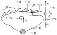
图4a和图4b为动力单元1180拉力方向与螺杆1130前进方向不平行的结构示意图。图4b为图4a的俯视图。FIG. 4a and FIG. 4b are structural schematic diagrams in which the pulling force direction of the
动力单元1180拉力FP的方向与螺杆1130前进方向DA垂直。转轴1160设置在底座上。如上文所述,驱动单元1150在R方向的往复转动可带动驱动部1151推动轮齿1141,使驱动轮1140向W方向转动,进而驱动螺杆1130在DA方向上前进。驱动单元1150的驱动原理与前文一致。The direction of the pulling force FP of the
在本发明实施例中,输注装置内还设置有能使驱动单元1150停止旋转的挡墙1171和1172(如图1和图2a中所示)。驱动单元1150与挡墙1171或1172接触触发电信号,以使程序单元控制动力单元1180动力的输出。在本发明的另一个实施例中,可以只设置挡墙1171或者只设置挡墙1172,驱动单元1150在某一侧的转动终点由程序单元控制。本发明实施例对挡墙1171或1172的位置不作具体限制,只要满足使驱动单元1150停止转动的条件即可。In the embodiment of the present invention, retaining
本发明的又一个实施例也可以不设置挡墙(如图2b-图4b所示),驱动单元1150的转动终点完全由程序单元控制。Still another embodiment of the present invention may not set a retaining wall (as shown in Fig. 2b-Fig. 4b), and the end point of rotation of the
图5、图6为本发明不同实施例输注装置包括两个驱动单元的结构示意图,每个驱动单元只包括一个驱动部。Fig. 5 and Fig. 6 are structural schematic diagrams of infusion devices including two driving units according to different embodiments of the present invention, and each driving unit only includes one driving part.
需要说明的是,为了清晰展示驱动单元的设置方式,图5与图6未示出复位单元。复位单元与驱动单元的位置关系、以及复位单元的工作原理请参考前文所述。It should be noted that, in order to clearly show the arrangement of the driving unit, FIG. 5 and FIG. 6 do not show the reset unit. For the positional relationship between the reset unit and the drive unit, and the working principle of the reset unit, please refer to the above.
如图5所示,驱动单元1250a在动力单元1280a和复位单元的作用下绕着转轴1260在R方向往复转动。同样,驱动单元1250b在动力单元1280b和复位单元的作用下绕着转轴1260在R方向往复转动。在本发明实施例中,两个驱动单元的旋转互不干扰,且驱动单元1250a和驱动单元1250b均可独立实施上文所述的驱动方式。As shown in FIG. 5 , the
优选的,在本发明实施例中,驱动单元1250a和驱动单元1250b非同步旋转。即,当驱动单元1250a的驱动部1251a推动轮齿1241运动时,驱动单元1250b的驱动部1251b在轮齿1241表面滑动。当驱动部1251b滑动至某一位置后,程序单元控制动力单元1280a停止对驱动单元1250a输出动力,转而控制动力单元1280b对驱动单元1250b输出动力。此时,驱动单元1250a在复位单元作用下沿顺时针方向转动,驱动部1251a在轮齿表面滑动,而驱动部1251b推动轮齿1241。依次交替推动,进而驱动单元1250a和1250b完成对同一个驱动轮1240的交替推动。两个驱动交替推动轮齿能够提高输注效率,且同时使输注装置具备多种输注模式。Preferably, in the embodiment of the present invention, the
在本发明的实施例中,动力单元1280a和1280b拉力FP、复位动力的方向以及螺杆1230前进方向DA如前文所述,且拉力FP的方向和螺杆1230前进方向DA平行。In the embodiment of the present invention, the direction of the pulling force FP of the
如图6所示,驱动部1351a和1351b分别交替推动轮齿1341,动力单元1380a和1380b的动力输出均由程序单元控制。As shown in FIG. 6 , the driving
需要说明的是,在本发明实施例中,动力单元1380a的拉力FP’的方向和动力单元1380b的拉力FP”的方向相反。It should be noted that, in the embodiment of the present invention, the direction of the pulling forceFP ' of the
驱动单元1350a和1350b非同步旋转。即,当驱动单元1350a的驱动部1351a推动轮齿1341前进时,驱动单元1350b的驱动部1351b在轮齿1341表面滑动。当驱动部1351b滑动至某一位置后,程序单元控制动力单元1380a停止对驱动单元1350a输出动力,转而控制动力单元1380b对驱动单元1350b输出动力,驱动单元1350a在复位单元作用下沿顺时针方向复位转动,驱动部1351a在轮齿1341表面滑动,而驱动部1351b推动轮齿1341。依次交替推动,驱动单元1350a和1350b完成对驱动轮1340的交替推动。The
同样的,驱动单元1350a和1350b均可独立实施上文所述的驱动方式。Likewise, both the driving
需要说明的是,在本发明的其它实施例中,驱动单元还可以包括更多个驱动单元,每个驱动单元上还可以包括更多个驱动部,或者驱动轮包括多个子轮,不同的驱动单元分别推动相应的子轮转动。It should be noted that, in other embodiments of the present invention, the driving unit may also include more driving units, and each driving unit may also include more driving parts, or the driving wheel may include multiple sub-wheels, different driving The units respectively push the corresponding sub-wheels to rotate.
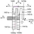
图7a和图7b为本发明一个实施例驱动单元1450的两个驱动部1451a和1451b分别与两个子轮1440a和1440b相互配合的结构示意图。图7b为图7a子轮1440a和1440b部分轮齿结构的右视图。Fig. 7a and Fig. 7b are structural schematic diagrams of two driving
如图7a和图7b所示,在本发明实施例中,驱动单元1450包括两个左右设置的驱动部1451a和1451b。驱动轮包括两个左右设置且固定连接的子轮1440a和1440b(即两个子轮可以同步前进)。驱动部1451a和1451b可分别推动子轮1440a和1440b转动。转轴1460设置于两个子轮1440a和1440b的同一侧。本发明实施例驱动部1451a或1451b均能推动轮齿1441a或1441b前进,其工作原理、运作方式与前文一致,在此不再赘述。As shown in Fig. 7a and Fig. 7b, in the embodiment of the present invention, the
除了每一个驱动部1451a或1451b单独实施推动,本发明实施例还可以通过调整驱动部1451a和1451b前端之间的距离,或者调整轮齿1441a和1441b的交错程度使两个驱动部1451a和1451b相配合运作。优选的,在本发明实施例中,轮齿1441a和1441b交错设置,交错程度为t,如图7a和图7b所示。In addition to pushing each driving
明显的,在本发明实施例中,两个驱动部1451a和1451b同步往复运动。如图7a所示,上一次前进动作结束后,驱动单元1450开始复位转动,驱动部1451a比驱动部1451b先到达驱动位置,驱动单元1450可改用驱动部1451a开始下一次前进动作。或者驱动单元1450可以继续复位转动,直至驱动部1451b到达下一个驱动位置开始下一次前进动作。Obviously, in the embodiment of the present invention, the two driving
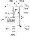
图8a和图8b为本发明再一个实施例驱动单元1550包括两个上下设置驱动部1551a和1551b,且驱动部1551a和1551b与同一个驱动轮1540相互配合的结构示意图。图8b为图8a中驱动单元1550的立体结构图。Fig. 8a and Fig. 8b are structural schematic diagrams of another embodiment of the present invention in which the
如图8a和图8b所示,驱动单元1550包括两个上下设置的驱动部1551a和1551b,且两者与同一个驱动轮1540相互配合,驱动部1551a和1551b同步往复运动。驱动部1551a和1551b的前端不平齐,如两者相距一定距离m,使两者不能同时推动轮齿1541前进,如图8a所示。当驱动部1551b结束上一次前进动作后,驱动单元1550进行复位转动,驱动部1551a比驱动部1551b先到达下一个驱动位置,驱动单元1550可改用驱动部1551a推动轮齿1541前进,开始下一次前进动作。或者驱动单元1550继续复位转动,直至驱动部1551b到达下一个驱动位置,开始下一次前进动作。As shown in Fig. 8a and Fig. 8b, the
在本发明的其他实施例中,驱动单元还可以包括更多个驱动部,如3个、4个或者更多个,在此不作具体限制。In other embodiments of the present invention, the driving unit may further include more driving parts, such as 3, 4 or more, which is not specifically limited here.
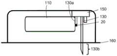
图9a-图9b分别为本发明实施例输注装置装配结构150在初始位置和工作位置的结构示意图。图9c为本发明实施例部分输注管130设置于装配结构150内的结构示意图。9a-9b are structural schematic diagrams of the
如前文所述,本发明实施例的输注装置还包括输注管130。输注管130作为药物输注通道。输注管130包括连接端130a和皮下端130b。当连接端130a与药物出口20连通,皮下端130b进入皮下,药物可通过输注管130输入皮下。As mentioned above, the infusion device of the embodiment of the present invention further includes an
需要说明的是,连接端130a与药物出口20连通的方式,或者皮下端130b进入皮下的方式可以有多种,或者两个步骤的顺序可以不同,在这里并不做具体限制。It should be noted that there may be various ways for the
输注管130包括硬针或者软管。使用硬针能够提高输注管130的强度。使用软管能够提高输注管130位置设计的灵活度。具体的,在本发明实施例中,输注管130整体为硬针。在本发明的另一个实施例中,输注管130整体为软管。The
在本发明的又一个实施例中,输注管130包括互相连接的硬针和软管。即输注管130包括多个部分。如连接端130a为硬针,皮下端130b为软管;或者连接端130a为软管,皮下端130b为硬针,提高了输注装置结构设计的灵活度。In yet another embodiment of the present invention, the
在本发明的再一个实施例中,连接端130a与皮下端130b同为硬针或者同为软管。此时,连接连接端130a与皮下端130b的部分可以是硬针或者软管,或者是带有空腔的封闭结构,即连接端130a、皮下端130b和这里所述的连接部分共同构成输注管130,在这里并不作具体限制。In yet another embodiment of the present invention, the connecting
在本发明实施例中,输注装置还包括装配结构150。输注管130的一部分设置于装配结构150中,如图9c所示。当位于初始位置时,装配结构150凸出于输注装置外壳表面,且连接端130a未与药物出口20连通,皮下端130b未进入皮下,如图9a所示。当从初始位置被安装至工作位置时,装配结构150进入输注装置内,其顶部与输注装置壳体成为一体结构,且连接端130a与药物出口20连通,皮下端130b进入皮下,如图9b所示。明显的,在本发明实施例中,装配结构150携带着输注管130整体同步运动。In the embodiment of the present invention, the infusion set further includes an
用户在使用之前,装配结构150携带着输注管130处于初始位置。在使用时,通过医用胶布160将输注装置贴在人体表面后,用户按下装配结构150完成安装操作,输注管130成为连通体液与储药单元1110桥梁,输注装置可开始正常工作。相比于输注管130的其他安装方法,本发明实施例的安装方法减少用户在安装时的操作步骤,使安装更便捷和灵活,改善了用户体验。Before the user uses, the
输注管130在装配结构150中的设置方式可以有多种,在这里不做具体限制。具体的,在本发明的另一个实施例中,装配结构150可被控制自动从初始位置安装到工作位置,而非手动操作。The
在本发明的另一个实施例中,皮下端130b为软管,当装配结构150被安装到工作位置后,皮下端130b由用户手动刺入皮下。在本发明的又一个实施例中,皮下端130b为软管,用户可先将皮下端130b刺入皮下,再将装配结构150安装至工作位置,使得连接端130a与药物出口20连通。In another embodiment of the present invention, the
需要说明的是,在本发明的其他实施例中,还可以不设置装配结构150,而是输注管130直接固定设置于输注装置中。当输注装置粘贴在皮肤的同时,皮下端130b刺入皮下。It should be noted that, in other embodiments of the present invention, the
图10为本发明实施例药物出口20、过渡连通件30与输注管130互相连接的结构示意图。Fig. 10 is a structural schematic diagram of the interconnection of the
本发明施例还包括过渡连通件30。过渡连通件30设置于药物出口20外侧,其一端与药物出口20连通。在本发明的一些实施例中,由于输注管130并非与药物出口20一直相连接,因此设置过渡连通件30能够避免药物泄露。具体的,在本发明实施例中,过渡连通件30为一个连通腔体。当装配装置150安装至工作位置时,连接端130a进入连通腔体内,实现与药物出口20的连通。Embodiments of the present invention also include a
在本发明另一个实施例中,过渡连通件30为一个连通接口。当装配装置150被安装至工作位置时,连接端130a与连通接口相连接,实现与药物出口20的连通。In another embodiment of the present invention, the
需要说明的是,过渡连通件30为储药单元1110的一部分或者是单独的结构,这里并不作具体限制。It should be noted that the
综上所述,本发明提供了一种高可靠性单边驱动药物输注装置,复位单元既包括弹性复位部件,也包括线性驱动复位部件,弹性复位部件可以单独运作,也可以与线性驱动复位部件协同配合,提高了输注装置的可靠性,增加了用户选择的灵活度。In summary, the present invention provides a high-reliability unilaterally driven drug infusion device. The reset unit includes both an elastic reset component and a linear drive reset component. The elastic reset component can operate alone or can be reset with a linear drive. The coordinated cooperation of the components improves the reliability of the infusion device and increases the flexibility of user selection.
虽然已经通过示例对本发明的一些特定实施例进行了详细说明,但是本领域的技术人员应该理解,以上示例仅是为了进行说明,而不是为了限制本发明的范围。本领域的技术人员应该理解,可在不脱离本发明的范围和精神的情况下,对以上实施例进行修改。本发明的范围由所附权利要求来限定。Although some specific embodiments of the present invention have been described in detail through examples, those skilled in the art should understand that the above examples are for illustration only, rather than limiting the scope of the present invention. Those skilled in the art will appreciate that modifications can be made to the above embodiments without departing from the scope and spirit of the invention. The scope of the invention is defined by the appended claims.
Claims (11)
Applications Claiming Priority (3)
| Application Number | Priority Date | Filing Date | Title |
|---|---|---|---|
| PCT/CN2019/087342WO2020232565A1 (en) | 2019-05-17 | 2019-05-17 | Drug infusion device |
| CNPCT/CN2019/130442 | 2019-12-31 | ||
| PCT/CN2019/130442WO2020233128A1 (en) | 2019-05-17 | 2019-12-31 | Miniature patch-type intelligent control infusion device |
Publications (2)
| Publication Number | Publication Date |
|---|---|
| CN113117190A CN113117190A (en) | 2021-07-16 |
| CN113117190Btrue CN113117190B (en) | 2023-02-17 |
Family
ID=73336493
Family Applications (7)
| Application Number | Title | Priority Date | Filing Date |
|---|---|---|---|
| CN201980093472.7AActiveCN113543823B (en) | 2019-05-17 | 2019-05-17 | Drug infusion device |
| CN201911413566.6AActiveCN111939371B (en) | 2019-05-17 | 2019-12-31 | Micro patch intelligent control infusion device |
| CN202010723618.6AActiveCN113117190B (en) | 2019-05-17 | 2020-07-24 | High-reliability single-side driving drug infusion device |
| CN202011196301.8AActiveCN114146252B (en) | 2019-05-17 | 2020-10-30 | Infusion needle structure of medicine infusion device |
| CN202110710446.3AActiveCN114146254B (en) | 2019-05-17 | 2021-06-25 | Infusion needle structure of medicine infusion device |
| CN202121610356.9UActiveCN215961542U (en) | 2019-05-17 | 2021-07-15 | Unilaterally actuated drug infusion device |
| CN202110801124.XAActiveCN114146251B (en) | 2019-05-17 | 2021-07-15 | Single-side driven drug infusion device |
Family Applications Before (2)
| Application Number | Title | Priority Date | Filing Date |
|---|---|---|---|
| CN201980093472.7AActiveCN113543823B (en) | 2019-05-17 | 2019-05-17 | Drug infusion device |
| CN201911413566.6AActiveCN111939371B (en) | 2019-05-17 | 2019-12-31 | Micro patch intelligent control infusion device |
Family Applications After (4)
| Application Number | Title | Priority Date | Filing Date |
|---|---|---|---|
| CN202011196301.8AActiveCN114146252B (en) | 2019-05-17 | 2020-10-30 | Infusion needle structure of medicine infusion device |
| CN202110710446.3AActiveCN114146254B (en) | 2019-05-17 | 2021-06-25 | Infusion needle structure of medicine infusion device |
| CN202121610356.9UActiveCN215961542U (en) | 2019-05-17 | 2021-07-15 | Unilaterally actuated drug infusion device |
| CN202110801124.XAActiveCN114146251B (en) | 2019-05-17 | 2021-07-15 | Single-side driven drug infusion device |
Country Status (4)
| Country | Link |
|---|---|
| US (6) | US12403247B2 (en) |
| EP (6) | EP3970767B1 (en) |
| CN (7) | CN113543823B (en) |
| WO (8) | WO2020232565A1 (en) |
Families Citing this family (14)
| Publication number | Priority date | Publication date | Assignee | Title |
|---|---|---|---|---|
| US12403247B2 (en)* | 2019-05-17 | 2025-09-02 | Medtrum Technologies Inc. | Drug infusion device |
| US11458292B2 (en) | 2019-05-20 | 2022-10-04 | Unomedical A/S | Rotatable infusion device and methods thereof |
| US20220218895A1 (en)* | 2019-08-01 | 2022-07-14 | Medtrum Technologies Inc. | Driving apparatus and drug infusion device |
| EP4093460A4 (en)* | 2020-01-21 | 2023-09-27 | Medtrum Technologies Inc. | Medical device with safety verification and safety verification method thereof |
| EP4251236A4 (en)* | 2020-11-27 | 2024-10-30 | Medtrum Technologies Inc. | A driving structure of a drug infusion device |
| CN114558198B (en)* | 2020-11-27 | 2024-07-02 | 上海移宇科技股份有限公司 | Driving structure of drug infusion device |
| WO2022109967A1 (en)* | 2020-11-27 | 2022-06-02 | Medtrum Technologies Inc. | A driving structure of a drug infusion device |
| WO2022147985A1 (en)* | 2021-01-05 | 2022-07-14 | Medtrum Technologies Inc. | A skin patch drug infusion device |
| US20240115799A1 (en)* | 2021-01-05 | 2024-04-11 | Medtrum Technologies Inc. | Skin patch drug infusion device |
| US20240115800A1 (en)* | 2021-01-05 | 2024-04-11 | Medtrum Technologies Inc. | Drug infusion device with security base |
| CN115887813B (en)* | 2021-08-06 | 2025-03-14 | 上海移宇科技有限公司 | Drug infusion device without half-press |
| CN115779184A (en)* | 2021-09-10 | 2023-03-14 | 上海移宇科技股份有限公司 | Interlocking type medicine infusion device |
| US20230372632A1 (en)* | 2022-05-22 | 2023-11-23 | Altek Biotechnology Corporation | Driving mechanism for driving a plunger of an auto-injector to slide relative to a reservoir of the auto-injector and auto-injector therewith |
| CN115252304A (en)* | 2022-08-11 | 2022-11-01 | 南京市江宁医院 | A medical infusion oxygen delivery device |
Citations (2)
| Publication number | Priority date | Publication date | Assignee | Title |
|---|---|---|---|---|
| CN103260678A (en)* | 2010-12-22 | 2013-08-21 | 爱尔康研究有限公司 | Device for at least one of infusing and aspirating |
| CN106110445A (en)* | 2016-08-12 | 2016-11-16 | 上海移宇科技股份有限公司 | A kind of infusion system of portable medication infusion device |
Family Cites Families (97)
| Publication number | Priority date | Publication date | Assignee | Title |
|---|---|---|---|---|
| US2270804A (en)* | 1940-07-18 | 1942-01-20 | Samson R Dutky | Microinjector |
| US4562751A (en)* | 1984-01-06 | 1986-01-07 | Nason Clyde K | Solenoid drive apparatus for an external infusion pump |
| US4602700A (en)* | 1984-06-15 | 1986-07-29 | Daltex Medical Sciences, Inc. | Fail-safe mechanical drive for syringe |
| NL9101489A (en)* | 1991-09-03 | 1993-04-01 | Texas Instruments Holland | INJECTOR FOR IMMEDIATELY IMPLANTING AN OBJECT IN A LIVING BEING. |
| DE4133402C1 (en)* | 1991-10-09 | 1993-01-07 | B. Braun Melsungen Ag, 3508 Melsungen, De | Medical pressure infusion appts. - has slidable holder pressing out syringe held in holder fixed to housing with selective motor or manual drive |
| JP4425465B2 (en)* | 1998-03-23 | 2010-03-03 | エラン コーポレーション ピーエルシー | Drug delivery device |
| CN2402333Y (en)* | 1999-12-24 | 2000-10-25 | 王秀琪 | Open-loop continuous insulin subcutaneous transfusion device |
| US6554800B1 (en)* | 2000-08-09 | 2003-04-29 | Medtronic Minimed, Inc. | Compact pump motor system and dispensing process |
| JP3931060B2 (en)* | 2001-08-08 | 2007-06-13 | Ntn株式会社 | Syringe pump lead screw and syringe pump |
| GB0201689D0 (en)* | 2002-01-25 | 2002-03-13 | Dca Design Consultants Ltd | Improvements in and relating to a medicament injection device |
| US20050238507A1 (en)* | 2002-04-23 | 2005-10-27 | Insulet Corporation | Fluid delivery device |
| US6656158B2 (en)* | 2002-04-23 | 2003-12-02 | Insulet Corporation | Dispenser for patient infusion device |
| US20040153032A1 (en) | 2002-04-23 | 2004-08-05 | Garribotto John T. | Dispenser for patient infusion device |
| AU2003245872A1 (en)* | 2002-07-24 | 2004-02-09 | M 2 Medical A/S | An infusion pump system, an infusion pump unit and an infusion pump |
| DE10240165A1 (en)* | 2002-08-30 | 2004-03-18 | Disetronic Licensing Ag | Dispensing unit for use in infusion pumps comprises reservoir for infusion liquid fitted with spring-loaded piston, toothed wheel cooperating with locking bar to prevent piston moving |
| US7144384B2 (en)* | 2002-09-30 | 2006-12-05 | Insulet Corporation | Dispenser components and methods for patient infusion device |
| EP1556103A1 (en)* | 2002-10-07 | 2005-07-27 | Novo Nordisk A/S | Needle device comprising a plurality of needles |
| DE60336834D1 (en)* | 2002-10-09 | 2011-06-01 | Abbott Diabetes Care Inc | FUEL FEEDING DEVICE, SYSTEM AND METHOD |
| WO2004056412A2 (en)* | 2002-12-23 | 2004-07-08 | M2 Medical A/S | A disposable, wearable insulin dispensing device, a combination of such a device and a programming controller and a method of controlling the operation of such a device |
| EP1502613A1 (en)* | 2003-08-01 | 2005-02-02 | Novo Nordisk A/S | Needle device with retraction means |
| CN1863566B (en)* | 2003-08-12 | 2010-09-01 | 贝克顿·迪金森公司 | Patch-like infusion device |
| US7682358B2 (en)* | 2003-10-30 | 2010-03-23 | Medtronic, Inc. | Steerable catheter |
| US7731691B2 (en)* | 2003-11-10 | 2010-06-08 | Smiths Medical Asd, Inc. | Subcutaneous infusion device and device for insertion of a cannula of an infusion device and method |
| WO2006078817A2 (en)* | 2005-01-21 | 2006-07-27 | Medrad, Inc. | Injectors, injector systems and methods for injecting fluids |
| US8167841B2 (en)* | 2005-01-24 | 2012-05-01 | Novo Nordisk A/S | Transcutaneous device assembly |
| CN101208515A (en) | 2005-03-28 | 2008-06-25 | 因苏雷特公司 | Fluid delivery device |
| EP1877115A1 (en)* | 2005-04-06 | 2008-01-16 | M 2 Medical A/S | An actuator |
| US7534226B2 (en)* | 2005-09-26 | 2009-05-19 | M2 Group Holdings, Inc. | Dispensing fluid from an infusion pump system |
| US7682338B2 (en)* | 2006-08-23 | 2010-03-23 | Medtronic Minimed, Inc. | Infusion medium delivery system, device and method with needle inserter and needle inserter device and method |
| US20100152660A1 (en)* | 2007-05-30 | 2010-06-17 | Eli Lilly And Company | Cartridge with multiple injection needles for a medication injection device |
| EP2263720B1 (en) | 2007-08-20 | 2012-06-13 | Mallinckrodt LLC | Fluid driven medical injectors |
| EP2200677A1 (en)* | 2007-09-17 | 2010-06-30 | ICU Medical, Inc. | Insertion devices for infusion devices |
| CN101138659A (en)* | 2007-09-27 | 2008-03-12 | 无锡顶点医疗器械有限公司 | Insulin pump |
| BRPI0817907B8 (en)* | 2007-10-02 | 2021-06-22 | Lamodel Ltd | apparatus for administering a substance to an individual |
| US7922695B2 (en)* | 2007-10-18 | 2011-04-12 | Roche Diagnostics Operations, Inc. | Drug delivery pump drive using linear piezoelectric motor |
| US7862534B2 (en)* | 2008-06-11 | 2011-01-04 | Bracco Diagnostics Inc. | Infusion circuit subassemblies |
| US8231577B2 (en)* | 2008-06-26 | 2012-07-31 | Calibra Medical, Inc. | Disposable infusion device with automatically releasable cannula driver |
| EP2165722A1 (en)* | 2008-09-19 | 2010-03-24 | F.Hoffmann-La Roche Ag | Device for feeding a product in a medical or pharmaceutical application |
| US9101706B2 (en)* | 2009-10-13 | 2015-08-11 | Valeritas, Inc. | Fluid delivery device |
| AU2010325518A1 (en)* | 2009-11-30 | 2012-06-14 | F.Hoffmann-La Roche Ag | Analyte monitoring and fluid dispensing system |
| CN201701000U (en)* | 2010-03-08 | 2011-01-12 | 九阳股份有限公司 | Safety electric cooker |
| KR20130018783A (en)* | 2010-03-30 | 2013-02-25 | 우노메디컬 에이/에스 | Medical device |
| JP5471890B2 (en)* | 2010-06-28 | 2014-04-16 | 住友電装株式会社 | Charging connector |
| CA2813470A1 (en)* | 2010-10-25 | 2012-05-03 | Sanofi-Aventis Deutschland Gmbh | Medicine delivery device |
| CN102600526B (en) | 2012-03-09 | 2013-10-16 | 北京化工大学 | Intelligent micropump for switching between insulin infusion and glucagon infusion |
| US9463280B2 (en)* | 2012-03-26 | 2016-10-11 | Medimop Medical Projects Ltd. | Motion activated septum puncturing drug delivery device |
| EP2650031A1 (en)* | 2012-04-11 | 2013-10-16 | PharmaSens AG | Manual pressure activated application mechanism |
| DK3284493T3 (en)* | 2012-04-13 | 2020-11-02 | Becton Dickinson Co | Micro-infusion device with automatic needle retraction |
| CN202958118U (en)* | 2012-12-17 | 2013-06-05 | 莱恩农业装备有限公司 | Full-hydraulic drive two-dimensional horizontally-moving lifting type farm-oriented car frame |
| KR20140110496A (en)* | 2013-03-08 | 2014-09-17 | 삼성전자주식회사 | Drug infusion pump |
| US10080839B2 (en)* | 2013-03-14 | 2018-09-25 | Becton, Dickinson And Company | Angled inserter for drug infusion |
| US20140276413A1 (en)* | 2013-03-15 | 2014-09-18 | Jeff Baker | Medicament delivery and simulation system with a removable disposable container for medicament and a rotatable actuation component |
| US20140303559A1 (en)* | 2013-04-05 | 2014-10-09 | William Marsh Rice University | Automatic syringe pumps for drug and fluid delivery |
| DK2983746T3 (en) | 2013-04-10 | 2020-03-23 | Sanofi Sa | INJECTION DEVICE AND PROCEDURE FOR COLLECTION |
| US20140378903A1 (en)* | 2013-06-21 | 2014-12-25 | Animas Corporation | Manually actuated infusion device and dose counter |
| CN103948980B (en)* | 2014-04-04 | 2017-02-15 | 赵立生 | Novel infusion apparatus |
| WO2015158230A1 (en)* | 2014-04-14 | 2015-10-22 | 江苏多维科技有限公司 | Micro guiding screw pump using magnetic resistance sensor and manufacturing method therefor |
| EP4585239A3 (en)* | 2014-04-24 | 2025-10-15 | Becton, Dickinson and Company | Catheter insertion device |
| US9731067B2 (en)* | 2014-11-25 | 2017-08-15 | Medtronic Minimed, Inc. | Mechanical injection pump and method of use |
| JP2017536959A (en) | 2014-12-08 | 2017-12-14 | サノフイ | Drug delivery device |
| JP6716566B2 (en)* | 2014-12-19 | 2020-07-01 | アムジエン・インコーポレーテツド | Drug delivery device with proximity sensor |
| EA036104B1 (en)* | 2015-03-09 | 2020-09-29 | Эмджен Инк. | Drive mechanisms for drug delivery pumps |
| CN106267463A (en)* | 2015-05-25 | 2017-01-04 | 美敦力公司 | Portable fluid infusion apparatus and manufacture method thereof including actuating device |
| US9993594B2 (en)* | 2015-06-22 | 2018-06-12 | Medtronic Minimed, Inc. | Occlusion detection techniques for a fluid infusion device having a rotary pump mechanism and rotor position sensors |
| CN108136124B (en)* | 2015-10-05 | 2022-09-06 | 费森尤斯维尔公司 | Infusion device for administering a medical fluid to a patient and method for operating an infusion device |
| CN105343965B (en)* | 2015-10-28 | 2019-11-15 | 利辛县众善医药科技有限公司 | Infusion alarm system for infusion bag infusion model |
| CN205163805U (en)* | 2015-12-01 | 2016-04-20 | 北京大学第一医院 | Portable infusion device |
| WO2017134966A1 (en)* | 2016-02-04 | 2017-08-10 | テルモ株式会社 | Puncture device and method for retaining cannula |
| CN105680337B (en)* | 2016-04-15 | 2017-11-21 | 泉州市大西洋电力科技有限公司 | The emergency unlocking mechanism at high-voltage complete switch equipment back door |
| WO2017181324A1 (en)* | 2016-04-18 | 2017-10-26 | Medtrum Technologies Inc. | A unilateral driving mechanism for a portable infusion system |
| TWI746569B (en)* | 2016-06-08 | 2021-11-21 | 瑞士商瑞健醫療股份有限公司 | Dosiergerat, injektionsvorrichtung und verwendung |
| CA3030891A1 (en)* | 2016-07-27 | 2018-02-01 | Becton, Dickinson And Company | Infusion bump capture needle shield |
| JP6970733B2 (en)* | 2016-08-02 | 2021-11-24 | サノフィ−アベンティス・ドイチュラント・ゲゼルシャフト・ミット・ベシュレンクテル・ハフツング | Drug delivery device |
| CN106139311A (en)* | 2016-08-12 | 2016-11-23 | 上海移宇科技股份有限公司 | A kind of drug-supplying system comprising position detection unit |
| CN110248686B (en)* | 2016-09-27 | 2022-04-29 | 赛诺菲-安万特德国有限公司 | Medicament delivery device |
| US10780217B2 (en)* | 2016-11-10 | 2020-09-22 | Insulet Corporation | Ratchet drive for on body delivery system |
| CN108331731B (en)* | 2017-01-19 | 2020-08-21 | 达尔生技股份有限公司 | fluid delivery device |
| CN207627685U (en) | 2017-06-05 | 2018-07-20 | 丁平 | Fine-tuning Automatic-backing type helps note rifle |
| JP7126544B2 (en) | 2017-07-07 | 2022-08-26 | ニューロダーム リミテッド | Vial adapter, method and filling system for filling a reservoir of a drug delivery device with a flowable drug using the vial adapter |
| CN107456625B (en)* | 2017-09-12 | 2018-08-14 | 美敦力公司 | Fluid infusion apparatus and its drive system |
| CN207199865U (en)* | 2017-09-21 | 2018-04-06 | 深圳传音制造有限公司 | Electronic card latch-up structure and terminal device |
| CN111372629B (en)* | 2017-10-16 | 2022-09-30 | 贝克顿·迪金森公司 | End of dose detection for drug delivery systems |
| CN208049137U (en) | 2017-11-17 | 2018-11-06 | 金华芘丽芙美容医院股份有限公司 | A kind of roller type medical filling gun |
| CN108295335A (en)* | 2018-01-26 | 2018-07-20 | 美敦力公司 | Sticking type fluid infusion apparatus and infusion needle protector |
| CN110115784A (en)* | 2018-02-05 | 2019-08-13 | 郑州瑞宇科技有限公司 | A kind of insulin pump extrusion infusing pipeline |
| CN108273153B (en)* | 2018-03-14 | 2024-04-05 | 深圳中科光电医疗电子有限公司 | Self-destruction type precise transfusion device |
| CN108295338B (en)* | 2018-03-15 | 2020-07-03 | 青岛市第三人民医院 | Be applied to infusion pump's multistage flow control device |
| TWI682766B (en)* | 2018-07-27 | 2020-01-21 | 華廣生技股份有限公司 | Elastic physiological patch |
| CN108939203B (en) | 2018-08-23 | 2024-09-03 | 苏州新生命医疗科技有限公司 | Driving structure of drug infusion system and high-precision drug infusion system |
| CN109172934A (en)* | 2018-08-23 | 2019-01-11 | 苏州新生命医疗科技有限公司 | A kind of driving structure and drug infusion system of compact drug infusion system |
| CA3106452A1 (en)* | 2018-09-24 | 2020-04-02 | Amgen Inc. | Interventional dosing systems and methods |
| KR20190026730A (en)* | 2019-03-07 | 2019-03-13 | 이오플로우(주) | Apparatus for Infusing medical liquid |
| US12403247B2 (en)* | 2019-05-17 | 2025-09-02 | Medtrum Technologies Inc. | Drug infusion device |
| WO2021012075A1 (en)* | 2019-07-19 | 2021-01-28 | Medtrum Technologies Inc. | Integrated drug infusion device |
| WO2021012852A1 (en)* | 2019-07-19 | 2021-01-28 | Medtrum Technologies Inc. | Unilateral-driven medical device with infusion and detection integrated |
| US20220218895A1 (en)* | 2019-08-01 | 2022-07-14 | Medtrum Technologies Inc. | Driving apparatus and drug infusion device |
| CN110974477B (en)* | 2019-11-22 | 2022-10-28 | 张珂孟 | Injection device that animal husbandry used |
- 2019
- 2019-05-17USUS17/432,096patent/US12403247B2/enactiveActive
- 2019-05-17EPEP19929733.4Apatent/EP3970767B1/enactiveActive
- 2019-05-17WOPCT/CN2019/087342patent/WO2020232565A1/ennot_activeCeased
- 2019-05-17CNCN201980093472.7Apatent/CN113543823B/enactiveActive
- 2019-12-31WOPCT/CN2019/130442patent/WO2020233128A1/ennot_activeCeased
- 2019-12-31USUS17/432,095patent/US20220143304A1/enactivePending
- 2019-12-31EPEP19929277.2Apatent/EP3969078A4/enactivePending
- 2019-12-31CNCN201911413566.6Apatent/CN111939371B/enactiveActive
- 2020
- 2020-07-22EPEP20910894.3Apatent/EP4084842A4/enactivePending
- 2020-07-22USUS17/785,410patent/US20230011367A1/enactivePending
- 2020-07-22WOPCT/CN2020/103376patent/WO2021135173A1/ennot_activeCeased
- 2020-07-24CNCN202010723618.6Apatent/CN113117190B/enactiveActive
- 2020-09-08EPEP20911099.8Apatent/EP4084843A4/enactivePending
- 2020-09-08USUS17/785,406patent/US12427244B2/enactiveActive
- 2020-09-08WOPCT/CN2020/113980patent/WO2021135359A1/ennot_activeCeased
- 2020-09-15USUS17/924,119patent/US20230190186A1/enactivePending
- 2020-09-15EPEP20936044.5Apatent/EP4149587A4/enactivePending
- 2020-09-15WOPCT/CN2020/115206patent/WO2021227321A1/ennot_activeCeased
- 2020-10-30WOPCT/CN2020/125031patent/WO2022052248A1/ennot_activeCeased
- 2020-10-30CNCN202011196301.8Apatent/CN114146252B/enactiveActive
- 2021
- 2021-06-25CNCN202110710446.3Apatent/CN114146254B/enactiveActive
- 2021-06-25WOPCT/CN2021/102327patent/WO2022052573A1/ennot_activeCeased
- 2021-07-15CNCN202121610356.9Upatent/CN215961542U/enactiveActive
- 2021-07-15WOPCT/CN2021/106456patent/WO2022052621A1/ennot_activeCeased
- 2021-07-15USUS18/024,278patent/US20230256162A1/enactivePending
- 2021-07-15CNCN202110801124.XApatent/CN114146251B/enactiveActive
- 2021-07-15EPEP21865677.5Apatent/EP4210791A4/enactivePending
Patent Citations (2)
| Publication number | Priority date | Publication date | Assignee | Title |
|---|---|---|---|---|
| CN103260678A (en)* | 2010-12-22 | 2013-08-21 | 爱尔康研究有限公司 | Device for at least one of infusing and aspirating |
| CN106110445A (en)* | 2016-08-12 | 2016-11-16 | 上海移宇科技股份有限公司 | A kind of infusion system of portable medication infusion device |
Also Published As
Similar Documents
| Publication | Publication Date | Title |
|---|---|---|
| CN113117190B (en) | High-reliability single-side driving drug infusion device | |
| US12280240B2 (en) | Unilateral-driven drug infusion device | |
| CN112237660B (en) | Single-side driving drug infusion device | |
| CN113117182B (en) | Unilateral driving closed-loop artificial pancreas | |
| CN113663159B (en) | One-way drive drug infusion device | |
| CN111939387B (en) | Drug infusion device with multiple infusion modes | |
| WO2016085871A1 (en) | Mechanical injection pump and method of use | |
| CN103599578B (en) | A kind of handheld piezoelectric drives insulin pump | |
| CN114588389A (en) | Unilaterally actuated drug delivery system | |
| CN113117184B (en) | Unilateral drive patch drug infusion device | |
| WO2024011695A1 (en) | Driving reset type liquid medicine infusion device | |
| CN203564606U (en) | Portable piezoelectric driving insulin pump | |
| CN113082383A (en) | Injector and injection platform | |
| CN117679580A (en) | Insulin pump and infusion driving device thereof | |
| CN211705506U (en) | Micro-drug delivery device | |
| CN110882445A (en) | Micro-drug delivery device | |
| WO2024011696A1 (en) | Detachable drug liquid infusion device |
Legal Events
| Date | Code | Title | Description |
|---|---|---|---|
| PB01 | Publication | ||
| PB01 | Publication | ||
| SE01 | Entry into force of request for substantive examination | ||
| SE01 | Entry into force of request for substantive examination | ||
| GR01 | Patent grant | ||
| GR01 | Patent grant |