CN113116407B - Plugging device - Google Patents
Plugging deviceDownload PDFInfo
- Publication number
- CN113116407B CN113116407BCN201911404922.8ACN201911404922ACN113116407BCN 113116407 BCN113116407 BCN 113116407BCN 201911404922 ACN201911404922 ACN 201911404922ACN 113116407 BCN113116407 BCN 113116407B
- Authority
- CN
- China
- Prior art keywords
- sealing
- unit
- edge
- film body
- sealing unit
- Prior art date
- Legal status (The legal status is an assumption and is not a legal conclusion. Google has not performed a legal analysis and makes no representation as to the accuracy of the status listed.)
- Active
Links
Images


Classifications
- A—HUMAN NECESSITIES
- A61—MEDICAL OR VETERINARY SCIENCE; HYGIENE
- A61B—DIAGNOSIS; SURGERY; IDENTIFICATION
- A61B17/00—Surgical instruments, devices or methods
- A61B17/0057—Implements for plugging an opening in the wall of a hollow or tubular organ, e.g. for sealing a vessel puncture or closing a cardiac septal defect
- A—HUMAN NECESSITIES
- A61—MEDICAL OR VETERINARY SCIENCE; HYGIENE
- A61B—DIAGNOSIS; SURGERY; IDENTIFICATION
- A61B17/00—Surgical instruments, devices or methods
- A61B17/12—Surgical instruments, devices or methods for ligaturing or otherwise compressing tubular parts of the body, e.g. blood vessels or umbilical cord
- A61B17/12022—Occluding by internal devices, e.g. balloons or releasable wires
- A61B17/12099—Occluding by internal devices, e.g. balloons or releasable wires characterised by the location of the occluder
- A61B17/12122—Occluding by internal devices, e.g. balloons or releasable wires characterised by the location of the occluder within the heart
- A—HUMAN NECESSITIES
- A61—MEDICAL OR VETERINARY SCIENCE; HYGIENE
- A61B—DIAGNOSIS; SURGERY; IDENTIFICATION
- A61B17/00—Surgical instruments, devices or methods
- A61B17/12—Surgical instruments, devices or methods for ligaturing or otherwise compressing tubular parts of the body, e.g. blood vessels or umbilical cord
- A61B17/12022—Occluding by internal devices, e.g. balloons or releasable wires
- A61B17/12131—Occluding by internal devices, e.g. balloons or releasable wires characterised by the type of occluding device
- A61B17/12168—Occluding by internal devices, e.g. balloons or releasable wires characterised by the type of occluding device having a mesh structure
- A61B17/12172—Occluding by internal devices, e.g. balloons or releasable wires characterised by the type of occluding device having a mesh structure having a pre-set deployed three-dimensional shape
- A—HUMAN NECESSITIES
- A61—MEDICAL OR VETERINARY SCIENCE; HYGIENE
- A61B—DIAGNOSIS; SURGERY; IDENTIFICATION
- A61B17/00—Surgical instruments, devices or methods
- A61B17/0057—Implements for plugging an opening in the wall of a hollow or tubular organ, e.g. for sealing a vessel puncture or closing a cardiac septal defect
- A61B2017/00575—Implements for plugging an opening in the wall of a hollow or tubular organ, e.g. for sealing a vessel puncture or closing a cardiac septal defect for closure at remote site, e.g. closing atrial septum defects
- A61B2017/00623—Introducing or retrieving devices therefor
- A—HUMAN NECESSITIES
- A61—MEDICAL OR VETERINARY SCIENCE; HYGIENE
- A61B—DIAGNOSIS; SURGERY; IDENTIFICATION
- A61B17/00—Surgical instruments, devices or methods
- A61B17/12—Surgical instruments, devices or methods for ligaturing or otherwise compressing tubular parts of the body, e.g. blood vessels or umbilical cord
- A61B17/12022—Occluding by internal devices, e.g. balloons or releasable wires
- A61B2017/1205—Introduction devices
- A61B2017/12054—Details concerning the detachment of the occluding device from the introduction device
- A61B2017/12095—Threaded connection
Landscapes
- Health & Medical Sciences (AREA)
- Surgery (AREA)
- Life Sciences & Earth Sciences (AREA)
- Heart & Thoracic Surgery (AREA)
- Molecular Biology (AREA)
- Veterinary Medicine (AREA)
- Engineering & Computer Science (AREA)
- Biomedical Technology (AREA)
- Public Health (AREA)
- Medical Informatics (AREA)
- Nuclear Medicine, Radiotherapy & Molecular Imaging (AREA)
- Animal Behavior & Ethology (AREA)
- General Health & Medical Sciences (AREA)
- Reproductive Health (AREA)
- Vascular Medicine (AREA)
- Cardiology (AREA)
- Surgical Instruments (AREA)
Abstract
Description
Translated fromChinese技术领域technical field
本发明涉及医疗器械领域,具体涉及一种封堵装置。The invention relates to the field of medical instruments, in particular to a blocking device.
背景技术Background technique
针对房颤患者脑卒中的风险,临床上目前主要有三种方法进行预防治疗,即抗凝药物治疗、外科手术治疗和经皮左心耳封堵治疗。而经皮左心耳封堵术因其操作便捷、副作用小、术后效果好等优势。经皮左心耳封堵是指通过经皮穿刺的方式,利用直径比较小的输送鞘管,将左心耳封堵器输送到左心耳内并释放。左心耳封堵器可将左心耳的开口位置封堵,心房内血液不会和左心耳互相沟通,左心耳中的血栓也不会进入到血液循环系统中,从而达到预防心房颤动诱发的血栓栓塞的目的。In view of the risk of stroke in patients with atrial fibrillation, there are currently three clinical methods for preventive treatment, namely anticoagulant drug treatment, surgical treatment and percutaneous left atrial appendage closure. Percutaneous left atrial appendage closure has the advantages of convenient operation, few side effects, and good postoperative effect. Percutaneous left atrial appendage occlusion refers to delivering the left atrial appendage occluder into the left atrial appendage and releasing it by means of percutaneous puncture using a relatively small-diameter delivery sheath. The left atrial appendage occluder can block the opening of the left atrial appendage, the blood in the atrium will not communicate with the left atrial appendage, and the thrombus in the left atrial appendage will not enter the blood circulation system, so as to prevent thromboembolism induced by atrial fibrillation the goal of.
左心耳封堵器通常设有阻止左心耳内血栓掉落至心室内的薄膜体,薄膜体往往通过缝合的方式固定在左心耳封堵器上。在左心耳封堵器植入后,随心脏跳动,阻流膜的中心部分会发生鼓起或凹陷,由于阻流膜弹性较小,这种情况下,一整张阻流膜由于边缘被缝合线牵拉,可能出现缝合孔变大或阻流膜边缘撕裂的情况发生,造成封堵失败,血栓可能进入到血液循环中,引起一系列风险。The left atrial appendage occluder is usually provided with a film body to prevent the thrombus in the left atrial appendage from falling into the ventricle, and the film body is often fixed on the left atrial appendage occluder by suturing. After the left atrial appendage occluder is implanted, as the heart beats, the central part of the choke membrane will bulge or sag. Because the choke membrane is less elastic, in this case, the entire piece of choke membrane will be sutured due to the edge If the thread is pulled, the suture hole may become larger or the edge of the choke membrane may be torn, resulting in failure of closure, and thrombus may enter the blood circulation, causing a series of risks.
基于此,有必要设计一种左心耳封堵器,是的左心耳封堵器上的阻流膜不会由于心脏跳动发生破裂,同时还能较好地封堵血栓。Based on this, it is necessary to design a left atrial appendage occluder, so that the blocking membrane on the left atrial appendage occluder will not be broken due to the beating of the heart, and at the same time, it can better block the thrombus.
发明内容Contents of the invention
本发明提供了一种封堵装置,包括密封单元,所述密封单元包括密封件和密封部,所述密封件至少部分覆盖所述密封部;所述密封件包括至少两个薄膜体,至少一个所述薄膜体包括至少一个固定边和至少一个自由边,所述薄膜体通过所述至少一个固定边与所述密封部相连;以垂直于所述封堵装置的轴向的横截面为投影面,所述密封件在所述投影面上的投影面积大致与所述密封部在所述投影面上的投影面积相等,且任一所述薄膜体的固定边的长度小于所述密封部的周长。The present invention provides a blocking device, which includes a sealing unit, the sealing unit includes a sealing member and a sealing part, and the sealing member at least partially covers the sealing part; the sealing member includes at least two film bodies, at least one The film body includes at least one fixed side and at least one free side, and the film body is connected to the sealing portion through the at least one fixed side; the projected plane is a cross section perpendicular to the axial direction of the blocking device , the projected area of the sealing element on the projected plane is approximately equal to the projected area of the sealing part on the projected plane, and the length of any fixed side of the film body is less than the circumference of the sealing part long.
在一实施例中,所述自由边至少部分未与所述密封单元相连。In an embodiment, said free edge is at least partially not connected to said sealing unit.
在一实施例中,所述任意两个薄膜体的自由边存在交点,所述交点靠近所述密封单元的中心。In an embodiment, there is an intersection point between the free edges of any two film bodies, and the intersection point is close to the center of the sealing unit.
在一实施例中,所述封堵装置还包括固定单元,所述固定单元与所述密封单元同轴设置,所述固定单元与所述密封单元均设有可供导丝通过的通孔,所述通孔与所述交点大致在所述封堵装置的同一轴线上。In one embodiment, the blocking device further includes a fixing unit, the fixing unit is arranged coaxially with the sealing unit, and both the fixing unit and the sealing unit are provided with a through hole through which a guide wire can pass. The through hole and the intersection point are approximately on the same axis of the blocking device.
在一实施例中,所述密封单元和/或所述固定单元由编织丝编织形成,所述编织丝的端部收容于套管内,所述套管具有可供导丝穿过的通孔。In one embodiment, the sealing unit and/or the fixing unit are formed by braiding wires, and the ends of the braiding wires are accommodated in a sleeve, and the sleeve has a through hole through which a guide wire can pass.
在一实施例中,所述薄膜体包括弹性材料。In an embodiment, the film body comprises an elastic material.
在一实施例中,多个所述薄膜体均为扇形结构,所述扇形结构的其中一个直边至少部分未与所述密封部相连,所述扇形结构的另一个直边及圆弧边与所述密封部相连。In one embodiment, the plurality of thin film bodies are fan-shaped structures, one of the straight sides of the fan-shaped structures is at least partially not connected with the sealing part, and the other straight side and the arc side of the fan-shaped structures are connected to the The sealing parts are connected.
在一实施例中,任一薄膜体上与所述密封部相连的直边远离相邻任一薄膜体上与所述密封部相连的直边。In one embodiment, the straight edge connected to the sealing portion on any film body is far away from the straight edge connected to the sealing portion on any adjacent film body.
在一实施例中,相邻薄膜体之间至少部分覆盖,且相互覆盖部分包括至少一个自由边。In one embodiment, adjacent thin film bodies are at least partially covered, and the mutually covered parts include at least one free edge.
在一实施例中,所述相邻薄膜体中,至少一个薄膜体的自由边跨过另一薄膜体的自由边。In one embodiment, among the adjacent film bodies, the free edge of at least one film body straddles the free edge of another film body.
本发明提供的封堵装置上的密封件包括至少两个薄膜体,薄膜体包括至少一个固定边和至少一个自由边,且薄膜体通过固定边与密封单元相连;两个薄膜体在垂直于左心耳封堵器的轴向的横截面上的投影均小于密封单元在该横截面上的投影,但密封件在该横截面上的投影与密封单元的投影大致相等。因此,在心脏跳动时,薄膜体的自由边能释放一部分应力,减小心室内血压变化时对薄膜体的牵拉力,同时还能保证对左心耳内血栓的封堵作用。The sealing member on the blocking device provided by the present invention comprises at least two film bodies, the film body includes at least one fixed edge and at least one free edge, and the film body is connected with the sealing unit through the fixed edge; the two film bodies are perpendicular to the left The projections on the axial cross-section of the atrial appendage occluder are all smaller than the projections of the sealing unit on the cross-section, but the projections of the sealing member on the cross-section are approximately equal to the projections of the sealing unit. Therefore, when the heart beats, the free edge of the membrane body can release part of the stress, reduce the pulling force on the membrane body when the blood pressure in the ventricle changes, and at the same time ensure the blocking effect on the thrombus in the left atrial appendage.
附图说明Description of drawings
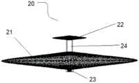
图1为本发明一实施例的左心耳封堵器结构示意图,包括密封单元和固定单元;Fig. 1 is a structural schematic diagram of a left atrial appendage occluder according to an embodiment of the present invention, including a sealing unit and a fixing unit;
图2为图1所示的密封单元结构示意图;Fig. 2 is a schematic structural diagram of the sealing unit shown in Fig. 1;
图3为本发明另一实施例的密封单元结构示意图;Fig. 3 is a schematic structural diagram of a sealing unit according to another embodiment of the present invention;
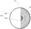
图4至图6a为本发明一实施例的密封单元内部结构示意图;4 to 6a are schematic diagrams of the internal structure of a sealing unit according to an embodiment of the present invention;
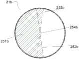
图6b至图6d为本发明其它实施例的密封单元内部密封件结构示意图;Fig. 6b to Fig. 6d are schematic structural diagrams of internal seals of the sealing unit in other embodiments of the present invention;
图7为本发明一实施例的输送装置结构示意图;Fig. 7 is a schematic structural diagram of a conveying device according to an embodiment of the present invention;
图8为图7所述输送装置部分结构示意图;Fig. 8 is a partial structural schematic diagram of the conveying device described in Fig. 7;
图9为本发明另一实施例提供的输送装置的部分结构示意图;Fig. 9 is a partial structural schematic diagram of a delivery device provided by another embodiment of the present invention;
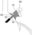
图10为本发明一实施例提供的左心耳封堵器输送系统部分结构示意图;Fig. 10 is a partial structural schematic diagram of the left atrial appendage occluder delivery system provided by an embodiment of the present invention;
图11及图12为图10所述左心耳封堵器输送系统部分结构放大图;Fig. 11 and Fig. 12 are partial structure enlarged views of the delivery system of the left atrial appendage occluder described in Fig. 10;
图13至图16为本发明一实施例的左心耳封堵器输送系统的使用过程示意图。13 to 16 are schematic views of the use process of the left atrial appendage occluder delivery system according to an embodiment of the present invention.
具体实施方式Detailed ways
为更好地理解本发明的技术方案和有益效果,以下结合具体实施例对本发明做详细说明。下述具体实施例仅为部分优选实施例,并非本发明的全部实施例,也并非对本发明的限制。In order to better understand the technical solutions and beneficial effects of the present invention, the present invention will be described in detail below in conjunction with specific examples. The following specific embodiments are only some preferred embodiments, not all embodiments of the present invention, nor limit the present invention.
在介入医疗器械领域,通常定义靠近操作者的一端为“近端”,远离操作者的一端为“远端”。并以此定义任一组件或部件的近端和远端。对于长形组件或可被压缩成长形的组件,“轴向”一般是指植入体和输送装置的长度方向,“径向”一般是指与该“轴向”垂直的方向,并依据此原理定义植入体和输送装置的任一部件的“轴向”和“径向”。In the field of interventional medical devices, the end close to the operator is usually defined as the "proximal end", and the end far away from the operator is defined as the "distal end". And use this to define the proximal and distal ends of any component or part. For elongate components or components that can be compressed into long shape, "axial" generally refers to the length direction of the implant and delivery device, and "radial" generally refers to the direction perpendicular to the "axial", and according to this The principles define "axial" and "radial" for any component of the implant and delivery device.
本发明的技术方案可用于多种封堵装置,例如左心耳封堵器、动脉导管未闭心脏内或血管封堵装置。以下仅以左心耳封堵器为例做具体说明。The technical solution of the present invention can be used in various occlusion devices, such as left atrial appendage occluder, patent ductus arteriosus intracardiac or vascular occlusion device. The following only takes the left atrial appendage occluder as an example for specific description.
如图1所示,本发明一实施例提供的左心耳封堵器100包括密封单元20和固定单元10。密封单元20和固定单元10之间的连接方式为可拆卸连接,也即密封单元20和固定单元10是可以拆卸成独立的个体的。具体地,固定单元20包括固定部11、套管12、收容件13以及锚定件14。本实施例的固定部11具体结构为通过编织丝编织形成的柱形编织体,且在固定部11的近端面和远端面均形成内凹结构,套管12和收容件13均设置在内凹结构内。其中,套管12设置在固定部11近端面上朝向远端凹陷的内凹结构中;收容件13设置在固定部11远端面上朝向近端凹陷的内凹结构中。也就是说,编织丝的近端汇聚于套管12并与套管12相连,编织丝的远端汇聚于收容件13并与收容件13相连。锚定件14便于固定单元10与组织锚定,避免固定单元发生位移。锚定件14可以为锚刺,锚刺突出于固定部11的外表面。As shown in FIG. 1 , a left
套管12包括一过孔,过孔沿左心耳封堵器100的轴向延伸。套管12上还可以设有配合位,从而实现固定单元与输送装置相连,例如套管上可以设有内螺纹或外螺纹,从而与输送装置实现螺纹连接。套管上也可以设置卡槽,从而与输送装置实现卡接。The
密封单元20通过套管12与固定单元10相连。参照图2,密封单元20包括密封部21、限位部22、第一连接件24和第二连接件23。本实施例中,密封部21和限位部22均为由编织丝编织形成的双盘状结构,且二者均呈中间厚边缘薄的碟形(碟型也即越靠近边缘,双盘的两个盘面之间的轴向距离越近)。第一连接件24连接密封部21的远端和限位部22的近端。第一连接件24的外径小于套管12中过孔的内径,且第一连接件24的轴向长度不小于套管12中过孔的轴向长度,从而使得第一连接件14能穿过过孔且套管12不会影响密封部21或限位部22的形状。The
应当理解,密封部和限位部的具体结构本发明不做限制,例如,密封部的盘面可以朝向远端凹陷,或密封部的两个盘面之间还包括腰部等。It should be understood that the specific structure of the sealing part and the limiting part is not limited in the present invention, for example, the disk surface of the sealing part may be concave toward the distal end, or a waist may be included between the two disk surfaces of the sealing part.
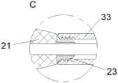
密封部21近端还设有第二连接件23。第二连接件23一方面可以收容密封部21编织丝的端部,另一方面还可以与输送装置相连。例如,第二连接件23上可以设有内螺纹或外螺纹,从而与输送装置实现螺纹连接。第二连接件23上也可以设置卡槽,从而与输送装置实现卡接。The proximal end of the sealing
结合图1和图2,限位部22穿过套管12的过孔后展开,且限位部22的近端靠近套管12的远端。为保证密封单元20与固定单元10的稳定连接,限位部22压缩时的内径应小于套管12上过孔的内径,使得限位部22能穿过过孔;而限位部展开后的最大外轮廓的的尺寸应大于套管12上过孔的内径,使得限位部22不会轻易从套管12中脱出。Referring to FIG. 1 and FIG. 2 , the limiting
可以理解的是,密封部和限位部可以是一体结构。例如可以是一体编织的结构,然后在成型的结构上套一个管材,管材靠近成型结构的远端,再通过热定型等工艺将密封部和限位部定型成盘状结构,并固定套管,使套管不会相对于密封部和限位部发生轴向移动,套管及为第一连接件。It can be understood that the sealing part and the limiting part may be an integral structure. For example, it can be an integrated braided structure, and then a tube is placed on the formed structure, the tube is close to the far end of the formed structure, and then the sealing part and the limiting part are shaped into a disc-shaped structure through heat setting and other processes, and the sleeve is fixed. The sleeve can not move axially relative to the sealing part and the limiting part, and the sleeve is the first connecting part.
可以理解的是,在其它实施例中,密封单元20a的结构也可以如图3所示,限位部22a由管材切割形成,包括多个径向展开的限位杆221a,多个限位杆221a沿第一连接件24a的远端面周向间隔设置。限位杆221a朝向远端延伸后又朝向径向延伸并朝向近端弯折。在受力作用时,多个限位杆221a可以朝向中心靠近,从而使得限位部20a的最大外轮廓尺寸变小。可以理解的是,限位杆也可以不朝向近端弯折,只要限位部展开时的最大外轮廓尺寸大于固定单元近端的套管上的过孔的内径,且限位部压缩后的最大外径小于过孔的内径即可。It can be understood that, in other embodiments, the structure of the
当限位部受到朝向近端的拉力时(例如需要更换密封单元时),限位部的近端与套管的远端相抵靠,套管也将受到朝向近端的拉力,限位部和固定单元的近端面将发生形变。为保证在此过程中限位部先变形收入套管内,从而减小对固定单元的拉力,减弱固定单元的变形趋势,优选限位部的变形能力大于固定单元近端面的变形能力。可以理解为,在相同轴向力或径向力的作用下,限位部的轴向变化量或径向变化量大于固定单元近端面的轴向变化量或径向变化量。例如可以设置限位部的编织丝的丝径小于固定单元近端面的编织丝的丝径。When the limiting part is subjected to a pulling force towards the proximal end (for example, when the sealing unit needs to be replaced), the proximal end of the limiting part abuts against the distal end of the sleeve, and the sleeve will also be subjected to a pulling force towards the proximal end. The limiting part and the The proximal face of the fixation element will deform. In order to ensure that the limiting part is first deformed into the casing during this process, thereby reducing the tension on the fixing unit and weakening the deformation tendency of the fixing unit, the deformation capacity of the limiting part is preferably greater than that of the proximal surface of the fixing unit. It can be understood that, under the same axial force or radial force, the axial variation or radial variation of the limiting portion is greater than the axial variation or radial variation of the proximal end surface of the fixing unit. For example, the wire diameter of the braided wire of the limiting portion may be smaller than the wire diameter of the braided wire of the proximal end surface of the fixing unit.
此外,为方便更换密封单元,使限位部收朝向近端的拉力时更容易收进套管内,套管上过孔的远端开口可设置成喇叭状,也即越靠近远端,过孔的孔径越大。In addition, in order to facilitate the replacement of the sealing unit, it is easier for the stopper to be retracted into the casing when the pulling force toward the proximal end is received. The larger the pore size.
可以理解的是,设置在固定单元远端的收容件、第一连接件和第二连接件均可以为套管结构,即均为中空的管状结构。It can be understood that the receiving part, the first connecting part and the second connecting part arranged at the distal end of the fixing unit may all be sleeve structures, that is, all be hollow tubular structures.
可以理解的是,在其它实施例中,固定单元或密封单元至少一个可以通过管材切割形成。It can be understood that, in other embodiments, at least one of the fixing unit or the sealing unit can be formed by cutting a pipe.
可以理解的是,当密封单元和固定单元均通过编织丝编织而成时,编织丝的端部均汇聚在近端或远端。It can be understood that when both the sealing unit and the fixing unit are braided by braiding wires, the ends of the braiding wires converge at the proximal end or the distal end.
为使导丝可以沿轴向穿过左心耳封堵器,本实施例的左心耳封堵器还具有轴向通道。本实施例的固定单元10与密封单元20同轴设置,并且固定单元10与密封单元20均设有可供导丝通过的通孔。具体地,密封单元20上的第一连接件24、第二连接件23,以及固定单元的套管12、收容件13同轴且均设有通孔或过孔。此外,密封单元20还包括密封件25,密封件25中心部分存在可供导丝通过的间隙。因此,固定单元10和密封单元20上的通道以及密封件25上的间隙以及三者之间的空间共同构建了供导丝穿过的轴向通道。In order to allow the guide wire to pass through the left atrial appendage occluder in the axial direction, the left atrial appendage occluder in this embodiment also has an axial channel. In this embodiment, the fixing
具体地,密封件25设在密封部21的双盘结构的两个盘面26之间。如图4至图6a所示,密封件25包括至少两个薄膜体251。薄膜体251包括至少一个固定边252和至少一个自由边253。薄膜体251通过固定边252与密封部21相连。自由边253相对密封部21自由,也即二者之间至少部分无相对束缚。以垂直于左心耳封堵器轴向的横截面为投影面,任一薄膜体251在该投影面上的投影面积小于密封部21的盘面26在该投影面上的投影面积,但密封件25在该投影面上的投影面积大致与密封部21的盘面26在该投影面上的投影面积相等,也即密封件25能保证密封部21的封堵效果。本实施例的密封件25包括3个薄膜体251,且薄膜体251均包括一个固定边252和一个自由边253。其中,固定边252为圆弧,且基本等于与盘面26周长的一半;自由边253为直线型,长度基本与盘面26的直径相等。因此,每个薄膜体251的自由边253均通过盘面26的中心,且任意两个薄膜体251均存在交叠的部分。任意两个薄膜体251的自由边253存在交点254,多个自由边253之间构成可供导丝通过的间隙,尤其是当密封单元被压缩后,薄膜体的自由边拱起形成供导丝通过的间隙,当密封单元展开后,自由边附近也可以容纳导丝。本实施例中,多个交点254在盘面26的中心重合,且基本位于左心耳封堵器100的中心轴线上。Specifically, the sealing
应当理解,本发明对薄膜体的具体形状不做限制,在其它实施例中,薄膜体也可以采用其它形状。例如,薄膜体可以是扇形结构,扇形结构包括两个直边和一个圆弧边,且扇形直边的长度与盘面的半径相等。圆弧边和其中一个直边均为固定边,另一个直边为自由边。也即扇形结构中的一个直边至少部分未与密封部相连,而扇形结构的另一个直边以及圆弧边与密封部相连。进一步地,当薄膜体均为扇形结构时,相邻两个扇形结构中的固定边相互远离,也即其中一个扇形结构上与密封部相连的直边远离相邻任一个扇形结构上与密封部相连的直边;或者,相邻两个薄膜体中,其中一个扇形结构上与密封部相连的直边靠近另一扇形结构上与密封部相连的直边。此时,为保证导丝能从密封件中心穿过,扇形结构的顶角处可以不与密封部相连。It should be understood that the present invention does not limit the specific shape of the film body, and in other embodiments, the film body may also adopt other shapes. For example, the film body may be a fan-shaped structure, the fan-shaped structure includes two straight sides and one arc side, and the length of the fan-shaped straight side is equal to the radius of the disk surface. The arc edge and one of the straight edges are fixed edges, and the other straight edge is a free edge. That is, one straight side of the fan-shaped structure is at least partially not connected to the sealing portion, while the other straight side and the arc side of the fan-shaped structure are connected to the sealing portion. Further, when the film bodies are all fan-shaped structures, the fixed sides in two adjacent fan-shaped structures are far away from each other, that is, the straight edge connected to the sealing part on one of the fan-shaped structures is far away from the sealing part on any adjacent fan-shaped structure. or, in two adjacent film bodies, the straight side connected to the sealing part on one fan-shaped structure is close to the straight side connected to the sealing part on the other fan-shaped structure. At this time, in order to ensure that the guide wire can pass through the center of the sealing member, the corners of the fan-shaped structure may not be connected with the sealing part.
可以理解的是,相邻薄膜体之间的自由边可以相邻设置,也可以一个薄膜体的自由边与另一薄膜体的固定边相邻设置。优选地,一个薄膜体与另一薄膜体之间至少部分覆盖,且相互覆盖的部分包括至少一个自由边,使得密封部受到的压力可以从覆盖部分的自由边处释放。从而,随心脏跳动,密封部自由边部分张开,得以释放压力,同时,薄膜体之间存在重叠的覆盖部分,血栓并不会从自由边附近进入心室腔内。应当理解,当相邻的两个薄膜体之间紧邻但不覆盖时,密封单元采用双盘结构,两个盘面一定程度也可以限制自由边过分张开,从而依旧可以阻拦血栓通过。It can be understood that the free sides between adjacent film bodies can be arranged adjacently, or the free side of one film body can be arranged adjacent to the fixed side of another film body. Preferably, one film body is at least partially covered by another film body, and the mutually covered parts include at least one free edge, so that the pressure on the sealing part can be released from the free edge of the covered part. Therefore, as the heart beats, the free side of the sealing part opens to release the pressure. At the same time, there are overlapped covering parts between the membranes, so thrombus will not enter the ventricle cavity from near the free side. It should be understood that when two adjacent film bodies are adjacent to each other but not covered, the sealing unit adopts a double disc structure, and the two disc surfaces can also limit the excessive expansion of the free edges to a certain extent, so as to still block the passage of thrombus.
在其它实施例中,密封件21a的结构也可以如图6b和图6c所示。至少一个薄膜体251的自由边252a包括两个缺口255a,且两个缺口靠近密封件21a的中心,在两个缺口255a之间形成一个凸边256a,凸边256a可以跨过另一薄膜体的自由边,使得另一薄膜体的自由边卡如缺口255a中,如图6c所示。这样,在完成封堵器植入以及后续操作后,将导丝撤出时,可以利用导丝使凸边256a跨过另一薄膜体的自由边,避免两个薄膜体的自由边之间因心脏内血压变化而形成较大的开口,起到锁定自由边的作用。可以理解的是,在其它实施例中,也可以不设置缺口。In other embodiments, the structure of the sealing
在其它实施例中,密封件21b的结构也可以如图6c所示。缝合薄膜体时,其中一个薄膜体251b的自由边252b跨过另一薄膜体的自由边。也即薄膜体251b的一部分自由边252b位于相邻一个薄膜体的下方,另一部分自由边252b跨过该相邻的薄膜体,位于该相邻的薄膜体的上方,从而在密封件21b靠近中心的地方形成供导丝通过的交点254b。这样,也可以加强薄膜体之间的密封作用,避免两个薄膜体的自由边之间因心脏内血压变化而形成较大的开口,起到锁定自由边的作用。In other embodiments, the structure of the sealing
在左心耳封堵器上设置可供导丝通过的通道,主要是为了方便密封单元更换。此外,当左心耳封堵器植入后,如果需要进行后续操作,如消融操作,则可以方便地将消融装置沿着导丝伸入到左心耳内。此外,左心耳封堵器完全释放后,可以将导丝保留于体内,若观察后需要更换固定单元,则可以再次通过导丝送入输送装置,将封堵器收回,并进行替换。如若没有导丝,需要用活检钳进入体内将封堵器取出,这种方式对组织伤害较大。A channel through which the guide wire can pass is provided on the left atrial appendage occluder mainly for the convenience of replacing the sealing unit. In addition, after the LAA occluder is implanted, if subsequent operations, such as ablation operations, are required, the ablation device can be conveniently inserted into the LAA along the guide wire. In addition, after the left atrial appendage occluder is completely released, the guide wire can be kept in the body. If the fixing unit needs to be replaced after observation, the guide wire can be sent into the delivery device again, and the occluder can be retracted and replaced. If there is no guide wire, it is necessary to use biopsy forceps to enter the body to remove the occluder, which will cause greater damage to the tissue.
可以理解的是,对于不需要导丝辅助植入时,左心耳封堵器可以不设置相应的供导丝通过的通道。此时,密封单元和固定单元上可以不设置相应通孔。而密封体中心也无需存在间隙,例如,多个薄膜体的自由边可以平行设置,且相邻两个薄膜体之间存在相互覆盖的部分;或者薄膜体的形状和面积均与密封部的盘面在垂直于上述投影面的投影面相等,但薄膜体的固定边小于盘面的周长,也即薄膜体的边缘未全部与密封部相连;或者密封件包括一个环形薄膜体和一个圆形薄膜体,圆形薄膜体的直径稍大于环形薄膜体的内径,且圆形薄膜体的边缘与密封部相连,环形薄膜体的内环边为自由边,环形薄膜体的外环边为固定边,且环形薄膜体部分覆盖圆形薄膜体。因此,只要保证薄膜体存在自由边以释放应力,同时密封件的投影面积与密封部的投影面积大致相等以保证密封件能封堵血栓即可。It can be understood that, when a guide wire is not required for assisted implantation, the left atrial appendage occluder may not be provided with a corresponding channel for the guide wire to pass through. At this time, corresponding through holes may not be provided on the sealing unit and the fixing unit. And there is no need for a gap in the center of the sealing body. For example, the free edges of a plurality of thin film bodies can be arranged in parallel, and there is a mutual covering part between two adjacent thin film bodies; The projection plane perpendicular to the above-mentioned projection plane is equal, but the fixed side of the film body is smaller than the perimeter of the disk surface, that is, the edges of the film body are not all connected to the sealing part; or the sealing member includes an annular film body and a circular film body , the diameter of the circular film body is slightly larger than the inner diameter of the annular film body, and the edge of the circular film body is connected to the sealing part, the inner ring edge of the annular film body is a free edge, and the outer ring edge of the annular film body is a fixed edge, and The annular membrane body partially covers the circular membrane body. Therefore, it only needs to ensure that there are free edges in the film body to release the stress, and at the same time, the projected area of the sealing member is approximately equal to the projected area of the sealing part to ensure that the sealing member can block the thrombus.
可以理解的是,在其它实施例中,薄膜体可以采用弹性材料,例如编织布或硅胶等,从而可以更好地适应心脏内的血压变化,此时,无需在薄膜体上设置自由边。此外,因硅胶具有一定粘性,当需要通导丝时,硅胶的自由边允许导丝通过,当导丝撤出后,硅胶的自由边又会与另一片硅胶粘在一起,从而提供良好的阻挡血栓的作用。It can be understood that, in other embodiments, the membrane body can be made of elastic materials, such as woven cloth or silicone, so as to better adapt to changes in blood pressure in the heart. At this time, no free edge is required on the membrane body. In addition, because the silicone has a certain viscosity, when the guidewire needs to be passed, the free side of the silicone allows the guidewire to pass through, and when the guidewire is withdrawn, the free side of the silicone will stick to another piece of silicone to provide a good barrier Thrombosis.
应当理解,对于无需考虑薄膜体受应力发生破损的情况时,薄膜体可以不设置自由边,即薄膜体的边完全固定在密封部上。It should be understood that when it is not necessary to consider that the film body is damaged due to stress, the film body may not be provided with free edges, that is, the edges of the film body are completely fixed on the sealing portion.
应当理解,其它一体成型的封堵装置也可以采用本发明的多个薄膜体的设计方案,也就是说,在其它实施例中,密封单元和固定单元也可以是一体结构,例如,密封单元和固定单元可以由同一根中控管材切割形成;或者在其它实施例中,固定单元或密封单元中至少一个是通过编织丝编织形成,并且编织丝的端部收容于套管内,套管内进一步设置可供导丝穿过的通孔;或者在其它实施例中,固定单元或密封单元中至少一个是通过管材切割形成的结构。此外,密封单元与固定单元可以直接通过第一连接件固定相连,即密封单元不包括限位部。It should be understood that other integrally formed blocking devices can also adopt the design of multiple membrane bodies of the present invention, that is to say, in other embodiments, the sealing unit and the fixing unit can also be an integral structure, for example, the sealing unit and The fixing unit can be formed by cutting the same central control pipe; or in other embodiments, at least one of the fixing unit or the sealing unit is formed by weaving braided wire, and the end of the braided wire is accommodated in the sleeve, and the sleeve is further provided with a A through hole for the guide wire to pass through; or in other embodiments, at least one of the fixing unit or the sealing unit is a structure formed by cutting a pipe. In addition, the sealing unit and the fixing unit may be fixedly connected directly through the first connecting member, that is, the sealing unit does not include a limiting portion.
本发明还提供了一左心耳封堵器输送系统,该输送系统包括上述任一左心耳封堵器和输送装置200。如图7所述,输送装置200主要包括控制组件40和导管组件30。控制组件40设于导管组件30的近端,并用于控制导管组件30的移动,从而实现对左心耳封堵器的植入、释放或回收。控制组件40的实现方式众多,本发明不做详述。The present invention also provides a left atrial appendage occluder delivery system, which includes any left atrial appendage occluder and
如图8所示,导管组件30包括同轴设置的外鞘管31、第一连接导管32和第二连接导管33。其中,第一连接导管32套设在第二连接导管33的外周,外鞘管31套设在第一连接导管32的外周,且三者均可以两两相互移动。外鞘管31、第一连接导管32和第二连接导管33均为中空管体,且本实施例中第二连接导管33的内腔还可供导丝34穿过,以始终保持导丝路径。外鞘管31可以将左心耳封堵器的固定单元完全收容其中,当外鞘管31朝向近端移动时,可以逐渐撤除对固定单元的束缚,从而使得固定单元展开。第一连接导管32与固定单元近端的套管相连,并带动固定单元轴向移动,同时保证释放过程中固定单元位置稳定不产生晃动。同时,第一连接导管32还能起到束缚密封单元的作用,即第一连接导管32固定单元解除连接关系并朝向近端移动时,可以撤除对密封单元的径向束缚,使得密封单元可以径向展开。第二连接导管33与密封单元的近端连接,可带动密封单元轴向移动。本实施例的第一连接导管32及第二连接导管33均采用螺纹连接的方式与左心耳封堵器相连,即第一连接导管32远端部和第二连接导管33的远端部均设有内螺纹,从而与固定单元近端的套管上的外螺纹以及第二连接件上的外螺纹进行螺纹连接。As shown in FIG. 8 , the
可以理解的是,在其它实施例中,也可以在第一连接导管和第二连接导管的远端部分别设置外螺纹,在套管和第二连接件上设置相应的内螺纹,本发明并不对内外螺纹的设置进行限制。It can be understood that, in other embodiments, external threads can also be provided on the distal ends of the first connecting conduit and the second connecting conduit respectively, and corresponding internal threads can be provided on the sleeve and the second connecting piece. The present invention does not There are no restrictions on the setting of internal and external threads.
同样可以理解的是,在其它实施例中,第一连接导管与固定单元、第二连接导管与密封单元之间也可以通过其它方式连接,例如可以采用卡接的方式相连,只要能保证输送装置能与左心耳封堵器可拆卸相连即可。It can also be understood that in other embodiments, the first connecting conduit and the fixing unit, the second connecting conduit and the sealing unit can also be connected in other ways, for example, they can be connected in a clamping manner, as long as the delivery device can be guaranteed It only needs to be detachably connected with the left atrial appendage occluder.
在其它实施例中,如图9所示,导管组件30还可以包括内鞘管35。内鞘管35与第二连接导管33同轴设置,且内鞘管35设于第一连接导管32和第二连接导管33之间。此时,内鞘管35起到束缚密封单元的作用,当第一连接导管32与固定单元的连接解除并朝向近端移动时,密封单元并不会因此展开,这样,密封单元不直接与第一连接导管32的内壁相接触,也就不会对第一连接导管32轴向移动产生摩擦阻力。并且,当密封单元尺寸不合适,需要更换时,可以通过朝向远端移动内鞘管35,并朝向近端移动第二连接导管33,将密封单元收入内鞘管35内,再朝向远端移动第一连接导管32,使第一连接导管32再次与固定单元连接,保证固定单元的位置稳定之后,再更换尺寸合适的密封单元。In other embodiments, as shown in FIG. 9 , the
如图10至图12所示,当左心耳封堵器与输送装置相连且外鞘管31后撤使固定部11展开时,限位部22也处于展开状态,实现固定单元10与密封单元20相连,且限位部22阻挡密封单元20从套管12内脱落。此时,第一连接件24正好位于套管22的过孔内。第一连接导管32仍与固定单元10的套管保持相连状态,密封部21受到第一连接导管32的束缚。第二连接导管33与第二连接件23相连,并且,对第二连接导管33施加朝向近端的拉力时,也可以使密封部21处于收束状态。As shown in Figures 10 to 12, when the left atrial appendage occluder is connected to the delivery device and the
图13至图16示出了本发明的左心耳封堵器输送系统的使用过程示意图。将左心耳封堵器植入到左心耳50内部前,根据导丝34建立的路径,首先将输送装置沿着导丝进入体内,使外鞘管31的远端伸入左心耳50的开口;然后后撤外鞘管31,使固定单元10展开并锚定在左心耳50的内壁上,此时,密封单元20的限位部也紧随固定单元10展开;接着进一步回撤外鞘管31,露出第一连接导管32的远端,进一步转动第一连接导管32,使第一连接导管32与固定单元10的连接解脱;再接着朝向近端回撤第一连连接导管32,并同时朝向远端推送第二连接导管33,使密封单元20的密封部展开,封堵在左心耳50的口部。接着再通过输送装置注射造影剂,观察封堵效果。如若封堵良好,则转动第二连接导管33,解除第二连接导管33与密封单元20近端的连接,撤出输送装置,完成左心耳封堵器的植入。若密封单元的封堵效果不佳,需要更换其它尺寸的密封单元,则朝向近端后撤第二连接导管33,同时朝向远端推动第一连接导管32,使限位部朝向近端移动穿过套管,从而密封单元完全被收束到第一连接导管32内,同时转动第二连接导管32使其与固定单元的套管再次相连;然后沿着导丝34将密封单元撤出,更换尺寸合适的密封单元,再一次按照上述步骤完成密封单元的植入。Fig. 13 to Fig. 16 show the schematic diagrams of the use process of the left atrial appendage occluder delivery system of the present invention. Before implanting the left atrial appendage occluder inside the left
可以理解的是,在其它实施例中,输送系统也可以借助输送鞘进入体内,此时,不再需要导丝作为路径指引。It can be understood that, in other embodiments, the delivery system can also enter the body through a delivery sheath, and at this time, a guide wire is no longer needed as a path guide.
综上所述,本发明的左心耳封堵器以及左心耳封堵器输送系统可以率先使固定单元释放,当密封单元展开后,如若尺寸不合适,可以方便快速地将密封单元撤出,替换尺寸合适的密封单元。无需将整个左心耳封堵器取出,简化替换过程。To sum up, the LAA occluder and the delivery system for the LAA occluder of the present invention can release the fixing unit first, and when the sealing unit is deployed, if the size is not suitable, the sealing unit can be withdrawn conveniently and quickly for replacement. Properly sized sealed unit. There is no need to take out the entire left atrial appendage occluder, which simplifies the replacement process.
应当理解,上述实施例仅为优选实施例,本领域技术人员可以根据实际需求对部分结构做简单替换或变换。本发明的保护范围以权利要求为准。It should be understood that the above-mentioned embodiments are only preferred embodiments, and those skilled in the art may simply replace or transform some structures according to actual needs. The protection scope of the present invention shall be determined by the claims.
Claims (8)
Priority Applications (1)
| Application Number | Priority Date | Filing Date | Title |
|---|---|---|---|
| CN201911404922.8ACN113116407B (en) | 2019-12-31 | 2019-12-31 | Plugging device |
Applications Claiming Priority (1)
| Application Number | Priority Date | Filing Date | Title |
|---|---|---|---|
| CN201911404922.8ACN113116407B (en) | 2019-12-31 | 2019-12-31 | Plugging device |
Publications (2)
| Publication Number | Publication Date |
|---|---|
| CN113116407A CN113116407A (en) | 2021-07-16 |
| CN113116407Btrue CN113116407B (en) | 2023-05-02 |
Family
ID=76768584
Family Applications (1)
| Application Number | Title | Priority Date | Filing Date |
|---|---|---|---|
| CN201911404922.8AActiveCN113116407B (en) | 2019-12-31 | 2019-12-31 | Plugging device |
Country Status (1)
| Country | Link |
|---|---|
| CN (1) | CN113116407B (en) |
Families Citing this family (3)
| Publication number | Priority date | Publication date | Assignee | Title |
|---|---|---|---|---|
| CN114376644B (en)* | 2021-12-07 | 2025-09-30 | 杭州堃博生物科技有限公司 | One-way valve device for use in the airway |
| WO2024046392A1 (en)* | 2022-08-30 | 2024-03-07 | 先健科技(深圳)有限公司 | Occlusion apparatus |
| CN116570338B (en)* | 2023-07-13 | 2023-10-10 | 北京航空航天大学 | Left auricle occluder and placement method |
Family Cites Families (4)
| Publication number | Priority date | Publication date | Assignee | Title |
|---|---|---|---|---|
| CN104688292B (en)* | 2015-02-15 | 2017-08-25 | 上海形状记忆合金材料有限公司 | A kind of left atrial appendage occlusion device and plugging system |
| CN109567891A (en)* | 2017-09-29 | 2019-04-05 | 上海微创医疗器械(集团)有限公司 | Occluder for left auricle and left atrial appendage occlusion device |
| CN108354638B (en)* | 2018-03-30 | 2024-06-18 | 天津瑞奇外科器械股份有限公司 | Sealing assembly for puncture sleeve, puncture sleeve and puncture device |
| CN108784806B (en)* | 2018-08-21 | 2023-08-11 | 联合微创医疗器械(深圳)有限公司 | Sealing assembly and puncture outfit |
- 2019
- 2019-12-31CNCN201911404922.8Apatent/CN113116407B/enactiveActive
Also Published As
| Publication number | Publication date |
|---|---|
| CN113116407A (en) | 2021-07-16 |
Similar Documents
| Publication | Publication Date | Title |
|---|---|---|
| CN102805654B (en) | Occluder for left auricle | |
| US8114123B2 (en) | Apparatus and methods for tissue gathering and securing | |
| ES2588687T3 (en) | FOP occluder screw retention mechanism | |
| JP5744893B2 (en) | Systems that provide access and closure to the organization | |
| JP2015501691A (en) | Medical occlusion device | |
| CN113116407B (en) | Plugging device | |
| CN104688292B (en) | A kind of left atrial appendage occlusion device and plugging system | |
| CN104274224B (en) | Left atrial appendage occlusion device | |
| ES2661459T3 (en) | Devices to occlude or promote fluid flow | |
| CN204133530U (en) | Occluder for left auricle | |
| US7691115B2 (en) | Occlusion device with flexible fabric connector | |
| US20050177182A1 (en) | System and method for delivering a left atrial appendage containment device | |
| CN204683686U (en) | A kind of left atrial appendage occlusion device and plugging system | |
| US20050203568A1 (en) | Filter mesh for preventing passage of embolic material form an atrial appendage | |
| WO2016000661A1 (en) | Occluder and occlusion device | |
| JP2008514291A (en) | Double fixing system for delivery / recovery of occluder devices | |
| CN108135594B (en) | Vascular closure device | |
| CN101933839A (en) | Connecting device for interventional medical equipment and method of use thereof | |
| CN114469212B (en) | Limiting device and stitching device | |
| KR20240008951A (en) | Apparatus and method for sealing a vascular puncture | |
| CN117357188B (en) | Tissue ligation system and use method thereof | |
| CN113116409B (en) | Plugging device and plugging device conveying system | |
| CN203576563U (en) | Plugging device with locking mechanism | |
| CN114073560A (en) | Blocking device | |
| CN109247965B (en) | Suturing device |
Legal Events
| Date | Code | Title | Description |
|---|---|---|---|
| PB01 | Publication | ||
| PB01 | Publication | ||
| SE01 | Entry into force of request for substantive examination | ||
| SE01 | Entry into force of request for substantive examination | ||
| GR01 | Patent grant | ||
| GR01 | Patent grant |