CN113110453B - Artificial potential field obstacle avoidance method based on graph transformation - Google Patents
Artificial potential field obstacle avoidance method based on graph transformationDownload PDFInfo
- Publication number
- CN113110453B CN113110453BCN202110405392.XACN202110405392ACN113110453BCN 113110453 BCN113110453 BCN 113110453BCN 202110405392 ACN202110405392 ACN 202110405392ACN 113110453 BCN113110453 BCN 113110453B
- Authority
- CN
- China
- Prior art keywords
- potential field
- plane map
- obstacle
- target point
- point
- Prior art date
- Legal status (The legal status is an assumption and is not a legal conclusion. Google has not performed a legal analysis and makes no representation as to the accuracy of the status listed.)
- Active
Links
- 238000000034methodMethods0.000titleclaimsabstractdescription57
- 230000009466transformationEffects0.000titleclaimsabstractdescription15
- 238000013507mappingMethods0.000claimsabstractdescription39
- 108010046685Rho FactorProteins0.000claimsdescription4
- 238000010586diagramMethods0.000description11
- 238000010276constructionMethods0.000description3
- 238000005381potential energyMethods0.000description2
- 230000009286beneficial effectEffects0.000description1
- 230000007547defectEffects0.000description1
- 238000009795derivationMethods0.000description1
- 230000000694effectsEffects0.000description1
- 238000004088simulationMethods0.000description1
Images


Classifications
- G—PHYSICS
- G05—CONTROLLING; REGULATING
- G05D—SYSTEMS FOR CONTROLLING OR REGULATING NON-ELECTRIC VARIABLES
- G05D1/00—Control of position, course, altitude or attitude of land, water, air or space vehicles, e.g. using automatic pilots
- G05D1/02—Control of position or course in two dimensions
- G05D1/021—Control of position or course in two dimensions specially adapted to land vehicles
- G05D1/0231—Control of position or course in two dimensions specially adapted to land vehicles using optical position detecting means
- G05D1/0246—Control of position or course in two dimensions specially adapted to land vehicles using optical position detecting means using a video camera in combination with image processing means
Landscapes
- Engineering & Computer Science (AREA)
- Physics & Mathematics (AREA)
- Computer Vision & Pattern Recognition (AREA)
- Multimedia (AREA)
- Electromagnetism (AREA)
- Aviation & Aerospace Engineering (AREA)
- Radar, Positioning & Navigation (AREA)
- Remote Sensing (AREA)
- General Physics & Mathematics (AREA)
- Automation & Control Theory (AREA)
- Management, Administration, Business Operations System, And Electronic Commerce (AREA)
Abstract
Description
Translated fromChinese技术领域technical field
本发明涉及路径规划技术领域,具体为一种基于图形变换的人工势场避障方法。The invention relates to the technical field of path planning, in particular to an artificial potential field obstacle avoidance method based on graphic transformation.
背景技术Background technique
人工势场法是一种应用较为广泛的路径规划方法,其基本思想是在空间中构建一个虚拟力场,使运动对象与目标点之间存在引力,同时与障碍物之间存在斥力,运动对象沿着引力和斥力合力的方向运动,从而躲避障碍物,直至抵达目标点。The artificial potential field method is a widely used path planning method. Its basic idea is to build a virtual force field in space, so that there is a gravitational force between the moving object and the target point, and there is a repulsion force between the moving object and the obstacle. Move in the direction of the combined force of attraction and repulsion to avoid obstacles until reaching the target point.
人工势场法存在一些缺陷,如中国发明专利CN110209171A中就存在运动对象在移动过程中易陷入势场局部极小点的问题,此时运动对象受到的合力为0停止移动,导致目标点不可达。因此如何消除合力场中的局部极小值点,是人工势场法能够适应更多复杂应用场景的关键性问题。The artificial potential field method has some defects. For example, in the Chinese invention patent CN110209171A, there is a problem that the moving object is easy to fall into the local minimum point of the potential field during the movement process. At this time, the resultant force received by the moving object is 0 and stops moving, resulting in the unreachable target point. . Therefore, how to eliminate the local minimum points in the resultant force field is the key problem that the artificial potential field method can adapt to more complex application scenarios.
发明内容SUMMARY OF THE INVENTION
本发明的目的是:针对现有技术中人工势场法构造的合力场中存在局部极小值点,引发局部最优解使目标点不可达的问题,提出一种基于图形变换的人工势场避障方法。The purpose of the present invention is: in view of the existence of local minimum points in the resultant force field constructed by the artificial potential field method in the prior art, causing the problem that the local optimal solution makes the target point unreachable, an artificial potential field based on graph transformation is proposed. Obstacle avoidance method.
本发明为了解决上述技术问题采取的技术方案是:The technical scheme that the present invention takes in order to solve the above-mentioned technical problems is:
一种基于图形变换的人工势场避障方法,包括以下步骤:An artificial potential field obstacle avoidance method based on graphic transformation, comprising the following steps:
步骤一:获取包含起点,目标点以及障碍物位置和障碍物形状的平面地图;Step 1: Obtain a flat map containing the starting point, the target point, and the location and shape of the obstacle;
步骤二:将平面地图以目标点为圆心的引力势场等势线展开,并进行坐标映射;Step 2: Expand the equipotential line of the gravitational potential field with the target point as the center of the plane map, and perform coordinate mapping;
步骤三:将坐标映射后的新平面地图中的障碍物进行膨胀操作;Step 3: Inflate the obstacles in the new plane map after coordinate mapping;
步骤四:将膨胀后的新平面地图中非连通的障碍物分别进行提取;Step 4: Extract the non-connected obstacles in the expanded new plane map respectively;
步骤五:将提取到的障碍物分别构建凸包;Step 5: Construct convex hulls of the extracted obstacles respectively;
步骤六:以障碍物的凸包的包络范围,即凸壳,替换坐标映射后的平面地图中的障碍物;Step 6: Replace the obstacles in the plane map after coordinate mapping with the envelope range of the convex hull of the obstacle, that is, the convex hull;
步骤七:将障碍物替换后的平面地图进行逆映射;Step 7: Inversely map the plane map after the obstacles are replaced;
步骤八:将引力函数和斥力函数应用到逆映射后的平面地图中构建合势场;Step 8: Apply the gravitational function and the repulsive force function to the inversely mapped plane map to construct a combined potential field;
步骤九:找到从起点沿合势场梯度下降最快的方向到达目标点的路径,即为期望路径。Step 9: Find the path from the starting point to the target point along the fastest gradient of the combined potential field, which is the desired path.
进一步的,所述坐标映射的映射关系为:Further, the mapping relationship of the coordinate mapping is:


其中xmax为平面地图的高,ymax为平面地图的宽,(x,y)为平面地图中待映射坐标点,I(x,y)为平面地图上点(x,y)的像素值,xg和yg为目标点的横坐标和纵坐标,

进一步的,所述凸包根据Graham法或Jarvis步进法构建。Further, the convex hull is constructed according to the Graham method or the Jarvis stepping method.
进一步的,所述平面地图为400乘400的二值图像。Further, the plane map is a 400-by-400 binary image.
进一步的,所述逆映射的公式为:Further, the formula of the inverse mapping is:


进一步的,所述引力势场函数表示为:Further, the gravitational potential field function is expressed as:

其中katt为引力势场的比例增益因子,m为引力势场因子,1<m≤3,X为待求引力势场的位置坐标,Xg为目标点的位置坐标,ρ(X,Xg)为X和Xg之间的欧氏距离。where katt is the proportional gain factor of the gravitational potential field, m is the gravitational potential field factor, 1<m≤3, X is the position coordinate of the gravitational potential field to be obtained, Xg is the position coordinate of the target point, ρ(X, Xg ) is the Euclidean distance between X and Xg .
进一步的,所述斥力势场函数表示为:Further, the repulsion potential field function is expressed as:

其中krep为斥力势场的比例增益因子,n为斥力势场因子,ρ0为障碍物斥力的最大影响距离,X为待求斥力势场的位置坐标,X0为障碍物的位置坐标,ρ(X,X0)为X和X0之间的欧氏距离,UREP(X)即为X处的受到的斥力大小。where krep is the proportional gain factor of the repulsion potential field, n is the repulsion potential field factor, ρ0 is the maximum influence distance of the obstacle repulsion, X is the position coordinate of the repulsion potential field to be obtained, X0 is the position coordinate of the obstacle, ρ(X, X0 ) is the Euclidean distance between X and X0 , and UREP (X) is the magnitude of the repulsive force at X.
进一步的,所述膨胀的大小为ρ0。Further, the size of the expansion is ρ0 .
进一步的,所述ρ0=20。Further, the ρ0 =20.
进一步的,所述m=2,n=2,katt=0.01,krep=500。Further, the m=2, n=2, katt =0.01, krep =500.
本发明的有益效果是:The beneficial effects of the present invention are:
本发明解决了人工势场法容易产生局部极小值点从而产生局部最优解进而导致目标点不可达的问题,如图10和图11。The present invention solves the problem that the artificial potential field method is prone to generate local minimum points, thereby generating a local optimal solution and thus causing the target point to be unreachable, as shown in FIG. 10 and FIG. 11 .
将形态学中的凸包概念应用到人工势场避障方法的障碍物处理中。这一应用以本发明提出的一种专门设计的坐标映射方法为前提,结合两项创新,从理论层面避免了局部极小值点的产生(图6和图7),使目标点可达,具有独创性。该方法相较于其它解决方法原理更加清晰,实现方式更加简单。The concept of convex hull in morphology is applied to obstacle processing of artificial potential field obstacle avoidance method. This application is based on a specially designed coordinate mapping method proposed by the present invention, combined with two innovations, to avoid the generation of local minimum points from the theoretical level (Figure 6 and Figure 7), making the target point reachable, Be original. Compared with other solutions, this method has a clearer principle and simpler implementation.
附图说明Description of drawings
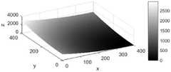
图1为引力场示意图;Figure 1 is a schematic diagram of the gravitational field;
图2为斥力场示意图;Figure 2 is a schematic diagram of the repulsion field;
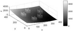
图3为合力场示意图;Figure 3 is a schematic diagram of the resultant force field;
图4为显示障碍物边缘存在局部极小值点示意图;Figure 4 is a schematic diagram showing the existence of a local minimum point at the edge of an obstacle;
图5为显示经本发明方法处理后不存在局部极小值示意图;5 is a schematic diagram showing that there is no local minimum after being processed by the method of the present invention;
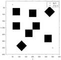
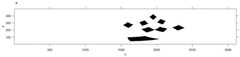
图6为障碍物及目标点地图图像;Figure 6 is a map image of obstacles and target points;
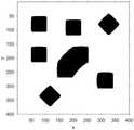
图7为本申请方法处理后的障碍物图像;FIG. 7 is an obstacle image processed by the method of the application;
图8为坐标映射后的图像;Fig. 8 is the image after coordinate mapping;
图9为凸包的构建示意图;Fig. 9 is the construction schematic diagram of convex hull;
图10为本申请方法得到的路径示意图;10 is a schematic diagram of the path obtained by the method of the application;
图11为传统人工势场法得到的路径示意图;Figure 11 is a schematic diagram of the path obtained by the traditional artificial potential field method;
图12为原始平面地图;Figure 12 is the original plane map;
图13为变换后的地图;Figure 13 is the transformed map;
图14为障碍物坐标映射示意图;Figure 14 is a schematic diagram of obstacle coordinate mapping;
图15为凸包的构建示意图;Figure 15 is a schematic diagram of the construction of the convex hull;
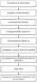
图16为基于图形变换的人工势场避障方法流程图。FIG. 16 is a flow chart of a method for avoiding obstacles in an artificial potential field based on graph transformation.
具体实施方式Detailed ways
需要特别说明的是,在不冲突的情况下,本申请公开的各个实施方式之间可以相互组合。It should be noted that, in the case of no conflict, the various embodiments disclosed in the present application may be combined with each other.
具体实施方式一:参照图16具体说明本实施方式,本实施方式所述的一种基于图形变换的人工势场避障方法,包括以下步骤:Embodiment 1: This embodiment will be described in detail with reference to FIG. 16 . The method for avoiding obstacles in an artificial potential field based on graph transformation described in this embodiment includes the following steps:
步骤一:获取包含起点,目标点以及障碍物位置和障碍物形状的平面地图;Step 1: Obtain a flat map containing the starting point, the target point, and the location and shape of the obstacle;
步骤二:将平面地图以目标点为圆心的引力势场等势线展开,并进行坐标映射;Step 2: Expand the equipotential line of the gravitational potential field with the target point as the center of the plane map, and perform coordinate mapping;
步骤三:将坐标映射后的新平面地图中的障碍物进行膨胀操作;膨胀大小为选取的斥力最大影响范围ρ0,ρ0的值根据在实际应用过程中能够接受的运动对象与障碍物的最小距离确定,一般选取ρ0为能接受的运动对象与障碍物的最小距离的两倍左右;Step 3: Carry out the expansion operation on the obstacles in the new plane map after the coordinate mapping; the expansion size is the maximum influence range of the selected repulsion ρ0 , and the value of ρ0 is based on the acceptable moving objects and obstacles in the actual application process. The minimum distance is determined, and ρ0 is generally selected to be about twice the minimum distance between the acceptable moving object and the obstacle;
步骤四:将膨胀后的新平面地图中非连通的障碍物分别进行提取(可采用Two-Pass法或Seed-Filling种子填充法);Step 4: Extract the non-connected obstacles in the expanded new plane map respectively (Two-Pass method or Seed-Filling seed filling method can be used);
步骤五:将提取到的障碍物分别构建凸包;Step 5: Construct convex hulls of the extracted obstacles respectively;
步骤六:以障碍物的凸包的包络范围,即凸壳,替换坐标映射后的平面地图中的障碍物;Step 6: Replace the obstacles in the plane map after coordinate mapping with the envelope range of the convex hull of the obstacle, that is, the convex hull;
步骤七:将障碍物替换后的平面地图进行逆映射;Step 7: Inversely map the plane map after the obstacles are replaced;
步骤八:将引力函数和斥力函数应用到逆映射后的平面地图中构建合势场;Step 8: Apply the gravitational and repulsive functions to the inversely mapped plane map to construct a combined potential field;
步骤九:找到从起点沿合势场梯度下降最快的方向到达目标点的路径,即为期望路径。Step 9: Find the path from the starting point to the target point along the fastest gradient of the combined potential field, which is the desired path.
在所举示例中,当前梯度下降最快方向通过寻找运动对象所处的位置周围8邻域势场最小值确定,邻域势场最小的方向即为梯度下降最快的方向,找到梯度下降最快方向后,运动对象便向此处转移,依此类推,直到到达目标点。In the given example, the current fastest direction of gradient descent is determined by finding the minimum value of the 8-neighborhood potential field around the position of the moving object, and the direction with the smallest neighborhood potential field is the direction of the fastest gradient descent. After the fast direction, the moving object is transferred here, and so on, until the target point is reached.
构建凸包与坐标映射结合的独特性:Construct the uniqueness of the convex hull combined with the coordinate map:
通过在原始地图中对障碍物构建凸包只能解决人工势场法中部分位置的局部极小值,并不能完全消除局部极小值,只有采取本发明中所述的特定的坐标映射方法,在经过变换后的地图中对障碍物构建凸包,两相结合,才能完全解决人工势场法的局部极小值问题,从而解决运动对象陷入局部最优解导致目标点不可达的问题。By constructing the convex hull of the obstacles in the original map, only the local minima of some positions in the artificial potential field method can be solved, and the local minima cannot be completely eliminated. Only the specific coordinate mapping method described in the present invention is adopted, Constructing a convex hull for the obstacles in the transformed map and combining the two can completely solve the local minimum problem of the artificial potential field method, thereby solving the problem that the moving object falls into the local optimal solution and causes the target point to be unreachable.
具体实施方式二:本实施方式是对具体实施方式一的进一步说明,本实施方式与具体实施方式一的区别是:所述坐标映射的映射关系为:Embodiment 2: This embodiment is a further description of Embodiment 1. The difference between this embodiment and Embodiment 1 is that the mapping relationship of the coordinate mapping is:


其中xmax为平面地图的高,ymax为平面地图的宽,(x,y)为平面地图中待映射坐标点,I(x,y)为平面地图上点(x,y)的像素值(二值化图像中像素点的值,0代表该点无障碍物,大于0代表有障碍物。),xg和yg为目标点的横坐标和纵坐标,

具体实施方式三:本实施方式是对具体实施方式一的进一步说明,本实施方式与具体实施方式一的区别是:所述凸包根据Graham法或Jarvis步进法构建。Embodiment 3: This embodiment is a further description of Embodiment 1. The difference between this embodiment and Embodiment 1 is that the convex hull is constructed according to the Graham method or the Jarvis stepping method.
具体实施方式四:本实施方式是对具体实施方式一的进一步说明,本实施方式与具体实施方式一的区别是:所述平面地图为400乘400的二值图像。Embodiment 4: This embodiment is a further description of Embodiment 1. The difference between this embodiment and Embodiment 1 is that the plane map is a 400×400 binary image.
具体实施方式五:本实施方式是对具体实施方式二的进一步说明,本实施方式与具体实施方式二的区别是:所述逆映射的公式为:Embodiment 5: This embodiment is a further description of the second embodiment. The difference between this embodiment and the second embodiment is that the formula for the inverse mapping is:


具体实施方式六:本实施方式是对具体实施方式一的进一步说明,本实施方式与具体实施方式一的区别是:所述引力势场函数表示为:Embodiment 6: This embodiment is a further description of Embodiment 1. The difference between this embodiment and Embodiment 1 is that the gravitational potential field function is expressed as:

其中katt为引力势场的比例增益因子,m为引力势场因子,1<m≤3,X为待求引力势场的位置坐标,Xg为目标点的位置坐标,ρ(X,Xg)为X和Xg之间的欧氏距离。where katt is the proportional gain factor of the gravitational potential field, m is the gravitational potential field factor, 1<m≤3, X is the position coordinate of the gravitational potential field to be obtained, Xg is the position coordinate of the target point, ρ(X, Xg ) is the Euclidean distance between X and Xg .
具体实施方式七:本实施方式是对具体实施方式一的进一步说明,本实施方式与具体实施方式一的区别是:所述斥力势场函数表示为:Embodiment 7: This embodiment is a further description of Embodiment 1. The difference between this embodiment and Embodiment 1 is that the repulsion potential field function is expressed as:

其中krep为斥力势场的比例增益因子,n为斥力势场因子,ρ0为障碍物斥力的最大影响距离,X为待求斥力势场的位置坐标,X0为障碍物的位置坐标,ρ(X,X0)为X和X0之间的欧氏距离,UREP(X)即为X处的受到的斥力大小。where krep is the proportional gain factor of the repulsion potential field, n is the repulsion potential field factor, ρ0 is the maximum influence distance of the obstacle repulsion, X is the position coordinate of the repulsion potential field to be obtained, X0 is the position coordinate of the obstacle, ρ(X, X0 ) is the Euclidean distance between X and X0 , and UREP (X) is the magnitude of the repulsive force at X.
具体实施方式八:本实施方式是对具体实施方式七的进一步说明,本实施方式与具体实施方式七的区别是:所述膨胀的大小为ρ0。Embodiment 8: This embodiment is a further description of Embodiment 7. The difference between this embodiment and Embodiment 7 is that the size of the expansion is ρ0 .
具体实施方式九:本实施方式是对具体实施方式七的进一步说明,本实施方式与具体实施方式七的区别是:所述ρ0=20。Embodiment 9: This embodiment is a further description of Embodiment 7. The difference between this embodiment and Embodiment 7 is that ρ0 =20.
具体实施方式十:本实施方式是对具体实施方式七的进一步说明,本实施方式与具体实施方式七的区别是:所述m=2,n=2,katt=0.01,krep=500。Embodiment 10: This embodiment is a further description of Embodiment 7. The difference between this embodiment and Embodiment 7 is that m=2, n=2, katt =0.01, and krep =500.
实施例:Example:
步骤一:获取包含起点,目标点以及障碍物位置和形状的平面地图如图12,该图像是大小为400乘400的二值图像。Step 1: Obtain a flat map including the starting point, the target point, and the position and shape of the obstacle, as shown in Figure 12. The image is a binary image with a size of 400 by 400.
步骤二:将图像按以目标点为圆心的引力势场等势线展开,坐标映射公式为式(4)、(5),结果为图14。Step 2: Expand the image according to the equipotential lines of the gravitational potential field with the target point as the center of the circle. The coordinate mapping formulas are equations (4) and (5), and the result is shown in Figure 14.
步骤三:将坐标映射后得到的新地图中障碍物图形进行膨胀操作,膨胀大小为选取的斥力最大影响范围ρ0=20。Step 3: Expansion operation is performed on the obstacle graphics in the new map obtained after the coordinate mapping, and the expansion size is the maximum influence range of the selected repulsion force ρ0 =20.
步骤四:将非连通的障碍物分别提取出来。Step 4: Extract the disconnected obstacles separately.
步骤五:对步骤四中提取的障碍物分别构建凸包,采用的方法为Graham法。Step 5: Construct convex hulls for the obstacles extracted in Step 4, using the Graham method.
步骤六:以障碍物的凸包的包络范围代替原有障碍物,结果为图15。Step 6: Replace the original obstacle with the envelope range of the convex hull of the obstacle, and the result is shown in Figure 15.
步骤七:作步骤二中提到的映射方法的逆映射,将替换后的障碍物重新映射回原来的地图中,逆映射公式为式(6)、(7),结果为图13。Step 7: Do the inverse mapping of the mapping method mentioned in Step 2, and remap the replaced obstacles back to the original map.
步骤八:利用人工势场法的引力函数和斥力函数构建合势场,势场函数为式(1)、(2),其中ρ0=20,m=2,n=2,katt=0.01,krep=500。Step 8: Construct a combined potential field using the gravitational and repulsive functions of the artificial potential field method. The potential field functions are equations (1) and (2), where ρ0 =20, m=2, n=2, katt =0.01 , krep = 500.
步骤九:找到从起点沿合势场梯度下降最快的方向到达目标点的路径,即为期望路径,方式为寻找当前位置8邻域内的势能最小值,将其作为下一路径点,结果为图10。Step 9: Find the path from the starting point to the target point along the fastest gradient of the combined potential field, which is the desired path. The method is to find the minimum potential energy in the neighborhood of the current position 8, and use it as the next path point. The result is Figure 10.
人工势场的引力势场函数构造形式一般为The structural form of the gravitational potential field function of the artificial potential field is generally as follows

其中katt为引力势场的比例增益因子,m为引力势场因子,X为空间中某个位置,Xg为目标点的位置,ρ(X,Xg)为X和Xg之间的欧氏距离,UATT(X)即为X处的受到的引力大小。where katt is the proportional gain factor of the gravitational potential field, m is the gravitational potential field factor, X is a certain position in space, Xg is the position of the target point, ρ(X, Xg ) is the difference between X and Xg Euclidean distance, UATT (X) is the magnitude of the gravitational force at X.
斥力势场函数构造形式一般为The structural form of the repulsive potential field function is generally as follows

其中krep为斥力势场的比例增益因子,n为斥力势场因子,ρ0为障碍物斥力的最大影响距离,X为空间中某个位置,X0为障碍物的位置,ρ(X,X0)为X和X0之间的欧氏距离,UREP(X)即为X处的受到的斥力大小。引力场、斥力场、合力场示意图如图1、图2和图3所示。where krep is the proportional gain factor of the repulsion potential field, n is the repulsion potential field factor, ρ0 is the maximum influence distance of the obstacle repulsion, X is a certain position in space, X0 is the position of the obstacle, ρ(X, X0 ) is the Euclidean distance between X and X0 , and UREP (X) is the magnitude of the repulsive force at X. The schematic diagrams of the gravitational field, the repulsive force field and the resultant force field are shown in Figure 1, Figure 2 and Figure 3.
本发明需要的一些理论依据、部分推导过程:Some theoretical basis and partial derivation process required by the present invention:
1、沿等势线圆周展开的坐标映射与逆映射1. Coordinate mapping and inverse mapping along the circumference of the equipotential line
由图4很容易知道,引力势场的等势线是以目标点为圆心的一系列圆周(弧),如果障碍物的某条处在高势能侧的边从某条等势线外侧穿越到内侧再穿越回外侧,就会在边缘处产生势能的局部极小值点。此时在这一坐标系下补齐障碍物的凹陷并不能解决这一问题,需要首先对图形进行映射处理,将等势线拉直,这样原本障碍物中可能存在局部极小值点的边就会内凹。对映射后的障碍物进行相应处理,填补掉凹陷部分,即可真正消除所有可能产生局部极小值点的位置。具体的映射方式如下。It is easy to know from Figure 4 that the equipotential line of the gravitational potential field is a series of circles (arcs) with the target point as the center. If the inner side crosses back to the outer side, a local minimum point of potential energy will be generated at the edge. At this time, filling the depression of the obstacle in this coordinate system cannot solve this problem. It is necessary to first map the graph and straighten the equipotential lines, so that there may be edges of local minimum points in the original obstacles. will be concave. The mapped obstacles are processed accordingly, and the concave parts are filled, and all the positions that may generate local minimum points can be truly eliminated. The specific mapping method is as follows.
将地图视作一幅图像,如图6,首先根据得到的目标点坐标(Xg,yg),并找到图像上距目标点最远的点与目标点之间的距离Rmax,于是可以知道映射后图像的高为Rmax,宽为2πRmax。设原始图像上某点(x,y)的值为I(x,y),映射后图像与(x,y)对应的点为


其中xmax为原始图像的高,ymax为原始图像的宽,where xmax is the height of the original image, ymax is the width of the original image,


容易得到其逆映射关系为It is easy to obtain its inverse mapping relationship as


根据此映射关系即可以计算出映射后的图像,如图8。According to this mapping relationship, the mapped image can be calculated, as shown in Figure 8.
2、建立障碍物的凸包2. Establish the convex hull of the obstacle
凸包是一个图形学上的概念。对于坐标映射后得到的障碍物地图,将其视为一幅图像时可以将障碍物等同于一系列离散的像素点构成的点集D,则每一个与其它障碍物非连通的障碍物的点集可记为Di,且Di∈D,
需要注意的是,具体实施方式仅仅是对本发明技术方案的解释和说明,不能以此限定权利保护范围。凡根据本发明权利要求书和说明书所做的仅仅是局部改变的,仍应落入本发明的保护范围内。It should be noted that the specific embodiments are only explanations and descriptions of the technical solutions of the present invention, and cannot be used to limit the protection scope of the rights. Any changes made according to the claims and description of the present invention are only partial changes, which should still fall within the protection scope of the present invention.
Claims (8)
Translated fromChinese


Priority Applications (1)
| Application Number | Priority Date | Filing Date | Title |
|---|---|---|---|
| CN202110405392.XACN113110453B (en) | 2021-04-15 | 2021-04-15 | Artificial potential field obstacle avoidance method based on graph transformation |
Applications Claiming Priority (1)
| Application Number | Priority Date | Filing Date | Title |
|---|---|---|---|
| CN202110405392.XACN113110453B (en) | 2021-04-15 | 2021-04-15 | Artificial potential field obstacle avoidance method based on graph transformation |
Publications (2)
| Publication Number | Publication Date |
|---|---|
| CN113110453A CN113110453A (en) | 2021-07-13 |
| CN113110453Btrue CN113110453B (en) | 2022-06-21 |
Family
ID=76717414
Family Applications (1)
| Application Number | Title | Priority Date | Filing Date |
|---|---|---|---|
| CN202110405392.XAActiveCN113110453B (en) | 2021-04-15 | 2021-04-15 | Artificial potential field obstacle avoidance method based on graph transformation |
Country Status (1)
| Country | Link |
|---|---|
| CN (1) | CN113110453B (en) |
Families Citing this family (2)
| Publication number | Priority date | Publication date | Assignee | Title |
|---|---|---|---|---|
| CN114384919B (en)* | 2022-01-17 | 2023-06-27 | 北京格睿能源科技有限公司 | Vehicle obstacle avoidance path planning method and system based on large obstacle form information |
| CN116880473B (en)* | 2023-06-30 | 2024-10-25 | 哈尔滨工业大学(威海) | Unmanned ship path planning method and system based on artificial potential field and A-star fusion |
Family Cites Families (9)
| Publication number | Priority date | Publication date | Assignee | Title |
|---|---|---|---|---|
| CN100494900C (en)* | 2007-07-03 | 2009-06-03 | 北京控制工程研究所 | A Monocular Vision Navigation Approach to Environment Perception for Autonomous Moving Vehicles |
| US20170341235A1 (en)* | 2016-05-27 | 2017-11-30 | General Electric Company | Control System And Method For Robotic Motion Planning And Control |
| WO2018187943A1 (en)* | 2017-04-11 | 2018-10-18 | 珠海市一微半导体有限公司 | Method for creating grid map of intelligent robot |
| CN108469828A (en)* | 2018-03-23 | 2018-08-31 | 哈尔滨工程大学 | A kind of AUV Route planners improving artificial potential field optimization algorithm |
| CN108549407B (en)* | 2018-05-23 | 2020-11-13 | 哈尔滨工业大学(威海) | A Control Algorithm for Multi-UAV Cooperative Formation to Avoid Obstacles |
| CN111290385B (en)* | 2020-02-19 | 2023-10-03 | 达闼机器人股份有限公司 | Robot path planning method, robot, electronic equipment and storage medium |
| CN111506083A (en)* | 2020-05-19 | 2020-08-07 | 上海应用技术大学 | Safety obstacle avoidance method for industrial robot based on artificial potential field method |
| CN112650239B (en)* | 2020-12-21 | 2022-04-08 | 山东大学 | Method and system for formation obstacle avoidance of multiple underwater robots based on improved artificial potential field method |
| CN112650246B (en)* | 2020-12-23 | 2022-12-09 | 武汉理工大学 | Ship autonomous navigation method and device |
- 2021
- 2021-04-15CNCN202110405392.XApatent/CN113110453B/enactiveActive
Non-Patent Citations (3)
| Title |
|---|
| Path planning algorithm for robot based on firefly algorithm combined with artificial potential field method;Li Lina,等;《Computer Engineering and Applications》;20181015;104-109* |
| 基于机器视觉的智能医疗吊塔系统的设计与实现;王海宽等;《电子测量技术》;20160315(第03期);60-64* |
| 移动机器人路径规划中的仿真研究;刘毅;《计算机仿真》;20110615(第06期);227-230* |
Also Published As
| Publication number | Publication date |
|---|---|
| CN113110453A (en) | 2021-07-13 |
Similar Documents
| Publication | Publication Date | Title |
|---|---|---|
| CN113110453B (en) | Artificial potential field obstacle avoidance method based on graph transformation | |
| CN111915487B (en) | Face super-resolution method and device based on hierarchical multi-scale residual fusion network | |
| CN111311650B (en) | A registration method, device and storage medium for point cloud data | |
| CN109754459B (en) | Method and system for constructing human body three-dimensional model | |
| CN107689050B (en) | Depth image up-sampling method based on color image edge guide | |
| CN103810739A (en) | Image character morphing animation generating method | |
| CN102760285A (en) | Image restoration method | |
| CN111161288B (en) | Image processing method and device | |
| JP2017073120A (en) | Graphics processing system | |
| CN111127622B (en) | A method for removing outliers from 3D point cloud based on image segmentation | |
| CN109785221A (en) | A kind of digital picture steganography method and secret information extraction method | |
| JP7433496B1 (en) | Lane identification method, lane identification device, electronic device, storage medium and program | |
| CN119648925A (en) | Efficient 3D Gaussian scene reconstruction method based on multimodal depth distribution supervision | |
| CN116563317A (en) | Automatic contour extraction method of building triangular net model based on segmentation optimization | |
| CN108053065B (en) | A semi-discrete optimal transmission method and system based on GPU rendering | |
| CN101114378A (en) | Device and method for rotating bitmap image | |
| CN117826129B (en) | On-orbit external parameter calibration method for monocular camera and laser radar | |
| CN104933253B (en) | A kind of rapid generation of Subway Tunnel comprehensive pipeline threedimensional model | |
| CN117354480A (en) | Video generation method, device, equipment and storage medium | |
| CN115311160B (en) | Correction method of creased document images based on multiple views | |
| CN106910239A (en) | A kind of soft shadowses method for drafting based on echo | |
| CN105141936B (en) | For the band direction FMM image repair methods of virtual visual point image | |
| CN110070500B (en) | A post-processing method for depth images | |
| CN111145296B (en) | A method of drawing vector map line symbol circular arrows considering the consistency of line width | |
| CN110363710B (en) | Bresenham straight line representation-based fast rasterization method for rotating image definition domain |
Legal Events
| Date | Code | Title | Description |
|---|---|---|---|
| PB01 | Publication | ||
| PB01 | Publication | ||
| SE01 | Entry into force of request for substantive examination | ||
| SE01 | Entry into force of request for substantive examination | ||
| GR01 | Patent grant | ||
| GR01 | Patent grant |