CN113067473A - Control signal modulation circuit, inverter and control system - Google Patents
Control signal modulation circuit, inverter and control systemDownload PDFInfo
- Publication number
- CN113067473A CN113067473ACN202010001498.9ACN202010001498ACN113067473ACN 113067473 ACN113067473 ACN 113067473ACN 202010001498 ACN202010001498 ACN 202010001498ACN 113067473 ACN113067473 ACN 113067473A
- Authority
- CN
- China
- Prior art keywords
- circuit
- capacitor
- control signal
- controllable switch
- inverter
- Prior art date
- Legal status (The legal status is an assumption and is not a legal conclusion. Google has not performed a legal analysis and makes no representation as to the accuracy of the status listed.)
- Granted
Links
Images


Classifications
- H—ELECTRICITY
- H02—GENERATION; CONVERSION OR DISTRIBUTION OF ELECTRIC POWER
- H02M—APPARATUS FOR CONVERSION BETWEEN AC AND AC, BETWEEN AC AND DC, OR BETWEEN DC AND DC, AND FOR USE WITH MAINS OR SIMILAR POWER SUPPLY SYSTEMS; CONVERSION OF DC OR AC INPUT POWER INTO SURGE OUTPUT POWER; CONTROL OR REGULATION THEREOF
- H02M3/00—Conversion of DC power input into DC power output
- H02M3/02—Conversion of DC power input into DC power output without intermediate conversion into AC
- H02M3/04—Conversion of DC power input into DC power output without intermediate conversion into AC by static converters
- H02M3/06—Conversion of DC power input into DC power output without intermediate conversion into AC by static converters using resistors or capacitors, e.g. potential divider
- H02M3/07—Conversion of DC power input into DC power output without intermediate conversion into AC by static converters using resistors or capacitors, e.g. potential divider using capacitors charged and discharged alternately by semiconductor devices with control electrode, e.g. charge pumps
- H—ELECTRICITY
- H02—GENERATION; CONVERSION OR DISTRIBUTION OF ELECTRIC POWER
- H02M—APPARATUS FOR CONVERSION BETWEEN AC AND AC, BETWEEN AC AND DC, OR BETWEEN DC AND DC, AND FOR USE WITH MAINS OR SIMILAR POWER SUPPLY SYSTEMS; CONVERSION OF DC OR AC INPUT POWER INTO SURGE OUTPUT POWER; CONTROL OR REGULATION THEREOF
- H02M3/00—Conversion of DC power input into DC power output
- H02M3/02—Conversion of DC power input into DC power output without intermediate conversion into AC
- H02M3/04—Conversion of DC power input into DC power output without intermediate conversion into AC by static converters
- H02M3/10—Conversion of DC power input into DC power output without intermediate conversion into AC by static converters using discharge tubes with control electrode or semiconductor devices with control electrode
- H02M3/145—Conversion of DC power input into DC power output without intermediate conversion into AC by static converters using discharge tubes with control electrode or semiconductor devices with control electrode using devices of a triode or transistor type requiring continuous application of a control signal
- H02M3/155—Conversion of DC power input into DC power output without intermediate conversion into AC by static converters using discharge tubes with control electrode or semiconductor devices with control electrode using devices of a triode or transistor type requiring continuous application of a control signal using semiconductor devices only
- H02M3/156—Conversion of DC power input into DC power output without intermediate conversion into AC by static converters using discharge tubes with control electrode or semiconductor devices with control electrode using devices of a triode or transistor type requiring continuous application of a control signal using semiconductor devices only with automatic control of output voltage or current, e.g. switching regulators
- H02M3/158—Conversion of DC power input into DC power output without intermediate conversion into AC by static converters using discharge tubes with control electrode or semiconductor devices with control electrode using devices of a triode or transistor type requiring continuous application of a control signal using semiconductor devices only with automatic control of output voltage or current, e.g. switching regulators including plural semiconductor devices as final control devices for a single load
- H—ELECTRICITY
- H02—GENERATION; CONVERSION OR DISTRIBUTION OF ELECTRIC POWER
- H02J—CIRCUIT ARRANGEMENTS OR SYSTEMS FOR SUPPLYING OR DISTRIBUTING ELECTRIC POWER; SYSTEMS FOR STORING ELECTRIC ENERGY
- H02J3/00—Circuit arrangements for AC mains or AC distribution networks
- H02J3/38—Arrangements for parallely feeding a single network by two or more generators, converters or transformers
- H02J3/381—Dispersed generators
- H—ELECTRICITY
- H02—GENERATION; CONVERSION OR DISTRIBUTION OF ELECTRIC POWER
- H02M—APPARATUS FOR CONVERSION BETWEEN AC AND AC, BETWEEN AC AND DC, OR BETWEEN DC AND DC, AND FOR USE WITH MAINS OR SIMILAR POWER SUPPLY SYSTEMS; CONVERSION OF DC OR AC INPUT POWER INTO SURGE OUTPUT POWER; CONTROL OR REGULATION THEREOF
- H02M1/00—Details of apparatus for conversion
- H02M1/0067—Converter structures employing plural converter units, other than for parallel operation of the units on a single load
- H02M1/007—Plural converter units in cascade
- H—ELECTRICITY
- H02—GENERATION; CONVERSION OR DISTRIBUTION OF ELECTRIC POWER
- H02M—APPARATUS FOR CONVERSION BETWEEN AC AND AC, BETWEEN AC AND DC, OR BETWEEN DC AND DC, AND FOR USE WITH MAINS OR SIMILAR POWER SUPPLY SYSTEMS; CONVERSION OF DC OR AC INPUT POWER INTO SURGE OUTPUT POWER; CONTROL OR REGULATION THEREOF
- H02M1/00—Details of apparatus for conversion
- H02M1/32—Means for protecting converters other than automatic disconnection
- H—ELECTRICITY
- H02—GENERATION; CONVERSION OR DISTRIBUTION OF ELECTRIC POWER
- H02M—APPARATUS FOR CONVERSION BETWEEN AC AND AC, BETWEEN AC AND DC, OR BETWEEN DC AND DC, AND FOR USE WITH MAINS OR SIMILAR POWER SUPPLY SYSTEMS; CONVERSION OF DC OR AC INPUT POWER INTO SURGE OUTPUT POWER; CONTROL OR REGULATION THEREOF
- H02M7/00—Conversion of AC power input into DC power output; Conversion of DC power input into AC power output
- H02M7/42—Conversion of DC power input into AC power output without possibility of reversal
- H—ELECTRICITY
- H02—GENERATION; CONVERSION OR DISTRIBUTION OF ELECTRIC POWER
- H02J—CIRCUIT ARRANGEMENTS OR SYSTEMS FOR SUPPLYING OR DISTRIBUTING ELECTRIC POWER; SYSTEMS FOR STORING ELECTRIC ENERGY
- H02J2300/00—Systems for supplying or distributing electric power characterised by decentralized, dispersed, or local generation
- H02J2300/20—The dispersed energy generation being of renewable origin
- H02J2300/22—The renewable source being solar energy
- H02J2300/24—The renewable source being solar energy of photovoltaic origin
- H—ELECTRICITY
- H02—GENERATION; CONVERSION OR DISTRIBUTION OF ELECTRIC POWER
- H02M—APPARATUS FOR CONVERSION BETWEEN AC AND AC, BETWEEN AC AND DC, OR BETWEEN DC AND DC, AND FOR USE WITH MAINS OR SIMILAR POWER SUPPLY SYSTEMS; CONVERSION OF DC OR AC INPUT POWER INTO SURGE OUTPUT POWER; CONTROL OR REGULATION THEREOF
- H02M1/00—Details of apparatus for conversion
- H02M1/36—Means for starting or stopping converters
- H—ELECTRICITY
- H02—GENERATION; CONVERSION OR DISTRIBUTION OF ELECTRIC POWER
- H02M—APPARATUS FOR CONVERSION BETWEEN AC AND AC, BETWEEN AC AND DC, OR BETWEEN DC AND DC, AND FOR USE WITH MAINS OR SIMILAR POWER SUPPLY SYSTEMS; CONVERSION OF DC OR AC INPUT POWER INTO SURGE OUTPUT POWER; CONTROL OR REGULATION THEREOF
- H02M7/00—Conversion of AC power input into DC power output; Conversion of DC power input into AC power output
- H02M7/42—Conversion of DC power input into AC power output without possibility of reversal
- H02M7/44—Conversion of DC power input into AC power output without possibility of reversal by static converters
- Y—GENERAL TAGGING OF NEW TECHNOLOGICAL DEVELOPMENTS; GENERAL TAGGING OF CROSS-SECTIONAL TECHNOLOGIES SPANNING OVER SEVERAL SECTIONS OF THE IPC; TECHNICAL SUBJECTS COVERED BY FORMER USPC CROSS-REFERENCE ART COLLECTIONS [XRACs] AND DIGESTS
- Y02—TECHNOLOGIES OR APPLICATIONS FOR MITIGATION OR ADAPTATION AGAINST CLIMATE CHANGE
- Y02E—REDUCTION OF GREENHOUSE GAS [GHG] EMISSIONS, RELATED TO ENERGY GENERATION, TRANSMISSION OR DISTRIBUTION
- Y02E10/00—Energy generation through renewable energy sources
- Y02E10/50—Photovoltaic [PV] energy
- Y02E10/56—Power conversion systems, e.g. maximum power point trackers
Landscapes
- Engineering & Computer Science (AREA)
- Power Engineering (AREA)
- Dc-Dc Converters (AREA)
- Inverter Devices (AREA)
Abstract
Translated fromChinese
Description
Translated fromChinese技术领域technical field
本发明属于控制技术领域,尤其涉及控制信号调制电路、逆变器及控制系统。The invention belongs to the technical field of control, and in particular relates to a control signal modulation circuit, an inverter and a control system.
背景技术Background technique
在控制系统中,控制器与控制对象之间需要进行相应的信号交互,以实现控制器对控制对象的控制。例如,在光伏系统中,由逆变器控制光伏组串的工作状态,这就需要逆变器与光伏组串之间进行信号交互。但是,目前的控制器与控制对象之间的信号交互或需要专用的通信系统实现,或对硬件要求较高。因此,亟需一种既不需要专用的通信系统而且硬件成本较低的控制信号调制方案。In the control system, the corresponding signal interaction needs to be performed between the controller and the control object, so as to realize the control of the control object by the controller. For example, in a photovoltaic system, the inverter controls the working state of the photovoltaic string, which requires signal interaction between the inverter and the photovoltaic string. However, the signal interaction between the current controller and the control object needs to be realized by a dedicated communication system, or requires high hardware. Therefore, there is an urgent need for a control signal modulation scheme that does not require a dedicated communication system and has a lower hardware cost.
发明内容SUMMARY OF THE INVENTION
有鉴于此,本发明的目的在于提供一种控制信号调制电路、逆变器及控制系统,以降低硬件成本且不需要专用的通信系统,具体的技术方案如下:In view of this, the purpose of the present invention is to provide a control signal modulation circuit, an inverter and a control system, so as to reduce the hardware cost and do not require a dedicated communication system. The specific technical scheme is as follows:
第一方面,本申请提供了一种控制信号调制电路,包括:DC/DC升压电路和控制单元;In a first aspect, the present application provides a control signal modulation circuit, including: a DC/DC boost circuit and a control unit;
所述DC/DC升压电路包括:第一电容、第一电感、第一可控开关、第二电容,以及可控开关电路;其中,所述第一电容并联于所述DC/DC升压电路的输入端口,所述第二电容并联于所述DC/DC升压电路的输出端口;所述第一电感的一端连接所述DC/DC升压电路的正输入端,所述第一电感的另一端通过所述可控开关电路与所述DC/DC电路的正输出端连接;所述第一可控开关的一端连接所述第一电感与所述可控开关电路的公共端,所述第一可控开关的另一端连接负输入端;The DC/DC boost circuit includes: a first capacitor, a first inductor, a first controllable switch, a second capacitor, and a controllable switch circuit; wherein the first capacitor is connected in parallel with the DC/DC booster The input port of the circuit, the second capacitor is connected in parallel with the output port of the DC/DC boost circuit; one end of the first inductor is connected to the positive input end of the DC/DC boost circuit, the first inductor The other end of the switch is connected to the positive output terminal of the DC/DC circuit through the controllable switch circuit; one end of the first controllable switch is connected to the common terminal of the first inductor and the controllable switch circuit, so the other end of the first controllable switch is connected to the negative input end;
所述控制单元,用于当所述第一电容的电压大于或等于第一电压阈值时,控制所述第一可控开关的开关控制信号占空比及开关频率中的至少一项,以使所述第一电容产生预设特征波形的控制信号。The control unit is configured to control at least one of the duty cycle of the switching control signal and the switching frequency of the first controllable switch when the voltage of the first capacitor is greater than or equal to a first voltage threshold, so that the The first capacitor generates a control signal with a preset characteristic waveform.
可选地,所述可控电路包括:第一单向单通器件和第二可控开关;Optionally, the controllable circuit includes: a first one-way one-pass device and a second controllable switch;
所述第一单向单通器件的正极连接所述第一电感,所述第一单向导通器件的负极连接所述DC/DC升压电路的负输出端;The positive pole of the first unidirectional one-way device is connected to the first inductor, and the negative pole of the first one-way conduction device is connected to the negative output end of the DC/DC boost circuit;
所述第二可控开关并联于所述第一单向导通器件的两端,或者,所述第二可控开关并联于所述第一电感和所述第一单向导通器件串联形成的串联支路两端。The second controllable switch is connected in parallel to both ends of the first one-way conduction device, or the second controllable switch is connected in parallel to the series connection formed by the first inductor and the first one-way conduction device in series. both ends of the branch.
可选地,所述可控电路还包括与所述第二可控开关串联的限流器件。Optionally, the controllable circuit further includes a current limiting device connected in series with the second controllable switch.
可选地,所述可控电路包括与所述第一电感串联的第三可控开关。Optionally, the controllable circuit includes a third controllable switch in series with the first inductor.
可选地,所述控制单元还用于:Optionally, the control unit is also used for:
当所述第一电容的电压小于或等于第一电压阈值时,控制所述可控开关电路导通以使所述第二电容为所述第一电容充电;When the voltage of the first capacitor is less than or equal to a first voltage threshold, controlling the controllable switch circuit to be turned on so that the second capacitor charges the first capacitor;
或者,or,
当控制所述第一可控开关关断后,控制所述可控开关电路导通以使所述第二电容为所述第一电容充电。After the first controllable switch is controlled to be turned off, the controllable switch circuit is controlled to be turned on to make the second capacitor charge the first capacitor.
可选地,所述控制单元还用于:Optionally, the control unit is also used for:
当所述第二电容的电压大于或等于第二电压阈值时,控制所述可控开关电路导通以使所述第二电容放电。When the voltage of the second capacitor is greater than or equal to a second voltage threshold, the controllable switch circuit is controlled to be turned on to discharge the second capacitor.
可选地,所述电路还包括:直流供电电路、第四可控开关和第二单向导通器件;Optionally, the circuit further includes: a DC power supply circuit, a fourth controllable switch and a second unidirectional conduction device;
所述直流供电电路的输出端依次串联所述第四可控开关和所述第二单向导通器件后连接所述DC/DC升压电路的输入端口,所述直流供电电路的交流端连接交流电源,且所述第二单向导通器件的连接方向使所述直流供电电路输出的电能流向所述DC/DC升压电路的输入端口;The output end of the DC power supply circuit is connected in series with the fourth controllable switch and the second one-way conduction device in sequence, and then connected to the input port of the DC/DC boost circuit, and the AC end of the DC power supply circuit is connected to the AC a power supply, and the connection direction of the second unidirectional conduction device enables the electric energy output by the DC power supply circuit to flow to the input port of the DC/DC boost circuit;
所述控制单元,还用于当所述第一电容的电压小于或等于第一电压阈值时,控制所述第四可控开关导通以使所述直流供电电路为所述第一电容充电;或者,当控制所述第一可控开关关断后,控制所述第四可控开关导通以使所述直流供电电路为所述第一电容充电。The control unit is further configured to control the fourth controllable switch to be turned on when the voltage of the first capacitor is less than or equal to a first voltage threshold, so that the DC power supply circuit charges the first capacitor; Alternatively, after the first controllable switch is controlled to be turned off, the fourth controllable switch is controlled to be turned on so that the DC power supply circuit charges the first capacitor.
第二方面,本申请还提供了一种逆变器,包括逆变电路、逆变控制器及第一方面任一项所述的控制信号调制电路;In a second aspect, the present application further provides an inverter, including an inverter circuit, an inverter controller, and the control signal modulation circuit according to any one of the first aspects;
所述DC/DC升压电路的输出端口连接所述逆变电路的直流端口,所述DC/DC升压电路的输入端口用于连接光伏组串;The output port of the DC/DC booster circuit is connected to the DC port of the inverter circuit, and the input port of the DC/DC booster circuit is used to connect the photovoltaic string;
所述逆变控制器,用于获取控制信号生成指令,并发送至所述控制信号调制电路的控制单元,以使所述控制单元控制所述第一电容产生预设特征波形的控制信号。The inverter controller is configured to obtain a control signal generating instruction and send it to the control unit of the control signal modulation circuit, so that the control unit controls the first capacitor to generate a control signal with a preset characteristic waveform.
可选地,当所述逆变控制器获得关断光伏组串的指令后,向所述控制单元发送关断信号生成指令,所述控制单元依据所述关断信号生成指令控制所述DC/DC升压电路内第一可控开关的开关状态以使所述第一电容产生第一特征波形的关断控制信号;Optionally, after the inverter controller obtains an instruction to turn off the photovoltaic string, it sends a turn-off signal generation command to the control unit, and the control unit controls the DC/DC/DC/DC/DC/DC inverter according to the turn-off signal generation command. the switching state of the first controllable switch in the DC boost circuit to enable the first capacitor to generate a turn-off control signal with a first characteristic waveform;
当所述逆变控制器获得闭合光伏组串的指令后,向所述控制单元发送导通信号生成指令,所述控制单元依据所述导通信号生成指令控制所述DC/DC升压电路的第二电容或所述直流供电电路为所述第一电容充电直到所述第一电容的电压达到所述第一电压阈值后,控制所述第一可控开关的开关状态以使所述第一电容产生第二特征波形的导通控制信号。After the inverter controller obtains the instruction to close the photovoltaic string, it sends a conduction signal generation instruction to the control unit, and the control unit controls the DC/DC booster circuit according to the conduction signal generation instruction. After the second capacitor or the DC power supply circuit charges the first capacitor until the voltage of the first capacitor reaches the first voltage threshold, the switching state of the first controllable switch is controlled so that the first The capacitor generates the conduction control signal of the second characteristic waveform.
可选地,所述逆变器包括多组直流输入端口,且每组直流输入端口均与第一方面任一项所述的控制信号调制电路连接;Optionally, the inverter includes multiple groups of DC input ports, and each group of DC input ports is connected to the control signal modulation circuit described in any one of the first aspect;
每个所述控制信号调制电路中的DC/DC升压电路的输入端口连接所述逆变器对应的直流输入端口,各个所述DC/DC升压电路的输出端口并联且与所述逆变电路的直流输入端连接;The input port of the DC/DC boost circuit in each of the control signal modulation circuits is connected to the corresponding DC input port of the inverter, and the output ports of each of the DC/DC boost circuits are connected in parallel with the inverter The DC input terminal of the circuit is connected;
各个所述DC/DC升压电路共用一个所述第二可控开关,或共用所述第四可控开关、所述第二单向导通器件和所述直流供电电路。Each of the DC/DC boost circuits shares one second controllable switch, or shares the fourth controllable switch, the second unidirectional conduction device and the DC power supply circuit.
第三方面,本申请还提供了一种光伏组串控制系统,其特征在于,包括:第二方面任一项所述的逆变器和至少一个光伏组串;In a third aspect, the present application further provides a photovoltaic string control system, characterized by comprising: the inverter described in any one of the second aspect and at least one photovoltaic string;
其中,每个光伏组串包括多个串联的光伏组件,以及与每个光伏组件的输出端连接的关断器;Wherein, each photovoltaic string includes a plurality of photovoltaic modules connected in series, and a circuit breaker connected to the output end of each photovoltaic module;
一个光伏组串内的每个关断器串联于所述逆变器的一对直流端输入端口,每个所述关断器解析所述逆变器输出的控制信号得到控制指令,并执行所述控制指令对应的操作。Each switch in a photovoltaic string is connected in series with a pair of DC input ports of the inverter, and each switch parses the control signal output by the inverter to obtain a control command, and executes the control command. operations corresponding to the above control instructions.
可选地,所述关断器解析所述逆变器输出的控制信号得到控制指令,并执行所述控制指令对应的操作,包括:Optionally, the shutdown device parses the control signal output by the inverter to obtain a control command, and executes an operation corresponding to the control command, including:
当解析所述逆变器输出的控制信号的波形特征符合第一预设特征波形时,确定所述控制信号为关断控制信号,并关断与所述关断器连接的光伏组件;When analyzing the waveform characteristic of the control signal output by the inverter conforms to the first preset characteristic waveform, determine that the control signal is a shutdown control signal, and shut down the photovoltaic module connected to the shutdown device;
当解析所述逆变器输出的控制信号的波形特征符合第二预设特征波形时,确定所述控制信号为导通控制信号,并控制所述关断器连接的光伏组件导通。When analyzing the waveform characteristic of the control signal output by the inverter conforms to the second preset characteristic waveform, it is determined that the control signal is a turn-on control signal, and the photovoltaic module connected to the switch is controlled to turn on.
可选地,所述光伏组串内的每个光伏组件设置一个组件控制器,每个所述组件控制器均用于:Optionally, each photovoltaic component in the photovoltaic string is provided with a component controller, and each component controller is used for:
当所述组件控制器解析所述逆变器输出的控制信号的波形特征符合第三预设特征波形时,确定所述控制信号为监控信号,并向所述逆变器上传所述光伏组件的相应的状态数据。When the component controller parses that the waveform characteristic of the control signal output by the inverter conforms to the third preset characteristic waveform, it determines that the control signal is a monitoring signal, and uploads the photovoltaic module to the inverter. corresponding status data.
本申请提供了控制信号调制电路、逆变器及控制系统,其中,控制信号调制电路基于DC/DC升压电路实现,DC/DC升压电路包括可控开关电路,通过该可控开关电路实现第二电容为第一电容充电的回路。当第一电容上的电压达到第一电压阈值时,控制第一可控开关的开关状态,从而在第一电容上产生预设特征波形的控制信号。该方案是通过DC/DC升压电路中的第一电容的充放电过程产生预设特征波形的控制信号,因此不需要专用的信号发生器,而且不需要设置电力载波通信(Power Line Communication,PLC)模块,所以硬件成本低,而且,与无线通信方式相比,该方案产生的控制信号不受距离影响且不存在串扰现象,对安装现场地势无特殊要求。The present application provides a control signal modulation circuit, an inverter, and a control system, wherein the control signal modulation circuit is implemented based on a DC/DC boost circuit, and the DC/DC boost circuit includes a controllable switch circuit, which is implemented by the controllable switch circuit. The second capacitor is a circuit for charging the first capacitor. When the voltage on the first capacitor reaches the first voltage threshold, the switching state of the first controllable switch is controlled, thereby generating a control signal with a preset characteristic waveform on the first capacitor. The solution is to generate a control signal with a preset characteristic waveform through the charging and discharging process of the first capacitor in the DC/DC booster circuit, so no special signal generator is required, and no power carrier communication (Power Line Communication, PLC) is required. ) module, so the hardware cost is low, and, compared with the wireless communication method, the control signal generated by this scheme is not affected by distance and has no crosstalk phenomenon, and has no special requirements for the installation site terrain.
附图说明Description of drawings
为了更清楚地说明本发明实施例或现有技术中的技术方案,下面将对实施例或现有技术描述中所需要使用的附图作简单地介绍,显而易见地,下面描述中的附图是本发明的一些实施例,对于本领域普通技术人员来讲,在不付出创造性劳动的前提下,还可以根据这些附图获得其他的附图。In order to illustrate the embodiments of the present invention or the technical solutions in the prior art more clearly, the following briefly introduces the accompanying drawings that need to be used in the description of the embodiments or the prior art. Obviously, the drawings in the following description are For some embodiments of the present invention, for those of ordinary skill in the art, other drawings can also be obtained according to these drawings without creative efforts.
图1示出了本申请实施例提供的一种控制信号调制电路的示意图;FIG. 1 shows a schematic diagram of a control signal modulation circuit provided by an embodiment of the present application;
图2示出了本申请实施例提供的另一种控制信号调制电路的示意图;FIG. 2 shows a schematic diagram of another control signal modulation circuit provided by an embodiment of the present application;
图3示出了本申请实施例提供的六种不同的特征波形的示意图;FIG. 3 shows a schematic diagram of six different characteristic waveforms provided by an embodiment of the present application;
图4示出了本申请实施例提供的又一种控制信号调制电路的示意图;FIG. 4 shows a schematic diagram of another control signal modulation circuit provided by an embodiment of the present application;
图5示出了本申请实施例提供的再一种控制信号调制电路的示意图;FIG. 5 shows a schematic diagram of still another control signal modulation circuit provided by an embodiment of the present application;
图6示出了本申请实施例提供的又一种控制信号调制电路的示意图;FIG. 6 shows a schematic diagram of another control signal modulation circuit provided by an embodiment of the present application;
图7示出了本申请实施例提供的一种逆变器的结构示意图;FIG. 7 shows a schematic structural diagram of an inverter provided by an embodiment of the present application;
图8示出了本申请实施例提供的另一种逆变器的结构示意图;FIG. 8 shows a schematic structural diagram of another inverter provided by an embodiment of the present application;
图9示出了本申请实施例提供的另一种逆变器的结构示意图;FIG. 9 shows a schematic structural diagram of another inverter provided by an embodiment of the present application;
图10示出了本申请实施例提供的另一种逆变器的结构示意图;FIG. 10 shows a schematic structural diagram of another inverter provided by an embodiment of the present application;
图11示出了本申请实施例提供的又一种逆变器的结构示意图;FIG. 11 shows a schematic structural diagram of another inverter provided by an embodiment of the present application;
图12示出了本申请实施例提供的一种光伏组串控制系统的结构示意图;FIG. 12 shows a schematic structural diagram of a photovoltaic string control system provided by an embodiment of the present application;
图13示出了本申请实施例提供的一种关断器内部的结构示意图。FIG. 13 shows a schematic diagram of the internal structure of a switch provided by an embodiment of the present application.
具体实施方式Detailed ways
为使本发明实施例的目的、技术方案和优点更加清楚,下面将结合本发明实施例中的附图,对本发明实施例中的技术方案进行清楚、完整地描述,显然,所描述的实施例是本发明一部分实施例,而不是全部的实施例。基于本发明中的实施例,本领域普通技术人员在没有做出创造性劳动前提下所获得的所有其他实施例,都属于本发明保护的范围。In order to make the purposes, technical solutions and advantages of the embodiments of the present invention clearer, the technical solutions in the embodiments of the present invention will be clearly and completely described below with reference to the accompanying drawings in the embodiments of the present invention. Obviously, the described embodiments These are some embodiments of the present invention, but not all embodiments. Based on the embodiments of the present invention, all other embodiments obtained by those of ordinary skill in the art without creative efforts shall fall within the protection scope of the present invention.
请参见图1,示出了本申请实施例提供的一种控制信号调制电路的结构示意图,该装置基于DC/DC升压电路得到,如图1所示,该装置包括DC/DC升压电路和控制单元。Referring to FIG. 1 , a schematic structural diagram of a control signal modulation circuit provided by an embodiment of the present application is shown. The device is obtained based on a DC/DC boost circuit. As shown in FIG. 1 , the device includes a DC/DC boost circuit. and control unit.
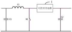
DC/DC升压电路包括第一电容C1、第一电感L1、第一可控开关K1、第二电容C2,以及串联在C1充电回路中的可控开关电路1。The DC/DC boost circuit includes a first capacitor C1, a first inductor L1, a first controllable switch K1, a second capacitor C2, and a
C1并联在DC/DC升压电路的输入端口,C2并联于DC/DC升压电路的输出端口,L1的一端连接DC/DC升压电路的正输入端,L1的另一端通过可控开关电路1连接DC/DC升压电路的正输出端。C1 is connected in parallel with the input port of the DC/DC booster circuit, C2 is connected in parallel with the output port of the DC/DC booster circuit, one end of L1 is connected to the positive input end of the DC/DC booster circuit, and the other end of L1 is connected through the
K1的一端连接L1与可控开关电路1的公共端,K1的另一端连接DC/DC升压电路的负输入端。One end of K1 is connected to the common end of L1 and the
控制单元用于当C1上的电压大于或等于第一电压阈值后,控制K1的开关状态,最终在C1上产生预设特征波形的控制信号。当K1导通时,C1处于放电状态;当K1关断时,C1不再放电,通过控制K1的控制信号占空比和开关频率中的至少一项,最终使C1产生预设特征波形。The control unit is used to control the switching state of K1 when the voltage on C1 is greater than or equal to the first voltage threshold, and finally generate a control signal of a preset characteristic waveform on C1. When K1 is turned on, C1 is in a discharge state; when K1 is turned off, C1 is no longer discharged. By controlling at least one of the control signal duty cycle of K1 and the switching frequency, C1 finally generates a preset characteristic waveform.
在一种应用场景中,随着C1放电,C1上的电压将越来越低,当C1上的电压低于某个阈值时,C1将无法产生预设特征波形的控制信号,此种情况下,需要为C1充电,以使C1的电压上升。在本实施例中,可以控制可控开关电路1中C2为C1充电的支路导通,以使C2为C1充电。C2为C1充电过程中,C2的电压下降,因此,此过程可以适当释放C2上的电压,从而降低C2过压的风险。In an application scenario, as C1 discharges, the voltage on C1 will become lower and lower. When the voltage on C1 is lower than a certain threshold, C1 will not be able to generate the control signal of the preset characteristic waveform. In this case , it is necessary to charge C1 so that the voltage of C1 rises. In this embodiment, the branch in the
在一种可能的实现方式中,可以检测C1的电压,当C1的电压低于第一电压阈值时,控制可控开关电路1中C2为C1充电的支路,从而使C2为C1充电。In a possible implementation manner, the voltage of C1 may be detected, and when the voltage of C1 is lower than the first voltage threshold, the branch of C2 in the
在另一种可能的实现方式中,每当控制K1断开后,都可以控制可控开关电路1内C2为C1充电的支路导通,C1放电和充电交替进行,从而避免C1上的电压过低无法产生预设特征波形。In another possible implementation, whenever the control K1 is turned off, the branch in the
本实施例提供的控制信号调制电路,基于DC/DC升压电路实现,DC/DC升压电路包括可控开关电路,通过该可控开关电路实现第二电容为第一电容充电的回路。当第一电容上的电压大于或等于第一电压阈值时,控制第一可控开关的开关状态,从而在第一电容上产生预设特征波形的控制信号。该方案是通过DC/DC升压电路中的第一电容的充放电过程产生预设特征波形的控制信号,因此不需要专用的信号发生器,而且不需要设置PLC通信模块,所以硬件成本低。而且,与无线通信方式相比,该方案产生的控制信号不受距离影响且不存在串扰现象,对安装现场地势无特殊要求。The control signal modulation circuit provided in this embodiment is implemented based on a DC/DC boost circuit, and the DC/DC boost circuit includes a controllable switch circuit through which a circuit in which the second capacitor charges the first capacitor is implemented. When the voltage on the first capacitor is greater than or equal to the first voltage threshold, the switching state of the first controllable switch is controlled, thereby generating a control signal with a preset characteristic waveform on the first capacitor. The solution is to generate a control signal with a preset characteristic waveform through the charging and discharging process of the first capacitor in the DC/DC boost circuit, so no dedicated signal generator is required, and no PLC communication module is required, so the hardware cost is low. Moreover, compared with the wireless communication method, the control signal generated by this scheme is not affected by distance and has no crosstalk phenomenon, and has no special requirements for the installation site terrain.
请参见图2,示出了本申请实施例提供的另一种控制信号调制电路的示意图,该信号调制电路基于典型的Boost电路得到。Referring to FIG. 2 , a schematic diagram of another control signal modulation circuit provided by an embodiment of the present application is shown, and the signal modulation circuit is obtained based on a typical Boost circuit.
如图2所示,典型的Boost电路包括:第一电容C1、第一电感L1、第一可控开关K1、第一单向导通器件D1和第二电容C2。C1并联于Boost电路的输入端口,C2并联于Boost电路的输出端口。L1和D1串联在Boost电路的输入端口正极与输出端口正极之间。K1的一端连接L1和D1的公共端,K1的另一端连接Boost电路的输入端口负极。K2并联于D1两端。As shown in FIG. 2 , a typical boost circuit includes: a first capacitor C1 , a first inductor L1 , a first controllable switch K1 , a first one-way conducting device D1 and a second capacitor C2 . C1 is connected in parallel with the input port of the Boost circuit, and C2 is connected in parallel with the output port of the Boost circuit. L1 and D1 are connected in series between the positive pole of the input port and the positive pole of the output port of the Boost circuit. One end of K1 is connected to the common end of L1 and D1, and the other end of K1 is connected to the negative pole of the input port of the Boost circuit. K2 is connected in parallel with both ends of D1.
Boost电路也称为Boost升压电路,是一种开关直流升压电路,能够使输入电压升高。Boost circuit, also known as Boost boost circuit, is a switching DC boost circuit that can boost the input voltage.
在典型Boost电路的基础上,增加第二可控开关K2,在一种可能的实现方式中,K2并联在D1的两端,即K2和D1组成图1所示实施例中的可控开关电路1。On the basis of the typical Boost circuit, a second controllable switch K2 is added. In a possible implementation, K2 is connected in parallel with both ends of D1, that is, K2 and D1 form the controllable switch circuit in the embodiment shown in FIG. 1 . 1.
K2的作用在于提供C2为C1充电的通道,当C1上的电压低于第一电压阈值时,控制K2闭合,此时C2上的能量通过K2和L1流向C1,即C2为C1充电。当C1的电压达到第一电压阈值后,通过控制K1的开关状态,控制C1充放电状态使C1上电压信号符合预设特征波形。The function of K2 is to provide a channel for C2 to charge C1. When the voltage on C1 is lower than the first voltage threshold, K2 is controlled to be closed. At this time, the energy on C2 flows to C1 through K2 and L1, that is, C2 charges C1. When the voltage of C1 reaches the first voltage threshold, by controlling the switching state of K1, the charging and discharging state of C1 is controlled so that the voltage signal on C1 conforms to the preset characteristic waveform.
其中,第一电压阈值可以根据C1的参数确定。具体的,在C1上的电压达到第一电压阈值的情况下,当需要产生控制信号时,控制K1闭合,此时C1放电,C1上的电压下降;按照预设的开关信号占空比及开关频率控制K1的开关状态,即可在C1上得到预设特征波形的控制信号。Wherein, the first voltage threshold may be determined according to the parameter of C1. Specifically, when the voltage on C1 reaches the first voltage threshold, when a control signal needs to be generated, control K1 to close, at this time C1 discharges, and the voltage on C1 drops; according to the preset switching signal duty cycle and switching The frequency controls the switching state of K1, and the control signal of the preset characteristic waveform can be obtained on C1.
光伏领域中,Boost电路输入端口连接的直流源通常是光伏组串,在光伏组串导通的情况下,可以通过光伏组串为C1充电,以使C1的电压上升。或者,控制K2闭合,由C2为C1充电,只要C2的电压高于C1的电压,都可以由C2为C1充电,不受直流侧的光伏组串是否导通的限制。In the photovoltaic field, the DC source connected to the input port of the boost circuit is usually a photovoltaic string. When the photovoltaic string is turned on, C1 can be charged through the photovoltaic string to increase the voltage of C1. Alternatively, control K2 to close, and C2 charges C1. As long as the voltage of C2 is higher than the voltage of C1, C2 can charge C1, regardless of whether the PV string on the DC side is turned on.
需要说明的是,可以在C1的电压低于第一电压阈值时,控制K2闭合,由C2为C1充电,或者,还可以每当控制K1断开后都控制K2闭合,由C2为C1充电。It should be noted that when the voltage of C1 is lower than the first voltage threshold, K2 can be controlled to close, and C2 can charge C1, or K2 can be controlled to close every time K1 is opened, and C2 can be charged for C1.
在本申请的另一种应用场景中,在控制K1的开关状态期间,可能会导致C2的电压过高超出安全阈值,此种情况下,可以控制K2闭合,释放C2上的电压,从而降低C2过压的风险。In another application scenario of the present application, during the control of the switching state of K1, the voltage of C2 may be too high to exceed the safety threshold. In this case, K2 can be controlled to close and the voltage on C2 can be released, thereby reducing C2 Risk of overvoltage.
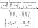
如图3所示,为本申请实施例提供的六种不同的特征波形。当然,还可以得到其他的特征波形本文不再一一展示。As shown in FIG. 3 , six different characteristic waveforms are provided in this embodiment of the present application. Of course, other characteristic waveforms can also be obtained and will not be shown one by one in this paper.
对于不同的控制信号,应选择不同的特征波形,可以预先指定每控制信号类型与特征波形之间的对应关系,并存储在控制单元中,当需要产生某一控制信号时,查找该对应关系得到相应的波形特征,进而产生符合该波形特征的控制信号。For different control signals, different characteristic waveforms should be selected. The corresponding relationship between each control signal type and the characteristic waveform can be pre-specified and stored in the control unit. When a certain control signal needs to be generated, the corresponding relationship can be obtained by searching Corresponding waveform characteristics, and then generate a control signal conforming to the waveform characteristics.
在本申请的另一个实施例中,如图4所示,K2还可以并联于L1和D1串联支路两端,图4所示的电路的工作原理与图1所示电路的工作原理相同,此处不再赘述。In another embodiment of the present application, as shown in FIG. 4 , K2 can also be connected in parallel to both ends of the series branch of L1 and D1. The working principle of the circuit shown in FIG. 4 is the same as that of the circuit shown in FIG. 1 . It will not be repeated here.
此外,K2开关瞬间存在一定的电流应力冲击,电流应力冲击会降低开关器件的使用寿命,为了避免这种现象发生,在本申请的又一个实施例中,如图4所示还可以增加与K2串联的限流器件,如电阻或电感等,从而降低K2开关瞬间产生的电流应力冲击。当然,还可以在图2所示实施例的基础上增加与K2串联的限流器件,此处不再赘述。In addition, there is a certain current stress shock instantaneously in the K2 switch, and the current stress shock will reduce the service life of the switching device. In order to avoid this phenomenon, in another embodiment of the present application, as shown in FIG. A series-connected current-limiting device, such as a resistor or an inductor, can reduce the current stress impact instantaneously generated by the K2 switch. Of course, a current limiting device connected in series with K2 can also be added on the basis of the embodiment shown in FIG. 2 , which will not be repeated here.
在本申请的又一个实施例中,如图5所示,可控开关电路为第三可控开关K3,本实施例中K1、K3的控制过程与图2和图4中的K1、K2的控制过程相同,此处不再赘述。In yet another embodiment of the present application, as shown in FIG. 5 , the controllable switch circuit is a third controllable switch K3. The control process of K1 and K3 in this embodiment is the same as that of K1 and K2 in FIG. 2 and FIG. 4 . The control process is the same and will not be repeated here.
本实施例提供的控制信号调制电路,基于典型Boost升压电路实现,在典型Boost升压电路的基础上增加第二可控开关,当第一电容上的电压低于第一电压阈值时,控制第二可控开关导通从而使第二电容为第一电容充电,直到第一电容上的电压达到第一电压阈值后,控制第一可控开关的开关状态,从而在第一电容上产生预设特征波形的控制信号。该方案是通过Boost升压电路中的第一电容的充放电过程产生预设特征波形的调制信号,因此不需要专用的信号发生器,而且不需要设置PLC通信模块,所以硬件成本低。而且,与无线通信方式相比,该方案产生的控制信号不受距离影响且不存在串扰现象,对安装现场地势无特殊要求。The control signal modulation circuit provided in this embodiment is implemented based on a typical boost boost circuit, and a second controllable switch is added on the basis of the typical boost boost circuit. When the voltage on the first capacitor is lower than the first voltage threshold, control the The second controllable switch is turned on so that the second capacitor charges the first capacitor. After the voltage on the first capacitor reaches the first voltage threshold, the switching state of the first controllable switch is controlled, thereby generating a pre-condition on the first capacitor. Set the control signal of the characteristic waveform. The scheme generates a modulation signal with a preset characteristic waveform through the charging and discharging process of the first capacitor in the boost circuit, so no special signal generator is required, and no PLC communication module is required, so the hardware cost is low. Moreover, compared with the wireless communication method, the control signal generated by this scheme is not affected by distance and has no crosstalk phenomenon, and has no special requirements for the installation site terrain.
上述实施例中,由DC/DC升压电路中的C2为C1充电,以使C1的电压达到产生预设特征波形所需的电压水平。在本申请的另一个实施例中,还可以通过直流供电电路为C1充电。In the above embodiment, C1 is charged by C2 in the DC/DC boost circuit, so that the voltage of C1 reaches the voltage level required for generating the preset characteristic waveform. In another embodiment of the present application, C1 can also be charged through a DC power supply circuit.
请参见图6,示出了本申请实施例提供的又一种控制信号调制电路的示意图,本实施例提供的调制电路基于DC/DC升压电路实现,与图2、图4、图5所示实施例的不同之处在于,本实施例采用直流供电电路作为C1的充电能量来源。Referring to FIG. 6 , a schematic diagram of another control signal modulation circuit provided by an embodiment of the present application is shown. The modulation circuit provided by this embodiment is implemented based on a DC/DC boost circuit, which is the same as the one shown in FIG. 2 , FIG. 4 , and FIG. 5 . The difference between the illustrated embodiment is that this embodiment adopts a DC power supply circuit as the charging energy source of C1.
如图6所示,该控制信号调制电路包括直流供电电路110、第二单向单通器件D2、第四可控开关K4、DC/DC升压电路120和控制单元。As shown in FIG. 6 , the control signal modulation circuit includes a DC
其中,本实施例中的DC/DC升压电路120可以采用图2、图4和图5所示的任一种DC/DC升压拓扑,此处不再赘述。本实施例将以DC/DC升压电路120采用图2所示的电路为例进行说明。The DC/
直流供电电路110的输出端依次串联第四可控开关K4和第二单向导通器件D2后连接至DC/DC升压电路120的输入端口。The output end of the DC
本实施例中,D2的连接方向使所述直流供电电路输出的电能流向所述DC/DC升压电路的输入端口,从而防止能量反向传输In this embodiment, the connection direction of D2 makes the electric energy output by the DC power supply circuit flow to the input port of the DC/DC boost circuit, thereby preventing the reverse transmission of energy
在本申请的一个实施例中,直流供电电路110可以采用逆变电路实现,逆变电路的交流侧连接交流电源。In an embodiment of the present application, the DC
当C1的电压大于或等于第一电压阈值后,通过控制K1的开关控制信号占空比及开关频率中的至少一项,以使C1产生预设特征波形的控制信号。When the voltage of C1 is greater than or equal to the first voltage threshold, at least one of the duty ratio and switching frequency of the switch control signal of K1 is controlled, so that C1 generates a control signal with a preset characteristic waveform.
在本申请一种可能的实现方式中,当C1上的电压低于第一电压阈值时,控制K4闭合以使直流供电电路110为C1充电。In a possible implementation manner of the present application, when the voltage on C1 is lower than the first voltage threshold, K4 is controlled to be closed so that the DC
在本申请另一种可能的实现方式中,可以在控制K1关断后,控制K4闭合,由直流供电电路为C1充电。In another possible implementation manner of the present application, after K1 is controlled to be turned off, K4 can be controlled to be closed, and the DC power supply circuit can charge C1.
在本申请的另一个实施例中,为了避免C2上的电压过高超过安全阈值,当检测到C2上的电压高于第二电压阈值后,控制K2闭合,以使C2放电,降低C2过压的风险。In another embodiment of the present application, in order to prevent the voltage on C2 from being too high and exceeding the safety threshold, when it is detected that the voltage on C2 is higher than the second voltage threshold, control K2 to close to discharge C2 and reduce the overvoltage of C2 risks of.
当然,在其它实施例中,当C2上的电压超过第二电压阈值后,还可以控制电路中的直流负载(如,风扇等)工作,消耗C2的能量,同样能够降低C2过压的风险。Of course, in other embodiments, when the voltage on C2 exceeds the second voltage threshold, the DC load (eg, fan, etc.) in the circuit can also be controlled to work, consuming the energy of C2, and also reducing the risk of overvoltage of C2.
在本申请的一个实施例中,在该控制信号调制电路应用于逆变器的应用场景中,该直流供电电路110可以是逆变器中原有的供电电路,例如,为自身的直流负载(如,风扇等)供电的供电电路,其中,供电电压可以是+24V等。当然,在其他实施例中,也可以使用独立于逆变器自身原有直流供电电路之外单独直流供电,此处不再赘述。In an embodiment of the present application, in an application scenario where the control signal modulation circuit is applied to an inverter, the DC
本实施例提供的控制信号调制电路,直流供电电路作为C1充电的能量来源,当第一电容上的电压低于第一电压阈值时,控制第四可控开关电路导通从而使直流供电电路为第一电容充电。当第一电容上的电压达到第一电压阈值时,控制第一可控开关的开关状态以控制第一电容的充放电状态,从而在第一电容上产生预设特征波形的控制信号。该方案利用直流供电电路为第一电容充电,不会对C2产生影响,从而提高了DC/DC升压电路的可靠性。In the control signal modulation circuit provided by this embodiment, the DC power supply circuit is used as the energy source for charging C1, and when the voltage on the first capacitor is lower than the first voltage threshold, the fourth controllable switch circuit is controlled to be turned on, so that the DC power supply circuit is The first capacitor is charged. When the voltage on the first capacitor reaches the first voltage threshold, the switching state of the first controllable switch is controlled to control the charging and discharging state of the first capacitor, thereby generating a control signal with a preset characteristic waveform on the first capacitor. The scheme uses the DC power supply circuit to charge the first capacitor without affecting C2, thereby improving the reliability of the DC/DC boost circuit.
另一方面,本申请实施例还提供了应用上述控制信号调制电路的逆变器。On the other hand, the embodiments of the present application also provide an inverter applying the above-mentioned control signal modulation circuit.
请参见图7,示出了本申请实施例提供的一种逆变器的结构示意图,本实施例以单输入型逆变器为例进行说明。Referring to FIG. 7 , a schematic structural diagram of an inverter provided by an embodiment of the present application is shown. This embodiment is described by taking a single-input inverter as an example.
如图7所示,该逆变器包括控制信号调制电路210、逆变电路220和逆变控制器;As shown in FIG. 7 , the inverter includes a control
其中,该控制信号调制电路210在逆变器自身已有的Boost电路基础上增加第二可控开关K2得到,即该控制信号调制电路210采用图2所示电路实现。其中,Boost电路包括C1、L1、K1、D1和C2。The control
本实施例中,K2并联于Boost电路中的D1两端,Boost电路的输出端口连接逆变电路220的直流端口,Boost电路的输入端口用于连接光伏组串。In this embodiment, K2 is connected in parallel to both ends of D1 in the Boost circuit, the output port of the Boost circuit is connected to the DC port of the
逆变控制器获得控制信号生成指令,并发送至所述控制信号调制电路内的控制单元。The inverter controller obtains the control signal generation instruction and sends it to the control unit in the control signal modulation circuit.
控制单元,用于当C1的电压大于或等于第一电压阈值时,控制K2关断,并控制K1的开关状态,以使C1产生预设特征波形的控制信号。The control unit is configured to control K2 to turn off when the voltage of C1 is greater than or equal to the first voltage threshold, and control the switching state of K1, so that C1 generates a control signal of a preset characteristic waveform.
其中,控制信号用于使光伏组串内的控制单元解析得到相应的控制指令并执行该控制指令。Wherein, the control signal is used to make the control unit in the photovoltaic string parse to obtain the corresponding control command and execute the control command.
控制单元,还用于当C1的电压低于第一电压阈值时,控制K2闭合以使C2为C1充电。The control unit is further configured to control K2 to be closed so that C2 charges C1 when the voltage of C1 is lower than the first voltage threshold.
此外,控制单元可以集成于逆变控制器中,或者,也可以是独立逆变控制器的控制单元。In addition, the control unit may be integrated in the inverter controller, or may also be a control unit of an independent inverter controller.
在一种应用场景中,逆变器需要产生控制光伏组件导通或关断的控制信号,此种应用场景下控制单元具体用于:In an application scenario, the inverter needs to generate a control signal to control the turn-on or turn-off of photovoltaic modules. In this application scenario, the control unit is specifically used for:
在光伏组串处于导通状态时,C1两端电压为光伏组串的电压U1,且U1>0。此时,若逆变控制器获得关断指令(例如,在检测到外部DI接口接收到相应按钮的触发信号后产生),逆变器关机,同时,逆变控制器产生关断信号生成指令发送至控制信号调制电路中的控制单元。控制单元接收到关断信号生成指令后控制K2关断,且K1闭合,由于光伏组串正极和负极之间并联C1,L1与C1并联,,C1通过L1放电,C1上的电压下降;当K1断开后,光伏组串给C1充电,C1上的电压上升。或者,也可以控制K2闭合,由C2为C1充电,以使C1上的电压上升。按照预设的开关控制信号占空比及开关频率控制K1的开关状态,即可在C1上得到第一预设特征波形的关断控制信号。When the photovoltaic string is in an on state, the voltage across C1 is the voltage U1 of the photovoltaic string, and U1>0. At this time, if the inverter controller obtains a shutdown command (for example, it is generated after detecting that the external DI interface receives the trigger signal of the corresponding button), the inverter will shutdown, and at the same time, the inverter controller will generate a shutdown signal to generate a command to send to the control unit in the control signal modulation circuit. After the control unit receives the shutdown signal generation command, it controls K2 to be turned off and K1 to be closed. Since C1 is connected in parallel between the positive and negative poles of the photovoltaic string, and L1 is connected in parallel with C1, C1 discharges through L1, and the voltage on C1 drops; when K1 After disconnection, the PV string charges C1, and the voltage on C1 rises. Alternatively, K2 can be controlled to close, and C2 can charge C1, so that the voltage on C1 rises. The switch state of K1 is controlled according to the preset duty cycle and switching frequency of the switch control signal, and the turn-off control signal of the first preset characteristic waveform can be obtained on C1.
光伏组串处于关断状态,C1上的电压几乎为0,当逆变控制器接收到导通指令产生导通信号生成指令并发送至控制单元。由于光伏组串处于关断状态,无法通过光伏组串为C1充电,因此,控制单元在接收到导通信号指令后,需要先通过交流侧电网为直流母线预充电,以提升直流母线电压,然后,控制K1断开,K2闭合,此时,C2为C1充电,当C1上的电压达到第一电压阈值时,再控制K1的开关状态,即可在C1上得到第二预设特征波形的导通控制信号。The photovoltaic string is in the off state, and the voltage on C1 is almost 0. When the inverter controller receives the turn-on command, it generates a turn-on signal and sends it to the control unit. Since the PV strings are in the off state, C1 cannot be charged through the PV strings. Therefore, after receiving the turn-on signal command, the control unit needs to pre-charge the DC bus through the AC side grid to increase the DC bus voltage, and then , control K1 to open and K2 to close. At this time, C2 charges C1. When the voltage on C1 reaches the first voltage threshold, the switch state of K1 is controlled again, and the second preset characteristic waveform can be obtained on C1. pass the control signal.
其中,关断控制信号的波形可以是图3中的任意一种特征波形,当然也可以是图3未示出的其它特征波形;导通控制信号可以是不同于关断控制信号的波形特征的其它波形特征,本申请对此不做限定。Wherein, the waveform of the turn-off control signal can be any one of the characteristic waveforms in FIG. 3, and of course it can also be other characteristic waveforms not shown in FIG. 3; the turn-on control signal can be different from the waveform characteristics of the turn-off control signal Other waveform features are not limited in this application.
在本申请的另一个实施例中,为了降低K2开关瞬间产生的电流应力冲击,还可以增加与K2串联的限流器件,如电阻或电感等。In another embodiment of the present application, in order to reduce the current stress impact instantaneously generated by the K2 switch, a current limiting device, such as a resistor or an inductor, etc., may be added in series with the K2.
在本申请的又一个实施例中,如图8所示,K2(或K2和限流器件的串联支路)还可以并联在L1和D1的串联支路两端,产生控制信号的调制过程与图7所示逆变器的调制过程相同,此处不再赘述。In another embodiment of the present application, as shown in FIG. 8 , K2 (or the series branch of K2 and the current limiting device) can also be connected in parallel at both ends of the series branch of L1 and D1, and the modulation process for generating the control signal is the same as The modulation process of the inverter shown in FIG. 7 is the same, and will not be repeated here.
在本申请的另一种应用场景中,逆变器包括多组直流输入端,下面以两对输入端为例进行说明。In another application scenario of the present application, the inverter includes multiple sets of DC input terminals, and two pairs of input terminals are used as an example for description below.
如图9所示,两个Boost电路的输出端口并联,即第一Boost电路310的正、负输出端分别连接第二Boost电路320的正、负输出端。而且,两个Boost电路共用一个可控开关K2(即第二可控开关)、限流器件。As shown in FIG. 9 , the output ports of the two Boost circuits are connected in parallel, that is, the positive and negative output terminals of the
K2的一端与第一Boost电路310和第二Boost电路320的正输出端,K2的另一端通过D2连接第一Boost电路310的正极输入端,同时,K2的另一端还通过D21连接第二Boost电路320的正极输入端。One end of K2 is connected to the positive output end of the
在本申请的另一个实施例中,第二可控开关K2并联在各个Boost电路的第一单向导通器件两端,如图10所示,K2的一端连接至各个Boost电路的正极输出端,K2的另一端通过D2连接第一Boost电路310中L1和D1的公共端,同时,K2的另一端还通过D21连接第二Boost电路320中L2和D11的公共端。In another embodiment of the present application, the second controllable switch K2 is connected in parallel to both ends of the first unidirectional conducting device of each Boost circuit. As shown in FIG. 10 , one end of K2 is connected to the positive output end of each Boost circuit, The other end of K2 is connected to the common end of L1 and D1 in the
图9和图10中的D2和D21的作用是单向导通,只允许能量从C2流向C1,以及,能量只能从C21流向C11,防止其他Boost电路中电能流向本Boost电路中。The functions of D2 and D21 in Figure 9 and Figure 10 are unidirectional conduction, only allowing energy to flow from C2 to C1, and energy can only flow from C21 to C11, preventing other Boost circuits from flowing to this Boost circuit.
图9和图10所示的逆变器的电路中,各个Boost电路共用K2和限流器件,因此,进一步降低了硬件成本。In the inverter circuits shown in FIG. 9 and FIG. 10 , each boost circuit shares K2 and the current limiting device, thus further reducing the hardware cost.
本实施例提供的逆变器,通过控制Boost电路中的可控开关的开关状态,在Boost电路输入端口并联的第一电容上得到不同波形特征的控制信号;当第一电容的电压低于第一电压阈值时,控制第二可控开关闭合以使第二电容为第一电容充电,从而确保第一电容产生的波形特征不受影响。该方案利用改进后的Boost电路调制得到相应的控制信号,并通过原有的传输线路传输控制信号。该方案的控制信号传输不受距离影响且不存在串扰现象,对安装现场地势无特殊要求,而且不需要设置PLC通信模块或单独的信号发生器,因此,硬件成本低。The inverter provided by this embodiment obtains control signals with different waveform characteristics on the first capacitor connected in parallel with the input port of the boost circuit by controlling the switching state of the controllable switch in the boost circuit; when the voltage of the first capacitor is lower than the first capacitor At a voltage threshold, the second controllable switch is controlled to be closed so that the second capacitor charges the first capacitor, thereby ensuring that the waveform characteristics generated by the first capacitor are not affected. The scheme uses the improved Boost circuit to modulate to obtain the corresponding control signal, and transmits the control signal through the original transmission line. The control signal transmission of this scheme is not affected by distance and there is no crosstalk phenomenon, there are no special requirements for the installation site terrain, and there is no need to set up a PLC communication module or a separate signal generator, so the hardware cost is low.
相应于图6所示的控制信号调制电路,本申请实施例还提供了应用该调制电路的逆变器。Corresponding to the control signal modulation circuit shown in FIG. 6 , the embodiment of the present application also provides an inverter applying the modulation circuit.
请参见图11,示出了本申请实施例提供的又一种逆变器的结构示意图,该逆变器包括:控制信号调制电路410、升压电路420和逆变电路430。Referring to FIG. 11 , a schematic structural diagram of another inverter provided by an embodiment of the present application is shown. The inverter includes: a control
其中,控制信号调制电路410包括直流供电电路411、可控开关K、第三单向导通器件D和控制单元。Wherein, the control
直流供电电路411的直流输出端口依次串联K和D后,连接至升压电路420的直流输入端口,直流供电电路411的交流端连接交流电源。The DC output port of the DC
利用控制单元控制DC/DC升压电路420中第一可控开关K1,从而在DC/DC升压电路420内的第一电容上得到预设特征波形的控制信号。The control unit is used to control the first controllable switch K1 in the DC/
当DC/DC升压电路420中C1的电压低于第一电压阈值时,或者,当控制K1断开后,控制K闭合,以使直流供电电路411为C1充电,提升C1上的电压。When the voltage of C1 in the DC/
其中,本实施例控制信号调制电路的控制单元可以集成在逆变控制器中,或者,也可以是独立逆变控制器的控制单元。Wherein, the control unit of the control signal modulation circuit in this embodiment may be integrated in the inverter controller, or may also be a control unit of an independent inverter controller.
本实施例提供的逆变器,通过直流供电电路作为第一电容充电的能量来源,当第一电容上的电压低于第一电压阈值时,控制第四可控开关电路导通从而使直流供电电路为第一电容充电;当第一电容上的电压达到第一电压阈值时,控制第一可控开关的开关状态以控制第一电容的充放电状态,从而在第一电容上产生预设特征波形的控制信号。该方案利用直流供电电路为第一电容充电,不会对第二电容产生影响,提高了逆变器的可靠性。In the inverter provided in this embodiment, the DC power supply circuit is used as the energy source for charging the first capacitor, and when the voltage on the first capacitor is lower than the first voltage threshold, the fourth controllable switch circuit is controlled to be turned on so as to enable the DC power supply The circuit charges the first capacitor; when the voltage on the first capacitor reaches the first voltage threshold, the switching state of the first controllable switch is controlled to control the charging and discharging state of the first capacitor, thereby generating a preset characteristic on the first capacitor Waveform control signal. The solution uses the DC power supply circuit to charge the first capacitor without affecting the second capacitor, thereby improving the reliability of the inverter.
又一方面,本申请实施例还提供了光伏组串控制系统。In another aspect, the embodiments of the present application further provide a photovoltaic string control system.
请参见图12,示出了本申请实施例提供的一种光伏组串控制系统的结构示意图,本实施例基于图7所示的逆变器实现对光伏组串的控制。Referring to FIG. 12 , a schematic structural diagram of a photovoltaic string control system provided by an embodiment of the present application is shown. This embodiment implements control of photovoltaic strings based on the inverter shown in FIG. 7 .
如图12所示,光伏组串控制系统包括逆变器610和光伏组串620;As shown in FIG. 12 , the photovoltaic string control system includes an inverter 610 and a photovoltaic string 620;
其中,光伏组串620包括n个串联的光伏组件PV1~PVn,以及,与每个光伏组件的输出端连接的关断器RSD1~RSDn;Wherein, the photovoltaic string 620 includes n photovoltaic modules PV1-PVn connected in series, and a switch RSD1-RSDn connected to the output end of each photovoltaic module;
通过n个RSD(Rapid Shutdown,快速关断)依次串联实现n个光伏组件依次串联。The series connection of n photovoltaic modules is realized through the series connection of n RSDs (Rapid Shutdown, rapid shutdown).
光伏组串620中的每个关断器均串联于逆变器610的直流侧,每个关断器接收逆变器输出的控制信号后,解析该控制信号获得相应的控制指令并执行该控制指令对应的操作。Each switch in the photovoltaic string 620 is connected in series with the DC side of the inverter 610. After receiving the control signal output by the inverter, each switch parses the control signal to obtain a corresponding control command and executes the control The operation corresponding to the command.
如图13所示,示出了一种关断器内部的结构示意图,该关断器包括解析模块710、控制器720、开关管S。As shown in FIG. 13 , a schematic diagram of the internal structure of a switch is shown, and the switch includes an
在控制光伏组件导通或关断的应用场景中,关断器的具体控制过程如下:In the application scenario of controlling the turn-on or turn-off of photovoltaic modules, the specific control process of the circuit breaker is as follows:
当解析模块710解析逆变器输出的控制信号的波形特征符合第一预设特征波形时,确定控制信号为关断控制信号,并由控制器720控制开关管S关断,进而使与S连接的光伏组件与逆变器断开。When the
以及,当解析模块710解析所述逆变器输出的控制信号的波形特征符合第二预设特征波形时,确定所述控制信号为导通控制信号,并由控制器720控制开关管S导通,进而使与开关管S连接的光伏组件与逆变器连接。And, when the
在本申请的另一个实施例中,光伏组件内设置的控制用于接收逆变器发送的控制信号,解析所述逆变器输出的控制信号的波形特征符合第三预设特征波形时,确定控制信号为监控信号,并向逆变器上传光伏组件的相应状态数据。In another embodiment of the present application, the control set in the photovoltaic module is used to receive the control signal sent by the inverter, and when analyzing the waveform characteristics of the control signal output by the inverter conforms to the third preset characteristic waveform, determine The control signal is a monitoring signal and uploads the corresponding status data of the PV modules to the inverter.
在本申请的其它实施例中,光伏组件控制系统还可以基于本申请提供的其它逆变器(如图8-图11所示的逆变器)实现对光伏组件的控制,光伏组件侧解析逆变器发送的控制信号的过程与上述解析过程相似,此处不再赘述。In other embodiments of the present application, the photovoltaic module control system may also control the photovoltaic modules based on other inverters provided in the present application (inverters shown in FIG. 8 to FIG. 11 ). The process of the control signal sent by the converter is similar to the above-mentioned analysis process, and will not be repeated here.
本实施例提供的光伏组件控制系统,通过逆变器内改进后的电路调制产生控制信号,并传输至光伏组件侧。光伏组件解析接收到的控制信号得到相应的控制指令,进而依据该控制指令执行相应的操作。该系统中控制信号的传输不受距离影响且不存在串扰现象,以及对安装现场地势无特殊要求,而且不需要设置PLC通信模块或单独的信号发生器,因此,硬件成本低。The photovoltaic module control system provided in this embodiment generates a control signal through the improved circuit modulation in the inverter, and transmits it to the photovoltaic module side. The photovoltaic module parses the received control signal to obtain the corresponding control command, and then executes the corresponding operation according to the control command. The transmission of the control signal in the system is not affected by distance and there is no crosstalk phenomenon, and there is no special requirement for the installation site terrain, and there is no need to set up a PLC communication module or a separate signal generator, so the hardware cost is low.
对于前述的各方法实施例,为了简单描述,故将其都表述为一系列的动作组合,但是本领域技术人员应该知悉,本发明并不受所描述的动作顺序的限制,因为依据本发明,某些步骤可以采用其他顺序或者同时进行。其次,本领域技术人员也应该知悉,说明书中所描述的实施例均属于优选实施例,所涉及的动作和模块并不一定是本发明所必须的。For the foregoing method embodiments, for the sake of simple description, they are all expressed as a series of action combinations, but those skilled in the art should know that the present invention is not limited by the described action sequence, because according to the present invention, Certain steps may be performed in other orders or simultaneously. Secondly, those skilled in the art should also know that the embodiments described in the specification are all preferred embodiments, and the actions and modules involved are not necessarily required by the present invention.
需要说明的是,本说明书中的各个实施例均采用递进的方式描述,每个实施例重点说明的都是与其他实施例的不同之处,各个实施例之间相同相似的部分互相参见即可。对于装置类实施例而言,由于其与方法实施例基本相似,所以描述的比较简单,相关之处参见方法实施例的部分说明即可。It should be noted that the various embodiments in this specification are described in a progressive manner, and each embodiment focuses on the differences from other embodiments. For the same and similar parts among the various embodiments, refer to each other Can. As for the apparatus type embodiment, since it is basically similar to the method embodiment, the description is relatively simple, and for the relevant part, please refer to the partial description of the method embodiment.
本申请各实施例方法中的步骤可以根据实际需要进行顺序调整、合并和删减。The steps in the methods of the embodiments of the present application may be adjusted, combined and deleted in sequence according to actual needs.
本申请各实施例中的装置及终端中的模块和子模块可以根据实际需要进行合并、划分和删减。Modules and sub-modules in the apparatus and terminal in each embodiment of the present application may be combined, divided, and deleted according to actual needs.
本申请所提供的几个实施例中,应该理解到,所揭露的终端,装置和方法,可以通过其它的方式实现。例如,以上所描述的终端实施例仅仅是示意性的,例如,模块或子模块的划分,仅仅为一种逻辑功能划分,实际实现时可以有另外的划分方式,例如多个子模块或模块可以结合或者可以集成到另一个模块,或一些特征可以忽略,或不执行。另一点,所显示或讨论的相互之间的耦合或直接耦合或通信连接可以是通过一些接口,装置或模块的间接耦合或通信连接,可以是电性,机械或其它的形式。In the several embodiments provided in this application, it should be understood that the disclosed terminal, apparatus and method may be implemented in other manners. For example, the terminal embodiments described above are only illustrative. For example, the division of modules or sub-modules is only a logical function division. In actual implementation, there may be other division methods. For example, multiple sub-modules or modules may be combined. Or it can be integrated into another module, or some features can be ignored, or not implemented. On the other hand, the shown or discussed mutual coupling or direct coupling or communication connection may be through some interfaces, indirect coupling or communication connection of devices or modules, and may be in electrical, mechanical or other forms.
作为分离部件说明的模块或子模块可以是或者也可以不是物理上分开的,作为模块或子模块的部件可以是或者也可以不是物理模块或子模块,即可以位于一个地方,或者也可以分布到多个网络模块或子模块上。可以根据实际的需要选择其中的部分或者全部模块或子模块来实现本实施例方案的目的。A module or sub-module described as a separate component may or may not be physically separate, and a component that is a module or sub-module may or may not be a physical module or sub-module, that is, it may be located in one place, or it may be distributed to on multiple network modules or submodules. Some or all of the modules or sub-modules may be selected according to actual needs to achieve the purpose of the solution in this embodiment.
另外,在本申请各个实施例中的各功能模块或子模块可以集成在一个处理模块中,也可以是各个模块或子模块单独物理存在,也可以两个或两个以上模块或子模块集成在一个模块中。上述集成的模块或子模块既可以采用硬件的形式实现,也可以采用软件功能模块或子模块的形式实现。In addition, each functional module or sub-module in each embodiment of the present application may be integrated into one processing module, or each module or sub-module may exist physically alone, or two or more modules or sub-modules may be integrated in one processing module. in a module. The above-mentioned integrated modules or sub-modules may be implemented in the form of hardware, and may also be implemented in the form of software function modules or sub-modules.
最后,还需要说明的是,在本文中,诸如第一和第二等之类的关系术语仅仅用来将一个实体或者操作与另一个实体或操作区分开来,而不一定要求或者暗示这些实体或操作之间存在任何这种实际的关系或者顺序。而且,术语“包括”、“包含”或者其任何其他变体意在涵盖非排他性的包含,从而使得包括一系列要素的过程、方法、物品或者设备不仅包括那些要素,而且还包括没有明确列出的其他要素,或者是还包括为这种过程、方法、物品或者设备所固有的要素。在没有更多限制的情况下,由语句“包括一个……”限定的要素,并不排除在包括所述要素的过程、方法、物品或者设备中还存在另外的相同要素。Finally, it should also be noted that in this document, relational terms such as first and second are used only to distinguish one entity or operation from another, and do not necessarily require or imply these entities or that there is any such actual relationship or sequence between operations. Moreover, the terms "comprising", "comprising" or any other variation thereof are intended to encompass non-exclusive inclusion such that a process, method, article or device comprising a list of elements includes not only those elements, but also includes not explicitly listed or other elements inherent to such a process, method, article or apparatus. Without further limitation, an element qualified by the phrase "comprising a..." does not preclude the presence of additional identical elements in a process, method, article or apparatus that includes the element.
对所公开的实施例的上述说明,使本领域技术人员能够实现或使用本发明。对这些实施例的多种修改对本领域技术人员来说将是显而易见的,本文中所定义的一般原理可以在不脱离本发明的精神或范围的情况下,在其它实施例中实现。因此,本发明将不会被限制于本文所示的这些实施例,而是要符合与本文所公开的原理和新颖特点相一致的最宽的范围。The above description of the disclosed embodiments enables any person skilled in the art to make or use the present invention. Various modifications to these embodiments will be readily apparent to those skilled in the art, and the generic principles defined herein may be implemented in other embodiments without departing from the spirit or scope of the invention. Thus, the present invention is not intended to be limited to the embodiments shown herein, but is to be accorded the widest scope consistent with the principles and novel features disclosed herein.
以上所述仅是本发明的优选实施方式,应当指出,对于本技术领域的普通技术人员来说,在不脱离本发明原理的前提下,还可以做出若干改进和润饰,这些改进和润饰也应视为本发明的保护范围。The above are only the preferred embodiments of the present invention. It should be pointed out that for those skilled in the art, without departing from the principles of the present invention, several improvements and modifications can be made. It should be regarded as the protection scope of the present invention.
Claims (13)
Priority Applications (5)
| Application Number | Priority Date | Filing Date | Title |
|---|---|---|---|
| CN202010001498.9ACN113067473B (en) | 2020-01-02 | 2020-01-02 | Control signal modulation circuit, inverter and control system |
| PCT/CN2020/139343WO2021136085A1 (en) | 2020-01-02 | 2020-12-25 | Control signal modulation circuit, inverter, and control system |
| US17/608,445US11652412B2 (en) | 2020-01-02 | 2020-12-25 | Control signal modulation circuit, inverter, and control system |
| CA3136856ACA3136856C (en) | 2020-01-02 | 2020-12-25 | Control signal modulation circuit, inverter, and control system |
| EP20910353.0AEP4087107B1 (en) | 2020-01-02 | 2020-12-25 | Control signal modulation circuit, inverter, and control system |
Applications Claiming Priority (1)
| Application Number | Priority Date | Filing Date | Title |
|---|---|---|---|
| CN202010001498.9ACN113067473B (en) | 2020-01-02 | 2020-01-02 | Control signal modulation circuit, inverter and control system |
Publications (2)
| Publication Number | Publication Date |
|---|---|
| CN113067473Atrue CN113067473A (en) | 2021-07-02 |
| CN113067473B CN113067473B (en) | 2022-05-24 |
Family
ID=76558104
Family Applications (1)
| Application Number | Title | Priority Date | Filing Date |
|---|---|---|---|
| CN202010001498.9AActiveCN113067473B (en) | 2020-01-02 | 2020-01-02 | Control signal modulation circuit, inverter and control system |
Country Status (5)
| Country | Link |
|---|---|
| US (1) | US11652412B2 (en) |
| EP (1) | EP4087107B1 (en) |
| CN (1) | CN113067473B (en) |
| CA (1) | CA3136856C (en) |
| WO (1) | WO2021136085A1 (en) |
Families Citing this family (1)
| Publication number | Priority date | Publication date | Assignee | Title |
|---|---|---|---|---|
| US12382520B2 (en)* | 2022-11-11 | 2025-08-05 | Tigo Energy, Inc. | Solar panel transmitter pairing process |
Citations (4)
| Publication number | Priority date | Publication date | Assignee | Title |
|---|---|---|---|---|
| US20080285317A1 (en)* | 2007-05-17 | 2008-11-20 | Larankelo, Inc. | Photovoltaic module-mounted ac inverter |
| CN108054998A (en)* | 2017-12-26 | 2018-05-18 | 深圳古瑞瓦特新能源股份有限公司 | Optimizer, photovoltaic power generation system and photovoltaic power generation control method |
| CN109412406A (en)* | 2017-08-18 | 2019-03-01 | 丰郅(上海)新能源科技有限公司 | The voltage conversion circuit applied to photovoltaic module of integrated carrier wave sending function |
| CN209120129U (en)* | 2018-11-15 | 2019-07-16 | 上海谦牧信息技术有限公司 | A kind of tandem component level photovoltaic turning off system |
Family Cites Families (8)
| Publication number | Priority date | Publication date | Assignee | Title |
|---|---|---|---|---|
| DE102006060815B4 (en)* | 2006-09-21 | 2013-05-29 | Solarworld Innovations Gmbh | Solar power generation plant |
| CN105244905B (en)* | 2007-12-05 | 2019-05-21 | 太阳能安吉有限公司 | Release mechanism in distributed power device is waken up and method for closing |
| US10476372B2 (en)* | 2014-12-22 | 2019-11-12 | Futurewei Technologies, Inc. | Buck-boost power converter and method of operation thereof |
| CN107070190B (en)* | 2017-04-26 | 2020-06-09 | 华为技术有限公司 | Power supply device and capacitance heating control method thereof |
| CN106911260A (en)* | 2017-04-26 | 2017-06-30 | 阳光电源股份有限公司 | A kind of control method of multi-electrical level inverter, device and inverter |
| CN107017767B (en)* | 2017-04-27 | 2019-07-19 | 华为技术有限公司 | Method and device for open-circuit overvoltage protection of solar cell array, and inverter |
| DE102018201925A1 (en) | 2018-02-07 | 2019-08-08 | Würth Elektronik eiSos Gmbh & Co. KG | Apparatus for obtaining electrical energy and energy producers with such a device |
| CN108988635B (en)* | 2018-09-13 | 2019-09-20 | 阳光电源股份有限公司 | A kind of more level Boost converters, inversion system and control method |
- 2020
- 2020-01-02CNCN202010001498.9Apatent/CN113067473B/enactiveActive
- 2020-12-25CACA3136856Apatent/CA3136856C/enactiveActive
- 2020-12-25WOPCT/CN2020/139343patent/WO2021136085A1/ennot_activeCeased
- 2020-12-25EPEP20910353.0Apatent/EP4087107B1/enactiveActive
- 2020-12-25USUS17/608,445patent/US11652412B2/enactiveActive
Patent Citations (4)
| Publication number | Priority date | Publication date | Assignee | Title |
|---|---|---|---|---|
| US20080285317A1 (en)* | 2007-05-17 | 2008-11-20 | Larankelo, Inc. | Photovoltaic module-mounted ac inverter |
| CN109412406A (en)* | 2017-08-18 | 2019-03-01 | 丰郅(上海)新能源科技有限公司 | The voltage conversion circuit applied to photovoltaic module of integrated carrier wave sending function |
| CN108054998A (en)* | 2017-12-26 | 2018-05-18 | 深圳古瑞瓦特新能源股份有限公司 | Optimizer, photovoltaic power generation system and photovoltaic power generation control method |
| CN209120129U (en)* | 2018-11-15 | 2019-07-16 | 上海谦牧信息技术有限公司 | A kind of tandem component level photovoltaic turning off system |
Also Published As
| Publication number | Publication date |
|---|---|
| CA3136856A1 (en) | 2021-07-08 |
| EP4087107A4 (en) | 2024-01-03 |
| CN113067473B (en) | 2022-05-24 |
| CA3136856C (en) | 2023-09-05 |
| US11652412B2 (en) | 2023-05-16 |
| US20220216786A1 (en) | 2022-07-07 |
| EP4087107B1 (en) | 2025-08-13 |
| EP4087107C0 (en) | 2025-08-13 |
| WO2021136085A1 (en) | 2021-07-08 |
| EP4087107A1 (en) | 2022-11-09 |
Similar Documents
| Publication | Publication Date | Title |
|---|---|---|
| CN109245713B (en) | Series-type assembly-level photovoltaic shutdown system | |
| CN103915856B (en) | A kind of base station is grid-connected-charging photovoltaic micro-inverter system and control method thereof | |
| TW201332268A (en) | Discharge circuit and converter | |
| CN102969912A (en) | Control and drive circuit and method | |
| CN110789400A (en) | Wireless charging-heating integrated system for battery, control method and battery system | |
| CN104901401A (en) | Charging method and charging system | |
| CN105958934B (en) | Power optimizer | |
| CN104242349A (en) | Photovoltaic system with potential induced degradation prevention function and photovoltaic inverter | |
| CN103947068A (en) | Single phase inverters cooperatively controlled to provide one, two, or three phase unipolar electricity | |
| CN113783449B (en) | Common-ground type double-output switch capacitance type multi-level inverter | |
| CN104753445B (en) | Solar power supply apparatus | |
| CN103647448A (en) | Integrated step-down-flyback type high power factor constant current circuit and device | |
| CN204928349U (en) | Automatic uninterrupted power source device of monocell | |
| CN112994410B (en) | Voltage-sharing control device and method for direct-current bus capacitor of power electronic transformer system | |
| CN102983764B (en) | Multiway input feedback type electronic load system | |
| CN105978476B (en) | Inverter | |
| CN113067473B (en) | Control signal modulation circuit, inverter and control system | |
| CN216216500U (en) | Driving circuit of thyristor and hydrogen production power supply | |
| CN210724562U (en) | Clamp type three-level boost power conversion circuit structure | |
| CN106353953B (en) | Flash lamp module and flash generator mould group | |
| CN113872577A (en) | IGBT (insulated Gate Bipolar transistor) electric heating stress balancing device | |
| CN210724554U (en) | Clamping type boosting power conversion circuit structure | |
| CN104218649A (en) | Battery charging and discharging device and management circuit | |
| CN104640268A (en) | High-power-factor constant-current control circuit and LED (light emitting diode) illuminating equipment | |
| CN103595235A (en) | Preceding stage protection system of inverter |
Legal Events
| Date | Code | Title | Description |
|---|---|---|---|
| PB01 | Publication | ||
| PB01 | Publication | ||
| SE01 | Entry into force of request for substantive examination | ||
| SE01 | Entry into force of request for substantive examination | ||
| CB02 | Change of applicant information | Address after:High tech Zone of Hefei city of Anhui Province in 230088 Lake Road No. 2 Applicant after:Sunshine New Energy Development Co.,Ltd. Address before:230088 6th floor, R & D center building, no.1699 Xiyou Road, high tech Zone, Hefei City, Anhui Province Applicant before:HEFEI SUNGROW RENEWABLE ENERGY SCI. & TECH. Co.,Ltd. Address after:High tech Zone of Hefei city of Anhui Province in 230088 Lake Road No. 2 Applicant after:Sunshine New Energy Development Co.,Ltd. Address before:High tech Zone of Hefei city of Anhui Province in 230088 Lake Road No. 2 Applicant before:Sunshine New Energy Development Co.,Ltd. | |
| CB02 | Change of applicant information | ||
| GR01 | Patent grant | ||
| GR01 | Patent grant |