CN113059040B - A kind of bending equipment and method of wiper steel strip - Google Patents
A kind of bending equipment and method of wiper steel stripDownload PDFInfo
- Publication number
- CN113059040B CN113059040BCN202110282054.1ACN202110282054ACN113059040BCN 113059040 BCN113059040 BCN 113059040BCN 202110282054 ACN202110282054 ACN 202110282054ACN 113059040 BCN113059040 BCN 113059040B
- Authority
- CN
- China
- Prior art keywords
- servo
- cam
- curve
- steel bar
- cutting
- Prior art date
- Legal status (The legal status is an assumption and is not a legal conclusion. Google has not performed a legal analysis and makes no representation as to the accuracy of the status listed.)
- Active
Links
Images


Classifications
- B—PERFORMING OPERATIONS; TRANSPORTING
- B21—MECHANICAL METAL-WORKING WITHOUT ESSENTIALLY REMOVING MATERIAL; PUNCHING METAL
- B21D—WORKING OR PROCESSING OF SHEET METAL OR METAL TUBES, RODS OR PROFILES WITHOUT ESSENTIALLY REMOVING MATERIAL; PUNCHING METAL
- B21D7/00—Bending rods, profiles, or tubes
- B21D7/12—Bending rods, profiles, or tubes with programme control
- B—PERFORMING OPERATIONS; TRANSPORTING
- B21—MECHANICAL METAL-WORKING WITHOUT ESSENTIALLY REMOVING MATERIAL; PUNCHING METAL
- B21C—MANUFACTURE OF METAL SHEETS, WIRE, RODS, TUBES, PROFILES OR LIKE SEMI-MANUFACTURED PRODUCTS OTHERWISE THAN BY ROLLING; AUXILIARY OPERATIONS USED IN CONNECTION WITH METAL-WORKING WITHOUT ESSENTIALLY REMOVING MATERIAL
- B21C47/00—Winding-up, coiling or winding-off metal wire, metal band or other flexible metal material characterised by features relevant to metal processing only
- B21C47/16—Unwinding or uncoiling
- B—PERFORMING OPERATIONS; TRANSPORTING
- B21—MECHANICAL METAL-WORKING WITHOUT ESSENTIALLY REMOVING MATERIAL; PUNCHING METAL
- B21C—MANUFACTURE OF METAL SHEETS, WIRE, RODS, TUBES, PROFILES OR LIKE SEMI-MANUFACTURED PRODUCTS OTHERWISE THAN BY ROLLING; AUXILIARY OPERATIONS USED IN CONNECTION WITH METAL-WORKING WITHOUT ESSENTIALLY REMOVING MATERIAL
- B21C51/00—Measuring, gauging, indicating, counting, or marking devices specially adapted for use in the production or manipulation of material in accordance with subclasses B21B - B21F
- B—PERFORMING OPERATIONS; TRANSPORTING
- B21—MECHANICAL METAL-WORKING WITHOUT ESSENTIALLY REMOVING MATERIAL; PUNCHING METAL
- B21D—WORKING OR PROCESSING OF SHEET METAL OR METAL TUBES, RODS OR PROFILES WITHOUT ESSENTIALLY REMOVING MATERIAL; PUNCHING METAL
- B21D43/00—Feeding, positioning or storing devices combined with, or arranged in, or specially adapted for use in connection with, apparatus for working or processing sheet metal, metal tubes or metal profiles; Associations therewith of cutting devices
- B21D43/02—Advancing work in relation to the stroke of the die or tool
- B21D43/04—Advancing work in relation to the stroke of the die or tool by means in mechanical engagement with the work
- B21D43/08—Advancing work in relation to the stroke of the die or tool by means in mechanical engagement with the work by rollers
- B21D43/09—Advancing work in relation to the stroke of the die or tool by means in mechanical engagement with the work by rollers by one or more pairs of rollers for feeding sheet or strip material
- B—PERFORMING OPERATIONS; TRANSPORTING
- B21—MECHANICAL METAL-WORKING WITHOUT ESSENTIALLY REMOVING MATERIAL; PUNCHING METAL
- B21D—WORKING OR PROCESSING OF SHEET METAL OR METAL TUBES, RODS OR PROFILES WITHOUT ESSENTIALLY REMOVING MATERIAL; PUNCHING METAL
- B21D43/00—Feeding, positioning or storing devices combined with, or arranged in, or specially adapted for use in connection with, apparatus for working or processing sheet metal, metal tubes or metal profiles; Associations therewith of cutting devices
- B21D43/28—Associations of cutting devices therewith
- B21D43/285—Devices for handling elongated articles, e.g. bars, tubes or profiles
- Y—GENERAL TAGGING OF NEW TECHNOLOGICAL DEVELOPMENTS; GENERAL TAGGING OF CROSS-SECTIONAL TECHNOLOGIES SPANNING OVER SEVERAL SECTIONS OF THE IPC; TECHNICAL SUBJECTS COVERED BY FORMER USPC CROSS-REFERENCE ART COLLECTIONS [XRACs] AND DIGESTS
- Y02—TECHNOLOGIES OR APPLICATIONS FOR MITIGATION OR ADAPTATION AGAINST CLIMATE CHANGE
- Y02P—CLIMATE CHANGE MITIGATION TECHNOLOGIES IN THE PRODUCTION OR PROCESSING OF GOODS
- Y02P90/00—Enabling technologies with a potential contribution to greenhouse gas [GHG] emissions mitigation
- Y02P90/02—Total factory control, e.g. smart factories, flexible manufacturing systems [FMS] or integrated manufacturing systems [IMS]
Landscapes
- Engineering & Computer Science (AREA)
- Mechanical Engineering (AREA)
- Bending Of Plates, Rods, And Pipes (AREA)
- Transmission Devices (AREA)
Abstract
Translated fromChinese
Description
Translated fromChinese技术领域technical field
本发明涉及汽车配件领域,特别是涉及一种雨刮器钢条的折弯设备及其方法。The invention relates to the field of auto parts, in particular to a bending device and a method for a steel strip of a wiper.
背景技术Background technique
由于汽车的前挡风玻璃和后挡风玻璃都具备一定的弧度,因此设置在前后挡风玻璃上的雨刮器也需要与玻璃的弧度相匹配。目前,通常采用钢条折弯机来完成雨刮器上钢条的折弯操作;另一方面,由于每款汽车对应的雨刮器的尺寸、折弯曲线以及应力等元素都不相同,钢条的折弯曲线需要根据每款车型的前后挡风玻璃的曲率进行适配,因此钢条折弯机必须考虑到通用性能,其中传统的钢条折弯机已经能够基本满足通用性能的要求。传统的钢条折弯机包括国产以及进口两大类,其中国产的折弯机功能单一,精度较差,生产的产品性能不稳定,产品经过长时间的使用后,容易出现变形;相比之下,进口的折弯机结构复杂、精度高,生产的产品的性能也更加稳定,但是进口的折弯机价昂贵,对中小企业造成了较大的负担。因此需要一种具备高精度,同时结构较为简单、低成本的雨刮器钢条折弯设备。Since both the front windshield and the rear windshield of the car have a certain arc, the wipers arranged on the front and rear windshields also need to match the arc of the glass. At present, the steel bar bending machine is usually used to complete the bending operation of the steel bar on the wiper. The line needs to be adapted according to the curvature of the front and rear windshields of each model, so the steel bar bending machine must take into account the general performance, among which the traditional steel bar bending machine can basically meet the requirements of the general performance. The traditional steel bar bending machine includes two categories: domestic and imported. Among them, the domestic bending machine has a single function, poor precision, unstable product performance, and is prone to deformation after long-term use; However, the imported bending machine has a complex structure, high precision, and the performance of the products produced is more stable, but the imported bending machine is expensive, which has caused a greater burden on small and medium-sized enterprises. Therefore, there is a need for a windshield wiper steel bar bending device with high precision, simple structure and low cost.
发明内容SUMMARY OF THE INVENTION
本发明的目的是解决现有技术的不足,提供一种雨刮器钢条的折弯设备及其方法,结构简单,使用方便。The purpose of the present invention is to solve the deficiencies of the prior art, and to provide a bending device and a method for the steel strip of the wiper, which has a simple structure and is convenient to use.
一种雨刮器钢条的折弯设备,包括主控系统、钢条放卷机构、传动伺服、折弯伺服、去应力伺服、中位裁切伺服、钢条截断伺服、中位裁切传动装置以及钢条截断传动装置;其中中位裁切伺服设置于中位裁切传动装置,钢条截断伺服设置于钢条截断传动装置;传动伺服位于钢条放卷机构以及折弯伺服之间;去应力伺服位于折弯伺服与中位裁切伺服之间;中位裁切伺服位于去应力伺服与钢条截断伺服之间;主控系统分别与钢条放卷机构、传动伺服、折弯伺服、去应力伺服、中位裁切伺服、钢条截断伺服、中位裁切传动伺服以及钢条截断传动伺服通信连接。A bending equipment for wiper steel bars, comprising a main control system, a steel bar unwinding mechanism, a transmission servo, a bending servo, a stress relief servo, a middle position cutting servo, a steel bar cutting servo, a middle position cutting transmission device and Steel bar cutting transmission device; the middle position cutting servo is arranged in the middle position cutting transmission device, and the steel bar cutting servo is arranged in the steel bar cutting transmission device; the transmission servo is located between the steel bar unwinding mechanism and the bending servo; stress relief The servo is located between the bending servo and the intermediate cutting servo; the intermediate cutting servo is located between the stress relief servo and the steel bar cutting servo; the main control system is respectively connected with the steel strip unwinding mechanism, transmission servo, bending servo, cutting servo Stress servo, middle position cutting servo, steel bar cutting servo, middle position cutting drive servo and steel bar cutting drive servo communication connection.
进一步的,所述主控系统包括运动控制器以及触摸屏,运动控制器用于控制伺服电机的转动方向和转动速度;触摸屏作为HMI人机界面;Further, the main control system includes a motion controller and a touch screen, and the motion controller is used to control the rotation direction and rotation speed of the servo motor; the touch screen is used as an HMI man-machine interface;
所述钢条放卷机构包括钢条放卷电机以及放卷检测传感器,其中放卷检测传感器能够检测钢条的传输速度,放卷电机的转速根据钢条的加工速度进行调节;The steel strip unwinding mechanism includes a steel strip unwinding motor and an unwinding detection sensor, wherein the unwinding detection sensor can detect the transmission speed of the steel strip, and the rotation speed of the unwinding motor is adjusted according to the processing speed of the steel strip;
所述传动伺服用于将钢条传送至折弯伺服的工作区域,其中传送的路径为直线传送;传动伺服为EtherCat总线伺服;The transmission servo is used to transmit the steel bar to the working area of the bending servo, wherein the transmission path is linear transmission; the transmission servo is EtherCat bus servo;
所述折弯伺服为EtherCat总线伺服,折弯伺服采用绝对值型伺服电机作为驱动,折弯伺服还包括凸轮机构一,其中通过凸轮机构一模拟凸轮运动轨迹曲线控制,实现钢条的折弯操作;The bending servo is EtherCat bus servo, and the bending servo is driven by an absolute value type servo motor. The bending servo also includes a cam mechanism, which simulates the cam motion trajectory curve control through the cam mechanism. The bending operation of the steel bar is realized. ;
所述去应力伺服为EtherCat总线伺服,去应力伺服采用绝对值型伺服电机作为驱动,去应力伺服还包括凸轮机构二,其中通过凸轮机构二模拟凸轮运动轨迹曲线控制;The stress-relieving servo is an EtherCat bus servo, and the stress-relieving servo is driven by an absolute value type servo motor. The stress-relieving servo also includes a second cam mechanism, which is controlled by a cam motion trajectory curve simulated by the second cam mechanism;
所述中位裁切伺服为EtherCat总线伺服,中位裁切伺服用于在钢条的中间部位裁切安装孔位;The middle position cutting servo is EtherCat bus servo, and the middle position cutting servo is used to cut the installation hole position in the middle part of the steel bar;
所述中位裁切传动装置包括中位裁切传动伺服以及传动轨道一,中位裁切伺服设置于传动轨道一;钢条截断传动装置包括钢条截断传动伺服以及传动轨道二,钢条截断伺服设置于传动轨道二。The middle position cutting transmission device includes a middle position cutting transmission servo and a transmission track 1, and the middle position cutting servo is arranged on the first transmission track; The servo is arranged on the second transmission track.
进一步的,所述传动伺服包括至少两组传动轮,每组传动轮包括两个传动轮;同一组传动轮组中的两个传动轮关于钢条对称设置;位于钢条同一边的传动轮轴线的连线与钢条相平行。Further, the transmission servo includes at least two groups of transmission wheels, and each group of transmission wheels includes two transmission wheels; the two transmission wheels in the same group of transmission wheels are arranged symmetrically about the steel bar; the axis of the transmission wheel located on the same side of the steel bar The connection lines are parallel to the steel bars.
进一步的,还包括原点检测传感器,所述原点检测传感器为零位检测开关;原点检测传感器分别设置于中位裁切伺服以及钢条截断伺服处,用于为中位裁切伺服以及钢条截断伺服提供定位检测。Further, it also includes an origin detection sensor, the origin detection sensor is a zero position detection switch; the origin detection sensor is respectively arranged at the middle position cutting servo and the steel bar truncation servo, and is used for the middle position cutting servo and steel bar truncation. Servo provides positioning detection.
一种雨刮器钢条的折弯方法,包括如下步骤:A method for bending a wiper strip, comprising the following steps:
步骤1:运动控制器根据HMI人机界面的输入,下载钢条的加工配方;Step 1: The motion controller downloads the processing formula of the steel bar according to the input of the HMI human-machine interface;
步骤2:运动控制器根据HMI人机界面的输入对加工配方进行调节,包括对钢条数据的调节以及对电子凸轮参数的拟合调节;其中钢条数据包括截断长度、生产数量,电子凸轮参数包括曲线偏移量、曲线平移、数据缩放以及曲线对称数据;并将调节后的加工配方数据下发;Step 2: The motion controller adjusts the processing recipe according to the input of the HMI human-machine interface, including the adjustment of the steel bar data and the fitting adjustment of the electronic cam parameters; the steel bar data includes the cut length, production quantity, and electronic cam parameters. Including curve offset, curve translation, data scaling and curve symmetry data; and send the adjusted processing recipe data;
步骤3:运动控制器控制中位裁切伺服与钢条截断伺服到指定位置;Step 3: The motion controller controls the median cutting servo and the steel bar cutting servo to the specified position;
步骤4:运动控制器控制钢条放卷机构与传动伺服开始动作,将钢条持续给进;Step 4: The motion controller controls the steel strip unwinding mechanism and the transmission servo to start action, and the steel strip is continuously fed;
步骤5:运动控制器控制折弯伺服以及去应力伺服根据拟合调节后的电子凸轮参数进行联动给进;Step 5: The motion controller controls the bending servo and the stress relief servo to perform linkage feeding according to the electronic cam parameters after fitting and adjustment;
步骤6:在传动伺服给进的钢条长度达到截断长度后,运动控制器控制中位裁切伺服以及钢条截断伺服动作;Step 6: After the length of the steel bar fed by the drive servo reaches the cutting length, the motion controller controls the middle position cutting servo and the steel bar cutting servo action;
步骤7:运动控制器判断钢条的生产数量是否已经满足输入的裁切数量需求;若少于输入的生产数量,则返回步骤4;否则,结束步骤。Step 7: The motion controller judges whether the production quantity of steel bars has met the input cutting quantity requirement; if it is less than the input production quantity, return to
进一步的,所述步骤1中的HMI人机界面的输入包括手动控制选项、参数设置、曲线设置、曲线配方保存与下载;其中手动控制选项用于实现各个轴的点动控制;参数设置用于设置设备参数,包括各个伺服的运行速度;曲线设置包括长尺寸和短尺寸两个模式,长尺寸和短尺寸根据钢条的截断长度进行判断,长尺寸模式的数据点多余短尺寸模式的数据点;曲线配方的保存与下载能够将对应钢条生产的最佳参数进行保存,并对保存的参数文件进行自定义命名。Further, the input of the HMI man-machine interface in the step 1 includes manual control option, parameter setting, curve setting, curve formula saving and downloading; wherein the manual control option is used to realize the jog control of each axis; the parameter setting is used for Set the equipment parameters, including the running speed of each servo; the curve setting includes two modes: long size and short size. The long size and short size are judged according to the truncation length of the steel bar. The data points of the long size mode are redundant with the data points of the short size mode. ;The saving and downloading of the curve formula can save the best parameters corresponding to the steel bar production, and customize the name of the saved parameter file.
进一步的,所述步骤2电子凸轮参数的拟合调节包括如下步骤:Further, the fitting adjustment of the electronic cam parameters in step 2 includes the following steps:
步骤21:根据设定的拟合换算表拟合凸轮的轨迹曲线;Step 21: Fit the trajectory curve of the cam according to the set fitting conversion table;
步骤22:将完成拟合的凸轮曲线进行对称校正,通过设定前半部分的曲线设置,通过曲线对称功能,实现前半部分与后半部分对称设置;Step 22: Symmetrically correct the fitted cam curve, and realize the symmetrical setting of the first half and the second half by setting the curve setting of the first half and using the curve symmetry function;
步骤23:对曲线数据进行缓存备份;Step 23: Cache backup of curve data;
步骤24:对步骤22中完成对称校正的曲线数据进行曲线平移操作;Step 24: perform a curve shift operation on the curve data whose symmetry correction is completed in
步骤25:对完成平移的曲线数据进行曲线缩放操作,将模拟凸轮一的运动轨迹曲线数据进行纵向放大或缩小,得到模拟凸轮二的运动轨迹曲线数据,实现整体数据的调整;Step 25: perform a curve scaling operation on the curve data that has completed the translation, and vertically enlarge or reduce the motion trajectory curve data of the simulated cam 1, obtain the motion trajectory curve data of the simulated cam 2, and realize the adjustment of the overall data;
步骤26:重新建立模拟凸轮一的凸轮轨迹曲线,并根据偏移量建立模拟凸轮二的凸轮轨迹曲线。Step 26: Re-establish the cam track curve of the simulated cam 1, and establish the cam track curve of the simulated cam 2 according to the offset.
进一步的,所述步骤22中对拟合曲线进行对称校正,实现前半部分与后半部分对称设置,电子凸轮的凸轮轨迹曲线的对称校正公式如下式所示:Further, in the
若模拟凸轮一的凸轮轨迹曲线通过X个点数据进行划分,其中:If the cam track curve of analog cam 1 is divided by X point data, where:
TF[(X-n+1)]=TF[n]M=0时;n>=1;TF[(X-n+1)]=TF[n] when M=0; n>=1;
TF[(X-n+1)]=TF[n+2M]M>0,M<=5时;n>=2;TF[(X-n+1)]=TF[n+2M] when M>0, M<=5; n>=2;
TF[(X-n+1)+2M]=TF[n]M<0,M>=-5时;n>=2;TF[(X-n+1)+2M]=TF[n] when M<0, M>=-5; n>=2;
其中n表示曲线点数,TF[n]表示模拟凸轮一的第n个曲线点对应的纵坐标值;M表示平移参数。Among them, n represents the number of curve points, TF[n] represents the ordinate value corresponding to the nth curve point of the simulated cam 1; M represents the translation parameter.
进一步的,所述步骤24中曲线平移操作,如下式所示:Further, the curve translation operation in the step 24 is shown in the following formula:
TF[n]=Copy_TF[n-M]n-M>0且n>=2;TF[n]=Copy_TF[n-M]n-M>0 and n>=2;
其中M表示平移参数;TF[n]为步骤22中对称校正后第n个曲线点的纵坐标值;Copy_TF[n-M]表示模拟凸轮一在步骤23中缓存备份数据的第n-M个点的缓存备份数组。Among them, M represents the translation parameter; TF[n] is the ordinate value of the nth curve point after the symmetry correction in
进一步的,所述步骤26中重新建立凸轮曲线,需要将实际折弯伺服与凸轮表拟合曲线建立的关系,进行换算和数据转换;其中设定主轴虚拟行程长度为Y,凸轮的运动轨迹曲线通过X个点数据进行划分,则每个曲线点对应的主轴给进量表示为P,P=Y/(X-Z),Z表示凸轮的运动轨迹曲线的中位线段包含的线段数;主轴的缩放参数K表示为K=L/Y,L表示步骤2中设定的钢条截断长度;主轴位置如下式所示:Further, in the step 26, the cam curve is re-established, and the relationship between the actual bending servo and the cam table fitting curve needs to be established, and conversion and data conversion are performed; wherein the virtual stroke length of the main shaft is set to be Y, and the motion trajectory curve of the cam is By dividing the data of X points, the spindle feed amount corresponding to each curve point is expressed as P, P=Y/(X-Z), and Z represents the number of line segments contained in the median line segment of the cam motion trajectory curve; the scaling of the spindle The parameter K is expressed as K=L/Y, and L is the cut-off length of the steel bar set in step 2; the spindle position is shown in the following formula:
ZD[n]=P*(n-1);

ZD[n]=P*(n-Z);
其中ZD[n]表示在模拟凸轮一轨迹曲线中第n个曲线点对应的横坐标;Wherein ZD[n] represents the abscissa corresponding to the nth curve point in the simulated cam-track curve;
模拟凸轮一位置如下式所示:The analog cam-1 position is shown in the following formula:
CD[n]=TF[n];1<=n<=X;CD[n]=TF[n]; 1<=n<=X;
其中CD[n]表示模拟凸轮一的轨迹曲线中第n个曲线点时对应的模拟凸轮一位置;TF[n]表示模拟凸轮一的第n个曲线点对应的纵坐标值;Among them, CD[n] represents the position of the analog cam 1 corresponding to the nth curve point in the trajectory curve of the analog cam 1; TF[n] represents the ordinate value corresponding to the nth curve point of the analog cam 1;
模拟凸轮一的联动速度如下式所示:The linkage speed of analog cam 1 is shown in the following formula:
V[n]=(CD[n]-CD[n-1])/P;

V[n]=(CD[n]-CD[n-1])/(P/Z);
V[1]=V[2];n=1;V[1]=V[2]; n=1;
其中V[n]表示在模拟凸轮一的轨迹曲线中第n个曲线点时在纵轴方向上的速度;Wherein V[n] represents the speed in the direction of the longitudinal axis at the nth curve point in the trajectory curve of the simulated cam 1;
设模拟凸轮二的实际平移量微调为E,换算后的平移量微调为e,e=E/K,主轴位置如下式所示:Let the actual translation fine-tuning of analog cam 2 be E, and the converted translation fine-tuning is e, e=E/K, and the spindle position is shown in the following formula:
ZDX[n]=P*(n-1);1<=n<=(1+2M);ZDX[n]=P*(n-1); 1<=n<=(1+2M);
ZDX[n]=P*(n-1)+e;

ZDX[n]=P*(n-Z)+e;
其中ZDX[n]表示模拟凸轮二的轨迹曲线中第n个曲线点对应的横坐标;Among them, ZDX[n] represents the abscissa corresponding to the nth curve point in the trajectory curve of the simulated cam 2;
模拟凸轮二位置如下式所示:The second position of the analog cam is shown in the following formula:
CDX[n]=TW[n]+g;1<=n<=X;CDX[n]=TW[n]+g; 1<=n<=X;
其中CDX[n]表示模拟凸轮二的轨迹曲线中第n个曲线点时模拟凸轮二的位置;TW[n]表示模拟凸轮二的轨迹曲线中第n个曲线点所处位置的纵坐标值;g表示模拟凸轮一和模拟凸轮二之间的位置偏移量;Among them, CDX[n] represents the position of the simulated cam 2 at the nth curve point in the trajectory curve of the simulated cam 2; TW[n] represents the ordinate value of the position of the nth curve point in the trajectory curve of the simulated cam 2; g represents the position offset between analog cam one and analog cam two;
模拟凸轮二的联动速度如下式所示:The linkage speed of analog cam 2 is shown in the following formula:
VX[n]=(CD[n]-CD[n-1])/P;

VX[n]=(CD[n]-CD[n-1])/(P/Z);
VX[1]=VX[2];n=1;VX[1]=VX[2]; n=1;
其中VX[n]表示在模拟凸轮二轨迹曲线的第n个曲线点时纵轴方向上的速度。Wherein VX[n] represents the velocity in the direction of the longitudinal axis when simulating the nth curve point of the cam two track curve.
本发明的有益效果为:The beneficial effects of the present invention are:
通过设置凸轮机构一实现钢条的折弯操作,同时在凸轮机构一与中位裁切伺服之间设置有凸轮机构二,借助凸轮机构二的运动,消除钢条经过凸轮机构一产生的折弯应力;The bending operation of the steel bar is realized by setting the cam mechanism 1, and a cam mechanism 2 is set between the cam mechanism 1 and the neutral cutting servo. With the movement of the cam mechanism 2, the bending of the steel bar through the cam mechanism 1 is eliminated. stress;
通过将中位裁切伺服设置于中位裁切传动装置,将钢条截断伺服设置于钢条截断传动装置,并且中位裁切伺服和钢条截断伺服能够分别在中位裁切传动装置的传动轨道一和钢条截断传动装置的传动轨道二上动作,精准控制裁切点和截断点,进而便于控制钢条的裁切长度,另一方面还能够减小钢条在裁切或截断时的晃动,保证钢条裁切和截断部位的准确;By arranging the middle position cutting servo in the middle position cutting transmission device, the steel bar cutting servo is arranged in the steel bar cutting transmission device, and the middle position cutting servo and the steel bar cutting servo can be respectively at the position of the middle position cutting transmission device. The transmission track 1 and the transmission track 2 of the steel strip cutting transmission device act on the cutting point and cutting point precisely, which is convenient to control the cutting length of the steel strip. On the other hand, it can also reduce the cutting or cutting of the steel strip. The shaking of the steel bar ensures the accuracy of the cutting and truncating parts of the steel strip;
通过设置两个模拟的电子凸轮,同步操控凸轮机构一和凸轮机构二,实现钢条折弯的去应力操作,提高产品的稳定性和使用寿命,另一方面,设置电子凸轮进行模拟,便于调试机器,能够提高产品的调试效率;通过对电子凸轮参数进行拟合调节,包括对称校正、曲线平移以及曲线缩放等操作,实现更好的钢条折弯效果;By setting two simulated electronic cams, the cam mechanism 1 and cam mechanism 2 are controlled synchronously, so as to realize the stress-relieving operation of steel bar bending and improve the stability and service life of the product. On the other hand, setting the electronic cam for simulation is convenient for debugging. The machine can improve the debugging efficiency of the product; by fitting and adjusting the parameters of the electronic cam, including symmetry correction, curve translation and curve scaling, etc., to achieve better steel bar bending effect;
通过设置中位线段包括Z条线段,使钢条折弯和去应力操作在经过拐点时能够准确控制凸轮的位置。By setting the median line segment to include Z line segments, the bending and stress relief operations of the steel bar can accurately control the position of the cam when passing through the inflection point.
附图说明Description of drawings
图1为本发明实施例一的装置位置关系连接示意图;FIG. 1 is a schematic diagram of a device position relationship connection according to Embodiment 1 of the present invention;
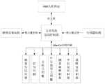
图2为本发明实施例一的装置控制关系示意图;2 is a schematic diagram of a device control relationship according to Embodiment 1 of the present invention;
图3为本发明实施例一的折弯伺服和去应力伺服的结构图;3 is a structural diagram of the bending servo and the stress relief servo according to the first embodiment of the present invention;
图4为本发明实施例一的方法流程图;FIG. 4 is a flow chart of the method according to Embodiment 1 of the present invention;
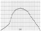
图5为本发明实施例一的步骤21中拟合的凸轮轨迹曲线;5 is a cam track curve fitted in
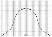
图6为本发明实施例一的步骤22中对称校正后的轨迹曲线;6 is a trajectory curve after symmetry correction in
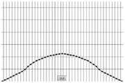
图7为本发明实施例一的步骤24中曲线平移前的轨迹曲线;Fig. 7 is the trajectory curve before curve translation in step 24 of the first embodiment of the present invention;
图8为本发明实施例一的步骤24中曲线平移后的轨迹曲线;FIG. 8 is a trajectory curve after the curve is shifted in step 24 of Embodiment 1 of the present invention;
图9为本发明实施例一的步骤25中曲线缩放前的轨迹曲线;Fig. 9 is the trajectory curve before curve scaling in step 25 of the first embodiment of the present invention;
图10为本发明实施例一的步骤25中曲线缩放后的轨迹曲线。FIG. 10 is a trajectory curve after curve scaling in step 25 of Embodiment 1 of the present invention.
附图标记说明:传动伺服1、折弯伺服2、凸轮一21、压块一22、去应力伺服3、凸轮二31、钢条4。Reference numeral description: transmission servo 1, bending servo 2, cam one 21, pressing block one 22, stress relief servo 3, cam two 31,
具体实施方式Detailed ways
以下通过特定的具体实例说明本发明的实施方式,本领域技术人员可由本说明书所揭露的内容轻易地了解本发明的其他优点与功效。本发明还可以通过另外不同的具体实施方式加以实施或应用,本说明书中的各项细节也可以基于不同观点与应用,在没有背离本发明的精神下进行各种修饰或改变。需说明的是,在不冲突的情况下,以下实施例及实施例中的特征可以相互组合。The embodiments of the present invention are described below through specific specific examples, and those skilled in the art can easily understand other advantages and effects of the present invention from the contents disclosed in this specification. The present invention can also be implemented or applied through other different specific embodiments, and various details in this specification can also be modified or changed based on different viewpoints and applications without departing from the spirit of the present invention. It should be noted that the following embodiments and features in the embodiments may be combined with each other under the condition of no conflict.
需要说明的是,以下实施例中所提供的图示仅以示意方式说明本发明的基本构想,遂图式中仅显示与本发明中有关的组件而非按照实际实施时的组件数目、形状及尺寸绘制,其实际实施时各组件的型态、数量及比例可为一种随意的改变,且其组件布局型态也可能更为复杂。It should be noted that the drawings provided in the following embodiments are only used to illustrate the basic concept of the present invention in a schematic way, so the drawings only show the components related to the present invention rather than the number, shape and number of components in actual implementation. For dimension drawing, the type, quantity and proportion of each component can be changed at will in actual implementation, and the component layout may also be more complicated.
实施例一:Example 1:
如图1、2所示,一种雨刮器钢条的折弯设备,包括主控系统、钢条放卷机构、传动伺服1、折弯伺服2、去应力伺服3、中位裁切伺服、钢条截断伺服、中位裁切传动装置以及钢条截断传动装置。其中中位裁切伺服设置于中位裁切传动装置,钢条截断伺服设置于钢条截断传动装置;传动伺服位于钢条放卷机构以及折弯伺服之间;去应力伺服位于折弯伺服与中位裁切伺服之间;中位裁切伺服位于去应力伺服与钢条截断伺服之间。主控系统分别与钢条放卷机构、传动伺服、折弯伺服、去应力伺服、中位裁切伺服、钢条截断伺服、中位裁切传动伺服以及钢条截断传动伺服通信连接。As shown in Figures 1 and 2, a bending equipment for wiper steel bars includes a main control system, a steel bar unwinding mechanism, a transmission servo 1, a bending servo 2, a stress relief servo 3, a mid-position cutting servo, and a steel Strip cutting servo, neutral cutting drive and steel strip cutting drive. The middle position cutting servo is set in the middle position cutting transmission device, the steel bar cutting servo is set in the steel bar cutting transmission device; the transmission servo is located between the steel strip unwinding mechanism and the bending servo; the stress relief servo is located between the bending servo and the bending servo. Between the middle cutting servo; the middle cutting servo is located between the stress relief servo and the steel bar truncation servo. The main control system is respectively connected with the steel strip unwinding mechanism, transmission servo, bending servo, stress relief servo, middle cutting servo, steel cutting servo, middle cutting transmission servo and steel cutting transmission servo.
所述主控系统包括运动控制器以及触摸屏,其中运动控制器用于控制伺服电机的转动方向和转动速度;触摸屏作为HMI人机界面,用于实现参数设置、功能控制、钢条折弯曲线调整以及配方存储等功能。其中运动控制器和钢条放卷机构之间通过数字量实现控制;运动控制器与HMI人机界面之间通过以太网实现信息的交互。The main control system includes a motion controller and a touch screen, wherein the motion controller is used to control the rotation direction and rotation speed of the servo motor; the touch screen, as an HMI human-machine interface, is used to realize parameter setting, function control, steel bar bending line adjustment and Recipe storage and other functions. Among them, the motion controller and the steel strip unwinding mechanism are controlled by digital quantity; the information exchange between the motion controller and the HMI man-machine interface is realized by Ethernet.
所述钢条放卷机构包括钢条放卷电机以及放卷检测传感器,其中放卷检测传感器能够检测钢条的传输速度,放卷电机的转速能够根据钢条的加工速度进行调节,实现自适应不同生产节拍的目的。The steel strip unwinding mechanism includes a steel strip unwinding motor and an unwinding detection sensor, wherein the unwinding detection sensor can detect the transmission speed of the steel strip, and the rotation speed of the unwinding motor can be adjusted according to the processing speed of the steel strip to achieve self-adaptation. The purpose of different production beats.
所述传动伺服1用于将钢条4传送至折弯伺服2的工作区域,其中传送的路径为直线传送。传动伺服1为EtherCat总线伺服。传动伺服1包括至少两组传动轮,每组传动轮包括两个传动轮;同一组传动轮组中的两个传动轮关于钢条4对称设置,并且位于钢条同一边的传动轮轴线的连线与钢条相平行。其目的是为了保证通过传动伺服的钢条保持平直。The transmission servo 1 is used to transmit the
如图3所示,所述折弯伺服2为EtherCat总线伺服,折弯伺服2采用绝对值型伺服电机作为驱动,折弯伺服还包括凸轮机构一,其中凸轮机构一通过模拟凸轮运动轨迹曲线实现控制,完成钢条的折弯操作。凸轮机构一包括凸轮一21和压块一22,其中压块一22相对凸轮一21的位置可以进行调节;钢条4位于压块一22和凸轮一21之间。在实施过程中,凸轮一21将钢条4压向压块一22,实现穿过凸轮一21和压块一22之间的钢条4的折弯操作。As shown in Figure 3, the bending servo 2 is an EtherCat bus servo, the bending servo 2 is driven by an absolute value servo motor, and the bending servo also includes a cam mechanism 1, wherein the cam mechanism 1 is realized by simulating the cam motion trajectory curve Control to complete the bending operation of the steel bar. The first cam mechanism includes a cam one 21 and a pressure block one 22, wherein the position of the pressure block one 22 relative to the cam one 21 can be adjusted; the
所述去应力伺服3为EtherCat总线伺服,去应力伺服3采用绝对值型伺服电机作为驱动,去应力伺服还包括凸轮机构二,其中凸轮机构二通过模拟凸轮运动轨迹曲线实现控制,在钢条经过折弯伺服折弯成型后,完成折弯应力的去除。凸轮机构二包括凸轮二31,凸轮二沿着设定的运动轨迹运动,对钢条4进行挤压,实现折弯应力的去除。其中凸轮二31的底部设置有滚轮,在本例中滚轮与完成折弯的钢条4的凸出一侧相接触,对钢条4进行挤压,释放折弯产生的应力。The stress-relieving servo 3 is an EtherCat bus servo, and the stress-relieving servo 3 is driven by an absolute value type servo motor. The stress-relieving servo also includes a second cam mechanism, wherein the second cam mechanism is controlled by simulating the cam motion trajectory curve. After the bending servo bending is formed, the removal of the bending stress is completed. The second cam mechanism includes a
所述中位裁切伺服为EtherCat总线伺服,中位裁切伺服用于在钢条的中间部位裁切安装孔位,其中安装孔位用于将钢条与雨刮器的其他部件进行安装连接。The mid-position cutting servo is an EtherCat bus servo, and the mid-position cutting servo is used to cut the installation holes in the middle of the steel strip, wherein the installation holes are used to install and connect the steel strip with other components of the wiper.
所述钢条截断伺服为EtherCat总线伺服,钢条截断伺服用于实现钢条的截断操作。The steel bar truncation servo is an EtherCat bus servo, and the steel bar truncation servo is used to realize the truncation operation of the steel bar.
所述中位裁切传动装置包括中位裁切传动伺服以及传动轨道一,中位裁切伺服设置于传动轨道一;钢条截断传动装置包括钢条截断传动伺服以及传动轨道二,钢条截断伺服设置于传动轨道二。在本例中中位裁切伺服能够随着中位裁切传动伺服的动作在传动轨道一上滑动,钢条截断伺服能够随着钢条截断传动伺服的动作在传动轨道二上滑动。其中中位裁切传动伺服以及钢条截断传动伺服均采用绝对值型伺服电机。The middle position cutting transmission device includes a middle position cutting transmission servo and a transmission track 1, and the middle position cutting servo is arranged on the first transmission track; The servo is arranged on the second transmission track. In this example, the middle position cutting servo can slide on the first transmission track with the action of the middle position cutting drive servo, and the steel bar cutting servo can slide on the second transmission track with the action of the steel bar cutting drive servo. Among them, the intermediate cutting drive servo and the steel bar cutting drive servo all use absolute value servo motors.
还包括原点检测传感器,其中原点检测传感器为零位检测开关,在本例中原点检测传感器分别设置于中位裁切伺服以及钢条截断伺服处,用于为中位裁切伺服以及钢条截断伺服提供定位检测,以实现精准的裁切或截断。其中原点检测传感器与主控系统的运动控制器之间通过数字量实现信息传递。It also includes an origin detection sensor, wherein the origin detection sensor is a zero detection switch. In this example, the origin detection sensor is respectively set at the middle cutting servo and the steel bar cutting servo, and is used for the middle cutting servo and steel bar cutting. Servo provides in-position detection for precise cuts or truncations. Among them, information is transmitted between the origin detection sensor and the motion controller of the main control system through digital quantities.
在实施的过程中,通过凸轮机构一实现钢条的折弯操作,同时在凸轮机构一与中位裁切伺服之间设置有凸轮机构二,通过凸轮机构二,消除钢条经过凸轮机构一产生的折弯应力;通过将中位裁切伺服设置于中位裁切传动装置,将钢条截断伺服设置于钢条截断传动装置,并且中位裁切伺服和钢条截断伺服能够分别在中位裁切传动装置的传动轨道一和钢条截断传动装置的传动轨道二上动作,精准控制裁切点和截断点,进而便于控制钢条的裁切长度,另一方面还能够减小钢条在裁切或截断时的晃动,保证钢条裁切和截断部位的准确。In the process of implementation, the bending operation of the steel bar is realized through the first cam mechanism, and the second cam mechanism is set between the first cam mechanism and the neutral cutting servo. The bending stress; by setting the mid-position cutting servo to the mid-position cutting transmission device, the steel bar cutting servo is set to the steel bar cutting transmission device, and the mid-position cutting servo and the steel bar-cutting servo can be respectively in the middle position. The driving track 1 of the cutting transmission device and the driving track 2 of the steel strip cutting transmission device act on the driving track, and the cutting point and the cutting point are precisely controlled, which is convenient to control the cutting length of the steel strip. Shaking during cutting or truncation ensures the accuracy of the cutting and truncation of the steel strip.
如图4所示,一种雨刮器钢条的折弯方法,包括如下步骤:As shown in Figure 4, a method for bending a wiper strip includes the following steps:
步骤1:运动控制器根据HMI人机界面的输入,下载钢条的加工配方;Step 1: The motion controller downloads the processing formula of the steel bar according to the input of the HMI human-machine interface;
步骤2:运动控制器根据HMI人机界面的输入对加工配方进行调节,包括对钢条数据的调节以及对电子凸轮参数的拟合调节,其中钢条数据包括截断长度、生产数量等,电子凸轮参数包括曲线偏移量、曲线平移、数据缩放以及曲线对称等数据;并将调节后的加工配方数据下发;Step 2: The motion controller adjusts the processing recipe according to the input of the HMI human-machine interface, including the adjustment of the steel bar data and the fitting adjustment of the parameters of the electronic cam, wherein the steel bar data includes the truncation length, production quantity, etc. The parameters include curve offset, curve translation, data scaling and curve symmetry; and the adjusted processing recipe data is issued;
步骤3:运动控制器控制中位裁切伺服与钢条截断伺服到指定位置;Step 3: The motion controller controls the median cutting servo and the steel bar cutting servo to the specified position;
步骤4:运动控制器控制钢条放卷机构与传动伺服开始动作,将钢条持续给进;Step 4: The motion controller controls the steel strip unwinding mechanism and the transmission servo to start action, and the steel strip is continuously fed;
步骤5:运动控制器控制折弯伺服以及去应力伺服根据拟合调节后的电子凸轮参数进行联动给进;Step 5: The motion controller controls the bending servo and the stress relief servo to perform linkage feeding according to the electronic cam parameters after fitting and adjustment;
步骤6:在传动伺服给进的钢条长度达到截断长度后,运动控制器控制中位裁切伺服以及钢条截断伺服动作;Step 6: After the length of the steel bar fed by the drive servo reaches the cutting length, the motion controller controls the middle position cutting servo and the steel bar cutting servo action;
步骤7:运动控制器判断钢条的生产数量是否已经满足输入的裁切数量需求;若少于输入的生产数量,则返回步骤4;否则,结束步骤。Step 7: The motion controller judges whether the production quantity of steel bars has met the input cutting quantity requirement; if it is less than the input production quantity, return to
所述步骤1中HMI人机界面的输入包括手动控制选项、参数设置、曲线设置、曲线配方保存与下载等。其中手动控制选项用于实现各个轴的点动控制(JOG),在设备调试时,通过控制各个轴的运动,便于实现设备的安装和调节。参数设置用于设置设备参数,包括各个伺服的运行速度等。曲线设置包括长尺寸和短尺寸两个模式,其中长尺寸和短尺寸根据钢条的实际截断长度进行判断;长尺寸模式的数据点相比短尺寸模式的数据点更多,因为长尺寸的钢条的折弯过程耗时更长,因此需要设置更多的数据点,以实现精准的控制。在本例中长尺寸模式将电子凸轮曲线模拟分解成63点数据,电子凸轮包括模拟凸轮一和模拟凸轮二,分别对应凸轮机构一和凸轮机构二的模拟状态;短尺寸模式将电子凸轮的轨迹曲线模拟分解成43点数据;通过将模拟凸轮一和模拟凸轮二的凸轮运动轨迹曲线进行划分,相比常规的简单控制凸轮运动距离的情况,根据凸轮的运动轨迹曲线对凸轮机构进行控制,能够实现更高精度,更平滑的折弯效果。曲线配方的保存与下载能够将对应钢条生产的最佳参数进行保存,并对保存的参数文件进行自定义命名;通过曲线配方的保存与下载能够节约重复或批量生产时,配置参数的时间。The input of the HMI man-machine interface in the step 1 includes manual control options, parameter settings, curve settings, curve formula saving and downloading, and the like. The manual control option is used to realize the jog control (JOG) of each axis. During equipment debugging, by controlling the movement of each axis, it is convenient to realize the installation and adjustment of the equipment. Parameter setting is used to set device parameters, including the running speed of each servo. The curve setting includes two modes: long size and short size, in which the long size and short size are judged according to the actual truncated length of the steel bar; the data points of the long size mode are more than those of the short size mode, because the long size steel The bar bending process takes longer, so more data points need to be set for precise control. In this example, the long-size mode decomposes the electronic cam curve simulation into 63 points of data. The electronic cam includes analog cam 1 and analog cam 2, which correspond to the simulation states of cam mechanism 1 and cam mechanism 2 respectively; short-size mode converts the trajectory of the electronic cam The curve simulation is decomposed into 43 points of data; by dividing the cam motion trajectory curves of the analog cam one and the analog cam two, compared with the conventional simple control of the cam motion distance, the cam mechanism is controlled according to the cam motion trajectory curve, which can Achieve higher precision and smoother bending results. The saving and downloading of the curve formula can save the best parameters corresponding to the production of steel bars, and the saved parameter file can be named by custom; the saving and downloading of the curve formula can save the time for parameter configuration during repeated or mass production.
所述步骤2电子凸轮参数的拟合调节包括如下步骤:The fitting adjustment of the electronic cam parameters in the step 2 includes the following steps:
步骤21:根据设定的拟合换算表拟合凸轮的轨迹曲线;Step 21: Fit the trajectory curve of the cam according to the set fitting conversion table;
步骤22:将完成拟合的凸轮曲线进行对称校正,通过设定前半部分的曲线设置,通过曲线对称功能,实现前半部分与后半部分对称设置;Step 22: Symmetrically correct the fitted cam curve, and realize the symmetrical setting of the first half and the second half by setting the curve setting of the first half and using the curve symmetry function;
步骤23:对曲线数据进行缓存备份;Step 23: Cache backup of curve data;
步骤24:对步骤22中完成对称校正的曲线数据进行曲线平移操作,通过曲线的左右平移进行曲线数据补偿,达到中点对称的效果;Step 24: perform a curve translation operation on the curve data that has been symmetrically corrected in
步骤25:对完成平移的曲线数据进行曲线缩放操作,将模拟凸轮一的运动轨迹曲线数据进行纵向放大或缩小,得到模拟凸轮二的运动轨迹曲线数据,实现整体数据的调整;Step 25: perform a curve scaling operation on the curve data that has completed the translation, and vertically enlarge or reduce the motion trajectory curve data of the simulated cam 1, obtain the motion trajectory curve data of the simulated cam 2, and realize the adjustment of the overall data;
步骤26:重新建立模拟凸轮一的凸轮轨迹曲线,并根据偏移量建立模拟凸轮二的凸轮轨迹曲线。Step 26: Re-establish the cam track curve of the simulated cam 1, and establish the cam track curve of the simulated cam 2 according to the offset.
如图5所示,所述步骤21中凸轮的轨迹曲线的横轴表示为主轴位置,即传动伺服给进钢条的虚拟长度,纵轴表示为电子凸轮的位置。其中拟合换算表包括43点拟合换算表以及63点拟合换算表,其中43点拟合换算表如表一所示,63点拟合换算表如表二所示:As shown in FIG. 5 , the horizontal axis of the trajectory curve of the cam in
表一43点凸轮曲线拟合换算表Table 1 43-point cam curve fitting conversion table


表二63点凸轮曲线拟合换算表Table 2 63-point cam curve fitting conversion table


其中表一和表二中的速度和加速度均为纵轴方向上的向量,即与钢条给进方向相垂直的方向。The velocity and acceleration in Table 1 and Table 2 are all vectors in the direction of the longitudinal axis, that is, the direction perpendicular to the feeding direction of the steel bar.
如图6所示,所述步骤22中对拟合曲线进行对称校正,实现前半部分与后半部分对称设置,大大提高用户调节效率。其中电子凸轮的凸轮轨迹曲线的对称校正公式如下式所示:As shown in FIG. 6 , in the
若模拟凸轮一的凸轮轨迹曲线通过43个点数据进行划分,即钢条的长度设置为短尺寸,其中:If the cam track curve of the simulated cam 1 is divided by 43 point data, that is, the length of the steel bar is set to the short dimension, where:
TF[(43-n+1)]=TF[n]M=0时;n>=1;TF[(43-n+1)]=TF[n] when M=0; n>=1;
TF[(43-n+1)]=TF[n+2M]M>0,M<=5时;n>=2;TF[(43-n+1)]=TF[n+2M] when M>0, M<=5; n>=2;
TF[(43-n+1)+2M]=TF[n]M<0,M>=-5时;n>=2;TF[(43-n+1)+2M]=TF[n] when M<0, M>=-5; n>=2;
其中n表示曲线点数,TF[n]表示在模拟凸轮一的轨迹曲线中第n个曲线点对应的纵坐标值;M表示平移参数,需要说明的是,在本实施例中曲线的平移在曲线的对称校正之后进行,此时M为0,在一些其他实施方式中也可以先进行曲线的平移操作,随后再进行曲线的对称校正。Among them, n represents the number of curve points, TF[n] represents the ordinate value corresponding to the nth curve point in the trajectory curve of the simulated cam 1; M represents the translation parameter. It should be noted that in this embodiment, the translation of the curve is in the curve After the symmetry correction of , M is 0 at this time. In some other embodiments, the curve translation operation may be performed first, and then the curve symmetry correction is performed.
若模拟凸轮一的的凸轮轨迹曲线通过63个点数据进行划分,即钢条的长度设置为长尺寸,其中:If the cam track curve of the simulated cam 1 is divided by 63 point data, that is, the length of the steel bar is set to the long dimension, where:
TF[(63-n+1)]=TF[n]M=0时;n>=1;TF[(63-n+1)]=TF[n] when M=0; n>=1;
TF[(63-n+1)]=TF[n+2M]M>0,M<=5时;n>=2;TF[(63-n+1)]=TF[n+2M] when M>0, M<=5; n>=2;
TF[(63-n+1)+2M]=TF[n]M<0,M>=-5时;n>=2;TF[(63-n+1)+2M]=TF[n] when M<0, M>=-5; n>=2;
其中n表示曲线点数,TF[n]表示在模拟凸轮一的轨迹曲线中第n个曲线点位置的纵坐标值;M表示平移参数。Among them, n represents the number of curve points, TF[n] represents the ordinate value of the nth curve point position in the trajectory curve of simulated cam 1; M represents the translation parameter.
如图7、8所示,所述步骤24中曲线平移操作,如下式所示:As shown in Figures 7 and 8, the curve translation operation in step 24 is shown in the following formula:
TF[n]=Copy_TF[n-M]n-M>0且n>=2;TF[n]=Copy_TF[n-M]n-M>0 and n>=2;
其中M表示平移参数;TF[n]表示模拟凸轮一的轨迹曲线中第n个曲线点的纵坐标值,在本例中为步骤22中对称校正后第n个曲线点的纵坐标值;Copy_TF[n-M]表示模拟凸轮一在步骤23中缓存备份数据的第n-M个点的缓存备份数组。where M represents the translation parameter; TF[n] represents the ordinate value of the nth curve point in the trajectory curve of the simulated cam 1, in this example, the ordinate value of the nth curve point after the symmetry correction in
如图9、10所示,所述步骤25中,曲线缩放的公式如下:As shown in Figures 9 and 10, in step 25, the formula for curve scaling is as follows:
TW[n]=TF[n]*s;TW[n]=TF[n]*s;
其中TF[n]表示模拟凸轮一的轨迹曲线中第n个曲线点所处位置的纵坐标值;TW[n]表示模拟凸轮二的轨迹曲线中第n个曲线点所处位置的纵坐标值;s表示缩放比例。其中若选择短尺寸,则1<=n<=43;若选择长尺寸,则1<=n<=63。TF[n] represents the ordinate value of the position of the nth curve point in the trajectory curve of the simulated cam 1; TW[n] represents the ordinate value of the position of the nth curve point in the trajectory curve of the simulated cam 2 ; s is the scaling factor. Among them, if the short size is selected, then 1<=n<=43; if the long size is selected, then 1<=n<=63.
所述步骤26中重新建立凸轮曲线,需要将实际折弯伺服与凸轮表拟合曲线建立的关系,进行换算和数据转换。其中43点短尺寸中将线段均匀划分为39段,第20条线段为中位线段,中位线段包括4条小线段;同样的,63点长尺寸中将线段均匀划分为59段,其第30条线段作为中位线段,中位线段包括4条小线段;通过划分中位线段包括小线段,使钢条在中间的折弯部位加工时,凸轮的运动轨迹能够更加准确,实现折弯部分的平滑过渡。以短尺寸为例,根据表一可知设置模拟凸轮一的主轴虚拟行程长度为29250,其中每个曲线点对应的主轴给进量表示为P,P=29250/39,主轴表示传动伺服,主轴虚拟行程长度表示传动伺服给进钢条的长度;主轴的缩放参数K表示为K=L/29250,其中L表示步骤2中设定的钢条截断长度,缩放参数K表示实际的主轴给进钢条的长度,即实际截断长度与模拟的主轴虚拟行程长度之间的倍数关系。主轴位置如下式所示:To re-establish the cam curve in the step 26, it is necessary to perform conversion and data conversion on the relationship established between the actual bending servo and the cam table fitting curve. In the 43-point short dimension, the line segment is evenly divided into 39 segments, the 20th line segment is the median line segment, and the median line segment includes 4 small line segments; similarly, in the 63-point long dimension, the line segment is evenly divided into 59 segments. 30 line segments are used as the median line segment, and the median line segment includes 4 small line segments; by dividing the median line segment including the small line segments, when the steel bar is processed in the middle bending part, the movement trajectory of the cam can be more accurate, and the bending part can be realized. smooth transition. Taking the short size as an example, according to Table 1, it can be seen that the virtual stroke length of the spindle of the analog cam 1 is set to 29250, in which the spindle feed corresponding to each curve point is expressed as P, P=29250/39, the spindle represents the transmission servo, and the spindle virtual The stroke length represents the length of the steel bar fed by the drive servo; the scaling parameter K of the spindle is expressed as K=L/29250, where L represents the cut-off length of the steel bar set in step 2, and the scaling parameter K represents the actual spindle fed steel bar The length of , that is, the multiple relationship between the actual truncation length and the simulated virtual stroke length of the spindle. The spindle position is as follows:
ZD[n]=P*(n-1); 1<=n<=20;ZD[n]=P*(n-1); 1<=n<=20;
ZD[n]=P*19+(P/4)*(n-20); 21<=n<=23;ZD[n]=P*19+(P/4)*(n-20); 21<=n<=23;
ZD[n]=P*(n-4); 24<=n<=43;ZD[n]=P*(n-4); 24<=n<=43;
其中ZD[n]表示主轴给进钢条第n个曲线点到模拟凸轮一时主轴的给进长度,在模拟凸轮一的轨迹曲线中表示为第n个曲线点对应的横坐标;Among them, ZD[n] represents the feed length of the spindle from the nth curve point of the spindle feeding the steel bar to the simulation cam 1, which is expressed as the abscissa corresponding to the nth curve point in the trajectory curve of the simulated cam 1;
模拟凸轮一位置如下式所示:The analog cam-1 position is shown in the following formula:
CD[n]=TF[n];1<=n<=43;CD[n]=TF[n]; 1<=n<=43;
其中CD[n]表示钢条给进到第n个曲线点时对应的模拟凸轮一的位置;Where CD[n] represents the corresponding simulated cam 1 position when the steel bar is fed to the nth curve point;
模拟凸轮一的联动速度如下式所示:The linkage speed of analog cam 1 is shown in the following formula:
V[n]=(CD[n]-CD[n-1])/P; 2<=n<=20且24<=n<=43;V[n]=(CD[n]-CD[n-1])/P; 2<=n<=20 and 24<=n<=43;
V[n]=(CD[n]-CD[n-1])/(P/4); 21<=n<=23;V[n]=(CD[n]-CD[n-1])/(P/4); 21<=n<=23;
V[1]=V[2]; n=1;V[1]=V[2]; n=1;
其中V[n]表示在模拟凸轮一的轨迹曲线中第n个曲线点时在纵轴方向上的速度。Wherein V[n] represents the velocity in the direction of the vertical axis at the nth curve point in the trajectory curve of the simulated cam 1.
同样的,根据表一可知设置的模拟凸轮二对应的主轴虚拟行程长度也为29250,因此主轴的每点位移量P表示为P=29250/39;主轴的缩放参数K表示为K=L/29250,其中L表示步骤2中设定的钢条的截断长度;实际平移量微调为E,换算后的平移量微调为e,e=E/K,需要说明的是平移量微调是对曲线平移补偿量。主轴位置如下式所示:Similarly, according to Table 1, it can be seen that the virtual stroke length of the main shaft corresponding to the analog cam 2 is also 29250, so the displacement P of each point of the main shaft is expressed as P=29250/39; the scaling parameter K of the main shaft is expressed as K=L/29250 , where L represents the cut-off length of the steel bar set in step 2; the actual translation fine-tuning is E, the converted translation fine-tuning is e, e=E/K, it should be noted that the translation fine-tuning is compensation for the curve translation quantity. The spindle position is as follows:
ZDX[n]=P*(n-1); 1<=n<=(1+2M);ZDX[n]=P*(n-1); 1<=n<=(1+2M);
ZDX[n]=P*(n-1)+e; (1+2M)<n<=(20+M);ZDX[n]=P*(n-1)+e; (1+2M)<n<=(20+M);
ZDX[n]=P*(20+M)+(P/4)*(n-20); (21+M)<=n<=(23+M);ZDX[n]=P*(20+M)+(P/4)*(n-20); (21+M)<=n<=(23+M);
ZDX[n]=P*(n-4)+e; (24+M)<=n<=43;ZDX[n]=P*(n-4)+e; (24+M)<=n<=43;
其中ZDX[n]表示模拟凸轮二在第n个曲线点时主轴对应的给进长度,在模拟凸轮二的钢条轨迹曲线中表示为第n个曲线点的横坐标;Among them, ZDX[n] represents the feed length of the spindle corresponding to the nth curve point of the simulated cam 2, and it is represented as the abscissa of the nth curve point in the steel bar trajectory curve of the simulated cam 2;
模拟凸轮二位置如下式所示:The second position of the analog cam is shown in the following formula:
CDX[n]=TW[n]+g;1<=n<=43;CDX[n]=TW[n]+g; 1<=n<=43;
其中CDX[n]表示模拟凸轮二的轨迹曲线中第n个曲线点对应的模拟凸轮二的位置;g表示模拟凸轮一和模拟凸轮二之间的位置偏移量,即模拟凸轮一和模拟凸轮二的间隔距离;Where CDX[n] represents the position of the analog cam 2 corresponding to the nth curve point in the trajectory curve of the analog cam 2; g represents the position offset between the analog cam 1 and the analog cam 2, that is, the analog cam 1 and the analog cam The separation distance of two;
模拟凸轮二的联动速度如下式所示:The linkage speed of analog cam 2 is shown in the following formula:
VX[n]=(CD[n]-CD[n-1])/P; 2<=n<=(20+M)且(24+M)<=n<=43;VX[n]=(CD[n]-CD[n-1])/P; 2<=n<=(20+M) and (24+M)<=n<=43;
VX[n]=(CD[n]-CD[n-1])/(P/4); (21+M)<=n<=(23+M);VX[n]=(CD[n]-CD[n-1])/(P/4); (21+M)<=n<=(23+M);
VX[1]=VX[2]; n=1;VX[1]=VX[2]; n=1;
其中VX[n]表示在模拟凸轮二轨迹曲线的第n个曲线点时的纵轴方向上的速度。Wherein VX[n] represents the velocity in the direction of the vertical axis when simulating the nth curve point of the two-track cam curve.
所述步骤7中钢条的生产数量根据中位裁切伺服或者钢条截断伺服的动作次数进行判断,其中钢条的生产数量为w,中位裁切伺服或者钢条截断伺服的动作次数为v,w=v-1。在实施的过程中,中位裁切伺服与钢条截断伺服第一次动作,实现钢条a1一端的截断和钢条a1中部的裁切打孔;中位裁切伺服与钢条截断伺服第二次动作,实现钢条a1和钢条a2的分离以及钢条a2中部的裁切打孔,因此经过v次动作后能够获得w条钢条。In the step 7, the production quantity of the steel bar is judged according to the number of actions of the middle position cutting servo or the steel bar truncation servo, wherein the production quantity of the steel bar is w, and the number of actions of the middle position cutting servo or the steel bar truncation servo is: v, w=v-1. During the implementation process, the middle position cutting servo and the steel bar truncation servo act for the first time to realize the truncation of one end of the steel bar a1 and the cutting and punching of the middle of the steel bar a1; the middle position cutting servo and the steel bar truncation servo are the first The second action realizes the separation of the steel bar a1 and the steel bar a2 and the cutting and punching of the middle of the steel bar a2. Therefore, the w bar can be obtained after v operations.
在实施的过程中,通过设置两个模拟的电子凸轮,同步操控凸轮机构一和凸轮机构二,实现钢条折弯的去应力操作,提高产品的稳定性和使用寿命;另一方面,设置电子凸轮进行模拟,便于调试机器,能够提高产品的调试效率;通过对电子凸轮参数进行拟合调节,包括对称校正、曲线平移以及曲线缩放等操作,实现更好的钢条折弯效果。In the process of implementation, two simulated electronic cams are set, and the cam mechanism 1 and cam mechanism 2 are synchronously controlled to realize the stress relief operation of the steel bar bending and improve the stability and service life of the product; on the other hand, set the electronic The cam is simulated, which is convenient for debugging the machine and can improve the debugging efficiency of the product; by fitting and adjusting the parameters of the electronic cam, including the operations of symmetry correction, curve translation and curve scaling, a better steel bar bending effect can be achieved.
以上描述仅是本发明的一个具体实例,不构成对本发明的任何限制。显然对于本领域的专业人员来说,在了解了本发明内容和原理后,都可能在不背离本发明原理、结构的情况下,进行形式和细节上的各种修改和改变,但是这些基于本发明思想的修正和改变仍在本发明的权利要求保护范围之内。The above description is only a specific example of the present invention, and does not constitute any limitation to the present invention. Obviously, for those skilled in the art, after understanding the content and principles of the present invention, various modifications and changes in form and details may be made without departing from the principles and structures of the present invention, but these are based on the present invention. Modifications and changes of the inventive idea still fall within the protection scope of the claims of the present invention.
Claims (9)


Priority Applications (3)
| Application Number | Priority Date | Filing Date | Title |
|---|---|---|---|
| CN202210936680.2ACN115283507B (en) | 2021-03-16 | 2021-03-16 | A method for bending a wiper steel bar |
| CN202210936834.8ACN115283508B (en) | 2021-03-16 | 2021-03-16 | A windshield wiper steel bar bending device |
| CN202110282054.1ACN113059040B (en) | 2021-03-16 | 2021-03-16 | A kind of bending equipment and method of wiper steel strip |
Applications Claiming Priority (1)
| Application Number | Priority Date | Filing Date | Title |
|---|---|---|---|
| CN202110282054.1ACN113059040B (en) | 2021-03-16 | 2021-03-16 | A kind of bending equipment and method of wiper steel strip |
Related Child Applications (2)
| Application Number | Title | Priority Date | Filing Date |
|---|---|---|---|
| CN202210936834.8ADivisionCN115283508B (en) | 2021-03-16 | 2021-03-16 | A windshield wiper steel bar bending device |
| CN202210936680.2ADivisionCN115283507B (en) | 2021-03-16 | 2021-03-16 | A method for bending a wiper steel bar |
Publications (2)
| Publication Number | Publication Date |
|---|---|
| CN113059040A CN113059040A (en) | 2021-07-02 |
| CN113059040Btrue CN113059040B (en) | 2022-10-04 |
Family
ID=76560627
Family Applications (3)
| Application Number | Title | Priority Date | Filing Date |
|---|---|---|---|
| CN202110282054.1AActiveCN113059040B (en) | 2021-03-16 | 2021-03-16 | A kind of bending equipment and method of wiper steel strip |
| CN202210936680.2AActiveCN115283507B (en) | 2021-03-16 | 2021-03-16 | A method for bending a wiper steel bar |
| CN202210936834.8AActiveCN115283508B (en) | 2021-03-16 | 2021-03-16 | A windshield wiper steel bar bending device |
Family Applications After (2)
| Application Number | Title | Priority Date | Filing Date |
|---|---|---|---|
| CN202210936680.2AActiveCN115283507B (en) | 2021-03-16 | 2021-03-16 | A method for bending a wiper steel bar |
| CN202210936834.8AActiveCN115283508B (en) | 2021-03-16 | 2021-03-16 | A windshield wiper steel bar bending device |
Country Status (1)
| Country | Link |
|---|---|
| CN (3) | CN113059040B (en) |
Cited By (1)
| Publication number | Priority date | Publication date | Assignee | Title |
|---|---|---|---|---|
| CN115283508A (en)* | 2021-03-16 | 2022-11-04 | 浙江大学台州研究院 | Bending equipment for wiper steel bars |
Citations (2)
| Publication number | Priority date | Publication date | Assignee | Title |
|---|---|---|---|---|
| WO2014063262A1 (en)* | 2012-10-22 | 2014-05-01 | Güdel Group AG | Method for the determination of workpiece transport trajectories in a multiple station press |
| CN106217433A (en)* | 2016-07-19 | 2016-12-14 | 杭州朝阳橡胶有限公司 | A kind of tyre surface cut-to-length method |
Family Cites Families (17)
| Publication number | Priority date | Publication date | Assignee | Title |
|---|---|---|---|---|
| AT233618B (en)* | 1960-03-07 | 1964-05-25 | Plasser Bahnbaumasch Franz | Equipment on mobile machines for aligning the track |
| US5005135A (en)* | 1989-03-22 | 1991-04-02 | Cincinnati Milacron, Inc. | Dynamic correction of servo following errors in a computer-numerically controlled system and fixed cycle utilizing same |
| DE102005040263A1 (en)* | 2005-08-24 | 2007-03-01 | Müller Weingarten AG | Method and device for controlling and regulating the slide movement on servo-electric presses |
| KR20120046947A (en)* | 2010-11-03 | 2012-05-11 | 주식회사 우진정공 | Bus bar banding device |
| CN202622049U (en)* | 2012-06-02 | 2012-12-26 | 深圳市威科达科技有限公司 | Integrated fly-shearing servo driving device |
| CN102716953A (en)* | 2012-06-21 | 2012-10-10 | 陕西科技大学 | Cam type variable-curvature pipe bending system and method |
| DE102012110661B4 (en)* | 2012-11-07 | 2014-06-26 | Progress-Werk Oberkirch Ag | Curved rail for a transfer system and forming machine |
| CN103736835A (en)* | 2013-07-04 | 2014-04-23 | 天津格润科农冷弯有限公司 | Greenhouse water tank framework on-line cold roll forming technology |
| CN203281675U (en)* | 2013-08-05 | 2013-11-13 | 游本俊 | Bending device of heat pipe bending machine |
| CN104646449A (en)* | 2013-11-16 | 2015-05-27 | 无锡大金高精度冷拔钢管有限公司 | Manufacturing method for cold drawn welded pipe used for hydraulic oil cylinders |
| CN204108099U (en)* | 2014-10-14 | 2015-01-21 | 江苏省南扬机械制造有限公司 | A kind of process units of T-shaped lamp profile |
| CN104772407A (en)* | 2015-03-26 | 2015-07-15 | 金陵科技学院 | Control system based on numerical-control wire bending robot |
| CN206046794U (en)* | 2016-08-24 | 2017-03-29 | 东莞大市自动化科技有限公司 | A kind of full-automatic molding numerical control bender |
| CN207138565U (en)* | 2017-07-12 | 2018-03-27 | 施秀清 | A kind of servo digital control bender for bus-bar |
| CN108750653B (en)* | 2018-07-17 | 2024-02-27 | 陕西科技大学 | Control method of multi-track electronic cam picking and placing manipulator |
| CN209379689U (en)* | 2018-10-17 | 2019-09-13 | 高鹏 | Numerical control servo drives cam-type straightener |
| CN113059040B (en)* | 2021-03-16 | 2022-10-04 | 浙江大学台州研究院 | A kind of bending equipment and method of wiper steel strip |
- 2021
- 2021-03-16CNCN202110282054.1Apatent/CN113059040B/enactiveActive
- 2021-03-16CNCN202210936680.2Apatent/CN115283507B/enactiveActive
- 2021-03-16CNCN202210936834.8Apatent/CN115283508B/enactiveActive
Patent Citations (2)
| Publication number | Priority date | Publication date | Assignee | Title |
|---|---|---|---|---|
| WO2014063262A1 (en)* | 2012-10-22 | 2014-05-01 | Güdel Group AG | Method for the determination of workpiece transport trajectories in a multiple station press |
| CN106217433A (en)* | 2016-07-19 | 2016-12-14 | 杭州朝阳橡胶有限公司 | A kind of tyre surface cut-to-length method |
Cited By (2)
| Publication number | Priority date | Publication date | Assignee | Title |
|---|---|---|---|---|
| CN115283508A (en)* | 2021-03-16 | 2022-11-04 | 浙江大学台州研究院 | Bending equipment for wiper steel bars |
| CN115283508B (en)* | 2021-03-16 | 2025-08-29 | 浙江大学台州研究院 | A windshield wiper steel bar bending device |
Also Published As
| Publication number | Publication date |
|---|---|
| CN115283508A (en) | 2022-11-04 |
| CN115283508B (en) | 2025-08-29 |
| CN113059040A (en) | 2021-07-02 |
| CN115283507A (en) | 2022-11-04 |
| CN115283507B (en) | 2025-05-09 |
Similar Documents
| Publication | Publication Date | Title |
|---|---|---|
| CN113059040B (en) | A kind of bending equipment and method of wiper steel strip | |
| CN103135498B (en) | A kind of numerically-controlled machine contour machining radius error compensating control method and device | |
| CN106738046B (en) | The asynchronous die-cutting apparatus of Unequal distance and method | |
| CN206437058U (en) | A kind of new double-front-axle steering | |
| CN101032731A (en) | Flying shears with high speed and definite length | |
| CN209062245U (en) | Medium plate shearing production line | |
| CN201105306Y (en) | New high-speed CNC spring machine | |
| CN207982128U (en) | A CNC feeding mechanism for a metal punching machine | |
| CN101596569B (en) | Spring processing device and method | |
| CN205291085U (en) | Control system of biax corrugated paper peeler based on electron cam | |
| CN201419224Y (en) | Spring processing device | |
| CN205271877U (en) | Nib rigging equipment with industry camera | |
| CN111414672B (en) | Crankshaft grinding method and device based on numerical control system | |
| CN204448952U (en) | Hydraulic pressure hollow pipe fitting springback control device | |
| CN209176011U (en) | A kind of automatic trimming equipment for calender | |
| CN204374726U (en) | A kind of digital control system based on B-spline curves high speed real-time interpolation | |
| CN212400418U (en) | Main transmission structure of large-scale multi-station mechanical press | |
| CN205736092U (en) | Adjustable skin carving pressing mold forming machine | |
| CN2705239Y (en) | Sizing composite device of composite coating machine | |
| CN214242710U (en) | Transfer chain goods changes to mechanism | |
| CN202570926U (en) | Synchronous and asynchronous spinning machine with two spinning rollers | |
| CN109514168B (en) | Stainless steel pipe welding method | |
| CN202803539U (en) | Gap adjusting devices for precise coating head device | |
| CN103170546B (en) | A kind of longeron bending positioner | |
| CN114226515B (en) | Forming processing method for swing arm of windscreen wiper |
Legal Events
| Date | Code | Title | Description |
|---|---|---|---|
| PB01 | Publication | ||
| PB01 | Publication | ||
| SE01 | Entry into force of request for substantive examination | ||
| SE01 | Entry into force of request for substantive examination | ||
| GR01 | Patent grant | ||
| GR01 | Patent grant |