CN113055047B - Low power long range radio - Google Patents
Low power long range radioDownload PDFInfo
- Publication number
- CN113055047B CN113055047BCN202011435525.XACN202011435525ACN113055047BCN 113055047 BCN113055047 BCN 113055047BCN 202011435525 ACN202011435525 ACN 202011435525ACN 113055047 BCN113055047 BCN 113055047B
- Authority
- CN
- China
- Prior art keywords
- symbols
- symbol
- chirp
- radio
- modulation
- Prior art date
- Legal status (The legal status is an assumption and is not a legal conclusion. Google has not performed a legal analysis and makes no representation as to the accuracy of the status listed.)
- Active
Links
Images


Classifications
- H—ELECTRICITY
- H04—ELECTRIC COMMUNICATION TECHNIQUE
- H04L—TRANSMISSION OF DIGITAL INFORMATION, e.g. TELEGRAPHIC COMMUNICATION
- H04L1/00—Arrangements for detecting or preventing errors in the information received
- H04L1/08—Arrangements for detecting or preventing errors in the information received by repeating transmission, e.g. Verdan system
- H—ELECTRICITY
- H04—ELECTRIC COMMUNICATION TECHNIQUE
- H04B—TRANSMISSION
- H04B1/00—Details of transmission systems, not covered by a single one of groups H04B3/00 - H04B13/00; Details of transmission systems not characterised by the medium used for transmission
- H04B1/69—Spread spectrum techniques
- H—ELECTRICITY
- H04—ELECTRIC COMMUNICATION TECHNIQUE
- H04B—TRANSMISSION
- H04B1/00—Details of transmission systems, not covered by a single one of groups H04B3/00 - H04B13/00; Details of transmission systems not characterised by the medium used for transmission
- H04B1/02—Transmitters
- H04B1/04—Circuits
- H—ELECTRICITY
- H04—ELECTRIC COMMUNICATION TECHNIQUE
- H04B—TRANSMISSION
- H04B1/00—Details of transmission systems, not covered by a single one of groups H04B3/00 - H04B13/00; Details of transmission systems not characterised by the medium used for transmission
- H04B1/69—Spread spectrum techniques
- H04B1/707—Spread spectrum techniques using direct sequence modulation
- H04B1/7073—Synchronisation aspects
- H04B1/7085—Synchronisation aspects using a code tracking loop, e.g. a delay-locked loop
- H—ELECTRICITY
- H04—ELECTRIC COMMUNICATION TECHNIQUE
- H04B—TRANSMISSION
- H04B1/00—Details of transmission systems, not covered by a single one of groups H04B3/00 - H04B13/00; Details of transmission systems not characterised by the medium used for transmission
- H04B1/69—Spread spectrum techniques
- H04B1/707—Spread spectrum techniques using direct sequence modulation
- H04B1/7073—Synchronisation aspects
- H04B1/7087—Carrier synchronisation aspects
- H—ELECTRICITY
- H04—ELECTRIC COMMUNICATION TECHNIQUE
- H04L—TRANSMISSION OF DIGITAL INFORMATION, e.g. TELEGRAPHIC COMMUNICATION
- H04L1/00—Arrangements for detecting or preventing errors in the information received
- H04L1/004—Arrangements for detecting or preventing errors in the information received by using forward error control
- H04L1/0041—Arrangements at the transmitter end
- H—ELECTRICITY
- H04—ELECTRIC COMMUNICATION TECHNIQUE
- H04L—TRANSMISSION OF DIGITAL INFORMATION, e.g. TELEGRAPHIC COMMUNICATION
- H04L1/00—Arrangements for detecting or preventing errors in the information received
- H04L1/004—Arrangements for detecting or preventing errors in the information received by using forward error control
- H04L1/0056—Systems characterized by the type of code used
- H04L1/0071—Use of interleaving
- H—ELECTRICITY
- H04—ELECTRIC COMMUNICATION TECHNIQUE
- H04L—TRANSMISSION OF DIGITAL INFORMATION, e.g. TELEGRAPHIC COMMUNICATION
- H04L27/00—Modulated-carrier systems
- H04L27/10—Frequency-modulated carrier systems, i.e. using frequency-shift keying
- H04L27/103—Chirp modulation
- H—ELECTRICITY
- H04—ELECTRIC COMMUNICATION TECHNIQUE
- H04L—TRANSMISSION OF DIGITAL INFORMATION, e.g. TELEGRAPHIC COMMUNICATION
- H04L27/00—Modulated-carrier systems
- H04L27/18—Phase-modulated carrier systems, i.e. using phase-shift keying
- H04L27/20—Modulator circuits; Transmitter circuits
- H04L27/2032—Modulator circuits; Transmitter circuits for discrete phase modulation, e.g. in which the phase of the carrier is modulated in a nominally instantaneous manner
- H04L27/2053—Modulator circuits; Transmitter circuits for discrete phase modulation, e.g. in which the phase of the carrier is modulated in a nominally instantaneous manner using more than one carrier, e.g. carriers with different phases
- H04L27/206—Modulator circuits; Transmitter circuits for discrete phase modulation, e.g. in which the phase of the carrier is modulated in a nominally instantaneous manner using more than one carrier, e.g. carriers with different phases using a pair of orthogonal carriers, e.g. quadrature carriers
- H04L27/2067—Modulator circuits; Transmitter circuits for discrete phase modulation, e.g. in which the phase of the carrier is modulated in a nominally instantaneous manner using more than one carrier, e.g. carriers with different phases using a pair of orthogonal carriers, e.g. quadrature carriers with more than two phase states
- H04L27/2071—Modulator circuits; Transmitter circuits for discrete phase modulation, e.g. in which the phase of the carrier is modulated in a nominally instantaneous manner using more than one carrier, e.g. carriers with different phases using a pair of orthogonal carriers, e.g. quadrature carriers with more than two phase states in which the data are represented by the carrier phase, e.g. systems with differential coding
- H—ELECTRICITY
- H04—ELECTRIC COMMUNICATION TECHNIQUE
- H04L—TRANSMISSION OF DIGITAL INFORMATION, e.g. TELEGRAPHIC COMMUNICATION
- H04L7/00—Arrangements for synchronising receiver with transmitter
- H04L7/04—Speed or phase control by synchronisation signals
- H04L7/048—Speed or phase control by synchronisation signals using the properties of error detecting or error correcting codes, e.g. parity as synchronisation signal
- H—ELECTRICITY
- H04—ELECTRIC COMMUNICATION TECHNIQUE
- H04L—TRANSMISSION OF DIGITAL INFORMATION, e.g. TELEGRAPHIC COMMUNICATION
- H04L7/00—Arrangements for synchronising receiver with transmitter
- H04L7/04—Speed or phase control by synchronisation signals
- H04L7/08—Speed or phase control by synchronisation signals the synchronisation signals recurring cyclically
- H—ELECTRICITY
- H04—ELECTRIC COMMUNICATION TECHNIQUE
- H04B—TRANSMISSION
- H04B1/00—Details of transmission systems, not covered by a single one of groups H04B3/00 - H04B13/00; Details of transmission systems not characterised by the medium used for transmission
- H04B1/02—Transmitters
- H04B1/04—Circuits
- H04B2001/0491—Circuits with frequency synthesizers, frequency converters or modulators
- H—ELECTRICITY
- H04—ELECTRIC COMMUNICATION TECHNIQUE
- H04B—TRANSMISSION
- H04B1/00—Details of transmission systems, not covered by a single one of groups H04B3/00 - H04B13/00; Details of transmission systems not characterised by the medium used for transmission
- H04B1/69—Spread spectrum techniques
- H04B2001/6912—Spread spectrum techniques using chirp
Landscapes
- Engineering & Computer Science (AREA)
- Computer Networks & Wireless Communication (AREA)
- Signal Processing (AREA)
- Digital Transmission Methods That Use Modulated Carrier Waves (AREA)
- Control Of Eletrric Generators (AREA)
- Electroluminescent Light Sources (AREA)
Abstract
Description
Translated fromChinese技术领域technical field
本发明在实施例中涉及长程低功率无线电发射器和接收器,例如用于数字合成啁啾扩频信号的无线电发射器和接收器。The present invention relates in embodiments to long range low power radio transmitters and receivers, such as radio transmitters and receivers for digitally synthesizing chirped spread spectrum signals.
背景技术Background technique
欧洲专利申请EP2449690描述了一种使用数字合成啁啾符号作为调制的通信系统,以及适当的基于FFT的接收器。European patent application EP2449690 describes a communication system using digitally synthesized chirp symbols as modulation, and a suitable FFT-based receiver.
除了别的以外,欧洲专利申请EP2763321还描述了一种这样的调制方法,其中信号的相位是基本上毗连的,以及啁啾以使得允许发射器与接收器节点之间的同步并且确定它们之间的传播范围的方式被嵌入数据帧中。这个调制方案用于Semtech公司的长程LoRaTMRF技术中,并且在本文档的以下内容中将简单地称作‘LoRa’。European patent application EP2763321 describes, among other things, such a modulation method in which the phases of the signals are substantially contiguous and chirped so as to allow synchronization between the transmitter and receiver nodes and to determine the The way the spread range is embedded in the data frame. This modulation scheme is used in Semtech's long-range LoRa™ RF technology and will be referred to simply as 'LoRa' throughout the remainder of this document.
EP3264622公开了一种适合于物联网应用的低复杂度 LoRa接收器。EP3264622 discloses a low-complexity LoRa receiver suitable for IoT applications.
LoRa调制能够容许高误差率,只要它们是静态或者缓慢漂移的。但是,频率误差的快速变化可导致同步问题,所述同步问题最终导致解调误差。本发明提供一种能够克服这个缺点的增强调制器。LoRa modulations can tolerate high error rates as long as they are static or slowly drifting. However, rapid changes in frequency error can cause synchronization problems, which ultimately lead to demodulation errors. The present invention provides an enhanced modulator which overcomes this disadvantage.
发明内容Contents of the invention
根据本发明,这些目标通过所附权利要求书的对象来实现。特别是,这些目标通过具有发射部分的低功率长程无线电装置来实现,该低功率长程无线电装置包括:编码器,其在操作上布置用于将数字消息编码为具有多个位的符号;接收符号的调制器,其布置用于合成一系列解调啁啾,所述一系列解调啁啾的瞬时频率按照作为一个基础啁啾函数的循环移位的多个函数之一而改变,其中啁啾的循环移位表示对应符号的值;包括差分编码单元,该差分编码单元接收编码器所生成的一系列符号作为输入,并且生成一系列差分编码符号作为输出,由此输入符号的每个可能值对应于所述一系列差分编码符号的预定变化。According to the invention, these objects are achieved by the objects of the appended claims. In particular, these objects are achieved by a low-power long-range radio having a transmitting part comprising: an encoder operatively arranged to encode a digital message into symbols having a plurality of bits; receiving symbols A modulator arranged to synthesize a series of demodulation chirps whose instantaneous frequency varies according to one of a plurality of functions that are a cyclic shift of a function of an underlying chirp, wherein the chirp The cyclic shift of represents the value of the corresponding symbol; includes a differential encoding unit that receives as input a sequence of symbols generated by the encoder and produces as output a sequence of differentially encoded symbols whereby each possible value of the input symbol corresponds to a predetermined change in the series of differentially encoded symbols.
从属权利要求介绍尽管是有利的但并不是必不可少的其他技术特征,例如:数字消息的处理,其由交织器、格雷编码器并且由差分编码单元来处理;可能对每个帧中的差分编码单元没有处理的例如检测和同步部分来选择性禁用能够被有选择地禁用的差分编码单元;接收部分包括用于获取所接收的啁啾信号的循环移位的去啁啾单元,之后接着软差分解码器;符号重复,布置成采用通过预定的一连串循环移位(所述预定的一连串循环移位能够包括零移位)从输入符号得出的预定数量的符号来取代输入符号。The dependent claims introduce other technical features which, although advantageous, are not essential, such as: processing of digital messages by interleaver, Gray coder and by differential coding unit; The encoding unit does not handle such as the detection and synchronization part to selectively disable the differential encoding unit that can be selectively disabled; the receiving part includes a de-chirp unit for obtaining a cyclic shift of the received chirped signal, followed by a soft A differential decoder; symbol repetition, arranged to replace input symbols with a predetermined number of symbols derived from the input symbols by a predetermined series of cyclic shifts, which can include a zero shift.
本发明的独立方面涉及一种具有发射部分的低功率长程无线电装置,所述低功率长程无线电装置包括:编码器,其在操作上布置用于将数字消息编码为具有多个位的符号;接收符号的调制器,布置用于合成一系列调制啁啾,所述一系列调制啁啾的瞬时频率按照作为一个基础啁啾函数的循环移位的多个函数之一而改变,其中啁啾的循环移位表示对应符号的值;包括符号重复单元,该符号重复单元在操作上布置成采用通过预定的一连串循环移位(所述预定的一连串循环移位能够包括零移位)从输入符号得出的预定数量的符号来取代输入符号。An independent aspect of the invention relates to a low power long range radio having a transmitting part, said low power long range radio comprising: an encoder operatively arranged to encode a digital message into a symbol having a plurality of bits; a receiving A modulator of symbols arranged to synthesize a series of modulated chirps the instantaneous frequency of which varies according to one of a plurality of functions that are a cyclic shift of a function of the underlying chirp, wherein the cyclic of the chirps The shift represents the value of the corresponding symbol; comprising a symbol repetition unit operatively arranged to use A predetermined number of symbols to replace the input symbols.
附图说明Description of drawings
借助于作为举例所给出并且通过附图所示的实施例的描述,将会更好地了解本发明,在附图中:The invention will be better understood with the aid of the description of an embodiment given by way of example and shown in the accompanying drawings, in which:
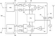
图1按照示意简化方式示出根据本发明的一个方面的无线电调制解调器的结构。FIG. 1 shows the structure of a radio modem according to one aspect of the invention in a schematically simplified manner.
图2a绘制根据本发明的一个方面的基础啁啾和调制啁啾的瞬时频率。相同信号的相位在图2b中表示,以及图2c绘制时域中的基础啁啾的实分量和复分量。Figure 2a plots the instantaneous frequency of the fundamental chirp and the modulated chirp according to one aspect of the invention. The phase of the same signal is represented in Fig. 2b, and Fig. 2c plots the real and complex components of the underlying chirp in the time domain.
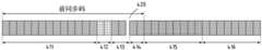
图3示意表示在本发明的框架中的两个装置之间所交换的数据帧的结构。FIG. 3 schematically shows the structure of a data frame exchanged between two devices within the framework of the invention.
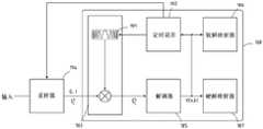
图4示出LoRa解调器的可能结构。Figure 4 shows a possible structure of a LoRa demodulator.
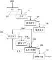
图5示出根据本发明的一个方面的具有差分编码方案的调制器。Figure 5 illustrates a modulator with a differential encoding scheme according to one aspect of the present invention.
图6和图7示出两个可能的简化调制集合。Figures 6 and 7 show two possible simplified modulation sets.
图8示出具有差分编码方案的调制器。Figure 8 shows a modulator with a differential encoding scheme.
具体实施方式detailed description
本发明中采用的啁啾调制技术的若干方面在欧洲专利 EP3264622中描述(这通过引用被结合于此),并且将在这里简要提醒。图1中示意表示的无线电收发器是本发明的可能实施例。收发器包括基带部分200和射频部分100。发射器包括基带调制器150,该基带调制器150在其输入处基于数字数据152来生成基带复合信号。这然后由RF部分100来转换成预期传输频率,由功率放大器120来放大,并且由天线来传输。Several aspects of the chirp modulation technique employed in the present invention are described in European Patent EP3264622 (which is hereby incorporated by reference) and will be briefly reminded here. The radio transceiver schematically represented in Figure 1 is a possible embodiment of the invention. The transceiver includes a
一旦信号在无线电链路的另一端被接收,则它由图1的收发器的接收部分来处理,所述接收部分包括低噪声放大器160,之后是下变频级170,然后由基带处理器180来处理,该下变频级170生成包含一系列啁啾的基带信号(该基带信号也是例如通过两个分量I、 Q所表示的复合信号),基带处理器180的功能与调制器150的功能相反,并且提供重构数字信号182。Once the signal is received at the other end of the radio link, it is processed by the receive section of the transceiver of FIG. processing, the down-
如EP3264622所讨论的,待处理信号包括一系列啁啾,一系列啁啾的频率沿预定时间间隔从初始瞬时值f0改变成最终瞬时频率 f1。为了简化描述,将假定全部啁啾具有相同持续时间T,但是这不是对本发明的绝对要求。As discussed in EP3264622, the signal to be processed comprises a series of chirps whose frequency changes from an initial instantaneous valuef0 to a final instantaneous frequency f1 along predetermined time intervals. To simplify the description, it will be assumed that all chirps have the same duration T, but this is not an absolute requirement of the invention.
基带信号中的啁啾能够通过其瞬时频率的时间分布f(t)或者还通过函数φ(t)来描述,函数φ(t)定义将信号的相位定义为时间的函数,如图2a-2b所绘制。重要地,处理器180被布置成处理和识别具有多个不同分布的啁啾,每个分布对应于预定调制字母表中的符号。The chirp in the baseband signal can be described by the time distribution f(t) of its instantaneous frequency or also by the function φ(t), which defines the phase of the signal as a function of time, as shown in Figure 2a-2b drawn. Importantly, the
图2c是时域中的与基础啁啾对应的基带信号的实和虚分量I、Q的图。Figure 2c is a diagram of the real and imaginary components I, Q of the baseband signal corresponding to the fundamental chirp in the time domain.
信号还可包括共轭啁啾,即,作为基本未调制啁啾的复共轭的啁啾。能够将这些看作是向下啁啾(down-chirp),其中频率从 f0=-BW/2的值下降到f1=BW/2。The signal may also comprise a conjugate chirp, ie a chirp that is the complex conjugate of the basic unmodulated chirp. These can be seen as down-chirps, where the frequency drops from a value of f0 =-BW/2 to f1 =BW/2.
按照本发明的重要特征,接收信号Rx能够包括具有特定和预定义频率分布的基础啁啾(下面又称作未调制啁啾)或者通过对基础频率分布的循环时移而从基础啁啾得到的可能调制啁啾集合中的啁啾。图2a作为举例示出啁啾开始的时刻t=t0与啁啾结束的时刻t=t1之间的一个调制啁啾和基础啁啾的可能频率和相位分布,而图2b示出时域中的对应基带信号。水平标度例如对应于符号,以及虽然曲线被绘制为连续的,但是它们实际上表示具体实现中的有限数量的离散采样。至于垂直标度,它们被归一化成预计带宽或者归一化成对应的相位跨度。相位在图2b中表示为好像它是有界变量,以便更好地表明其连续性,但是它实际上在具体实现中可跨越若干周期(revolution)。According to an important feature of the invention, the received signal Rx can comprise a fundamental chirp (hereinafter also referred to as an unmodulated chirp) with a specific and predefined frequency distribution or derived from the fundamental chirp by a cyclic time shift of the fundamental frequency distribution. It is possible to modulate the chirps in the set of chirps. Figure 2a shows by way of example possible frequency and phase distributions of a modulated chirp and a fundamental chirp between the chirp start instant t = t0 and the chirp end instant t = t1 , while Figure 2b shows the time domain The corresponding baseband signal in . The horizontal scale corresponds to symbols, for example, and although the curves are drawn as continuous, they actually represent a finite number of discrete samples in a specific implementation. As for the vertical scales, they are normalized to the expected bandwidth or to the corresponding phase span. The phase is represented in Fig. 2b as if it were a bounded variable to better show its continuity, but it can actually span several revolutions in a specific implementation.
我们采用N来表示符号的长度或者等效地表示扩展因子。为了允许使用FFT的容易的接收,N优选地被选择为二的幂。尼奎斯特采样频率为1/BW,以及符号的长度为N/BW。为了确定概念而不是将本发明限制到这些具体数值,能够设想,在可能应用中,BW为 1MHz,以及N等于1024、512或256。载波频率可处于2.45GHz IMS 频段中。在这个实施例中,本发明的调制方案可占用与

因此,调制符号是基本符号的循环移位,该调制符号是0 与N-1之间的任何数,其中N=2SF,SF是扩展因子。0的调制值等同于没有调制。由于N是二的幂,所以每个调制啁啾因此能够被看作是对其循环移位中可以编码的log2N个比特进行编码的符号。有时有利的是,将符号星座限制为简化集合,所述简化集合是为了本公开的目的而被定义为可能符号的适当子集。Therefore, the modulation symbol is a cyclic shift of the basic symbol, and the modulation symbol is any number between 0 and N-1, where N=2SF , and SF is the spreading factor. A modulation value of 0 is equivalent to no modulation. Since N is a power of two, each modulation chirp can thus be viewed as a symbol encoding the log2 N bits that can be encoded in its cyclic shift. It is sometimes advantageous to restrict symbol constellations to a reduced set defined for the purposes of this disclosure as an appropriate subset of possible symbols.
因此,“循环移位值”在下文中可用来指示时域中的调制,而“调制位置”或“峰值位置”表示频域中的调制。Hence, "cyclic shift value" may be used hereinafter to indicate modulation in the time domain, while "modulation position" or "peak position" indicates modulation in the frequency domain.
在所示示例中,基础啁啾的频率从初始值f0=-BW/2线性增加到最终值f1=BW/2,其中BW代表带宽扩展,但是下降啁啾或其他啁啾分布也是可能的。因此,信息采取具有相对于预定基础啁啾的多个可能循环移位中的一个循环移位的啁啾的形式来编码,每个循环移位对应于可能调制符号,或者,以其他方式说,处理器180需要处理包含多个频率啁啾(所述多个频率啁啾是基础啁啾分布的循环时移复制品)的信号,并且提取在一系列所述时移中编码的消息。In the example shown, the frequency of the base chirp increases linearly from an initial value f0 = -BW/2 to a final value f1 =BW/2, where BW stands for bandwidth extension, but falling chirps or other chirp distributions are also possible of. Information is thus encoded in the form of a chirp having one of a plurality of possible cyclic shifts relative to a predetermined base chirp, each cyclic shift corresponding to a possible modulation symbol, or, in other words,
优选地,通过本发明所传输和接收的信号按照适当编码的帧(所述帧包括前同步码和数据段)来组织。前同步码和数据段包括一系列调制和/或未调制的啁啾,所述啁啾允许接收器将其时间参考与发射器的时间参考进行时间对齐,检索信息元素,执行动作,或者执行命令。在本发明的帧中,若干结构对于数据帧是可能的,这除了其他以外还取决于信道条件、所传输数据或命令。图3示意表示本发明的各个方面中能够采用的帧结构。帧可在前同步码中包括一系列检测符号411,所述检测符号411允许对接收器中的传入信号、同步符号 412、413和414的不同编组、报头415以及有效载荷416(该有效载荷416包括预计给目标节点并且可具有可变长度的消息)的检测。Preferably, signals transmitted and received by the present invention are organized in suitably coded frames comprising preamble and data segments. The preamble and data segments consist of a series of modulated and/or unmodulated chirps that allow the receiver to time align its time reference with the transmitter's time reference, retrieve information elements, perform actions, or execute commands . In the frame of the invention, several structures are possible for the data frame, depending among others on the channel conditions, transmitted data or commands. Fig. 3 schematically shows a frame structure that can be employed in various aspects of the present invention. A frame may include a series of
解调demodulation
优选地,啁啾的相位通过连续函数φ(t)来描述,该连续函数φ(t)在啁啾的开始和结束具有相同值:φ(t0)=φ(t1)。因此,信号的相位跨符号边界是连续的,下面将称作符号间相位连续性的特征。在图 2a所示的示例中,函数f(t)是对称的,并且信号具有符号间相位连续性。如EP2449690更详细解释的,上述信号的结构允许接收器中的处理器180将其时间参考与发射器的时间参考对齐,以及循环移位量的确定被赋予每个啁啾。Preferably, the phase of the chirp is described by a continuous function φ(t) having the same value at the beginning and end of the chirp: φ(t0 )=φ(t1 ). Thus, the phase of the signal is continuous across symbol boundaries, which will hereinafter be referred to as a feature of inter-symbol phase continuity. In the example shown in Figure 2a, the function f(t) is symmetric and the signal has inter-symbol phase continuity. As explained in more detail in EP2449690, the structure of the above signal allows the
评估所接收的啁啾相对本地时间参考的时移的操作在下文中可称作“去啁啾”,并且能够通过解扩步骤(该去解扩步骤涉及将所接收的啁啾与本地生成的基础啁啾的复共轭相乘)和解调步骤(该解调步骤在于执行解扩信号的FFT)有利地执行。但是,去啁啾的其他方式是可能的。The operation of evaluating the time shift of the received chirp with respect to a local time reference may hereinafter be referred to as "de-chirping" and can be performed by a despreading step which involves combining the received chirp with a locally generated base Complex conjugate multiplication of chirps) and a demodulation step consisting in performing an FFT of the despread signal) are advantageously performed. However, other ways of de-chirping are possible.
我们采用


解扩和解调的这些操作分别在如图4所示的基带处理器 180的解扩单元183、相应地解调单元185中实现。采样单元194在基带处理器之前,该采样单元194按照任何适当方式来生成一系列采样
在所示示例中,帧具有前同步码,该前同步码包括基本(即,未调制或者具有等于零的循环移位)符号的检测序列411。检测序列 411在接收器中用来检测信号的开始,以及优选地用来执行其时间参考与发射器中的时间参考的第一同步。符号412、413和414的编组是LoRa协议所要求的,并且用于同步,但是不一定是本发明的组成部分。前同步码之后可接着是消息报头415(该消息报头415通知接收器关于后续数据的格式)和有效载荷416(该有效载荷416通过应用来定义)。通过对检测序列进行解调,接收器能够确定移位量,并且采用发送方的时钟频率和相位来适配其时钟的频率和相位,从而允许对之后数据的解码。In the example shown, the frame has a preamble comprising a
由于LoRa调制使用同一基本波形的循环移位,所以解调误差在大多数情况下为±1移位单位的误差或者在极少情况下为±2移位单位的误差。优选地,本发明的调制器包括差分编码单元,该差分编码单元被布置用于生成一系列移位,其中输入符号的每个可能值对应于一系列差分编码符号的预定变化。图5示出对应调制链的可能实现:必须传输的数字流由插入适当纠错码的前向纠错单元205来处理,然后由交织器207和格雷映射器216来处理。框219将经格雷编码的值变换为期望的调制字母表(又称作调制集合)。字母表可以是完整或简化的。Since LoRa modulation uses a cyclic shift of the same basic waveform, the demodulation error is in most cases an error of ±1 shift unit or in rare cases an error of ±2 shift units. Preferably, the modulator of the present invention comprises a differential encoding unit arranged to generate a sequence of shifts, wherein each possible value of the input symbol corresponds to a predetermined variation of the sequence of differentially encoded symbols. FIG. 5 shows a possible implementation of the corresponding modulation chain: the digital stream that has to be transmitted is processed by a forward
完整调制集合包括与此处从0至2SF-1的可能循环移位同样多的符号。有噪条件中的误差率能够减小,尽管伴随带宽减小,从而选择未包括全部可能符号的简化调制集合。图6示出选择简化调制集合的可能方式,该简化调制集合仅包括范围0、...2SF-1中的形式K·p的符号,其中p表示整数,以及K是倍增因数,例如K=4。K应当是符号长度的除数;如果符号长度为二的幂,则K也应当是这样的。这确保在差分编码中进行的积分和模量运算之后,调制集合未改变。The complete modulation set includes as many symbols as there are possible cyclic shifts from 0 to 2SF -1. The error rate in noisy conditions can be reduced, albeit with reduced bandwidth, choosing a simplified modulation set that does not include all possible symbols. Fig. 6 shows a possible way of choosing a reduced modulation set comprising only symbols of the form K p in the
框225和228符号化差分编码中涉及的操作。前者225是数值积分器,该数值积分器累加单元219所生成的循环移位,以及框 228实现模量运算,该模量运算生成0、...2SF-1中的差分码238。
选择/控制框230允许也在帧内的正常与差分码之间的任意切换。优选地,采用非差分调制来传输前同步码,而报头和有效载荷可以经过差分编码或者可以不经过差分编码。在便利布置中,报头未经差分编码,并且发信号通知关于有效载荷是否经过差分编码。以此方式,全部接收器(无论这些接收器是否能够接收差分调制)都能够对报头解码并且理解报头。在这个布置中,接收器无需预先了解使用哪一种调制格式。选择框230按照是期望正常调制还是差分调制来向啁啾合成器232发送或者正常循环移位235或者差分编码移位238。它还在必要时(例如在正常与差分码之间转变时)重置积分器225。A selection/
在接收时,差分调制通常与大约3dB的损耗关联,因为第一解调操作通常是具有独立噪声贡献的两个符号之间的差。这种情况能够通过特殊软解码器来减轻。On reception, differential modulation is typically associated with a loss of about 3dB, since the first demodulation operation is typically the difference between two symbols with independent noise contributions. This situation can be mitigated by special soft decoders.
软输出差分解调器考虑当前符号与前一个符号之间的潜在调制值对。对于每个位,独立于其他位,将具有与‘0’值对应的最大合计幅度的对与具有与‘1’值对应的最大合计幅度的对进行比较。为了将复杂度降低到实际水平,对每个符号仅比较一些调制值,它们对应于FFT之后显示最高幅度的调制值。A soft-output differential demodulator considers potential pairs of modulation values between the current symbol and the previous symbol. For each bit, the pair with the largest aggregate magnitude corresponding to a '0' value is compared to the pair with the largest aggregate magnitude corresponding to a '1' value, independently of the other bits. In order to reduce the complexity to a practical level, only some modulation values are compared for each symbol, which correspond to the modulation values showing the highest amplitude after FFT.
我们引入下列标记法:We introduce the following notation:
·nmax代表按照每个符号所考虑的潜在调制值的数量nmax represents the number of potential modulation values considered per symbol
·m是当前符号的索引,以及m-1代表前一个符号的索引m is the index of the current symbol, and m-1 represents the index of the previous symbol
·{Am,l}(其中1的范围从0至nmax-1)代表对于符号m在FFT 之后的最大幅值的列表。我们进一步假定它们按照 Am,0>Am,1>Am,2>Am...来排序• {Am, l } (where 1 ranges from 0 to nmax -1) represents a list of maximum magnitudes after FFT for symbol m. We further assume that they are sorted by Am, 0 > Am, 1 > Am, 2 > Am ...
·{Mm,i}(其中i的范围从0至nmax-1)是与集合{Am,1}对应的调制值。在FFT输出处,{Mm,i}是索引,以及{Am,1}是幅值。• {Mm,i } (where i ranges from 0 to nmax -1) is the modulation value corresponding to the set {Am,1 }. At the FFT output, {Mm, i } is the index, and {Am, 1 } is the magnitude.
·HD(x)是解映射函数(HD代表硬解码)这是格雷映射的逆函数,其之后接着索引缩放。HD(x)的输出是位集合,并且我们将采用HDj(x) 来表示位j的输出。索引j的范围从0至log2(调制集合)-1• HD(x) is the demapping function (HD stands for hard decoding) which is the inverse of Gray mapping followed by index scaling. The output of HD(x) is a set of bits, and we will denote the output of bit j by HDj (x). The index j ranges from 0 to log2 (modulation set)-1
在符号m,对于每个位j,我们计算:In symbol m, for each bit j, we compute:
S0,j:(i,k)的集合,使得HDj(Mm,k-Mm-1,i)=0S0,j : set of (i,k) such that HDj (Mm,k -Mm-1,i )=0
(注意:HD函数包括mod(2SF)运算,以涵盖其中调制差为负的情况)(Note: the HD function includes a mod(2SF ) operation to cover the case where the modulation difference is negative)
S1,j:(i,k)的集合,使得HDj(Mm,k-Mm-1,i)=1S1,j : set of (i,k) such that HDj (Mm,k -Mm-1,i )=1
S0,j是(i,k)的集合,使得在符号(m-1)的调制值Mm-1,i以及在符号(k) 的调制值Mm,k的传输暗示位j对于符号m具有值0。相反,S1,j是集合,使得位j对于相同传输具有值1。任何对(i,k)属于S0,j或者属于S1,j。S0,j is the set of (i,k) such that the transmission of the modulation value Mm-1,i at symbol (m-1) and the modulation value Mm,k at symbol (k) implies that bit j for symbol m has a value of 0. Conversely, S1,j is the set such that bit j has
然后我们计算:Then we calculate:


最后,在符号m的位j的软解调输出被计算为SDj=AA1,j-AA0,j。Finally, the soft-demodulated output at bit j of symbol m is calculated as SDj =AA1,j -AA0,j .
所公开的软差分解调方法对每个符号m考虑有限数量的可能调制值,以及对每个位考虑当前符号中和前一个符号中的调制值的可能对。该方法按照那个位的所产生的值将调制值的可能对编组在两个集合中。软解调值被计算为两个集合中的最大合计幅值的差。发明人已经发现,与非差分软解调相比,这样的软解调方法对于典型噪声水平和等效误差率给出1dB的噪声增加。所考虑调制值的数量保持为适度地低,8是典型数字。The disclosed soft differential demodulation method considers for each symbol m a finite number of possible modulation values, and for each bit a possible pair of modulation values in the current symbol and in the previous symbol. The method groups possible pairs of modulation values in two sets according to the resulting value of that bit. The soft demodulation value is calculated as the difference of the largest summed magnitudes in the two sets. The inventors have found that such a soft demodulation method gives a 1 dB noise increase for typical noise levels and equivalent error rates compared to non-differential soft demodulation. The number of modulation values considered is kept moderately low, 8 being a typical number.
与上面公开的差分调制和解调方法相组合或者作为其替代,能够在不增大符号长度的情况下通过重复符号来增加灵敏度。接近极限灵敏度,当前通过检测和同步跟踪来确定系统的极限。前一限制可通过延长前同步码来解决。但是,同步产生接收消息中的不能通过FEC来恢复的误差。In combination with or as an alternative to the differential modulation and demodulation methods disclosed above, sensitivity can be increased by repeating symbols without increasing the symbol length. Approaching limit sensitivity, detection and simultaneous tracking are currently used to determine the limits of the system. The former limitation can be solved by extending the preamble. However, synchronization produces errors in received messages that cannot be recovered by FEC.
本发明的调制器可在传输帧中插入符号的重复,以准许接收器中的误差的检测和校正。重复可以是相同的或者优选地是根据对接收器为已知的或者能够由接收器所计算的循环移位而进行的移位符号的重复。LoRa调制字母表使用0与2SF-1之间的循环移位的规则分布。对于关系到对噪声和跟踪的什么程度的抗性,一些调制值,例如接近符号长度的一半的那些调制值,比其他的调制值要弱。符号重复中引入的移位可平衡这些较弱值的分布。例如,如果重复水平为2 (即,每个符号被传输二次),则一个传输可被系统地按 symbol_length/2移位。如果重复水平为4,则移位可以是{0, symbol_length/4,symbol_length/2,symbol_length/4}等等。The modulator of the present invention can insert repetitions of symbols in the transmission frame to permit detection and correction of errors in the receiver. The repetition may be the same or preferably a repetition of the shifted symbols according to a cyclic shift known to the receiver or capable of being calculated by the receiver. The LoRa modulation alphabet uses a regular distribution of cyclic shifts between 0 and 2SF -1. Some modulation values, such as those close to half the symbol length, are weaker than others as far as resistance to noise and tracking is concerned. The shift introduced in symbol repetition balances the distribution of these weaker values. For example, if the repetition level is 2 (ie, each symbol is transmitted twice), then one transmission can be systematically shifted by symbol_length/2. If the repetition level is 4, the shifts can be {0, symbol_length/4, symbol_length/2, symbol_length/4} and so on.
格雷编码在检测和校正跟踪误差中是有用的,由于LoRa 中的循环移位的使用,导致最常见误差是其中符号被接收并且被解调为从原始值移位±1的值的那些误差。在格雷解映射之后,这类误差转化为任意位误差。Gray coding is useful in detecting and correcting tracking errors, due to the use of cyclic shifts in LoRa, the most common errors are those where symbols are received and demodulated to values shifted by ±1 from the original values. After Gray demapping, such errors are transformed into arbitrary bit errors.
差分调制具有与格雷编码相似的目的,但是它以不同方式处理误差:稳态误差(在接收器侧处的定时或频率的长恒定误差)在第一次出现之后不重复;采用格雷编码的过渡符号-其中误差首次出现或结束-具有随机位误差。在快速变化信道中,这导致高误差率。Differential modulation has a similar purpose to Gray coding, but it handles errors differently: steady-state errors (long constant errors in timing or frequency at the receiver side) do not repeat after the first occurrence; transitions with Gray coding Symbols - where the error first appears or ends - have random bit errors. In fast changing channels this leads to high error rates.
简化调制集合能够帮助这些高要求情况,尽管以带宽为代价。格雷编码可能不是必需的。Simplifying the modulation set can help in these demanding cases, albeit at the expense of bandwidth. Gray encoding may not be necessary.
图6示出其中使用四个符号中的一个符号的调制集合的简化的简单方案。本示例涉及SF6调制,使得可能符号的范围从0至63 或者按照二进制的1111。仅使用形式4·p的符号,而从未被生成的其他符号通过“N/A”来指示。图6仅示出可能的64个调制值的四分之一。Figure 6 shows a simplified simple scheme in which a modulation set of one out of four symbols is used. This example involves SF6 modulation such that possible symbols range from 0 to 63 or 1111 in binary. Only symbols of the
图7示出调制集合的简化的另一种方案,该方案有利地结合差分调制,其中误差不是整数的采样或者傅立叶域中的整数的FFT 窗口(FFT bin)。与图6的映射函数相比,新映射函数每符号传输附加位(或者附加位字段)。附加位通过B1来表示,而其余SF-2位通过Bh来表示。在二的编组中仅使用符号的一半,而从不使用其余一半,但是其他方案是可能的。与4·p简化方案相比,存在一位的有效增加。Fig. 7 shows another scheme of simplification of the modulation set, which advantageously incorporates differential modulation, where the error is not an integer number of samples or an integer number of FFT bins in the Fourier domain. Compared to the mapping function of Figure 6, the new mapping function transmits additional bits (or additional bit fields) per symbol. Additional bits are represented by B1, while the remaining SF-2 bits are represented by Bh. Only half of the symbols are used in groupings of two and the other half is never used, but other schemes are possible. There is an effective increase of one bit compared to the 4·p reduction scheme.
由于使用差分调制,所以解调中的恒定偏移将不会影响 Bh位,也不会影响B1位。简化方案布置成使得位的Bb字段是“高可靠性”字段,所述“高可靠性”字段是当所感知循环移位中存在±1的误差时也能够可靠和正确地被解码的,例如因为简化方案按照对Bh的相同值进行编码的编组来组织。B1位是“低可靠性”字段,并且受到这类过渡所影响。Since differential modulation is used, a constant offset in demodulation will not affect the Bh bit, nor the B1 bit. The simplified scheme is arranged such that theB field of bits is a "high reliability" field that can be reliably and correctly decoded even when there is an error of ±1 in the perceived cyclic shift, e.g. Because the simplified scheme is organized in groups that encode the same value ofBh . The B1 bit is a "low reliability" field and is affected by such transitions.
图8按照示意形式示出实现上述替代的映射的调制链的可能实现。包括框205、207、216、219的右分支对应于以上相对图5 所公开的处理器,并且其输出仍然是可用的。右分支包括分离操作201,其中消息被分为两个单独的流,一个对应于(SF-2)位,以及一个对应于一位。数据优选地已通过纠错码的插入(框265)和交织(267) 来独立处理。有利地,Bh分支的前向纠错方案以及B1分支的前向纠错方案是不同的,并且在两个分支中的不同编码速率的功能中被优化。框289在积分225之前对Bh和B1的组合进行符号化。Figure 8 shows in schematic form a possible implementation of a modulation chain implementing the above alternative mapping. The right
因此,控制单元230具有在三个可能数据流之间的选择来传输:没有差分编码或平行映射的常规数据D(m);差分编码数据;以及采用附加B1位的简化集合中的经编码的数据,其经过差分编码。Thus, the
参考标号reference number
100 RF级100 RF class
102 RF开关102 RF switch
110 混合器110 mixer
120 功率放大器120 power amplifier
129 本地振荡器129 local oscillator
150 调制器150 modulators
152 用于传输的数据152 Data for transmission
154 缓冲器154 buffers
160 低噪声放大器160 Low Noise Amplifier
170 混合器170 mixer
180 解调器180 demodulator
182 接收的数据182 Received data
183 解扩单元183 despreading unit
185 解调器185 demodulator
186 软解映射器186 soft demapper
187 硬解映射器187 Hard Demapper
191 复制啁啾191 Copy Chirp
192 定时误差跟踪192 Timing Error Tracking
194 采样器194 samplers
200 基带处理器200 baseband processor
201 分离201 Separation
205 纠错205 error correction
207 交织器207 interleaver
216 格雷映射216 gray map
219 缩放219 Zoom
225 积分器225 Integrator
228 模量包装(modulo wrapping)228 Modulo wrapping
230 选择/控制230 Choice/Control
232 啁啾合成232 Chirp Synthesis
235 非差分编码移位235 non-differential code shift
238 差分编码移位238 differential code shift
265 纠错265 error correction
267 交织器267 interleaver
189 平行映射189 parallel mapping
411 检测序列411 detection sequence
412 帧同步符号412 frame sync symbol
413 频率同步符号413 Frequency Synchronization Symbol
414 精细同步符号414 fine synchronization symbols
415 报头415 header
416 有效载荷416 payload
420 寂静420 silence
Claims (10)
Translated fromChineseApplications Claiming Priority (2)
| Application Number | Priority Date | Filing Date | Title |
|---|---|---|---|
| EP19215072.0 | 2019-12-11 | ||
| EP19215072.0AEP3836409B1 (en) | 2019-12-11 | 2019-12-11 | Low power long-range radio |
Publications (2)
| Publication Number | Publication Date |
|---|---|
| CN113055047A CN113055047A (en) | 2021-06-29 |
| CN113055047Btrue CN113055047B (en) | 2023-01-13 |
Family
ID=68848185
Family Applications (1)
| Application Number | Title | Priority Date | Filing Date |
|---|---|---|---|
| CN202011435525.XAActiveCN113055047B (en) | 2019-12-11 | 2020-12-10 | Low power long range radio |
Country Status (4)
| Country | Link |
|---|---|
| US (1) | US11245434B2 (en) |
| EP (1) | EP3836409B1 (en) |
| KR (1) | KR102444378B1 (en) |
| CN (1) | CN113055047B (en) |
Families Citing this family (6)
| Publication number | Priority date | Publication date | Assignee | Title |
|---|---|---|---|---|
| EP3836409B1 (en)* | 2019-12-11 | 2025-05-07 | Semtech Corporation | Low power long-range radio |
| US12301276B2 (en) | 2021-02-05 | 2025-05-13 | Texas Instruments Incorporated | Frequency-division multiplexing |
| CN114301495B (en)* | 2021-12-10 | 2023-05-19 | 河南工程学院 | A soft output demodulation method under non-coherent LoRa system |
| EP4293922A1 (en)* | 2022-06-17 | 2023-12-20 | Semtech Corporation | Transmitter, receiver, and method for chirp-modulated radio signals |
| CN115733899B (en)* | 2022-10-18 | 2024-12-20 | 香港理工大学深圳研究院 | Message generation and parsing method for parallel modulation of LoRa CSS signals |
| CN116389208B (en)* | 2023-03-10 | 2025-07-01 | 中国电子科技集团公司第三十八研究所 | A skew-shift keying-Chirp modulation and demodulation method |
Family Cites Families (17)
| Publication number | Priority date | Publication date | Assignee | Title |
|---|---|---|---|---|
| US7430257B1 (en)* | 1998-02-12 | 2008-09-30 | Lot 41 Acquisition Foundation, Llc | Multicarrier sub-layer for direct sequence channel and multiple-access coding |
| US6940893B1 (en)* | 1999-09-27 | 2005-09-06 | Telecommunications Research Laboratories | High-speed indoor wireless chirp spread spectrum data link |
| CN1213552C (en)* | 2002-07-10 | 2005-08-03 | 华为技术有限公司 | Return-to-zero code super long distance transmission method and equipment |
| KR100654009B1 (en)* | 2002-08-22 | 2006-12-04 | 아이트란 커뮤니케이션스 리미티드 | Spread Spectrum Communication System Using Differential Code Shift Keying |
| US20070110140A1 (en)* | 2005-11-14 | 2007-05-17 | Ipwireless, Inc. | Automatic selection of coherent and noncoherent transmission in a wireless communication system |
| EP2278724A1 (en) | 2009-07-02 | 2011-01-26 | Nanoscale Labs | Communications system |
| CN101793960B (en)* | 2009-10-27 | 2013-12-11 | 北京邮电大学 | High-accuracy dynamic threshold target monitoring method with chirping characteristics |
| GB2494146B (en)* | 2011-08-31 | 2018-05-09 | Qualcomm Technologies Int Ltd | Chirp communications |
| EP2763321B1 (en) | 2013-02-05 | 2020-04-08 | Semtech Corporation | Low power long range transmitter |
| US8971379B2 (en)* | 2013-06-06 | 2015-03-03 | Cambridge Silicon Radio Limited | Chirp modulation |
| US9755818B2 (en)* | 2013-10-03 | 2017-09-05 | Qualcomm Incorporated | Method to enhance MIPI D-PHY link rate with minimal PHY changes and no protocol changes |
| US10547847B2 (en)* | 2015-09-24 | 2020-01-28 | Lg Electronics Inc. | AMVR-based image coding method and apparatus in image coding system |
| US10334519B2 (en)* | 2016-04-22 | 2019-06-25 | Qualcomm Incorporated | Chirp signal formats and techniques |
| EP3264622B1 (en)* | 2016-07-01 | 2019-03-27 | Semtech Corporation | Low complexity, low power and long range radio receiver |
| EP3273607B1 (en)* | 2016-07-20 | 2023-01-18 | Semtech Corporation | Method and system of timing and localizing a radio signal |
| FR3098066B1 (en)* | 2019-06-25 | 2022-08-12 | Univ Bordeaux | Method for generating a signal comprising a temporal succession of chirps, method for estimating symbols conveyed by such a signal, computer program products and corresponding devices. |
| EP3836409B1 (en)* | 2019-12-11 | 2025-05-07 | Semtech Corporation | Low power long-range radio |
- 2019
- 2019-12-11EPEP19215072.0Apatent/EP3836409B1/enactiveActive
- 2020
- 2020-12-08USUS17/114,619patent/US11245434B2/enactiveActive
- 2020-12-10CNCN202011435525.XApatent/CN113055047B/enactiveActive
- 2020-12-11KRKR1020200173245Apatent/KR102444378B1/enactiveActive
Also Published As
| Publication number | Publication date |
|---|---|
| CN113055047A (en) | 2021-06-29 |
| KR20210074231A (en) | 2021-06-21 |
| EP3836409A1 (en) | 2021-06-16 |
| KR102444378B1 (en) | 2022-09-19 |
| US20210184724A1 (en) | 2021-06-17 |
| US11245434B2 (en) | 2022-02-08 |
| EP3836409B1 (en) | 2025-05-07 |
Similar Documents
| Publication | Publication Date | Title |
|---|---|---|
| CN113055047B (en) | Low power long range radio | |
| CN103973626B (en) | Low power remote transmitter | |
| HK40049364A (en) | Low power long-range radio device | |
| HK40049364B (en) | Low power long-range radio device | |
| RU2641448C1 (en) | Method of transmission and reception of qam signals (quadrature amplitude modulation) | |
| JP3531827B1 (en) | Orthogonal frequency division multiplexing signal transmission / reception system and orthogonal frequency division multiplexing signal transmission / reception method | |
| JP3531829B2 (en) | Orthogonal frequency division multiplexing signal transmission / reception system and orthogonal frequency division multiplexing signal transmission / reception method | |
| JP3531823B2 (en) | Orthogonal frequency division multiplexing signal transmission / reception system and orthogonal frequency division multiplexing signal transmission / reception method | |
| JP3531828B2 (en) | Orthogonal frequency division multiplexing signal transmission / reception system and orthogonal frequency division multiplexing signal transmission / reception method | |
| JP3531826B2 (en) | Orthogonal frequency division multiplexing signal transmission / reception system and orthogonal frequency division multiplexing signal transmission / reception method | |
| JP3531830B1 (en) | Orthogonal frequency division multiplexing signal transmission / reception system and orthogonal frequency division multiplexing signal transmission / reception method | |
| JP3531824B2 (en) | Orthogonal frequency division multiplexing signal transmission / reception system and orthogonal frequency division multiplexing signal transmission / reception method | |
| JP3531825B2 (en) | Orthogonal frequency division multiplexing signal transmission / reception system and orthogonal frequency division multiplexing signal transmission / reception method | |
| JP3818525B2 (en) | Orthogonal frequency division multiplex signal receiving apparatus and orthogonal frequency division multiplex signal receiving method | |
| JP3818527B2 (en) | Orthogonal frequency division multiplex signal receiving apparatus and orthogonal frequency division multiplex signal receiving method | |
| JP3531821B2 (en) | Orthogonal frequency division multiplex signal receiving apparatus and orthogonal frequency division multiplex signal receiving method | |
| JP4228353B2 (en) | Orthogonal frequency division multiplex signal transmission / reception system and orthogonal frequency division multiplex signal transmission / reception method | |
| JP3818531B2 (en) | Orthogonal frequency division multiplex signal receiving apparatus and orthogonal frequency division multiplex signal receiving method | |
| JP3531832B2 (en) | Orthogonal frequency division multiplexing signal transmission / reception system and orthogonal frequency division multiplexing signal transmission / reception method | |
| JP3818535B2 (en) | Orthogonal frequency division multiplex signal transmission / reception system and orthogonal frequency division multiplex signal transmission / reception method | |
| JP3531822B2 (en) | Orthogonal frequency division multiplex signal receiving apparatus and orthogonal frequency division multiplex signal receiving method | |
| JP3531834B1 (en) | Orthogonal frequency division multiplexing signal transmission / reception system and orthogonal frequency division multiplexing signal transmission / reception method | |
| JP3818528B2 (en) | Orthogonal frequency division multiplex signal receiving apparatus and orthogonal frequency division multiplex signal receiving method | |
| JP3531833B1 (en) | Orthogonal frequency division multiplexing signal transmission / reception system and orthogonal frequency division multiplexing signal transmission / reception method | |
| JP2006262494A (en) | System and method for transmission and reception of orthogonal frequency division multiplexing signal |
Legal Events
| Date | Code | Title | Description |
|---|---|---|---|
| PB01 | Publication | ||
| PB01 | Publication | ||
| SE01 | Entry into force of request for substantive examination | ||
| SE01 | Entry into force of request for substantive examination | ||
| REG | Reference to a national code | Ref country code:HK Ref legal event code:DE Ref document number:40049364 Country of ref document:HK | |
| GR01 | Patent grant | ||
| GR01 | Patent grant |