CN1130460A - One Touch Flash Charger Control - Google Patents
One Touch Flash Charger ControlDownload PDFInfo
- Publication number
- CN1130460A CN1130460ACN95190600.3ACN95190600ACN1130460ACN 1130460 ACN1130460 ACN 1130460ACN 95190600 ACN95190600 ACN 95190600ACN 1130460 ACN1130460 ACN 1130460A
- Authority
- CN
- China
- Prior art keywords
- capacitor
- circuit
- flash
- vibration
- charging
- Prior art date
- Legal status (The legal status is an assumption and is not a legal conclusion. Google has not performed a legal analysis and makes no representation as to the accuracy of the status listed.)
- Granted
Links
Images


Classifications
- H—ELECTRICITY
- H05—ELECTRIC TECHNIQUES NOT OTHERWISE PROVIDED FOR
- H05B—ELECTRIC HEATING; ELECTRIC LIGHT SOURCES NOT OTHERWISE PROVIDED FOR; CIRCUIT ARRANGEMENTS FOR ELECTRIC LIGHT SOURCES, IN GENERAL
- H05B41/00—Circuit arrangements or apparatus for igniting or operating discharge lamps
- H05B41/14—Circuit arrangements
- H05B41/30—Circuit arrangements in which the lamp is fed by pulses, e.g. flash lamp
- H05B41/32—Circuit arrangements in which the lamp is fed by pulses, e.g. flash lamp for single flash operation
Landscapes
- Stroboscope Apparatuses (AREA)
- Discharge-Lamp Control Circuits And Pulse- Feed Circuits (AREA)
- Structure And Mechanism Of Cameras (AREA)
- Charge And Discharge Circuits For Batteries Or The Like (AREA)
Abstract
Description
Translated fromChinese发明背景有关申请的交叉参考文件Background of the Invention Cross-references to relevant applications
本申请是1994年10月21日提出申请的顺序号为No.08/327,244的美国专利申请的部分继续申请,而后者又是1994年6月30日提出申请的顺序号为No.08/269,415的美国专利申请的部分继续申请。图3-7中例示的一次性使用照相机的特点的装饰性方面是与本申请共同转让的下列共悬未决的外观设计申请的主题:带覆盖标牌的闪光照相机,顺序号No.DE94027928,[备审文件号No.70376];闪光照相机,顺序号No.DE94027930,[备审文件号No.70376A];闪光照相机用的覆盖标牌,顺序号No.DE94027933,[备审文件号No.70376B],上述各件均于1994年9月1日提出申请;闪光照相机的后盖,顺序号No.DE94029992,[备审文件号No.71299],1994年10月20日提出申请。图3-7中例示的一次性使用照相机的其它特点是与本申请共同转让并与本件同时提出申请的下列实用新型申请的主题:照相闪光装置用的合成透镜,顺序号No.08/327,089[备审文件号No.67059a];整体取景器和制造工艺,顺序号No.08/330,572,[备审文件号No.2245/10]。发明领域This application is a continuation-in-part of U.S. Patent Application Serial No. 08/327,244, filed October 21, 1994, which in turn is Serial No. 08/269,415, filed June 30, 1994 Continuation-in-Part of the US patent application. The decorative aspect of the features of the single-use camera illustrated in Figures 3-7 is the subject of the following co-pending design application commonly assigned with this application: Flash Camera with Covered Label, Serial No. DE94027928, [ Documentation No.70376]; Flash Camera, Serial No.DE94027930, [Document No.70376A]; Cover Label for Flash Camera, Serial No.DE94027933, Documentation No.70376B] , the above-mentioned items were all filed on September 1, 1994; the back cover of the flash camera, serial number No. DE94029992, [document No. 71299 for examination], the application was filed on October 20, 1994. Other features of the single-use camera illustrated in Figures 3-7 are the subject of the following utility model application, commonly assigned and filed concurrently with this application: Synthetic Lens for Photographic Flash Devices, Serial No. 08/327,089[ Document for Examination No.67059a]; Overall Viewfinder and Manufacturing Process, Serial No.08/330,572, [Document for Examination No.2245/10]. field of invention
本发明涉及特别与廉价照相机一起使用的电子闪光装置,更具体地说,涉及此种闪光装置用的充电和充电控制电路。先有技术说明This invention relates to electronic flash devices, particularly for use with inexpensive cameras, and more particularly to charging and charging control circuits for such flash devices. Description of prior art
电子闪光装置通常包括从电池充电并通过充气闪光管放电的电容器。从放电电容器来的能量激发气体,发出的光照明景物。Electronic flash devices typically include a capacitor that is charged from a battery and discharged through a gas-filled flash tube. The energy from the discharge capacitor excites the gas, which emits light that illuminates the scene.
设计考虑通常包括在电池的合理长寿命和电容器的快速连续充电的要求之间取得平衡。在多次使用照相机中这种平衡的解决经常有利于当闪光处于准备操作方式时连续或自动地重新开始充电。如果电池用完,可能有些不便,但它可以替换。另一方面,在一次性使用照相机中,电池不易替换。即使在准备操作方式下,消除不适当的电池放电也特别重要。通常要求操作者在偏压的开关上保持连续的压力。当开关松开时充电停止,从而节省电池。Design considerations generally involve balancing the reasonably long life of the battery with the requirement for rapid and continuous charging of the capacitor. In multi-use cameras this balance is often resolved to continuously or automatically restart charging when the flash is in the ready-to-operate mode. It might be an inconvenience if the battery dies, but it can be replaced. On the other hand, in single-use cameras, the batteries are not easily replaceable. Elimination of inappropriate battery discharge is especially important even in ready mode of operation. Typically the operator is required to maintain continuous pressure on the biased switch. Charging stops when the switch is released, saving battery.
柯尼卡公司的日本公开实用新案公告No.3-65129U中叙述了平衡上述考虑的一种最新方法的例子。该实用新案公开了一种具有电子闪光装置的照相机,该电子闪光装置有一个由一个开关启动而由另一个开关止动的充电周期。瞬时按下第一开关激励一个自振荡充电电路,该电路在松开瞬时开关后继续充电。在完成再充电之后数秒钟,使用一个感应耦合和电容性定时电路以驱动第二开关和停止振荡。将闪光电容器与一个操作准备指示灯耦联,以便在视觉上指示该装置何时具有足够电荷以便令人满意地操作。An example of a recent approach to balancing the above considerations is described in Japanese Laid-Open Utility Model Publication No. 3-65129U of Konica Corporation. The utility model discloses a camera with an electronic flash having a charge cycle that is activated by one switch and deactivated by another switch. Momentary depression of the first switch activates a self-oscillating charging circuit which continues charging after the momentary switch is released. Seconds after the recharge is complete, an inductive coupling and capacitive timing circuit is used to drive the second switch and stop the oscillation. The flash capacitor is coupled to an operational readiness light to visually indicate when the device has sufficient charge to operate satisfactorily.
虽然先有闪光装置提供许多优点,但本发明涉及存在的问题,特别是与低成本充电电路和一次性使用照相机联系的问题。连续按压偏压开关可能节约电池,但它也要求操作者注意,本来这些注意最好集中到景物构成上。即使在具有可替换电池的照相机中,替换不方便,常常在短暂的照相过程中要求替换。While prior flash devices offer many advantages, the present invention addresses existing problems, particularly those associated with low cost charging circuits and single use cameras. Continuous pressing of the bias switch may save battery, but it also requires operator attention that would be better focused on scene composition. Even in cameras with replaceable batteries, replacement is inconvenient and often requires replacement during brief photo sessions.
上述公布中提出的解决办法提供无人管理的充电和自动断开,但依靠间接的电感耦合和电容器定时电路。这些元件和电路中的容差变化性不利于合理地精确而廉价的充电控制。温度的变化影响电路特性并降低性能。由操作准备指示灯进行密切控制的操作也是困难的,因为操作准备指示灯直接断开电容器,而断的控制是电感耦合的。The solution proposed in the aforementioned publication provides unattended charging and automatic disconnection, but relies on indirect inductive coupling and capacitor timing circuits. Tolerance variability in these components and circuits is detrimental to reasonably accurate and inexpensive charge control. Changes in temperature affect circuit characteristics and degrade performance. Operation closely controlled by the ready-to-operate light is also difficult because the ready-to-operate light disconnects the capacitor directly, and the control of the break is inductively coupled.
发明概要Invention Summary
本发明的目的是克服一或多个上述问题。简单说来,根据本发明的一个方面,本发明提供一种电子闪光装置,该装置有一个自振荡充电电路、一个用于启动电路的振荡以便对闪光电容器充电的瞬时触发器和一个电压传感装置,后者直接耦合在电路和闪光电容器之间,用于当电容器完全充电时停止振荡。根据本发明的更具体的特点,电压传感器包括一个齐纳二极管,或者一个与操作准备指示氖灯串联的齐纳二极管。更具体地说,当电容器完全充电时一个包括齐纳二极管和操作准备指示氖灯的电压传感器接通一个晶体管门以使充电电路接地,从而停止振荡。It is an object of the present invention to overcome one or more of the above mentioned problems. Briefly, according to one aspect of the invention, the present invention provides an electronic flash device having a self-oscillating charging circuit, a momentary trigger for initiating oscillation of the circuit to charge the flash capacitor, and a voltage sensing means, the latter coupled directly between the circuit and the flash capacitor, for stopping the oscillation when the capacitor is fully charged. According to a more particular characteristic of the invention, the voltage sensor comprises a Zener diode, or a Zener diode connected in series with a neon lamp for the readiness indicator. More specifically, when the capacitor is fully charged, a voltage sensor consisting of a zener diode and a neon ready indicator turns on a transistor gate to ground the charging circuit, thereby stopping oscillation.
根据本发明的另一特点,一个具有自振荡充电电路和振荡止动电路的闪光装置设置了一个反馈环路,用于根据闪光的激励重新启动电路中的振荡。According to another feature of the invention, a flash device having a self-oscillating charging circuit and an oscillation stop circuit is provided with a feedback loop for restarting oscillation in the circuit upon activation of the flash.
本发明的又一个特点是将一个操作准备指示氖灯用于几种作用。按照一种作用,当闪光电容器电压超过一个操作准备电压时,该操作准备指示灯就导通,从而指示电压何时足以启动曝光。在另一种作用中,操作准备指示灯起电压传感触发电路中的一个元件的作用,当闪光电容器达到一个大于操作准备电压的预定电压时,该电路使闪光电容器的充电停止。更具体地说,氖灯是第一和第二电气环路的一部分。当电容器电荷高于操作准备电荷时,第一环路连续地导通。当电容器电荷达到预定电荷时,第二环路控制充电电路并瞬时导通而触发断开充电电路。该瞬时导通瞬时增大操作准备指示灯的照明并指示预定电荷何时达到。Yet another feature of the present invention is the use of one ready neon lamp for several functions. In one function, the readiness light turns on when the flash capacitor voltage exceeds a readiness voltage, thereby indicating when the voltage is sufficient to initiate exposure. In another function, the ready-to-operate indicator light acts as a component in a voltage sense trigger circuit that stops charging of the flash capacitor when the flash capacitor reaches a predetermined voltage greater than the ready-to-operate voltage. More specifically, neon lamps are part of the first and second electrical loops. When the capacitor charge is higher than the operational ready charge, the first loop is continuously turned on. When the charge of the capacitor reaches a predetermined charge, the second loop controls the charging circuit and conducts it instantaneously to trigger disconnection of the charging circuit. This momentary conduction momentarily increases the illumination of the ready-to-operate indicator light and indicates when a predetermined charge is reached.
本发明还包括一个特点,即:过滤充电电路中的振荡以阻尼由电池振动等引起的振荡,使它们不会重新开始对闪光电容器的充电,而使得当能量释放激发闪光时能够重新开始充电。The present invention also includes the feature of filtering oscillations in the charging circuit to dampen oscillations caused by battery vibrations etc. so that they do not restart charging the flash capacitors, but allow charging to restart when the energy release fires the flash.
本发明的又一个特点是一种从已经使用过的一次性使用照相机的部件制造包含电子闪光的一次性使用照相机的方法。按照这种方法,提供一种具有胶卷盒室的照相机机身;早先使用过的一次性使用照相机部件支承在机身中,包括上述特点;而一个未曝过光的胶卷装入胶卷盒室。Yet another feature of the invention is a method of manufacturing a single-use camera incorporating an electronic flash from components of a used single-use camera. According to this method, there is provided a camera body having a film compartment; previously used single-use camera components are supported in the body, including the features described above; and an unexposed film is loaded into the film compartment.
本发明能够使用瞬时开关来启动充电,带有能保持电池寿命的自动控制的断开。当与一次性使用照相机之类廉价照相机组合或一起使用时,它提供特殊的优点。因为电压传感装置直接耦合在闪光电容器上而不干扰电感性或电容性装置,使用廉价元件的容差可以合理地精确。温度效应是最小的。本发明简单而有效。它使操作者能够集中在照相动作上,同时保持闪光装置准确充电而电池耗电最少。The present invention enables the use of a momentary switch to initiate charging, with an automatically controlled disconnect that preserves battery life. It offers particular advantages when combined or used with inexpensive cameras such as single-use cameras. Because the voltage sensing device is coupled directly across the flash capacitor without interfering with inductive or capacitive devices, tolerances can be reasonably accurate using inexpensive components. Temperature effects are minimal. The present invention is simple and effective. It allows the operator to concentrate on the photographic action while keeping the flash unit charged accurately with minimal battery drain.
本发明的另一方面是提供这样一种一次性使用电子闪光照相机,这种照相机可以使用回收的旧相机中的元件,其中包括一个具有胶卷盒室的照相机机身。能够重新使用部件促使有效利用稀少的天然资源、节省废料填埋空间并降低照相机成本。为此,照相机机身支承一次性使用照相机部件,包括具有电容器的电子闪光装置、耦合到电容器上对电容器充电用的自振荡充电电路和一个连接到自振荡充电电路上的触发器,该触发器瞬时闭合时启动自振荡充电电路中的振荡。当触发器打开时充电电路中的振荡继续进行,而一个开关可以操作以停止振荡。一个电压传感器耦合在开关和电容器之间,可以对电容器上的电压作出反应,以便当电容器完全充电时触发开关停止振荡。在任何特定的照相机中可以回收使用许多一次性使用照相机部件,包括闪光装置。然后将一个未曝光的胶卷装入照相机机身的胶卷盒室中。Another aspect of the present invention is to provide such a single-use electronic flash camera that can use components from salvaged old cameras, including a camera body with a film magazine compartment. The ability to reuse parts enables efficient use of scarce natural resources, saves landfill space and reduces camera costs. To this end, the camera body supports a single-use camera assembly including an electronic flash device having a capacitor, a self-oscillating charging circuit coupled to the capacitor for charging the capacitor, and a trigger connected to the self-oscillating charging circuit, the trigger Momentary closure initiates oscillation in a self-oscillating charging circuit. Oscillation in the charging circuit continues while the flip-flop is on, while a switch can be operated to stop the oscillation. A voltage sensor, coupled between the switch and the capacitor, responds to the voltage across the capacitor to trigger the switch to stop oscillating when the capacitor is fully charged. Many single-use camera parts can be recycled in any given camera, including the flash unit. An unexposed film is then loaded into the film magazine chamber of the camera body.
本发明的又一个特点是提供一种通过采用早先使用过的一次性使用照相机的部件来回收具有电子闪光装置的一次性使用照相机的方法,包括的步骤有:提供一个早先使用过的具有胶卷盒室的照相机机身,将早先使用过的一次性使用照相机的部件支承在照相机机身中,这些部件包括一个电子闪光装置,该装置具有一个电容器、一个耦合到该电容器上对其进行充电用的自振荡充电电路、一个连接在自振荡电路上的触发器、一个开关和一个电压传感器,该触发器瞬时闭合时启动自振荡充电电路中的振荡,而当触发器打开时振荡继续,该开关可操作而停止振荡,该电压传感器耦合在开关和电容器之间以便当电容器完全充电时触发该开关以停止振荡;并将一卷未曝光的胶卷装入照相机机身的胶卷盒室中。Yet another feature of the present invention is to provide a method of recycling a single-use camera having an electronic flash device by using components from a previously used single-use camera, comprising the steps of: providing a previously used single-use camera with a film cartridge The camera body of the chamber in which the components of the previously used single-use camera are supported, these components including an electronic flash device having a capacitor, a capacitor coupled to the capacitor for charging it Self-oscillating charging circuit, a flip-flop connected to the self-oscillating circuit, a switch and a voltage sensor, the flip-flop starts oscillation in the self-oscillating charging circuit when momentarily closed, and oscillation continues when the flip-flop is opened, the switch can operation to stop the oscillation, the voltage sensor is coupled between the switch and the capacitor to trigger the switch to stop the oscillation when the capacitor is fully charged; and a roll of unexposed film is loaded into the film magazine chamber of the camera body.
通过下述优选实施例和附属权利要求书的详细说明并参照附图,可以更清楚地理解和评价本发明的上述和其它特点和优点。The above and other features and advantages of the present invention can be more clearly understood and appreciated by the following detailed description of the preferred embodiments and appended claims, with reference to the accompanying drawings.
附图简要说明A brief description of the drawings
图1是根据本发明的一个优选实施例的闪光充电和控制电路的示意图;1 is a schematic diagram of a flash charging and control circuit according to a preferred embodiment of the present invention;
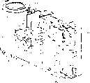
图2是一架包括图1的闪光充电和控制电路的照相机的透视图;Figure 2 is a perspective view of a camera including the flash charging and control circuit of Figure 1;
图3是一架使用图1的闪光充电和控制电路的可以回收使用的一次性使用照相机的分解透视图;Fig. 3 is an exploded perspective view of a recyclable single-use camera using the flash charging and control circuit of Fig. 1;
图4是图3中所示的一次性使用照相机的前透视图;Figure 4 is a front perspective view of the single-use camera shown in Figure 3;
图5是图3和图4中所示的一次性使用照相机机身的部分前透视图;Figure 5 is a partial front perspective view of the single-use camera body shown in Figures 3 and 4;
图6是图3-图5中所示照相机的部分分解后视图;和Figure 6 is a partially exploded rear view of the camera shown in Figures 3-5; and
图7是图6的一次性使用照相机的表示胶卷盒的重新安装的部分后视图。FIG. 7 is a partial rear view of the single-use camera of FIG. 6 showing reinstallation of the film cartridge.
优选实施例的说明Description of the preferred embodiment
现在参照附图,本发明的一个优选实施例体现在一种带闪光充电和控制电路12(图1)的廉价一次性使用照相机10中(图2)。该照相机包括机身14、光学系统16、两个操作机构18和19、一取景器20和包括闪光管24的闪光装置22。照相机机身14适合于相对其它相机元件接受照相胶卷并将其定位在一预定的曝光位置。操作机构18启动一个程序,该程序通过光学系统16并借助于从闪光装置22来的补充照明使胶卷曝光。操作机构19在曝光程序之前启动一个闪光充电周期。照相机利用取景器20对准想照的本体。Referring now to the drawings, a preferred embodiment of the present invention is embodied in an inexpensive single-use camera 10 (FIG. 2) with flash charging and control circuitry 12 (FIG. 1). The camera comprises a body 14 , an optical system 16 , two operating
在该优选实施例中,当需要时,使用者通过瞬时按下独立的操作机构19而选用闪光装置22的操作。但是,可以使用其它方法,包括与每次曝光一起的闪光操作,这对于一些具有很少几个廉价元件的一次性使用照相机是典型的。用于顺序启动充电周期和曝光周期的单一多阶段操作按钮和开关也包括在本发明的范围内。In the preferred embodiment, the user selects operation of the
闪光充电和控制电路12包括一直流电源26、一自振荡闪光充电电路28、采用电容器30形式的一电荷存储装置、一振荡止动电路32、一闪光触发电路34和闪光管24。Flash charge and
电源26包括一或多个电压预定的电池36,在该优选实施例中这些电池由照相机提供而无替换装置。The
自振荡充电电路28包括一个分别具有初级和次级绕组38和40的转换电压的变压器;一个用于在电路28中启动振荡的瞬时开关42;一个与瞬时开关串联的电阻器44;起支持和维持振荡的开关元件作用的组合晶体管46和48;以及一个对变压器的次级绕组40中感应的电流进行整流用的二极管50。The self-oscillating
充电过程是通过瞬时按下操作机构19而开始的,操作驱动机构19闭合瞬时开关42,从而通过电阻器44、晶体管46和48与变压器初级绕组38产生电流。开关42使晶体管46的基极通过电阻器44连接到电池26上。从电池流入晶体管46基极的电流通过晶体管的增益放大50倍并流入晶体管48的基极。电流在晶体管48中再次放大,其增益为200倍,并通过晶体管48的集电极和变压器初级绕组38流动。当电流在初级绕组38中形成时,它在次级绕组40中感应出电流。电流流出电容器30,对电容器充电并进入晶体管46的基极,形成正反馈。The charging process is initiated by momentarily
在某一点上基极反馈将不再支持增大电流而过程将反转。减小的初级电流产生较小的反馈电流,这意味着较小的初级电流等等,从而完成第一个微循环。下一个微循环是通过由次级绕组40中变化的场引起的晶体管46基极中的噪声开始的。另一微循环开始,而振荡继续进行。晶体管46和48产生足够的环路增益以支持振荡而不管瞬时开关42是开还是关。At some point the base feedback will no longer support increasing current and the process will reverse. The reduced primary current produces a smaller feedback current, which means smaller primary current and so on, completing the first microcycle. The next microcycle is initiated by noise in the base of
变压器初级绕组38中的振荡在次级绕组40中感应出电流。电容器30由电流充电,该电流在一个方向上通过整流二极管50流向晶体管46。Oscillation in transformer primary winding 38 induces a current in secondary winding 40 .
振荡止动电路32包括一个电压传感器52和一个数字PnP晶体管或门54。电压由与齐纳二极管58串联的操作准备指示氖灯56感知。操作准备指示氖灯在270伏时导通,但当它导通时操作准备指示灯两端的电压降降至220伏。齐纳二极管在110伏时导通。包括串联的操作准备指示灯56和齐纳二极管58的电压传感器52在330伏时开始导通,该值也代表闪光电容器30上预期的全额电荷或预定电荷。如本说明书中所用,闪光电容器上的全额电荷这一术语用来表示当闪光时用于闪光的所希望的电荷或电压。The
当电容器30两端的电压达到270伏时,操作准备指示氖灯56开始导通,点亮操作准备指示灯并提请使用人注意在闪光电容器30上已有启动曝光程序的足够电荷。但是,电容器30尚未达到全额充电,因此继续充电,直到电容器30上的电荷达到330伏。当闪光电容器30充电完全时,齐纳二极管58开始导通,将电流加到晶体管54的基极上,使晶体管54导通,并使自振荡充电电路28接地。电路中的振荡受到止动,于是充电停止。When the voltage across the
操作准备指示氖灯起几个作用。当闪光电容器的电压超过操作准备电压时氖灯导通,指示此时电容器上已有启动曝光的足够电荷。它也起电压传感触发电路中元件的作用,当闪光电容器到达一个比操作准备电压大的预定或全额电压时,该元件停止闪光电容器的充电。这使得能够在电压传感电路中使用一个额定电压较低的齐纳二极管而不需要任何附加部件。氖灯是两个电学环路的一部分,每个环路起不同的作用。第一环路包括电容器30、操作准备指示灯56和电阻器60。当电容器电荷高于操作准备电荷这个环路连续导通时操作准备指示灯点亮。第二环路包括电容器30、操作准备指示灯56、齐纳二极管58和晶体管门54。这个环路控制充电电路,当电容器电压达到预定的或全额电荷时,该环路瞬时导通而触发断开充电电路。瞬时导通瞬时增大操作准备指示灯的照明并由此指示何时达到预定电荷。The ready-to-operate neon light serves several functions. The neon lamp turns on when the voltage of the flash capacitor exceeds the operation ready voltage, indicating that there is enough charge on the capacitor to start the exposure at this time. It also acts as an element in the voltage sense trigger circuit which stops charging of the flash capacitor when the flash capacitor reaches a predetermined or full voltage greater than the operational ready voltage. This enables the use of a lower voltage rated Zener diode in the voltage sensing circuit without any additional components. The neon lamp is part of two electrical loops, each performing a different function. The first loop includes
根据该优选实施例,电压传感电路52为与齐纳二极管串联的操作准备指示氖灯。但是,根据本发明的某些特点,也可以使用其它元件。氖灯和齐纳二极管起启动晶体管门54的触发器的作用,并在闪光电容器62和晶体管54之间形成一个信号通路。其它可以用来替换二极管和灯的元件包括通过传导电子或传送光子而传送信号的元件。According to the preferred embodiment, the
电阻器44小到足以产生电流以开始振荡,而大到甚至在瞬时开关42仍然闭合时也足以能使数字晶体管54停止振荡。
闪光触发电路34用于能大批量供应的一次性使用照相机中,将不再详细说明。简言之,电路34包括触发电容器62、转换电压的变压器64、闪光触发电极66和同步开关68。触发电容器62与闪光电容器30同时和以同样方式由通过次级绕组40的电流的充电。在操作中,在曝光程序中的适当时间通过照相机快门机构闭合同步开关68。电容器62通过转换电压的变压器64的初级绕组放电,在触发电极66中感应出4千伏电压并电离闪光放电管24中的气体。然后闪光电容器30通过闪光管24放电,激发气体而产生闪光照明。The
现在应当清楚,根据本发明的振荡止动装置通过电压传感器直接耦合到闪光电容器上,并且并不通过感应元件放大或缩小或由电容性电路定时。廉价元件提供了相对精确的充电自动控制,从而减少了电池的过份消耗并使使用者可专致于摄影。本说明书和权利要求中使用的短语“直接耦合”包括主要为电阻性的耦合,包括氖灯和齐纳二极管,但不包括主要为电感性或电容性的耦合。It should now be clear that the oscillation stopper according to the present invention is coupled directly to the flash capacitor through a voltage sensor and is not amplified or demagnified by an inductive element or timed by a capacitive circuit. Inexpensive components provide relatively precise automatic control of charging, thereby reducing excessive drain on the battery and allowing the user to concentrate on photography. As used in this specification and claims, the phrase "directly coupled" includes primarily resistive coupling, including neon lamps and Zener diodes, but does not include primarily inductive or capacitive coupling.
根据本发明的另一特点和已经说明的优选实施例,闪光充电周期通过闪光装置的激励自动地重新启动。闪光触发和放电电路30、34和62中的能量转换通过次级绕组40进行作用,在晶体管46的基极中产生噪声。包括晶体管46和48的反馈环路再一次形成足够的环路增益,以支持振荡而不管瞬时开关42是打开还是闭合。自振荡充电周期重新开始,振荡像以前一样继续。According to another characteristic of the invention and the preferred embodiment already described, the flash charge cycle is automatically restarted by activation of the flash device. Energy conversion in flash trigger and discharge
电容器47在晶体管46的基极上进行滤波,使电路不会由于从例如电池振动或操作准备指示氖灯56的断开而产生的不希望有的噪声而偶然地接通。电容器47最好具有470微微法的数值,以便上述反馈环路能够克服电容器47的影响而重新开始自振荡充电周期。在图1所示的优选电路中,电容器47的数值范围可以为200微微法到1000微微法。试验了6800微微法的电容值,但根据此处的特点被认为太高了,因为当闪光产生时该电容值妨碍充电程序的重新启动。当然根据本发明的其它方面电容器47可以具有其它数值。
现在参照图3-7,闪光充电和控制电路12可以包含在一种诸如可以回收使用的一次性使用照相机100之类的照相机的装配中,该照相机有三个主要的结构部件:一个主体或框架102,一个连接在主体前面的前盖120,以及一个连续在主体后面的后盖130。Referring now to FIGS. 3-7, the flash charging and
现在更具体地参照图3所示的照相机100的分解图,主体机身102包括一对成形的内室104、106,分别用于放入胶卷盒108和卷轴110之类卷片轴。一对内室104、106相对地设置在图7中曝光门107的两边。主体机身102另外支承下列照相机部件,这些部件在连接前后盖120、130之前先连接在主体机身上:一个取象镜头112,利用保持器114和支承板116将镜头夹在其间而连接在主体机身102的前面;其中支承板有一个接触开关117;以及一个塑料取景器118。取景器118可以是一个整体取景器,包括一个支架和两个光学准直透镜,所有这些都可以用一种普通材料以一种根据共同拥有的美国专利No.5,353,165中公开的发明的单一模制工艺模制在一起。该专利的公开内容在此引为参考。同时连接在主体机身102上的有:一个包括定位板122的快门机构119,它有一个用于拔动快门片124的可以按下的快门释放部分,快门片124由弹簧123通过高能杆126偏压,高能杆126也由螺旋弹簧127偏压;一个胶卷前进和计量机构,包括一个与装载的胶卷盒108的卷轴(未示出)相啮合的指轮128,一个用于啮合胶卷齿孔的链轮132,链轮有一个伸入转动凸轮134的弹簧偏压部分,该凸轮啮合一个利用弹簧138偏压的计量杆136并带有一个接触框架计数器140用的延伸部分;一个光线挡板142,装入主体机身102的后部和曝光门107(图7)中,或者与主体机身102整体形成;以及前面说明过的包括电容器62的闪光充电和控制电路12,它安装在由电池36作动力的电路板148的后侧上。闪光充电和控制电路12最好根据该特定的实施例制成可由图4的前盖102的一次接触悬臂部分19操作。闪光装置可以包括一个合成透镜22(图5),后者公开在上面参考的共同转让的实用新型专利申请中,其公开内容在此引为参考。前盖120和后盖130通过随后讨论的机构将主体机身102夹住在一起,形成一个装配的照相机。一个装饰性的标牌152可以随后附着在完工的照相机100上,以阻止使用人打开照相机,并为产品标志和操作说明提供一个方便的位置。Referring now more specifically to the exploded view of camera 100 shown in FIG. 3,
由于多种理由,包括经济效益和环境考虑,一次性使用照相机(例如上述照相机100)被设计成在购买者曝光完所装载的胶卷并将照相机交给照片处理人对胶卷显影之后由制造商回收使用。例如参见Sakai等人的美国专利No.5,329,330。因此,照相机的某些部件被设计成经受适当次数的销售、使用、重新装配和重新销售的周期。相反,为了质量的原因,其中某些部件在每次重新装配一架照相机时应当更换。为了成功地回收使用照相机,重要的是要知道特定的重新使用的照相机部件何时不再能使用,因为(例如)它们已经达到使用期限。因此,每次一架照相机重新使用时,如下面详细说明的,根据共同拥有的美国专利No.5,021,811(其公开内容在此引为参考),可以在照相机机身和/或闪光机构上设置标记,用以指示它已经被重新装配的次数。For a number of reasons, including economic efficiency and environmental considerations, single-use cameras, such as camera 100 described above, are designed to be recycled by the manufacturer after the purchaser has exposed the loaded film and handed the camera to a photo processor for development of the film. use. See, eg, US Patent No. 5,329,330 to Sakai et al. Accordingly, certain components of the camera are designed to survive an appropriate number of cycles of sale, use, reassembly, and resale. Rather, for quality reasons, some of these parts should be replaced each time a camera is reassembled. In order to successfully recycle cameras, it is important to know when particular reused camera parts can no longer be used because (for example) they have reached the end of their useful life. Accordingly, each time a camera is reused, markings may be placed on the camera body and/or flash mechanism, as described in detail below, according to commonly owned U.S. Patent No. 5,021,811, the disclosure of which is incorporated herein by reference , to indicate the number of times it has been reassembled.
一种有效的回收使用的程序要求协调一系列竞争性的考虑。通常,制造商/回收使用人希望当照片处理人拆卸时容易接触到已曝光的胶卷。这可以保持可重复使用的元件不受损伤。另一方面,又不希望消费者/照相人接触照相机内部,因为这会增加照相机内部及其可重复使用元件的损坏和/或污染的风险。这些考虑是通过在后盖上设置通向胶卷室104的门154的特别设计来解决的(如图6中所示)。为了便于重新使用而又不损坏照相机,门154可以通过一个作为盖子的厚度减薄部分或沟槽而整体形成的活动的或可以弯曲的铰链而连接到后盖上。一种一次性使用照相机用的胶卷盒门中的活动铰链的例子公开于共同拥有的美国专利No 5,255,041中,其公开内容在此引为参考。或者是,门154可以通过与后盖整体形成的易折断的连接部分连接到后盖上并设计成可以从后盖的其余部分上折断。在两种情况下,门154的打开都可以通向胶卷盒108而不损坏或不暴露连接在照相机机身102上的照相机部件。同样,如果需要,可以在后盖130上同样设置一个第二门156,该门可以由照片处理人弯曲打开或折断,以拆出闪光电池,参见图6。An effective recycling program requires coordination of a number of competing considerations. Often, the manufacturer/recycler wishes to have easy access to the exposed film when the photoprocessor disassembles it. This keeps reusable elements from damage. On the other hand, it is undesirable for the consumer/photographer to have access to the interior of the camera, as this increases the risk of damage and/or contamination of the interior of the camera and its reusable components. These considerations are addressed by providing a specially designed door 154 on the back cover leading to the film chamber 104 (as shown in FIG. 6). To facilitate reuse without damaging the camera, door 154 may be attached to the rear cover by a movable or bendable hinge integrally formed as a reduced thickness portion or groove of the cover. An example of a living hinge in a film box door for a single use camera is disclosed in commonly owned U.S. Patent No. 5,255,041, the disclosure of which is incorporated herein by reference. Alternatively, the door 154 may be attached to the rear cover by a frangible connection integrally formed with the rear cover and designed to snap off from the remainder of the rear cover. In both cases, opening of the door 154 allows access to the
照相机100随后转交给制造商用于回收使用,现在参照图3-7说明该过程。回收使用的过程可以包括下列步骤:首先,可以从照相机机身102上拆下前盖120和后盖130。应当容易理解,前后盖120、130和机身102可以使用许多手段将结构部件连接在一起;例如,可以使用钩形件和/或压配件,或者可以将部件超声焊接在一起。因此,每个盖子可以有合适数量的常规可脱开的钩形结构件(其中之一示于161、162)或其它连接机构,以便可以从机身上拆开盖子。盖子可以用聚苯乙烯之类可回收使用的塑料制成并可送去粉碎。粉碎的原料可以与新原料混合,然后用它们模制新的盖或其它部件。The camera 100 is then transferred to the manufacturer for recycling, a process now described with reference to FIGS. 3-7. The recycling process may include the following steps: First, the
预绕的卷轴110、取像透镜112和光挡板142(除非与机身102整体模制)也可以拆卸。取像透镜112同样可以与其它透镜一起粉碎,与新原料混合,用它们制成新透镜。The pre-wound spool 110, taking lens 112 and light barrier 142 (unless integrally molded with the body 102) are also removable. The image taking lens 112 can also be crushed together with other lenses, mixed with new raw materials, and used to make new lenses.
其它部件,通常是设计成重新使用的较昂贵的元件,如主体机身102和由机身支承的主要部件如取景器118、快门机构119、胶卷前进和计量机构以及闪光充电和控制电路12,可以细心地检查其磨损或损坏情况。那些认为已损坏或已磨损的部件可以从机身102拆去并用新部件替换。那些留下来可重复使用的部件,如可以重新使用的照相机闪光充电和控制电路12、快门机构119等,仍然支承在照相机机身上,用于装配在照相机100中。Other components, typically more expensive elements designed to be reused, such as the
然后将一个新的前盖120安装在机身102的前面并将一个装在新盒108中的未曝光的胶卷109装入胶卷盒室104中。然后将装在盒108中的胶卷109的最前边部分如惯常知道的那样与罩在机身室106中的卷片卷轴110啮合。然后将一个新的后盖130卡在或用其它方式连接在照相机机身102的后面,并/或用上述任何连接机构连接到前盖120上。A new
可以使用一个不太严密但并非优选的回收使用过程,其中前后盖120、130不用新部件替换。在这种情况下,在拆卸后盖后用目视检查照相机。如果认为照相机整体可重复使用,那么可以将新的胶卷109重新装入胶卷室并装在卷片轴上。然后将后盖重新连接在照相机机身和/或前盖上。A less stringent but less preferred recycling process can be used in which the front and
在两者中任一的情况下,胶卷109而后预绕在卷片卷轴110上,后者受到支承以便在室106中转动,使得当胶卷曝光时胶卷被绕回到盒108中。在将胶卷预绕到预绕卷轴上时可以使用一个转矩有限的电动螺丝刀或其它工具。如果没有提供一个新的卷片卷轴并且预绕卷轴的曝光端部在这之前变形了因而不能将卷轴重新用于预绕目的,那么必须补加足够的热和/或压力以转动卷轴。In either case,
可以进行至少一次卷片和拔动检验(胶片前进和快门驱动),以模拟照相,由此将计数器往下设置到24(假定胶卷为曝光24张照片的)。然后可以将照相机插入一个如152的硬纸板壳或一标牌中,用胶粘剂粘结。然后可以将回收使用的照相机防潮密封在一个铝箔套、塑料袋或类似袋套中,并封装在一个外部硬纸板盒中以供销售。利用早先用过的一次性使用照相机部件如闪光充电和控制电路12之类的回收使用的一次性使用照相机100,现在已完全装配好,准备供消费者使用。At least one wind and pull test (film advance and shutter actuation) may be performed to simulate a photoshoot, thereby setting the counter down to 24 (assuming the film was exposed for 24 pictures). The camera can then be inserted into a cardboard case such as 152 or a sign and bonded with adhesive. The recycled camera can then be moisture-tight sealed in an aluminum foil sleeve, plastic bag or similar bag sleeve and packaged in an outer cardboard box for sale. The recycled single-use camera 100 utilizing previously used single-use camera components, such as the flash charge and
虽然本发明是联系一个优选实施例说明的,但对于熟悉该技术的专业人员可以进行其它修改和应用。权利要求书应当被解释为完全包括所有那些在本发明的范围和精神实质内的修改和应用。Although the invention has been described in connection with a preferred embodiment, other modifications and applications will occur to those skilled in the art. The claims should be construed to fully cover all those modifications and applications within the scope and spirit of the invention.
图1-7的部件清单10-照相机12-闪光充电和控制电路14-照相机机身16-光学系统18,19-操作机构20-取景器22-闪光装置24-闪光管26-电源28-自振荡闪光充电电路30-电容器32-振荡止动电路34-闪光触发电路36-电池38-变压器初级绕组40-变压器次级绕组42-瞬时开关44-电阻器46-晶体管47-电容器48-晶体管50-整流二极管52-电压传感器1-7 parts list 10-camera 12-flash charging and control circuit 14-camera body 16-
54-数字晶体管56-操作准备指示氖灯58-齐纳二极管62-触发电容器64-变压器66-闪光触发电极68-同步开关100一次性使用照相机102机身104胶卷盒室106卷片室107曝光门108胶卷盒109胶卷110卷片轴112取像透镜114保持器116支承板118取景器119快门机构120前盖122定位板123弹簧124快门片54-Digital Transistor 56-Operation Ready Indicator Neon Lamp 58-Zener Diode 62-Trigger Capacitor 64-Transformer 66-Flash Trigger Electrode 68-Sync Switch 100
126高能杆127螺旋弹簧128指轮130后盖132链轮134可以转动的凸轮136计量杆138弹簧140框架计数器142挡板148电路板152标牌154第一门156第二门126 high-energy rod 127
Claims (23)
Applications Claiming Priority (6)
| Application Number | Priority Date | Filing Date | Title |
|---|---|---|---|
| US26941594A | 1994-06-30 | 1994-06-30 | |
| US08/269,415 | 1994-06-30 | ||
| US32724494A | 1994-10-21 | 1994-10-21 | |
| US08/327,244 | 1994-10-21 | ||
| US08/330,658 | 1994-10-28 | ||
| US08/330,658US5574337A (en) | 1994-06-30 | 1994-10-28 | Single touch flash charger control |
Publications (2)
| Publication Number | Publication Date |
|---|---|
| CN1130460Atrue CN1130460A (en) | 1996-09-04 |
| CN1049318C CN1049318C (en) | 2000-02-09 |
Family
ID=27402178
Family Applications (1)
| Application Number | Title | Priority Date | Filing Date |
|---|---|---|---|
| CN95190600AExpired - Fee RelatedCN1049318C (en) | 1994-06-30 | 1995-06-23 | Single touch flash charger control |
Country Status (8)
| Country | Link |
|---|---|
| US (1) | US5574337A (en) |
| EP (1) | EP0716801B1 (en) |
| JP (1) | JPH09502569A (en) |
| CN (1) | CN1049318C (en) |
| AU (1) | AU682979B2 (en) |
| CA (1) | CA2169189A1 (en) |
| DE (1) | DE69523264T2 (en) |
| WO (1) | WO1996001034A2 (en) |
Cited By (3)
| Publication number | Priority date | Publication date | Assignee | Title |
|---|---|---|---|---|
| CN101285990B (en)* | 2007-04-10 | 2010-06-23 | 索尼株式会社 | Imaging apparatus, strobe device, and charging-control method |
| US8127241B2 (en) | 2004-05-04 | 2012-02-28 | Fisher-Rosemount Systems, Inc. | Process plant user interface system having customized process graphic display layers in an integrated environment |
| CN101730362B (en)* | 2008-10-27 | 2013-02-20 | 佛山普立华科技有限公司 | Flash lamp control circuit |
Families Citing this family (23)
| Publication number | Priority date | Publication date | Assignee | Title |
|---|---|---|---|---|
| EP0755174A3 (en)* | 1995-07-18 | 1998-12-16 | Eastman Kodak Company | Static immunity for single touch flash charger control |
| US6081666A (en)* | 1996-09-13 | 2000-06-27 | Concord Camera Corp. | Film and battery loading method for a single use camera such as a single use APS camera and a camera loaded according to the same |
| US6085037A (en)* | 1996-09-13 | 2000-07-04 | Concord Camera Corp. | APS camera structure for film preloading |
| US5832311A (en)* | 1996-09-13 | 1998-11-03 | Concord Camera Corp. | Single use camera with battery located in film spool |
| US5862414A (en)* | 1996-09-13 | 1999-01-19 | Concord Camera Corp. | Film and battery loading method for a single use camera such as a single use APS camera and a camera loaded according to the same |
| US5781804A (en)* | 1996-11-19 | 1998-07-14 | Eastman Kodak Company | Single touch flash charger circuit with timer control |
| US5814948A (en)* | 1997-01-14 | 1998-09-29 | Eastman Kodak Company | Flash circuit for low cost cameras |
| US5930545A (en)* | 1997-11-13 | 1999-07-27 | Eastman Kodak Company | Camera with space-saving elastomeric switch |
| US5943521A (en)* | 1998-03-10 | 1999-08-24 | Eastman Kodak Company | Camera with movable protective cover supported for pivoting to activate switch |
| US6198880B1 (en)* | 1998-05-28 | 2001-03-06 | Konica Corporation | Lens-fitted film unit having a touch sensor |
| US6054814A (en)* | 1998-09-08 | 2000-04-25 | Eastman Kodak Company | Camera flash charging apparatus for low cost single use camera |
| US6035141A (en)* | 1999-02-18 | 2000-03-07 | Eastman Kodak Company | Optical data recording circuit for a film camera |
| US6038408A (en)* | 1999-02-18 | 2000-03-14 | Eastman Kodak Company | Optical data recording circuit for a film camera |
| US6529687B1 (en) | 1999-03-30 | 2003-03-04 | Concord Camera Corp. | APS camera and method |
| US6314239B1 (en)* | 1999-06-25 | 2001-11-06 | Fuji Photo Film Co., Ltd. | Device for preventing unauthorized recycling of lens-fitted photo film unit |
| US6233402B1 (en) | 1999-10-05 | 2001-05-15 | Eastman Kodak Company | Camera frame assembly having actuable battery contact |
| US6198881B1 (en) | 1999-10-05 | 2001-03-06 | Eastman Kodak Company | Loading methods for camera frame assemblies subject to static charging during film scrolling |
| US6266491B1 (en) | 1999-10-05 | 2001-07-24 | Eastman Kodak Company | Camera frame assembly having standby battery station |
| US6574430B1 (en) | 2001-12-27 | 2003-06-03 | Eastman Kodak Company | Camera electronic system and method of assembling same |
| US6871016B2 (en) | 2001-12-27 | 2005-03-22 | Eastman Kodak Company | Recyclable camera and method for assembling same |
| US6768869B2 (en) | 2002-04-23 | 2004-07-27 | Eastman Kodak Company | Camera body, camera and method for assembling same |
| CN1305352C (en)* | 2002-12-31 | 2007-03-14 | 圆创科技股份有限公司 | Charging IC for camera flash |
| US6826365B1 (en) | 2003-10-06 | 2004-11-30 | Eastman Kodak Company | Battery saving flash charger control |
Family Cites Families (62)
| Publication number | Priority date | Publication date | Assignee | Title |
|---|---|---|---|---|
| US2933027A (en)* | 1951-10-05 | 1960-04-19 | Beaurline Ind Inc | Camera |
| US3310723A (en)* | 1963-10-18 | 1967-03-21 | Honeywell Inc | High voltage power supply for photographic flash apparatus |
| DE2039035C3 (en)* | 1969-08-09 | 1979-05-31 | Konishiroku Photo Industry Co., Ltd., Tokio | Photographic camera with built-in electronic flash |
| DE7139123U (en)* | 1970-10-16 | 1972-02-03 | Minnesota Mining And Manufacturing Co | HOUSING FOR A PHOTO APPARATUS |
| US3780344A (en)* | 1971-09-07 | 1973-12-18 | Gte Sylvania Inc | Charge regulating circuit for flash lamp storage capacitor |
| US3764849A (en)* | 1972-03-24 | 1973-10-09 | Minolta Camera Kk | Electronic flash charging and triggering circuitry |
| US4001640A (en)* | 1973-01-02 | 1977-01-04 | Polaroid Corporation | Single trigger photographic strobe unit |
| US3882358A (en)* | 1973-06-26 | 1975-05-06 | Ibm | Anti-holdover charging circuit for flash lamp |
| DE2430481A1 (en)* | 1973-06-28 | 1975-01-16 | Honeywell Inc | Electronic flash gun charging arrangement - with some magnetic energy retained in the transformer core, decreased time to charge storage capacitor |
| US3859563A (en)* | 1973-07-09 | 1975-01-07 | Lumedyne Inc | Voltage converter and regulator |
| DE2513812B1 (en)* | 1975-03-27 | 1976-09-30 | Agfa Gevaert Ag | DEVICE FOR SYNCHRONOUSLY IGNITING AN ELECTRONIC FLASH DEVICE |
| US4007469A (en)* | 1975-04-21 | 1977-02-08 | Polaroid Corporation | Photographic apparatus with plurality of selectively determinable operational modes |
| US4082983A (en)* | 1975-06-23 | 1978-04-04 | Rollei Of America, Inc. | Capacitor charging system for electronic flash apparatus |
| JPS52125318A (en)* | 1976-03-17 | 1977-10-21 | West Electric Co | Flash camera |
| DE2716824C2 (en)* | 1976-04-16 | 1982-11-18 | Fuji Photo Optical Co., Ltd., Omiya, Saitama | Electronic flash unit |
| US4065700A (en)* | 1976-07-06 | 1977-12-27 | Theodore Liebman | D. C. powered strobe light |
| JPS59957B2 (en)* | 1976-11-09 | 1984-01-09 | 株式会社セコ−技研 | electronic light emitter |
| DE2841399A1 (en)* | 1977-09-25 | 1979-03-29 | Fuji Koeki Corp | FLASH DEVICE |
| JPS5845792B2 (en)* | 1978-03-20 | 1983-10-12 | ウエスト電気株式会社 | electronic flash device |
| JPS55141970A (en)* | 1979-04-21 | 1980-11-06 | Yoshiyuki Takematsu | Power supply device |
| US4322143A (en)* | 1979-06-27 | 1982-03-30 | Balda-Werke | Electronic flash for a camera |
| JPS5676199A (en)* | 1979-11-26 | 1981-06-23 | Fuji Koeki Corp | Power source for flasher |
| US4441774A (en)* | 1980-05-14 | 1984-04-10 | Nippon Kogaku K.K. | Flash device of a camera |
| US4348087A (en)* | 1981-04-03 | 1982-09-07 | Polaroid Corporation | Photographic system for automatically charging electronic flash |
| NL8202259A (en)* | 1982-06-04 | 1984-01-02 | Philips Nv | POWER SUPPLY CONTAINING AN AC POWER SUPPLY SOURCE, A LOAD AND A CONNECTION CABLE BETWEEN SOURCE AND LOAD. |
| US4566769A (en)* | 1982-12-29 | 1986-01-28 | Olympus Optical Co., Ltd. | Power supply unit for electronic flash |
| GB2133644A (en)* | 1983-01-14 | 1984-07-25 | Fuji Koeki Corp | Photographic flash apparatus |
| US4540265A (en)* | 1983-01-24 | 1985-09-10 | Eastman Kodak Company | Energy-saving electronic flash apparatus |
| US4628229A (en)* | 1983-02-15 | 1986-12-09 | Olympus Optical Company, Ltd | Flashlight emission apparatus |
| DE8717158U1 (en)* | 1986-08-20 | 1988-06-23 | Fuji Photo Film Co., Ltd., Minami-Ashigara, Kanagawa | Photographic film pack |
| DE3735116C2 (en)* | 1986-10-17 | 1997-01-30 | Fuji Photo Film Co Ltd | Disposable camera |
| DE8717160U1 (en)* | 1986-12-01 | 1988-06-01 | Fuji Photo Film Co., Ltd., Minami-Ashigara, Kanagawa | A photographic film package equipped with a lens |
| EP0272701B1 (en)* | 1986-12-23 | 1993-04-21 | Asahi Kogaku Kogyo Kabushiki Kaisha | Apparatus for controlling charging of main capacitor of flash unit |
| GB2200760B (en)* | 1987-02-06 | 1991-11-06 | Fuji Photo Film Co Ltd | Photographic film package |
| US4812863A (en)* | 1987-02-17 | 1989-03-14 | Fuji Photo Film Co., Ltd. | Lens-fitted photographic film package |
| US4777507A (en)* | 1988-01-20 | 1988-10-11 | Eastman Kodak Company | Control system for an electronic flash unit |
| US4994846A (en)* | 1988-04-11 | 1991-02-19 | Asahi Kogaku Kogyo Kabushiki Kaisha | Auto strobe camera |
| US4989029A (en)* | 1988-04-20 | 1991-01-29 | Minolta Camera Kabushiki Kaisha | Camera with control apparatus for charging storage capacitor for flash light emission |
| US5138362A (en)* | 1988-06-30 | 1992-08-11 | Asahikogaku Kogyo Kabushiki Kaisha | Auto strobe camera |
| US4912499A (en)* | 1989-01-17 | 1990-03-27 | Eastman Kodak Company | Camera apparatus |
| US4970439A (en)* | 1989-04-28 | 1990-11-13 | Minnesota Mining And Manufacturing Company | Power supply circuit for a gaseous discharge tube device |
| US5019845A (en)* | 1989-06-23 | 1991-05-28 | Olympus Optical Co., Ltd. | Flash device for camera |
| JP2790243B2 (en)* | 1989-08-01 | 1998-08-27 | 三井化学株式会社 | Culture device |
| US5021811A (en)* | 1990-06-21 | 1991-06-04 | Eastman Kodak Company | Recycleable element recycle counter and method |
| DE69127594T2 (en)* | 1990-07-09 | 1998-01-22 | Fuji Photo Film Co Ltd | Main body of a camera equipped with a lens |
| US5101335A (en)* | 1990-12-26 | 1992-03-31 | Eastman Kodak Company | DC-to-DC converter using coupled inductor current sensing and predetermined on time |
| US5068575A (en)* | 1991-02-21 | 1991-11-26 | Eastman Kodak Company | Indirect storage capacitor voltage sensing means for a flyback type DC-to-DC converter |
| US5315332A (en)* | 1991-04-11 | 1994-05-24 | Fuji Photo Film Co., Ltd. | Lens-fitted photographic film package and flash unit |
| JP3297446B2 (en)* | 1991-06-26 | 2002-07-02 | ウエスト電気株式会社 | Strobe device |
| JP2951450B2 (en)* | 1991-09-30 | 1999-09-20 | 富士写真光機株式会社 | Film unit with lens |
| JPH05210210A (en)* | 1992-01-31 | 1993-08-20 | Konica Corp | Film unit with lens |
| US5337099A (en)* | 1992-07-01 | 1994-08-09 | Fuji Photo Film Co., Ltd. | Lens-fitted photographic film unit with flash device and battery-insulating wrapper |
| JPH0643525A (en)* | 1992-07-23 | 1994-02-18 | Fuji Photo Film Co Ltd | Stroboscoptic device |
| US5353165A (en)* | 1992-09-15 | 1994-10-04 | Eastman Kodak Company | One piece viewfinder and fabrication process |
| JPH06130469A (en)* | 1992-10-15 | 1994-05-13 | Fuji Photo Film Co Ltd | Film unit having lens with built-in strobe |
| US5287134A (en)* | 1992-12-28 | 1994-02-15 | Eastman Kodak Company | Photographic flash apparatus |
| JPH06203989A (en)* | 1993-01-04 | 1994-07-22 | Fuji Photo Film Co Ltd | Stroboscopic device |
| JPH06202208A (en)* | 1993-01-04 | 1994-07-22 | Fuji Photo Film Co Ltd | Charging switch device for stroboscope |
| JPH06203987A (en)* | 1993-01-07 | 1994-07-22 | Fuji Photo Film Co Ltd | Stroboscope charging switch device |
| JPH06203988A (en)* | 1993-01-07 | 1994-07-22 | Fuji Photo Film Co Ltd | Stroboscopic power source circuit and camera using this |
| JP3574154B2 (en)* | 1993-01-11 | 2004-10-06 | 富士写真フイルム株式会社 | Strobe dimming circuit |
| US5255041A (en)* | 1993-02-11 | 1993-10-19 | Eastman Kodak Company | Single-use camera with door for cartridge receiving chamber |
- 1994
- 1994-10-28USUS08/330,658patent/US5574337A/ennot_activeExpired - Lifetime
- 1995
- 1995-06-23WOPCT/US1995/008908patent/WO1996001034A2/enactiveIP Right Grant
- 1995-06-23DEDE69523264Tpatent/DE69523264T2/ennot_activeExpired - Fee Related
- 1995-06-23CACA002169189Apatent/CA2169189A1/ennot_activeAbandoned
- 1995-06-23AUAU32703/95Apatent/AU682979B2/ennot_activeCeased
- 1995-06-23EPEP95929311Apatent/EP0716801B1/ennot_activeExpired - Lifetime
- 1995-06-23JPJP8503503Apatent/JPH09502569A/enactivePending
- 1995-06-23CNCN95190600Apatent/CN1049318C/ennot_activeExpired - Fee Related
Cited By (3)
| Publication number | Priority date | Publication date | Assignee | Title |
|---|---|---|---|---|
| US8127241B2 (en) | 2004-05-04 | 2012-02-28 | Fisher-Rosemount Systems, Inc. | Process plant user interface system having customized process graphic display layers in an integrated environment |
| CN101285990B (en)* | 2007-04-10 | 2010-06-23 | 索尼株式会社 | Imaging apparatus, strobe device, and charging-control method |
| CN101730362B (en)* | 2008-10-27 | 2013-02-20 | 佛山普立华科技有限公司 | Flash lamp control circuit |
Also Published As
| Publication number | Publication date |
|---|---|
| AU3270395A (en) | 1996-01-25 |
| EP0716801B1 (en) | 2001-10-17 |
| JPH09502569A (en) | 1997-03-11 |
| CN1049318C (en) | 2000-02-09 |
| US5574337A (en) | 1996-11-12 |
| WO1996001034A2 (en) | 1996-01-11 |
| WO1996001034A3 (en) | 1996-02-22 |
| AU682979B2 (en) | 1997-10-23 |
| DE69523264D1 (en) | 2001-11-22 |
| EP0716801A1 (en) | 1996-06-19 |
| DE69523264T2 (en) | 2002-07-11 |
| CA2169189A1 (en) | 1996-01-11 |
Similar Documents
| Publication | Publication Date | Title |
|---|---|---|
| CN1130460A (en) | One Touch Flash Charger Control | |
| JP2594061Y2 (en) | Film unit with lens | |
| US5506646A (en) | Test firing of a photographic flash assembly | |
| US6054814A (en) | Camera flash charging apparatus for low cost single use camera | |
| JP2858715B2 (en) | Film unit with lens | |
| JP3452954B2 (en) | Strobe circuit | |
| EP1727400A1 (en) | Flash device | |
| JP2004125973A (en) | Lens-fitted photographic film unit | |
| US6381414B2 (en) | Oscillation circuit and strobe device employing the oscillation circuit | |
| JPH06267548A (en) | Battery unit | |
| JPH06203989A (en) | Stroboscopic device | |
| JP2593342Y2 (en) | Film unit with lens | |
| CN1811578A (en) | Flash unit | |
| JPH06347872A (en) | Stroboscope device | |
| JPH11183979A (en) | Film integrated type camera | |
| EP1091242A1 (en) | Loading methods for camera frame assemblies subject to static charging during film scrolling | |
| JPH1164940A (en) | Film unit with lens | |
| JPH10232433A (en) | Stroboscopic unit and film unit with lens provided with built-in stroboscope | |
| JP2004047826A (en) | Circuit component mounting board | |
| JPH0954362A (en) | Stroboscope incorporating type film unit with lens and its manufacture | |
| JPH1195292A (en) | Stroboscopic circuit | |
| JP2000347258A (en) | Stroboscopic device | |
| JPH0915692A (en) | Stroboscopic circuit | |
| JP2003280077A (en) | Camera | |
| JPH01310333A (en) | Stroboscopic photographing device |
Legal Events
| Date | Code | Title | Description |
|---|---|---|---|
| C06 | Publication | ||
| PB01 | Publication | ||
| C10 | Entry into substantive examination | ||
| SE01 | Entry into force of request for substantive examination | ||
| C14 | Grant of patent or utility model | ||
| GR01 | Patent grant | ||
| C17 | Cessation of patent right | ||
| CF01 | Termination of patent right due to non-payment of annual fee | Granted publication date:20000209 Termination date:20100623 |