CN113040864B - Aiming positioner for external fixation nail - Google Patents
Aiming positioner for external fixation nailDownload PDFInfo
- Publication number
- CN113040864B CN113040864BCN202110334079.1ACN202110334079ACN113040864BCN 113040864 BCN113040864 BCN 113040864BCN 202110334079 ACN202110334079 ACN 202110334079ACN 113040864 BCN113040864 BCN 113040864B
- Authority
- CN
- China
- Prior art keywords
- hook
- slider
- backbone
- hole
- traction
- Prior art date
- Legal status (The legal status is an assumption and is not a legal conclusion. Google has not performed a legal analysis and makes no representation as to the accuracy of the status listed.)
- Expired - Fee Related
Links
- 238000009434installationMethods0.000claimsdescription18
- 238000011084recoveryMethods0.000claimsdescription3
- 238000004804windingMethods0.000claimsdescription2
- 239000011111cardboardSubstances0.000claims1
- 238000005553drillingMethods0.000abstractdescription13
- 239000002184metalSubstances0.000description6
- 210000001519tissueAnatomy0.000description6
- 238000000034methodMethods0.000description5
- 210000000988bone and boneAnatomy0.000description4
- 208000010392Bone FracturesDiseases0.000description3
- 206010017076FractureDiseases0.000description3
- 230000009286beneficial effectEffects0.000description3
- 238000004140cleaningMethods0.000description3
- 238000012423maintenanceMethods0.000description3
- 208000002565Open FracturesDiseases0.000description2
- 208000002193PainDiseases0.000description2
- 208000027418Wounds and injuryDiseases0.000description2
- 230000006378damageEffects0.000description2
- 238000010586diagramMethods0.000description2
- 208000014674injuryDiseases0.000description2
- 230000007774longtermEffects0.000description2
- 210000004872soft tissueAnatomy0.000description2
- 206010031252OsteomyelitisDiseases0.000description1
- 208000004550Postoperative PainDiseases0.000description1
- 206010065769Soft tissue necrosisDiseases0.000description1
- 229910000831SteelInorganic materials0.000description1
- 230000003044adaptive effectEffects0.000description1
- 230000007547defectEffects0.000description1
- 230000007812deficiencyEffects0.000description1
- 239000012634fragmentSubstances0.000description1
- 208000015181infectious diseaseDiseases0.000description1
- 238000003780insertionMethods0.000description1
- 230000037431insertionEffects0.000description1
- 238000012986modificationMethods0.000description1
- 230000004048modificationEffects0.000description1
- 210000003205muscleAnatomy0.000description1
- 230000000399orthopedic effectEffects0.000description1
- 230000001681protective effectEffects0.000description1
- 230000000717retained effectEffects0.000description1
- 229910001220stainless steelInorganic materials0.000description1
- 239000010935stainless steelSubstances0.000description1
- 239000010959steelSubstances0.000description1
- 238000004659sterilization and disinfectionMethods0.000description1
- 230000008685targetingEffects0.000description1
Images


Classifications
- A—HUMAN NECESSITIES
- A61—MEDICAL OR VETERINARY SCIENCE; HYGIENE
- A61B—DIAGNOSIS; SURGERY; IDENTIFICATION
- A61B17/00—Surgical instruments, devices or methods
- A61B17/16—Instruments for performing osteoclasis; Drills or chisels for bones; Trepans
- A61B17/17—Guides or aligning means for drills, mills, pins or wires
- A61B17/171—Guides or aligning means for drills, mills, pins or wires for external fixation
- A—HUMAN NECESSITIES
- A61—MEDICAL OR VETERINARY SCIENCE; HYGIENE
- A61B—DIAGNOSIS; SURGERY; IDENTIFICATION
- A61B17/00—Surgical instruments, devices or methods
- A61B17/56—Surgical instruments or methods for treatment of bones or joints; Devices specially adapted therefor
- A61B17/58—Surgical instruments or methods for treatment of bones or joints; Devices specially adapted therefor for osteosynthesis, e.g. bone plates, screws or setting implements
- A61B17/88—Osteosynthesis instruments; Methods or means for implanting or extracting internal or external fixation devices
- A—HUMAN NECESSITIES
- A61—MEDICAL OR VETERINARY SCIENCE; HYGIENE
- A61B—DIAGNOSIS; SURGERY; IDENTIFICATION
- A61B90/00—Instruments, implements or accessories specially adapted for surgery or diagnosis and not covered by any of the groups A61B1/00 - A61B50/00, e.g. for luxation treatment or for protecting wound edges
- A61B90/10—Instruments, implements or accessories specially adapted for surgery or diagnosis and not covered by any of the groups A61B1/00 - A61B50/00, e.g. for luxation treatment or for protecting wound edges for stereotaxic surgery, e.g. frame-based stereotaxis
- A61B90/14—Fixators for body parts, e.g. skull clamps; Constructional details of fixators, e.g. pins
Landscapes
- Health & Medical Sciences (AREA)
- Surgery (AREA)
- Life Sciences & Earth Sciences (AREA)
- Medical Informatics (AREA)
- Animal Behavior & Ethology (AREA)
- Orthopedic Medicine & Surgery (AREA)
- Veterinary Medicine (AREA)
- Engineering & Computer Science (AREA)
- Biomedical Technology (AREA)
- Heart & Thoracic Surgery (AREA)
- Public Health (AREA)
- Molecular Biology (AREA)
- Nuclear Medicine, Radiotherapy & Molecular Imaging (AREA)
- General Health & Medical Sciences (AREA)
- Oral & Maxillofacial Surgery (AREA)
- Dentistry (AREA)
- Neurosurgery (AREA)
- Pathology (AREA)
- Surgical Instruments (AREA)
- Orthopedics, Nursing, And Contraception (AREA)
Abstract
Description
Translated fromChinese技术领域technical field
本发明涉及医疗器械技术领域,更具体地说,它涉及一种外固定置钉瞄准定位器。The invention relates to the technical field of medical instruments, more specifically, it relates to an external fixation nail aiming locator.
背景技术Background technique
车祸、高处坠落等高暴力致伤因素的逐年增加,皮肤软组织缺损破裂、缺乏组织覆盖的开放性骨折患者也迅速增多,对于开放性骨折、脱位的治疗传统的内固定方法常常面临着软组织坏死、钢板外露、骨外露感染、骨髓炎等多种并发症,治疗十分棘手,外固定支架的使用为这类损伤的治疗提供了合适的解决方案。High-violence injury factors such as car accidents and falls from heights are increasing year by year, and patients with open fractures with ruptured skin and soft tissue defects and lack of tissue coverage are also rapidly increasing. Traditional internal fixation methods for the treatment of open fractures and dislocations often face soft tissue necrosis , steel plate exposure, bone exposure infection, osteomyelitis and other complications, the treatment is very difficult, the use of external fixation brackets provides a suitable solution for the treatment of such injuries.
使用外固定支架时通常在远离骨折部位的骨块上拧入金属螺纹针,然后通过金属或非金属材质的连接杆、夹具将金属螺纹针固定相连,达到间接固定骨折的目的。When using external fixation brackets, metal threaded pins are usually screwed into the bone fragment away from the fracture site, and then the metal threaded pins are fixedly connected through metal or non-metallic connecting rods and clamps to achieve the purpose of indirect fracture fixation.
在此过程中,金属螺纹针的准确置入成为手术成功的关键性因素,但在长期的临床实践中,骨科医师经常面临着许多挑战,比较常见的有:During this process, the accurate placement of metal threaded needles has become a key factor for the success of the operation, but in long-term clinical practice, orthopedic surgeons often face many challenges, the more common ones are:
1、置钉时无法有效控制骨折断端,骨段不稳定造成置钉困难;1. The broken end of the fracture cannot be effectively controlled when placing the nail, and the unstable bone segment makes it difficult to insert the nail;
2、置钉时入钉点确定困难,进钉角度难于判断,螺钉偏心拧入造成螺钉在骨骼中的有效工作距离不足,影响金属钉固定强度;2. It is difficult to determine the nail entry point and the angle of entry of the nail when placing the nail. The eccentric screwing of the screw results in insufficient effective working distance of the screw in the bone, which affects the fixation strength of the metal nail;
3、置钉深度难于判断,置钉过浅固定强度下降,置钉过深刺激对侧软组织造成术后疼痛。3. It is difficult to judge the depth of nail placement. If the nail placement is too shallow, the fixation strength will decrease. If the nail placement is too deep, it will stimulate the contralateral soft tissue and cause postoperative pain.
以往金属螺纹钉的安全有效置入仅仅依靠临床医师的个人临床经验,学习期限较长,同质化程度低,在对需要置钉的骨干背面进行钻孔时,骨干背面的组织防护范围不方便根据实际使用的需求进行适应性的调节。In the past, the safe and effective insertion of metal threaded screws only relied on the clinician's personal clinical experience, the learning period was long, and the degree of homogeneity was low. When drilling the back of the backbone where the screw needs to be placed, the tissue protection range on the back of the backbone is inconvenient. Adaptive adjustments are made according to the needs of actual use.
为此,我们提出一种外固定螺钉置钉瞄准定位器来标准化手术过程,保护患者安全,提高手术疗效。To this end, we propose an external fixation screw targeting locator to standardize the surgical process, protect patient safety, and improve surgical efficacy.
发明内容Contents of the invention
针对现有技术存在的不足,本发明的目的在于提供一种外固定置钉瞄准定位器,其方便牵引绳穿过导向孔后对牵引滑块产生推力,牵引滑块受到推力影响时能够带动伸展挂钩在固定挂钩的内侧继续进行伸展,用于增加骨干钻孔时的防护范围,根据实际使用的需求调节伸展挂钩的伸展范围,从而控制骨干钻孔时骨干背面的防护范围。In view of the deficiencies in the prior art, the purpose of the present invention is to provide an external fixation nail aiming locator, which facilitates the traction rope to generate thrust on the traction slider after passing through the guide hole, and the traction slider can be driven to stretch when affected by the thrust The hook continues to extend on the inside of the fixed hook to increase the protection range when the backbone is drilled, and adjust the extension range of the extension hook according to the actual use requirements, thereby controlling the protection range on the back of the backbone when the backbone is drilled.
为实现上述目的,本发明提供了如下技术方案:To achieve the above object, the present invention provides the following technical solutions:
一种外固定置钉瞄准定位器,包括连接架和瞄准导向件,包括:An aiming positioner for external fixation nails, comprising a connecting frame and an aiming guide, including:
连接滑块,所述连接滑块的表面活动连接于所述连接架的内侧;A connecting slider, the surface of the connecting slider is movably connected to the inner side of the connecting frame;
连接杆,所述连接杆的一端固定连接于所述连接滑块的表面,所述连接杆的内部开设有导向孔;A connecting rod, one end of the connecting rod is fixedly connected to the surface of the connecting slider, and a guide hole is opened inside the connecting rod;
固定挂钩,所述固定挂钩的一端安装于所述连接杆的一端,所述固定挂钩的内侧开设有伸缩滑槽和限位滑槽;A fixed hook, one end of the fixed hook is installed on one end of the connecting rod, and the inner side of the fixed hook is provided with a telescopic chute and a limit chute;
伸展挂钩,所述伸展挂钩活动安装于所述伸缩滑槽的内侧,所述伸展挂钩的外侧固定连接有牵引滑块,所述牵引滑块上连接有牵引绳。An extension hook is movably installed on the inner side of the telescopic chute, and a traction slider is fixedly connected to the outside of the extension hook, and a traction rope is connected to the traction slider.
通过采用上述技术方案,通过牵引绳穿过导向孔后对牵引滑块产生推力,牵引滑块受到推力影响时能够带动伸展挂钩在固定挂钩的内侧继续进行伸展,用于增加骨干钻孔时的防护范围,根据实际使用的需求调节伸展挂钩的伸展范围,从而控制骨干钻孔时骨干背面的防护范围。By adopting the above technical scheme, the traction rope generates a thrust on the traction slider after passing through the guide hole, and when the traction slider is affected by the thrust, it can drive the extension hook to continue stretching on the inner side of the fixed hook, which is used to increase the protection of the backbone when drilling Range, adjust the extension range of the extension hook according to the needs of actual use, so as to control the protection range of the back of the backbone when the backbone is drilled.
进一步的,所述连接架的内侧开设有调节滑槽,所述连接架的顶端开设有连接滑孔,所述连接滑块的顶端开设有锁定槽,所述连接滑孔的上方设置有锁定螺栓,所述锁定螺栓用于连接所述连接滑块和所述连接架。Further, the inner side of the connecting frame is provided with an adjustment chute, the top of the connecting frame is provided with a connecting sliding hole, the top of the connecting slider is provided with a locking groove, and a locking bolt is arranged above the connecting sliding hole , the locking bolt is used to connect the connecting slider and the connecting frame.
通过采用上述技术方案,锁定螺栓通过连接滑孔的内部与锁定槽的内部螺纹连接,用于对移动调节后的连接滑块进行限位和固定,保障连接架在使用时表面与连接滑块之间的稳定性,需要调节时,只需要松动锁定螺栓即可。By adopting the above technical scheme, the locking bolt is threaded through the inside of the connecting slide hole and the inside of the locking groove, and is used to limit and fix the moving and adjusted connecting slider, so as to ensure the distance between the surface of the connecting frame and the connecting slider when in use. The stability of the space, when you need to adjust, you only need to loosen the locking bolt.
进一步的,所述连接架的表面为弧形结构,所述连接架的一端活动安装有挡块。Further, the surface of the connecting frame has an arc-shaped structure, and a stopper is movably installed at one end of the connecting frame.
通过采用上述技术方案,弧形分布的连接架方便连接滑块在弧形轨迹上移动,从而保障连接架的圆心和固定挂钩的圆心保持不变。By adopting the above technical solution, the arc-shaped connecting frame facilitates the movement of the connecting slider on the arc-shaped track, thereby ensuring that the center of circle of the connecting frame and the center of circle of the fixed hook remain unchanged.
进一步的,所述连接滑块的表面为弧形燕尾结构,所述调节滑槽的内表面为弧形燕尾滑轨的结构。Further, the surface of the connecting slider is an arc-shaped dovetail structure, and the inner surface of the adjusting chute is an arc-shaped dovetail slide rail structure.
通过采用上述技术方案,燕尾结构的连接滑块和调节滑槽为连接滑块的滑动提供支撑和限位的作用。By adopting the above technical solution, the connecting slider and the adjusting chute of the dovetail structure provide support and position limitation for the sliding of the connecting slider.
进一步的,所述连接杆的内部分别开设有安装槽和限位孔,所述固定挂钩的一端固定连接有连接组件,所述连接组件包括连接卡板和卡孔。Further, the inside of the connecting rod is respectively provided with a mounting groove and a limiting hole, and one end of the fixing hook is fixedly connected with a connecting component, and the connecting component includes a connecting clamp plate and a clamping hole.
通过采用上述技术方案,连接杆的一端通过安装槽和固定挂钩上的连接卡板卡接,卡接后通过连接螺钉进行锁紧固定,方便连接杆和固定挂钩之间的拆分,以便于固定挂钩后期的清理和维护。By adopting the above technical scheme, one end of the connecting rod is clamped through the installation groove and the connecting clip on the fixing hook, and after the clamping, it is locked and fixed by the connecting screw, which facilitates the splitting between the connecting rod and the fixing hook, so as to facilitate fixing Post-hook cleaning and maintenance.
进一步的,所述连接卡板的表面卡入所述安装槽的内部,所述卡孔和所述限位孔在同一轴线上。Further, the surface of the connection clamping plate is clamped into the inside of the installation groove, and the clamping hole and the limiting hole are on the same axis.
通过采用上述技术方案,方便连接螺钉的拧紧或拆卸。By adopting the above technical solution, the tightening or dismounting of the connecting screw is facilitated.
进一步的,所述固定挂钩的内表面为四分之一圆的弧形结构,并且固定挂钩和所述伸展挂钩的圆心重合。Further, the inner surface of the fixing hook is a quarter-circle arc structure, and the centers of the fixing hook and the extending hook coincide.
通过采用上述技术方案,能够贴合患者骨干的表面深入,降低固定挂钩插入使用时的操作难度,同圆心的伸展挂钩在伸展时能够更贴合骨干的外表面。By adopting the above-mentioned technical solution, it can fit deeply to the surface of the patient's backbone, and reduce the operational difficulty when the fixing hook is inserted into use.
进一步的,所述连接架的圆心和所述固定挂钩的圆心重合,所述瞄准导向件的轴线与所述固定挂钩的圆心相交。Further, the center of circle of the connecting frame coincides with the center of circle of the fixed hook, and the axis of the aiming guide intersects the center of circle of the fixed hook.
通过采用上述技术方案,保持瞄准导向件的轴线和固定挂钩的圆心重合,使得瞄准导向件位置的调节不会造成钻孔位置偏离固定挂钩和伸展挂钩的保护范围。By adopting the above technical solution, the axis of the aiming guide is kept coincident with the center of the fixed hook, so that the adjustment of the position of the aiming guide will not cause the drilling position to deviate from the protection range of the fixed hook and the extending hook.
进一步的,所述连接杆的外表面设置握把,握把的表面为圆柱形,且外表面采用波纹结构。Further, a handle is provided on the outer surface of the connecting rod, the surface of the handle is cylindrical, and the outer surface adopts a corrugated structure.
通过采用上述技术方案,避免手指抓住连接杆进行使用时发生打滑,以便于操作医生工作持握和使用。By adopting the above-mentioned technical solution, it is possible to avoid slippage when the fingers grasp the connecting rod for use, so that the operating doctor can hold and use it conveniently.
进一步的,所述安装槽的内部与所述限位孔的内部之间交叉分布,所述连接组件的表面通过连接螺钉与所述安装槽的内表面连接。Further, the inside of the installation groove and the inside of the limiting hole are intersected, and the surface of the connecting component is connected to the inner surface of the installation groove through connecting screws.
通过采用上述技术方案,交叉分布的安装槽和限位孔方便连接螺钉的安装和拆卸。By adopting the above technical solution, the cross-distributed installation grooves and limit holes facilitate the installation and removal of the connecting screws.
综上所述,本发明主要具有以下有益效果:In summary, the present invention mainly has the following beneficial effects:
本发明,通过牵引绳穿过导向孔后对牵引滑块产生推力,牵引滑块受到推力影响时能够带动伸展挂钩在固定挂钩的内侧继续进行伸展,用于增加骨干钻孔时的防护范围,根据实际使用的需求调节伸展挂钩的伸展范围,从而控制骨干钻孔时骨干背面的防护范围。In the present invention, after the traction rope passes through the guide hole, a thrust is generated on the traction slider. When the traction slider is affected by the thrust, the extension hook can be driven to continue extending inside the fixed hook, which is used to increase the protection range when the backbone is drilled. The actual use needs to adjust the extension range of the extension hook, so as to control the protection range of the back of the backbone when the backbone is drilled.
附图说明Description of drawings
图1为本发明提供的一种较佳实施例的整体的三维图;Fig. 1 is the overall three-dimensional diagram of a kind of preferred embodiment provided by the present invention;
图2为本发明图1中连接杆和固定挂钩部分的截面图;Fig. 2 is the sectional view of connecting rod and fixed hook part in Fig. 1 of the present invention;
图3为本发明图2中A部的放大图;Fig. 3 is the enlarged view of part A in Fig. 2 of the present invention;
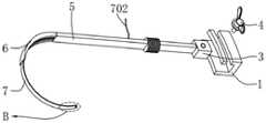
图4为本发明提供的伸展挂钩展开的状态图;Fig. 4 is a state diagram of the unfolded extension hook provided by the present invention;
图5为本发明图4中B部的放大图;Fig. 5 is the enlarged view of part B in Fig. 4 of the present invention;
图6为本发明图1中连接架部分的截面图;Fig. 6 is a sectional view of the connector part in Fig. 1 of the present invention;
图7为本发明提供的固定挂钩拆卸后使用的状态图。Fig. 7 is a state view of the fixed hook provided by the present invention after it is disassembled and used.
图中:In the picture:
1、连接架,101、调节滑槽,102、连接滑孔;1, connecting frame, 101, adjusting chute, 102, connecting sliding hole;
2、瞄准导向件;2. Aiming guide;
3、连接滑块,301、锁定槽;3. connecting slider, 301, locking groove;
4、锁定螺栓;4. Locking bolts;
5、连接杆,501、引导孔,502、安装槽,503、限位孔;5. Connecting rod, 501, guide hole, 502, installation groove, 503, limit hole;
6、固定挂钩,601、伸缩滑槽,602、限位滑槽;6. Fixed hook, 601, telescopic chute, 602, limit chute;
7、伸展挂钩,701、牵引滑块,702、牵引绳,703、扣孔;7. Extension hook, 701, traction slider, 702, traction rope, 703, buttonhole;
8、连接组件,801、连接卡板,802、卡孔;8. Connecting components, 801, connecting clamping plate, 802, clamping holes;
9、连接螺钉。9. Connect the screws.
具体实施方式detailed description
以下结合附图1-7对本发明作进一步详细说明。The present invention will be described in further detail below in conjunction with accompanying drawings 1-7.
一种外固定置钉瞄准定位器,如图1-4所示,包括连接架1和瞄准导向件2,包括:An external fixation nail aiming positioner, as shown in Figure 1-4, includes a connecting
连接滑块3,所述连接滑块3的表面活动连接于所述连接架1的内侧;A connecting
连接杆5,所述连接杆5的一端固定连接于所述连接滑块3的表面,所述连接杆5的内部开设有导向孔501;A connecting
固定挂钩6,所述固定挂钩6的一端安装于所述连接杆5的一端,所述固定挂钩6的内侧开设有伸缩滑槽601和限位滑槽602;A fixed
伸展挂钩7,所述伸展挂钩7活动安装于所述伸缩滑槽601的内侧,所述伸展挂钩7的外侧固定连接有牵引滑块701,所述牵引滑块701上连接有牵引绳702。The
在连接杆5的尾端的固定挂钩6用于对患者骨干钻孔时背面组织的防护,通过牵引绳702穿过导向孔501后对牵引滑块701产生推力,牵引滑块701受到推力影响时能够带动伸展挂钩7在固定挂钩6的内侧继续进行伸展,用于增加骨干钻孔时的防护范围,根据实际使用的需求调节伸展挂钩7的伸展范围,从而控制骨干钻孔时骨干背面的防护范围。The fixed
其中,瞄准导向件2与连接架1之间采用螺纹连接的方式进行安装和拆卸,以便于对不同尺寸的瞄准导向件2的安装和更换,从而适应不同尺寸的钻头导向孔。Wherein, the aiming
另外,牵引滑块701的表面与限位滑槽602的内表面滑动连接,牵引滑块701和限位滑槽602之间采用T型的限位滑动结构,防止牵引滑块701活动时脱离限位滑槽602的内部;In addition, the surface of the
伸展挂钩7的内壁与固定挂钩6的内壁在同一弧面上,以保障固定挂钩6贴合骨干表面时的稳定性。The inner wall of the
较佳地,如图2所示,所述固定挂钩6的内表面为四分之一圆的弧形结构,并且固定挂钩6和所述伸展挂钩7的圆心重合。Preferably, as shown in FIG. 2 , the inner surface of the fixed
四分之一圆的固定挂钩6能够贴合患者骨干的表面深入,降低固定挂钩6插入使用时的操作难度,同圆心的伸展挂钩7在伸展时能够更贴合骨干的外表面。The fixed
较佳地,如图1所示,所述连接架1的圆心和所述固定挂钩6的圆心重合,所述瞄准导向件2的轴线与所述固定挂钩6的圆心相交。Preferably, as shown in FIG. 1 , the center of circle of the connecting
连接架1上的凹槽部分的圆心与连接架1的圆心相同,使得连接杆5通过连接滑块3在连接架1上滑动时,保持瞄准导向件2的轴线和固定挂钩6的圆心重合,使得瞄准导向件2位置的调节不会造成钻孔位置偏离固定挂钩6和伸展挂钩7的保护范围。The center of circle of the groove portion on the connecting
较佳地,如图1所示,所述连接杆5的外表面设置握把,握把的表面为圆柱形,且外表面采用波纹结构。Preferably, as shown in FIG. 1 , a handle is provided on the outer surface of the connecting
波纹形状握把的设置增大手与连接杆5之间的摩擦力,避免手指抓住连接杆5进行使用时发生打滑,以便于操作医生工作持握和使用。The corrugated handle increases the friction between the hand and the connecting
工作原理:working principle:
该外固定置钉瞄准定位器,通过弧形的固定挂钩6包覆在患者骨干钻孔位置的背面,对钻孔时骨干背面的组织进行防护,同时四分之一圆的弧形结构方便贴合患者的骨干的表面,降低使用时操作的难度;The external fixation nail aims at the locator, and covers the back of the patient's backbone drilling position through the arc-shaped
固定挂钩6内侧的伸展挂钩7通过牵引绳702方便进行推拉伸展,以控制骨干背面的防护范围,从而适应面准导向件2对不同方向的钻孔防护需求。The
使用方法:Instructions:
使用时,优先在患者需要进行置钉部分的皮肤表面开口,一只手持握连接杆5,另一只手持握连接架1,将固定挂钩6从开口处插入且贴合骨干的外表面,保持固定挂钩6的内表面与骨干的表面贴合;When in use, first open the skin surface where the nail needs to be placed on the patient, hold the connecting
当需要增加固定挂钩6与骨干的贴合面时,通过推动牵引绳702,牵引绳702推动牵引滑块701,牵引滑块701围绕限位滑槽602的内部滑动,牵引滑块701带动伸展挂钩7同步向固定挂钩6的外侧伸展,对骨干形成包围缠绕,伸展挂钩7的伸展范围根据实际手术时钻孔的位置进行选定;When it is necessary to increase the fitting surface between the fixed
固定挂钩6和伸展挂钩7对骨干的表面固定后,调节瞄准导向件2的钻孔位置,对骨干进行钻孔步骤,钻孔时,钻头穿过骨干时与骨干后边的伸展挂钩7接触无法继续向后钻,进而实现对骨干后面的肌肉进行保护,起到保护作用。After the fixed
实施例2:Example 2:
如图1、图4和图6所示,所述连接架1的内侧开设有调节滑槽101,所述连接架1的顶端开设有连接滑孔102,所述连接滑块3的顶端开设有锁定槽301,所述连接滑孔102的上方设置有锁定螺栓4,所述锁定螺栓4用于连接所述连接滑块3和所述连接架1。As shown in Fig. 1, Fig. 4 and Fig. 6, the inner side of the connecting
锁定螺栓4通过连接滑孔102的内部与锁定槽301的内部螺纹连接,用于对移动调节后的连接滑块3进行限位和固定,保障连接架1在使用时表面与连接滑块3之间的稳定性,需要调节时,只需要松动锁定螺栓4即可。The
较佳地,如图1所示,所述连接架1的表面为弧形结构,所述连接架1的一端活动安装有挡块。Preferably, as shown in FIG. 1 , the surface of the connecting
弧形分布的连接架1方便连接滑块3在弧形轨迹上移动,从而保障连接架1的圆心和固定挂钩6的圆心保持不变;The arc-shaped distribution of the connecting
活动安装的挡块结构方便对连接滑块3的滑动进行限位,当挡块拆卸时,连接滑块3能够从挡块的方向上脱离连接架1的内部,从而方便对设备的拆分和连接。The movable block structure is convenient to limit the sliding of the connecting
较佳地,如图6所示,所述连接滑块3的表面为弧形燕尾结构,所述调节滑槽101的内表面为弧形燕尾滑轨的结构。Preferably, as shown in FIG. 6 , the surface of the connecting
燕尾结构的连接滑块3和调节滑槽101为连接滑块3的滑动提供支撑和限位的作用,增加连接滑块3与连接架1之间的稳定性。The connecting
有益效果:Beneficial effect:
锁定螺栓4用于对移动调节后的连接滑块3进行限位和固定,保障连接架1在使用时表面与连接滑块3之间的稳定性,需要调节时,只需要松动锁定螺栓4即可。The
实施例3:Example 3:
较佳地,如图1-3所示,所述连接杆5的内部分别开设有安装槽502和限位孔503,所述安装槽502的内部与所述限位孔503的内部之间交叉分布,所述固定挂钩6的一端固定连接有连接组件8,所述连接组件8包括连接卡板801和卡孔802,所述连接组件8的表面通过连接螺钉9与所述安装槽502的内表面连接。Preferably, as shown in Figures 1-3, the inside of the connecting
连接杆5的一端通过安装槽502和固定挂钩6上的连接卡板801卡接,卡接后通过连接螺钉9进行锁紧固定,方便连接杆5和固定挂钩6之间的拆分,以便于固定挂钩6后期的清理和维护。One end of the connecting
由于成人的股骨干直径约为3.8mm,儿童的约为2.8mm,成人的肱骨干直径约为2.8mm,儿童的约为1.8mm,根据实际使用的需求制备不同型号的固定挂钩6。Since the femoral shaft diameter of an adult is about 3.8 mm, that of a child is about 2.8 mm, that of an adult is about 2.8 mm, and that of a child is about 1.8 mm, different types of fixing
例如:将固定挂钩6制作成直径为3.8mm,2.8mm,1.8mm三种型号便于对不同患者进行治疗。For example: the fixed
固定挂钩6和伸展挂钩7由高温消毒的不锈钢材质组成.The fixed
较佳地,如图3所示,所述连接卡板801的表面卡入所述安装槽502的内部,所述卡孔802和所述限位孔503在同一轴线上。Preferably, as shown in FIG. 3 , the surface of the
卡孔802和限位孔503之间相互连通,方便连接螺钉9的拧紧或拆卸,连接螺钉9的表面与卡孔802的限位孔503的内表面螺纹连接,以便于连接螺钉9的安装或拆卸。The
较佳地,所述安装槽502的内部与所述限位孔503的内部之间交叉分布,所述连接组件8的表面通过连接螺钉9与所述安装槽502的内表面连接。Preferably, the inside of the
交叉分布的安装槽502和限位孔503方便连接螺钉9的安装和拆卸。The
有益效果:Beneficial effect:
连接杆5的一端通过安装槽502和固定挂钩6上的连接卡板801卡接,卡接后通过连接螺钉9进行锁紧固定,方便连接杆5和固定挂钩6之间的拆分,以便于固定挂钩6后期的清理和维护。One end of the connecting
实施例4:Example 4:
如图1-7所示,伸展挂钩7的首端开设有扣孔703,扣孔703的表面通过医用缝合绳连接于所述卡孔802的表面。As shown in FIGS. 1-7 , the first end of the stretching
结合实施例1和实施例3,在可调节范围的伸展挂钩7和可拆分的固定挂钩6之间设置连接结构。In combination with
在伸展挂钩7伸展后,切除暴露在外侧的牵引绳702,留出1cm~2cm的距离,用于后期的使用,留出的部分系在卡孔802的表面,拔出连接杆5,采用医用缝合绳在卡孔802的表面和扣孔703的表面之间缝合,且包围在骨干的外侧,将固定挂钩6和伸展挂钩7保留在置钉后的骨干外表面,对置钉的尖端罩住,以便于患者后期骨干恢复的防护,避免置钉外漏时患者康复过程中组织长期与置钉的尖端接触而带来不必要的疼痛,避免患者骨干康复过程中的组织与置钉接触的疼痛;After the
在康复后取钉时,优先取钉,取钉后将缝合绳拆解取出;When taking out the nails after recovery, the nails should be taken first, and the suture rope should be disassembled and taken out after the nails are taken out;
将系在卡孔802表面的牵引绳702部分拆解后,拉动牵引绳702,牵引绳702带动展开状态的伸展挂钩7收缩至固定挂钩6的内侧,降低骨干外表面防护的范围,当伸展挂钩7完全收起时,将固定挂钩6从切口处抽出后回收消毒。After partially dismantling the
本发明中未涉及部分均与现有技术相同或可采用现有技术加以实现。The parts not involved in the present invention are the same as the prior art or can be realized by adopting the prior art.
本具体实施例仅仅是对本发明的解释,其并不是对本发明的限制,本领域技术人员在阅读完本说明书后可以根据需要对本实施例做出没有创造性贡献的修改,但只要在本发明的权利要求范围内都受到专利法的保护。This specific embodiment is only an explanation of the present invention, and it is not a limitation of the present invention. Those skilled in the art can make modifications to this embodiment without creative contribution as required after reading this specification, but as long as they are within the rights of the present invention All claims are protected by patent law.
Claims (5)
Translated fromChinesePriority Applications (1)
| Application Number | Priority Date | Filing Date | Title |
|---|---|---|---|
| CN202110334079.1ACN113040864B (en) | 2021-03-29 | 2021-03-29 | Aiming positioner for external fixation nail |
Applications Claiming Priority (1)
| Application Number | Priority Date | Filing Date | Title |
|---|---|---|---|
| CN202110334079.1ACN113040864B (en) | 2021-03-29 | 2021-03-29 | Aiming positioner for external fixation nail |
Publications (2)
| Publication Number | Publication Date |
|---|---|
| CN113040864A CN113040864A (en) | 2021-06-29 |
| CN113040864Btrue CN113040864B (en) | 2023-01-10 |
Family
ID=76515994
Family Applications (1)
| Application Number | Title | Priority Date | Filing Date |
|---|---|---|---|
| CN202110334079.1AExpired - Fee RelatedCN113040864B (en) | 2021-03-29 | 2021-03-29 | Aiming positioner for external fixation nail |
Country Status (1)
| Country | Link |
|---|---|
| CN (1) | CN113040864B (en) |
Families Citing this family (1)
| Publication number | Priority date | Publication date | Assignee | Title |
|---|---|---|---|---|
| CN111616789B (en)* | 2020-06-09 | 2022-06-28 | 山东大学齐鲁医院(青岛) | Device for threading backbone binding steel wire |
Family Cites Families (6)
| Publication number | Priority date | Publication date | Assignee | Title |
|---|---|---|---|---|
| CN201070369Y (en)* | 2007-06-15 | 2008-06-11 | 韩文冬 | Protectors for bone drilling |
| CN205758785U (en)* | 2016-06-15 | 2016-12-07 | 浙江中医药大学附属第三医院 | A kind of towing bracket |
| CN208541346U (en)* | 2018-02-07 | 2019-02-26 | 重庆医科大学附属永川医院 | a nerve retractor |
| CN109893237A (en)* | 2019-04-16 | 2019-06-18 | 常州市第二人民医院 | A kind of outer fixation sets nail and aims at locator |
| CN210330853U (en)* | 2019-06-10 | 2020-04-17 | 王其颖 | Multifunctional orthopedic traction bed |
| CN211326586U (en)* | 2019-09-27 | 2020-08-25 | 钟红丽 | Orthopedic tractor |
- 2021
- 2021-03-29CNCN202110334079.1Apatent/CN113040864B/ennot_activeExpired - Fee Related
Also Published As
| Publication number | Publication date |
|---|---|
| CN113040864A (en) | 2021-06-29 |
Similar Documents
| Publication | Publication Date | Title |
|---|---|---|
| US6171307B1 (en) | Bone stabilizer and method | |
| US5409489A (en) | Surgical instrument for cone-shaped sub-trochanteric rotational osteotomy | |
| JP2005527314A (en) | Bone fixator with outrigger | |
| CN103961174A (en) | Sliding positioning guide device | |
| EP1322243B1 (en) | Maxillary distractor | |
| CN113040864B (en) | Aiming positioner for external fixation nail | |
| BRPI0408630A (en) | internal immobilizer and hybridization immobilization device to immobilize an intracapsular femoral throat fracture and method for immobilization of this fracture | |
| CN203852418U (en) | Sliding positioning guide | |
| CN203943860U (en) | Adjustable skull traction frame | |
| CN108938066A (en) | A kind of Bone traction guiding device | |
| CN204092167U (en) | A kind of be applicable to comminuted fracture tie up guiding device | |
| WO2018072181A1 (en) | Two-way fixing steel plate and bone fixing system | |
| CN211750007U (en) | A kind of patella reduction and Kirschner wire guide and fixation device | |
| CN111184567A (en) | A kind of patella reduction and Kirschner wire guide and fixation device | |
| CN212466147U (en) | Posterior malleolus cannulated screw placement guide locator | |
| CN216167774U (en) | Multifunctional traction bone-setting fixer | |
| CN211095062U (en) | Orthopedic traction frame | |
| CN109984827B (en) | Adjustable skeleton orthopedic external fixation frame | |
| KR20190044967A (en) | Fracture reduction traction device and fracture reduction system capable of fine adjustment in biaxial degree of freedom | |
| CN2412535Y (en) | Fixation forceps for traction and reduction of fracture | |
| CN110141334B (en) | Stepless regulation needle threading clamp with guiding function | |
| CN209864019U (en) | Percutaneous minimally invasive fracture repositor | |
| CN209996452U (en) | Stepless adjustment of needle threading fixture | |
| CN205251787U (en) | Cranium bone traction bends system | |
| CN223158418U (en) | Internal fixation support for fracture |
Legal Events
| Date | Code | Title | Description |
|---|---|---|---|
| PB01 | Publication | ||
| PB01 | Publication | ||
| SE01 | Entry into force of request for substantive examination | ||
| SE01 | Entry into force of request for substantive examination | ||
| GR01 | Patent grant | ||
| GR01 | Patent grant | ||
| CF01 | Termination of patent right due to non-payment of annual fee | ||
| CF01 | Termination of patent right due to non-payment of annual fee | Granted publication date:20230110 |