CN113036797A - Direct power control method and device for multi-level converter - Google Patents
Direct power control method and device for multi-level converterDownload PDFInfo
- Publication number
- CN113036797A CN113036797ACN202110265402.4ACN202110265402ACN113036797ACN 113036797 ACN113036797 ACN 113036797ACN 202110265402 ACN202110265402 ACN 202110265402ACN 113036797 ACN113036797 ACN 113036797A
- Authority
- CN
- China
- Prior art keywords
- control
- power
- linear system
- controller
- linear
- Prior art date
- Legal status (The legal status is an assumption and is not a legal conclusion. Google has not performed a legal analysis and makes no representation as to the accuracy of the status listed.)
- Granted
Links
Images


Classifications
- H—ELECTRICITY
- H02—GENERATION; CONVERSION OR DISTRIBUTION OF ELECTRIC POWER
- H02J—CIRCUIT ARRANGEMENTS OR SYSTEMS FOR SUPPLYING OR DISTRIBUTING ELECTRIC POWER; SYSTEMS FOR STORING ELECTRIC ENERGY
- H02J3/00—Circuit arrangements for AC mains or AC distribution networks
- H02J3/36—Arrangements for transfer of electric power between AC networks via a high-tension DC link
- H—ELECTRICITY
- H02—GENERATION; CONVERSION OR DISTRIBUTION OF ELECTRIC POWER
- H02M—APPARATUS FOR CONVERSION BETWEEN AC AND AC, BETWEEN AC AND DC, OR BETWEEN DC AND DC, AND FOR USE WITH MAINS OR SIMILAR POWER SUPPLY SYSTEMS; CONVERSION OF DC OR AC INPUT POWER INTO SURGE OUTPUT POWER; CONTROL OR REGULATION THEREOF
- H02M7/00—Conversion of AC power input into DC power output; Conversion of DC power input into AC power output
- H02M7/42—Conversion of DC power input into AC power output without possibility of reversal
- H02M7/44—Conversion of DC power input into AC power output without possibility of reversal by static converters
- H02M7/48—Conversion of DC power input into AC power output without possibility of reversal by static converters using discharge tubes with control electrode or semiconductor devices with control electrode
- H02M7/483—Converters with outputs that each can have more than two voltages levels
- H—ELECTRICITY
- H02—GENERATION; CONVERSION OR DISTRIBUTION OF ELECTRIC POWER
- H02J—CIRCUIT ARRANGEMENTS OR SYSTEMS FOR SUPPLYING OR DISTRIBUTING ELECTRIC POWER; SYSTEMS FOR STORING ELECTRIC ENERGY
- H02J2203/00—Indexing scheme relating to details of circuit arrangements for AC mains or AC distribution networks
- H02J2203/20—Simulating, e g planning, reliability check, modelling or computer assisted design [CAD]
- Y—GENERAL TAGGING OF NEW TECHNOLOGICAL DEVELOPMENTS; GENERAL TAGGING OF CROSS-SECTIONAL TECHNOLOGIES SPANNING OVER SEVERAL SECTIONS OF THE IPC; TECHNICAL SUBJECTS COVERED BY FORMER USPC CROSS-REFERENCE ART COLLECTIONS [XRACs] AND DIGESTS
- Y02—TECHNOLOGIES OR APPLICATIONS FOR MITIGATION OR ADAPTATION AGAINST CLIMATE CHANGE
- Y02E—REDUCTION OF GREENHOUSE GAS [GHG] EMISSIONS, RELATED TO ENERGY GENERATION, TRANSMISSION OR DISTRIBUTION
- Y02E60/00—Enabling technologies; Technologies with a potential or indirect contribution to GHG emissions mitigation
- Y02E60/60—Arrangements for transfer of electric power between AC networks or generators via a high voltage DC link [HVCD]
Landscapes
- Engineering & Computer Science (AREA)
- Power Engineering (AREA)
- Inverter Devices (AREA)
- Supply And Distribution Of Alternating Current (AREA)
Abstract
Translated fromChinese
Description
Translated fromChinese技术领域technical field
本发明涉及多电平变换器及其应用于微电网系统技术领域,尤其涉及一种基于反馈线性化的多电平变换器直接功率控制方法及装置。The invention relates to a multilevel converter and its application in the technical field of a microgrid system, in particular to a method and device for direct power control of a multilevel converter based on feedback linearization.
背景技术Background technique
近年来,模块化多电平转换器(Modular Mul-tilevel Converter,MMC)凭借其简单模块化的结构、灵活的可扩展性、低开关损耗和良好的谐波性能等优点,引起了国内外研究学者的广泛关注。在过去的十年中,MMC已被应用于各种应用场合中,包括高压直流(HighVoltage Direct Cur-rent,HVDC)输电,电机驱动,多电平储能系统,电力电子变压器等。随着分布式电源的普及,为适应不断增长的发电量和电力需求,中压大功率微电网将成为可再生能源消纳和灵活供配电的主要载体之一。MMC作为高效灵活的中高压变换器,在中压微电网中受到广泛的关注。In recent years, Modular Multilevel Converter (MMC) has attracted much research at home and abroad due to its simple and modular structure, flexible scalability, low switching loss and good harmonic performance. widespread attention of scholars. Over the past decade, MMCs have been used in various applications, including High Voltage Direct Current (HVDC) transmission, motor drives, multi-level energy storage systems, power electronic transformers, and more. With the popularization of distributed power generation, in order to adapt to the increasing power generation and power demand, medium-voltage high-power microgrids will become one of the main carriers for renewable energy consumption and flexible power supply and distribution. As an efficient and flexible medium and high voltage converter, MMC has received extensive attention in medium voltage microgrids.
并网功率变换器的控制方式可分为两类,电流控制方式和直接功率控制。对于电流控制方式,通常采用级联式分层控制结构。其主要包括两个比例积分(ProportionalIntegral,PI)控制器,分别用于控制d-q旋转坐标系中的电流矢量。然而,传统的级联式分层控制结构不仅需要额外坐标变换环节,而且还需要对其进行解耦,分别控制有功和无功分量。此外,对于并网变换器的应用,通常需将功率输出参考值转换为电流参考值,对变换器的输出电流进行控制。该过程在控制系统中引入了额外的开环控制环节,且其控制精度依赖于电网电压的测量精度。为解决上述问题,有文献提出了基于瞬时有功功率和无功功率测量反馈值的直接功率控制方法(Direct Power Control,DPC)。与传统的电流控制方法相比,直接功率控制方法直接控制变换器对有功功率和无功功率指令进行跟踪,且控制复杂性相对较低。此外,当变换器需要对电力电子负载中的谐波进行补偿时,直接功率控制方式不需要检测谐波电流的幅度和相角,进一步减轻了控制器的计算负担。The control methods of grid-connected power converters can be divided into two categories, current control methods and direct power control. For the current control method, a cascaded hierarchical control structure is usually used. It mainly includes two proportional integral (ProportionalIntegral, PI) controllers, which are respectively used to control the current vector in the d-q rotating coordinate system. However, the traditional cascaded hierarchical control structure not only requires additional coordinate transformation links, but also needs to be decoupled to control the active and reactive components separately. In addition, for grid-connected converter applications, it is usually necessary to convert the power output reference value into a current reference value to control the output current of the converter. This process introduces an additional open-loop control link in the control system, and its control accuracy depends on the measurement accuracy of the grid voltage. In order to solve the above problems, some literatures propose a direct power control method (Direct Power Control, DPC) based on the instantaneous active power and reactive power measurement feedback values. Compared with the traditional current control method, the direct power control method directly controls the converter to track the active power and reactive power commands, and the control complexity is relatively low. In addition, when the converter needs to compensate the harmonics in the power electronic load, the direct power control method does not need to detect the amplitude and phase angle of the harmonic current, which further reduces the computational burden of the controller.
发明人在实现本发明的过程中,发现现有技术中至少存在以下缺点和不足:In the process of realizing the present invention, the inventor finds that there are at least the following shortcomings and deficiencies in the prior art:
1、现有的传统级联形式的线性控制结构不仅需要额外坐标变换环节,而且还需要对其进行解耦,导致控制器设计复杂;1. The existing linear control structure in the traditional cascade form not only requires additional coordinate transformation links, but also needs to be decoupled, resulting in complicated controller design;
2、现有技术对并网变换器控制时,需将功率输出参考值转换为电流参考值,引入了额外的开环控制环节,且其控制精度依赖于电网电压的测量精度;2. When controlling the grid-connected converter in the prior art, it is necessary to convert the power output reference value into the current reference value, and an additional open-loop control link is introduced, and the control accuracy depends on the measurement accuracy of the grid voltage;
3、MMC的功率控制过程本质为多输入多输出的非线性系统,在采用传统线性控制器对其进行控制时,控制器性能受到限制。3. The power control process of MMC is essentially a nonlinear system with multiple inputs and multiple outputs. When using traditional linear controllers to control it, the performance of the controller is limited.
发明内容SUMMARY OF THE INVENTION
本发明提供了一种基于反馈线性化的多电平变换器直接功率控制方法,本发明利用反馈线性化技术将多输入多输出非线性MMC控制系统的状态函数模型转化为线性解耦系统模型,将线性控制器应用于变换后的线性系统模型中,从而降低控制器设计的难度,详见下文描述:The present invention provides a method for direct power control of a multi-level converter based on feedback linearization. The present invention utilizes the feedback linearization technology to convert the state function model of a multi-input multi-output nonlinear MMC control system into a linear decoupling system model, The linear controller is applied to the transformed linear system model to reduce the difficulty of controller design, as described below:
第一方面,一种基于反馈线性化的多电平变换器直接功率控制方法,所述方法包括:In a first aspect, a method for direct power control of a multilevel converter based on feedback linearization, the method includes:
通过反馈线性化技术,将多电平变换器多输入多输出的非线性状态函数模型转化为线性系统;Through feedback linearization technology, the nonlinear state function model of multi-input and multi-output of multi-level converter is transformed into a linear system;
对于变换后的线性系统,采用比例谐振控制器对环流进行控制;For the transformed linear system, the proportional resonance controller is used to control the circulating current;
对于变换后的线性系统,采用传统的线性PI控制器对有功功率和无功功率进行控制;For the transformed linear system, the traditional linear PI controller is used to control the active power and reactive power;
分析变换后线性系统的零动态特性,证明线性系统的稳定性。The zero dynamic characteristics of the transformed linear system are analyzed, and the stability of the linear system is proved.
其中,所述将多电平变换器多输入多输出的非线性状态函数模型转化为线性系统为:Wherein, converting the multi-input and multi-output nonlinear state function model of the multi-level converter into a linear system is:
γ为变换后新线性系统的输入变量,γ=[γ1,γ2,…,γm],m为输入变量维度。γ is the input variable of the new linear system after transformation, γ=[γ1 ,γ2 ,...,γm ], m is the dimension of the input variable.

其中,


其中,所述采用比例谐振控制器对环流进行控制具体为:Wherein, the use of the proportional resonance controller to control the circulating current is specifically:

式中:Kp2和Kr2分别为PR控制器的比例控制器参数和谐振例控制器参数;ω0和ωc分别为电网频率和剪切频率,s为控制传递函数中的变量符号,icira、icirb、icirc分别为a、b、c三相的环流,
其中,所述对于变换后的线性系统,采用传统的线性PI控制器对有功功率和无功功率进行控制具体为:输入变量γ1和γ2的控制规则表示为:Wherein, for the transformed linear system, the traditional linear PI controller is used to control the active power and reactive power. Specifically, the control rules for the input variables γ1 and γ2 are expressed as:


式中:Kp1和Ki1分别为PI控制器的比例控制器参数和积分例控制器参数,

第二方面,一种多电平变换器直接功率控制装置,所述装置包括:In a second aspect, a device for direct power control of a multilevel converter, the device comprising:
转换模块,用于通过反馈线性化技术,将多电平变换器多输入多输出的非线性状态函数模型转化为线性系统;The conversion module is used to convert the multi-input and multi-output nonlinear state function model of the multi-level converter into a linear system through feedback linearization technology;
环流控制模块,用于对于变换后的线性系统,采用比例谐振控制器对环流进行控制;The circulating current control module is used to control the circulating current with a proportional resonance controller for the transformed linear system;
有功功率和无功功率控制模块,用于对于变换后的线性系统,采用传统的线性PI控制器对有功功率和无功功率进行控制;The active power and reactive power control module is used to control the active power and reactive power by using the traditional linear PI controller for the transformed linear system;
分析模块,用于分析变换后线性系统的零动态特性,证明线性系统的稳定性。The analysis module is used to analyze the zero dynamic characteristics of the transformed linear system and prove the stability of the linear system.
本发明提供的技术方案的有益效果是:The beneficial effects of the technical scheme provided by the present invention are:
1)通过反馈线性化技术,可将多输入多输出的MMC非线性系统转化为线性系统,有助于利用线性控制实现对线性系统的精确控制;1) Through the feedback linearization technology, the multi-input and multi-output MMC nonlinear system can be converted into a linear system, which is helpful to realize the precise control of the linear system by using the linear control;
2)与传统的模块化多电平变换器所采用的线性解耦直接功率控制方法相比,本发明降低了系统控制结构的设计难度,且控制效果更加精确;2) Compared with the linear decoupling direct power control method adopted by the traditional modular multi-level converter, the present invention reduces the design difficulty of the system control structure, and the control effect is more accurate;
3)本发明所提出的控制方法,即使在有功和无功功率阶跃条件下,模块化多电平变换器具有更快,更好的动态响应;3) With the control method proposed by the present invention, the modularized multilevel converter has faster and better dynamic response even under the step condition of active and reactive power;
4)为了验证所提出的基于反馈线性化的直接功率控制方法的有效性,在图5中给出了功率阶跃运行工况下的仿真结果。在仿真过程中,在0.5s之前,有功功率和无功功率设置为0.67MW和-0.67MVar。在0.5s时,有功功率从0.67MW增加到1.34MW。然后,在0.7s的时刻,无功功率从-0.67MVar增加到-1.34MVar。4) In order to verify the effectiveness of the proposed direct power control method based on feedback linearization, the simulation results under the power step operating condition are given in Fig. 5. During the simulation, the active power and reactive power are set to 0.67MW and -0.67MVar before 0.5s. At 0.5s, the active power increases from 0.67MW to 1.34MW. Then, at the moment of 0.7s, the reactive power increases from -0.67MVar to -1.34MVar.
为进一步验证所提出基于反馈线性化的直接功率控制方法的有效性和动态响应,通过实验室三相MMC样机进行了实验。采用的三相MMC样机如图6所示。实验参数列于表1中。MMC的交流输出端连接到三相可编程交流电源,MMC的直流侧则连接到直流电源。DSpace1006被用作为中央控制器,PSS15S92F6-AG(智能电源模块)用作功率模块的开关器件。实验结果通过上位机采集的波形给出。To further verify the effectiveness and dynamic response of the proposed direct power control method based on feedback linearization, experiments were carried out on a laboratory three-phase MMC prototype. The three-phase MMC prototype used is shown in Figure 6. The experimental parameters are listed in Table 1. The AC output of the MMC is connected to a three-phase programmable AC power supply, and the DC side of the MMC is connected to the DC power supply. DSpace1006 is used as the central controller, PSS15S92F6-AG (intelligent power module) is used as the switching device of the power module. The experimental results are given by the waveform collected by the host computer.
通过仿真与实验验证所提出基于反馈线性化的直接功率控制方法的有效性,与常规线性解耦直接功率控制方法相比,所提出的控制方法具有更好的跟踪精度和动态响应性能。The effectiveness of the proposed direct power control method based on feedback linearization is verified by simulation and experiments. Compared with the conventional linear decoupling direct power control method, the proposed control method has better tracking accuracy and dynamic response performance.
附图说明Description of drawings
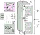
图1为MMC并网变换器的拓扑图;Fig. 1 is the topology diagram of MMC grid-connected converter;
图2为MMC等效电路图;Figure 2 is the MMC equivalent circuit diagram;
其中,图a)为单相等效电路图;图b)为MMC交流等效回路图;图c)为MMC直流等效回路图。Among them, Figure a) is the single-phase equivalent circuit diagram; Figure b) is the MMC AC equivalent circuit diagram; Figure c) is the MMC DC equivalent circuit diagram.
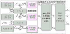
图3为所提基于反馈线性化的直接功率控制框图;Figure 3 is a block diagram of the proposed direct power control based on feedback linearization;
图4为所提MMC并网变换器的直接功率控制框图;Fig. 4 is the direct power control block diagram of the proposed MMC grid-connected converter;
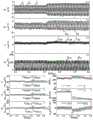
图5为所提直接功率控制在功率阶跃下的仿真结果示意图;Figure 5 is a schematic diagram of the simulation results of the proposed direct power control under a power step;
其中,图a)为输出电流;图b)为桥臂电流;图c)为环流;图d)为桥臂输出电压;图e)为A相电容电压;图f)为有功功率P,无功功率Q及其参考值。Among them, Figure a) is the output current; Figure b) is the bridge arm current; Figure c) is the circulating current; Figure d) is the output voltage of the bridge arm; Figure e) is the phase A capacitor voltage; Figure f) is the active power P, no Power Q and its reference value.
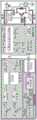
图6为三相MMC实验样机示意图;6 is a schematic diagram of a three-phase MMC experimental prototype;
图7为传统直接功率控制方法下的有功功率阶跃实验波形示意图;Fig. 7 is the schematic diagram of the active power step experiment waveform under the traditional direct power control method;
其中,图a)为输出电流;图b)为A相桥臂电流;图c)为环流;图d)为A相桥臂输出电压;图e)为A相电容电压;图f)为B相电容电压;图g)为C相电容电压;图h)为有功功率P及其参考值;图i)为无功功率Q及其参考值;图j)为有功功率及无功功率跟踪误差。Among them, Figure a) is the output current; Figure b) is the A-phase bridge arm current; Figure c) is the circulating current; Figure d) is the A-phase bridge arm output voltage; Figure e) is the A-phase capacitor voltage; Figure f) is B Phase capacitor voltage; Figure g) is the C-phase capacitor voltage; Figure h) is the active power P and its reference value; Figure i) is the reactive power Q and its reference value; Figure j) is the active power and reactive power tracking error .
图8为所提直接功率控制方法下的有功功率阶跃实验波形示意图;FIG. 8 is a schematic diagram of the active power step experimental waveform under the proposed direct power control method;
其中,图a)为输出电流;图b)为A相桥臂电流;图c)为环流;图d)为A相桥臂输出电压;图e)为A相电容电压;图f)为B相电容电压;图g)为C相电容电压;图h)为有功功率P及其参考值;图i)为无功功率Q及其参考值;图j)为有功功率及无功功率跟踪误差。Among them, Figure a) is the output current; Figure b) is the A-phase bridge arm current; Figure c) is the circulating current; Figure d) is the A-phase bridge arm output voltage; Figure e) is the A-phase capacitor voltage; Figure f) is B Phase capacitor voltage; Figure g) is the C-phase capacitor voltage; Figure h) is the active power P and its reference value; Figure i) is the reactive power Q and its reference value; Figure j) is the active power and reactive power tracking error .
图9为传统直接功率控制方法下的无功功率阶跃实验波形示意图;9 is a schematic diagram of a reactive power step experiment waveform diagram under the traditional direct power control method;
其中,图a)为输出电流;图b)为A相桥臂电流;图c)为环流;图d)为A相桥臂输出电压;图e)为A相电容电压;图f)为B相电容电压;图g)为C相电容电压;图h)为有功功率P及其参考值;图i)为无功功率Q及其参考值;图j)为有功功率及无功功率跟踪误差。Among them, Figure a) is the output current; Figure b) is the A-phase bridge arm current; Figure c) is the circulating current; Figure d) is the A-phase bridge arm output voltage; Figure e) is the A-phase capacitor voltage; Figure f) is B Phase capacitor voltage; Figure g) is the C-phase capacitor voltage; Figure h) is the active power P and its reference value; Figure i) is the reactive power Q and its reference value; Figure j) is the active power and reactive power tracking error .
图10为所提直接功率控制方法下的无功功率阶跃实验波形示意图。Figure 10 is a schematic diagram of the reactive power step experimental waveform under the proposed direct power control method.
其中,图a)为输出电流;图b)为A相桥臂电流;图c)为环流;图d)为A相桥臂输出电压;图e)为A相电容电压;图f)为B相电容电压;图g)为C相电容电压;图h)为有功功率P及其参考值;图i)为无功功率Q及其参考值;图j)为有功功率及无功功率跟踪误差。Among them, Figure a) is the output current; Figure b) is the A-phase bridge arm current; Figure c) is the circulating current; Figure d) is the A-phase bridge arm output voltage; Figure e) is the A-phase capacitor voltage; Figure f) is B Phase capacitor voltage; Figure g) is the C-phase capacitor voltage; Figure h) is the active power P and its reference value; Figure i) is the reactive power Q and its reference value; Figure j) is the active power and reactive power tracking error .
具体实施方式Detailed ways
为使本发明的目的、技术方案和优点更加清楚,下面对本发明实施方式作进一步地详细描述。In order to make the objectives, technical solutions and advantages of the present invention clearer, the embodiments of the present invention are further described in detail below.
为降低系统控制结构的设计难度,保证在有功和无功功率阶跃条件下,多电平变换器具有更快、更好的动态响应,本发明实施例提供了一种基于反馈线性化的多电平变换器直接功率控制方法。In order to reduce the design difficulty of the system control structure and ensure that the multi-level converter has a faster and better dynamic response under the step conditions of active and reactive power, the embodiment of the present invention provides a feedback linearization-based multi-level converter. Level translator direct power control method.
实施例1Example 1
一种基于反馈线性化的多电平变换器直接功率控制方法,该方法包括以下步骤:A method for direct power control of a multilevel converter based on feedback linearization, the method comprises the following steps:
步骤101:根据多电平变换器(MMC)的拓扑结构,构建状态空间模型;Step 101: build a state space model according to the topology of the multilevel converter (MMC);
其中,状态空间模型即为控制对象,应用所提控制方法对控制对象进行线性化,然后进行有功功率、无功功率、环流控制。Among them, the state space model is the control object, and the proposed control method is used to linearize the control object, and then control the active power, reactive power and circulating current.
步骤102:通过反馈线性化技术,将模块化多电平变换器多输入多输出的非线性状态函数模型(即步骤101中的状态空间模型)转化为线性系统;Step 102: Convert the multi-input and multi-output nonlinear state function model of the modular multilevel converter (ie, the state space model in step 101) into a linear system through feedback linearization technology;
步骤103:对于变换后的线性系统,采用比例谐振(Propotional Resonant,PR)控制器对环流进行控制;Step 103: For the transformed linear system, a proportional resonance (PR) controller is used to control the circulating current;
步骤104:对于变换后的线性系统,采用传统的线性PI控制器对有功功率和无功功率进行控制;Step 104: For the transformed linear system, use a traditional linear PI controller to control active power and reactive power;
步骤105:分析变换后线性系统的零动态特性,证明线性系统的稳定性;Step 105: analyze the zero dynamic characteristics of the transformed linear system to prove the stability of the linear system;
步骤106:仿真与实验验证所提直接功率控制方法的有效性。Step 106: Simulation and experiments are performed to verify the effectiveness of the proposed direct power control method.
综上所述,通过上述步骤101-步骤106利用反馈线性化技术将多输入多输出非线性MMC控制系统的状态函数模型转化为线性解耦系统模型,将线性控制器应用于变换后的线性系统模型中,从而降低控制器的设计难度。In summary, through the above steps 101-106, the state function model of the multi-input multi-output nonlinear MMC control system is converted into a linear decoupling system model by using feedback linearization technology, and the linear controller is applied to the transformed linear system. model, thereby reducing the design difficulty of the controller.
实施例2Example 2
下面结合具体的计算公式、附图、实例对上述方案进行进一步地介绍,详见下文描述:The above scheme is further introduced below in conjunction with specific calculation formulas, accompanying drawings and examples, and the details are described below:
步骤201:根据MMC拓扑结构,构建状态空间模型;Step 201: construct a state space model according to the MMC topology structure;
其中,多电平并网变换器的三相拓扑结构如图1所示。其中,MMC的交流端通过滤波电感(等效电感L和等效电阻R)连接到三相交流电网端口。MMC包括三个相同的相单元。每个相单元都包括上桥臂和下桥臂,每个桥臂由N个相同的半桥子模块(HB-SM)组成。上桥臂和下桥臂通过桥臂电感(等效电感Larm和等效电阻Rarm)连接到公共输出端口。此外,MMC的直流端口连接到直流电压源,其电压为Vdc。如图1所示,每个子模块包含两个功率开关、两个反并联的二极管和一个电容。通过控制两个开关的驱动信号,可将每个子模块在主电路中插入或旁路(即模块化多电平换流器子模块中某些绝缘栅双极型晶体管开通,但阀电流不流经子模块直流电容器的运行状态)。假设每个子模块的电容电压为vSM。如果插入子模块,子模块将产生电容电压vSM;另一种则为旁路子模块,则其将产生0电压。Among them, the three-phase topology of the multi-level grid-connected converter is shown in Figure 1. Among them, the AC end of the MMC is connected to the three-phase AC power grid port through a filter inductor (equivalent inductance L and equivalent resistance R). The MMC consists of three identical phase units. Each phase unit includes an upper bridge arm and a lower bridge arm, and each bridge arm is composed of N identical half-bridge sub-modules (HB-SMs). The upper bridge arm and the lower bridge arm are connected to the common output port through bridge arm inductances (equivalent inductance Larm and equivalent resistance Rarm ). In addition, the DC port of the MMC is connected to a DC voltage source whose voltage is Vdc . As shown in Figure 1, each submodule contains two power switches, two anti-parallel diodes, and a capacitor. By controlling the driving signals of the two switches, each sub-module can be inserted or bypassed in the main circuit (that is, some insulated gate bipolar transistors in the sub-module of the modular multilevel converter are turned on, but the valve current does not flow via the operating status of the sub-module DC capacitors). Assume that the capacitor voltage of each submodule is vSM . If a sub-module is inserted, the sub-module will generate a capacitor voltage vSM ; if the other is a bypass sub-module, it will generate 0 voltage.
对于MMC而言,其等效控制电路如图2所示。等效电路可分为交流控制回路和直流控制回路。交流控制回路用于控制有功功率和无功功率,而直流控制回路用于控制环流。对于图2b)中的交流控制回路,其输出功率控制方程可描述为:For MMC, its equivalent control circuit is shown in Figure 2. The equivalent circuit can be divided into AC control loop and DC control loop. The AC control loop is used to control the active and reactive power, while the DC control loop is used to control the circulating current. For the AC control loop in Figure 2b), its output power control equation can be described as:

式中:P和Q分别为MMC的有功功率和无功功率;ugα和ugβ分别为电网电压在α和β坐标系下的分量;iα和iβ分别为输出电流在α和β坐标系下的分量。where P and Q are the active power and reactive power of the MMC, respectively; ugα and ugβ are the components of the grid voltage in the α and β coordinate systems, respectively; iα and iβ are the output current in the α and β coordinates, respectively Quantity under the tie.
其中,有功功率P和无功功率Q的导数可表示为:Among them, the derivative of active power P and reactive power Q can be expressed as:

将基尔霍夫电压定律应用于交流等效控制回路中,其电压和电流应满足如下关系式:Applying Kirchhoff's voltage law to the AC equivalent control loop, its voltage and current should satisfy the following relationship:

式中:uj为变换器输出相电压;ugj为电网相电压;ij为变换器输出电流;iuj和ilj分别为上桥臂和下桥臂桥臂电流;uuj和ulj分别为上桥臂和下桥臂桥臂输出电压;j=a,b,c;Leq和Req分别为交流控制回路中的等效电感和等效电阻。且Leq和Req可表示为:where uj is the output phase voltage of the converter; ugj is the grid phase voltage; ij is the output current of the converter; iuj and ilj are the bridge arm currents of the upper and lower arms,respectively; are the output voltages of the upper bridge arm and the lower bridge arm respectively; j=a, b, c; Leq and Reeq are the equivalent inductance and equivalent resistance in the AC control loop, respectively. And Leq and Req can be expressed as:
Leq=Lac+Larm/2,Req=Rac+Rarm/2 (4)Leq =Lac +Larm /2, Req =Rac +Rarm /2 (4)
其中,Lac为电网侧电感,Rac为电网侧电阻。Among them, Lac is the grid-side inductance, and Rac is the grid-side resistance.
通过clark变换,将等式(3)中的方程转换到αβ坐标系下可表示为:Through clark transformation, the equation in equation (3) can be transformed into the αβ coordinate system and expressed as:

式中:uα和uβ分别为α坐标系和β坐标系下的MMC输出电压。In the formula: uα and uβ are the MMC output voltages in the α coordinate system and the β coordinate system, respectively.
将基尔霍夫电压定律应用于直流等效控制回路中,其电压和电流应满足如下关系式:Applying Kirchhoff's voltage law to the DC equivalent control loop, its voltage and current should satisfy the following relationship:

式中:icirj为MMC三相环流;Vdc为MMC公共直流侧母线电压;ucirj为MMC环流控制电压参考值。Where: icirj is the MMC three-phase circulating current; Vdc is the MMC common DC side bus voltage; ucirj is the MMC circulating current control voltage reference value.
根据式(1)-(6)所述的MMC模型,可列出MMC的状态空间方程。将MMC的状态变量设置为x=[P,Q,iα,iβ,icira,icirb,icirc]T;系统的输出变量设置为y=[P,Q,icira,icirb,icirc]T。根据以上变量设置,将式(6)带入到式(2)中,可将MMC的状态空间方程列写为:According to the MMC model described in equations (1)-(6), the state space equations of the MMC can be listed. Set the state variables of MMC to x=[P,Q,iα ,iβ ,icira ,icirb ,icirc ]T ; set the output variables of the system to y=[P,Q,icira ,icirb , icirc ]T . According to the above variable settings, the equation (6) is brought into the equation (2), and the state space equation of MMC can be written as:

式中:


其中,ugβugα-ugαugβ为矩阵直接相点积在做差,因此差值不为0。Among them, ugβ ugα -ugα ugβ is the difference between the direct dot product of the matrix, so the difference is not 0.
在式(7)所述的状态空间方程中,MMC的状态变量和输入变量之间的关系为非线性系统。因此,为使线性控制策略更好地适应该系统,需利用线性化技术将非线性MMC系统线性化,再使用传统的线性控制策略对系统进行控制。In the state space equation described in equation (7), the relationship between the state variables of the MMC and the input variables is a nonlinear system. Therefore, in order to make the linear control strategy better adapt to the system, the nonlinear MMC system needs to be linearized by the linearization technology, and then the traditional linear control strategy is used to control the system.
步骤202:多输入多输出MMC非线性系统的反馈线性化;Step 202: feedback linearization of the multi-input multi-output MMC nonlinear system;
其中,对式(7)-式(10)中所描述的非线性MMC系统,其输出变量hp(x)关于f(x)和gi(x)的李导数可表示为:Among them, for the nonlinear MMC system described in Equation (7)-Equation (10), the Li derivative of the output variable hp (x) with respect to f(x) and gi (x) can be expressed as:

其中,

对于定义的相对阶数,输出变量hp(x)的rp阶导数可表示为:For a defined relative order, the rp order derivative of the output variable hp (x) can be expressed as:

从中可以看出,输入变量首次出现在hp(x)的rp阶导数中。因此,对于变换后的系统,输入变量γp与输出变量

其中,用于实现将非线性系统线性化的解耦矩阵为:Among them, the decoupling matrix used to realize the linearization of the nonlinear system is:

如果当x=x0时,式(13)适用于所有的指数p=1,2,…,m,则解耦矩阵E对于所有x在x0的领域内非奇异。If equation (13) applies to all exponents p=1,2,...,m when x=x0 , then the decoupling matrix E is non-singular in the field ofx0 for all x.
基于李导数和系统的状态空间函数,对非线性系统进行变换的解耦矩阵E的表达式为:Based on the Lie derivative and the state space function of the system, the expression of the decoupling matrix E for transforming the nonlinear system is:

其中,Lg4、Lg5为沿着向量场gj的李导数符号。Among them, Lg4 , Lg5 are Lie derivative symbols along the vector field gj .
需注意ugα2+ugβ2=Ug2≠0,且桥臂电感Larm≠0,Ug为电网电压幅值。因此,用于进行反馈线性化变换的解耦矩阵E对于所有x在x0的领域内非奇异,即其行列式|E|的值非零。It should be noted that ugα2 +ugβ2 =Ug2 ≠0, and the bridge arm inductance Larm ≠0, Ug is the grid voltage amplitude. Therefore, the decoupling matrix E used to perform the feedback linearization transformation is non-singular in the field of x0 for all x, ie its determinant |E| has a non-zero value.
经过进一步的变换,可将矩阵A(x)表示为:After further transformation, the matrix A(x) can be expressed as:

基于李导数的定义,可推导出非线性MMC系统的相对阶数为r=[1,1,1,1,1]。经变换后,线性系统新的输入变量γ可表示为γ=[dP/dt,dQ/dt,dicira/dt,dicirb/dt,dicirc/dt]T,T为转置。通过对变换后线性系统的新的输入变量实施相应的控制规则,则可实现对系统给定信号的跟踪。Based on the definition of Lie derivatives, it can be deduced that the relative order of the nonlinear MMC system is r=[1,1,1,1,1]. After transformation, the new input variable γ of the linear system can be expressed as γ=[dP/dt, dQ/dt, dicira /dt, dicirb /dt, dicirc /dt]T , where T is the transpose. By implementing the corresponding control rules for the new input variables of the transformed linear system, the tracking of the given signal of the system can be achieved.
定义如式(16)的李导数关于hp(x)的相对阶数为rp,则李导数满足如下约束:The relative order of the Lie derivative with respect to hp (x) is defined as rp as in Eq. (16), then the Lie derivative satisfies the following constraints:

其中,

非线性系统经过线性变换后,线性系统的状态空间方程可以描述为:After the nonlinear system undergoes linear transformation, the state space equation of the linear system can be described as:
u=E-1(x)[γ-A(x)] (17)u=E-1 (x)[γ-A(x)] (17)
式中:u为原非线性系统的输入变量,u=[u1,u2,…,um];γ为变换后新线性系统的输入变量,γ=[γ1,γ2,…,γm],m为输入变量维度。where u is the input variable of the original nonlinear system, u=[u1 , u2 ,…,um ]; γ is the input variable of the new linear system after transformation, γ=[γ1 , γ2 ,…, γm ], where m is the input variable dimension.

其中,


利用式中的反馈线性化技术,可将多输入多输出的非线性MMC系统转化为线性系统。值得注意的是,在该变换后新的线性系统中,状态变量中的P和Q是由电网电压和MMC的输出电流相乘计算得出的。Using the feedback linearization technique in the formula, the nonlinear MMC system with multiple inputs and multiple outputs can be transformed into a linear system. It is worth noting that in the new linear system after the transformation, P and Q in the state variables are calculated by multiplying the grid voltage and the output current of the MMC.
步骤203:环流抑制控制;Step 203: circulating current suppression control;
其中,对于环流控制器,需要对二阶环流进行抑制。因此,采用比例谐振(Propotional Resonant,PR)控制器对环流进行控制,该控制规则可表示为:Among them, for the circulating current controller, it is necessary to suppress the second-order circulating current. Therefore, the proportional resonance (PR) controller is used to control the circulating current, and the control rule can be expressed as:

式中:Kp2和Kr2分别为PR控制器的比例控制器参数和谐振例控制器参数;ω0和ωc分别为电网频率和剪切频率,其中,ωc通常选取为0.01ω0,s为控制传递函数中的变量符号,

步骤204:直接功率控制器设计;Step 204: direct power controller design;
其中,过反馈线性化技术,可将多输入多输出的MMC非线性系统转化为线性系统,从而利用线性控制实现对线性系统的精确控制。如图3所示,所提出的基于反馈线性化的直接功率控制主要分为三个环节,目标跟踪误差计算环节,线性控制环节,反馈线性化环节。首先,对系统的给定控制目标与实际测量做差,得出各控制环节的跟踪误差;其次,利用线性控制器,对经过线性化的新系统的输入变量进行求解;最后,利用反馈线性化技术,求解出原MMC非线性系统的输入变量,并将控制信号传递给MMC并网变换器。Among them, the over-feedback linearization technology can convert the multi-input multi-output MMC nonlinear system into a linear system, so as to use the linear control to realize the precise control of the linear system. As shown in Figure 3, the proposed direct power control based on feedback linearization is mainly divided into three links, the target tracking error calculation link, the linear control link, and the feedback linearization link. First, the difference between the given control target of the system and the actual measurement is made to obtain the tracking error of each control link; secondly, the linear controller is used to solve the input variables of the new linearized system; finally, the feedback linearization is used technology, solve the input variables of the original MMC nonlinear system, and transmit the control signal to the MMC grid-connected converter.
所研究的系统经过反馈线性化变换技术进行线性化变换后,新系统的各相对阶数之和为5,而原始系统的状态变量数为7。After the system under study is linearized by the feedback linearization technology, the sum of the relative orders of the new system is 5, while the number of state variables of the original system is 7.
根据图3中所提出的基于反馈线性化的直接功率控制结构,传统的线性控制规则可被应用于控制经过线性变换后的新系统中的变量γ。MMC并网变换器在与电网进行功率传输交换的过程中,有功功率和无功功率参考值通常为直流分量。因此,将采用传统的PI控制,对系统的有功和无功功率给定进行控制。此外,主要针对进行远距离直流输电的应用场合。在该应用场合中,对于MMC的控制主要关注系统级功率传输,环流参考值通常设置为直流分量,即i*cir=idc/3。According to the proposed direct power control structure based on feedback linearization in Fig. 3, traditional linear control rules can be applied to control the variable γ in the new system after linear transformation. In the process of power transmission and exchange between the MMC grid-connected converter and the grid, the reference values of active power and reactive power are usually DC components. Therefore, the traditional PI control will be used to control the active and reactive power of the system. In addition, it is mainly aimed at the application of long-distance DC power transmission. In this application, the control of the MMC mainly focuses on system-level power transfer, and the circulating current reference value is usually set to the DC component, ie i*cir =idc /3.
经过线性变换后,新的线性系统的输入变量γ1和γ2的控制规则可表示为:After linear transformation, the control rules for the input variablesγ1 and γ2of the new linear system can be expressed as:

式中:Kp1和Ki1分别为PI控制器的比例控制器参数和积分例控制器参数,

所提出的基于反馈线性化的直接功率控制方法如图4所示。图中,vSMujx和vSMljx为测得上桥臂和下桥臂的电容电压,下标j与x分别指示相序与子模块序号,j=a,b,c,且x=1,2,…N;nuj和nlj是上桥臂和下桥臂归一化的调制系数。如图4所示,所提出的基于反馈线性化的直接功率控制框图包含三部分,分别为有功与无功功率控制,环流控制与调制方法。其中,直接功率控制算法中的有功与无功功率控制和环流控制部分分别提供输出电压参考值uj和ucirj。The proposed direct power control method based on feedback linearization is shown in Fig. 4. In the figure, vSMujx and vSMljx are the measured capacitance voltages of the upper and lower bridge arms, the subscripts j and x indicate the phase sequence and the sub-module serial number respectively, j=a, b, c, and x=1,2 ,...N; nuj and nlj are the normalized modulation coefficients of the upper and lower arms. As shown in Figure 4, the proposed direct power control block diagram based on feedback linearization consists of three parts, namely active and reactive power control, circulating current control and modulation method. Among them, the active and reactive power control and circulating current control parts of the direct power control algorithm provide output voltage reference values uj and ucirj , respectively.
所得出的电压参考值uj和环流控制电压参考值ucirj将被用于调制方法中计算每个桥臂的输出电压参考值信号。每个桥臂的输出电压参考值可表示为:The obtained voltage reference value uj and the circulating current control voltage reference value ucirj will be used in the modulation method to calculate the output voltage reference value signal of each bridge arm. The output voltage reference value of each bridge arm can be expressed as:

此外,载波移相脉宽调制(Carrier-Phase-Shift Pulse Width Modulation,CPS-PWM)方法被用于所提出的直接功率控制算法中。在将各桥臂的电压参考值信号归一化后,通过桥臂内各个子模块间调制信号的调整,可实现子模块间的电容电压均衡。其各个子模块的最终调制信号可表示为:Furthermore, the Carrier-Phase-Shift Pulse Width Modulation (CPS-PWM) method is used in the proposed direct power control algorithm. After the voltage reference value signal of each bridge arm is normalized, the capacitor voltage balance among the submodules can be realized by adjusting the modulation signal among the respective submodules in the bridge arm. The final modulated signal of each sub-module can be expressed as:

其中,nujx、nljx为上、下桥臂各子模块的调制系数,nuj、nlj为上、下桥臂归一化的调制系数,Kpind为调制系数,vSMujx和vSMljx为测得上桥臂和下桥臂的电容电压,

由此,可实现MMC并网变换器基于反馈线性化的直接功率控制策略。Thus, the direct power control strategy based on feedback linearization of the MMC grid-connected converter can be realized.
步骤205:分析变换后线性系统的零动态特性,证明线性系统的稳定性;Step 205: analyze the zero dynamic characteristics of the transformed linear system to prove the stability of the linear system;
其中,非线性MMC经过反馈线性化变换后新系统的相对阶数为r1+r2+r3+r4+r5=5,其小于MMC原系统的输入变量的个数7。其中,只有5个变量被完全观测,另两个状态变量无法被完全观测。此时,输出变量中未被观测的两个变量可能引起系统的不稳定。因此,有必要对系统的零动态特性进行检验,以保证反馈线性化系统的稳定性。The relative order of the new system after nonlinear MMC is transformed by feedback linearization is r1 +r2 +r3 +r4 +r5 =5, which is less than the number of input variables 7 of the original MMC system. Among them, only 5 variables are fully observed, and the other two state variables cannot be fully observed. At this time, the unobserved two variables in the output variables may cause the instability of the system. Therefore, it is necessary to check the zero dynamic characteristics of the system to ensure the stability of the feedback linearized system.
状态变量P,Q,icira,icirb,和icirc已经被线性化。因此,只需要校验剩余的两个状态变量iα和iβ的零动态。基于公式(21),状态变量iα和iβ可被表示为关于状态变量P和Q的形式。The state variables P, Q, icira , icirb , and icirc have been linearized. Therefore, it is only necessary to check the zero dynamics of the remaining two state variables iα and iβ . Based on Equation (21), the state variables iα and iβ can be expressed in terms of the state variables P and Q.

其中,y1、y2为输出变量P和Q;Ug为电网电压幅值。Among them, y1 and y2 are output variables P and Q; Ug is the grid voltage amplitude.
进一步,iα和iβ的导数可以表示为:Further, the derivatives of iα and iβ can be expressed as:

其中,


通常情况下,为验证系统的零动态稳定性,可采用李雅普诺夫函数或对常用与线性系统稳定性分析的改进分析理论。一般情况下,采用李雅普诺夫函数对控制系统进行稳定性分析需要恰当的选择中间变量,在设计上相对难于实现。因此,基于传统线性系统的稳定性分析理论改进的零动态稳定性分析理论,对反馈线性化变换系统的零动态稳定性进行分析。根据文献中的稳定性分析方法可知,对于两个输出变量y1和y2,当其导数为稳定且有界的函数时,系统的零动态稳定性主要取决于系统传递函数的零点。当系统传递函数的零点全部位于左半平面时,即Re{Zreos}≤0时,则受控系统是最小相位系统,系统的零动态稳定性也相应地得到保证。基于式(18),系统状态变量(iα和iβ)的零点都为0(Zero(iα)=0;Zero(iβ)=0)。因此,受控系统是最小相位系统,而系统的零动态稳定性也得到保证。Usually, in order to verify the zero dynamic stability of the system, the Lyapunov function or an improved analytical theory for the stability analysis of common and linear systems can be used. In general, the use of Lyapunov function to analyze the stability of the control system requires appropriate selection of intermediate variables, which is relatively difficult to achieve in design. Therefore, based on the improved zero dynamic stability analysis theory of the traditional linear system stability analysis theory, the zero dynamic stability of the feedback linearized transformation system is analyzed. According to the stability analysis method in the literature, for two output variables y1 and y2 , when their derivatives are stable and bounded functions, the zero dynamic stability of the system mainly depends on the zero point of the system transfer function. When the zero points of the system transfer function are all located in the left half plane, that is, when Re{Zreos}≤0, the controlled system is a minimum phase system, and the zero dynamic stability of the system is also guaranteed accordingly. Based on equation (18), the zero points of the system state variables (iα and iβ ) are both 0 (Zero(iα )=0; Zero(iβ )=0). Therefore, the controlled system is a minimum phase system, and the zero dynamic stability of the system is also guaranteed.
步骤206:仿真与实验验证所提直接功率控制方法的有效性;Step 206: simulation and experiment to verify the effectiveness of the proposed direct power control method;
其中,为验证所提出基于反馈线性化的直接功率控制技术的有效性,在仿真环境中建立了MMC系统的三相仿真模型,以验证所提算法的有效性。仿真参数如表1所示。Among them, in order to verify the effectiveness of the proposed direct power control technology based on feedback linearization, a three-phase simulation model of the MMC system is established in the simulation environment to verify the effectiveness of the proposed algorithm. The simulation parameters are shown in Table 1.
表1仿真及实验参数Table 1 Simulation and experimental parameters

为了验证所提出的基于反馈线性化的直接功率控制方法的有效性,在图5中给出了功率阶跃运行工况下的仿真结果。在仿真过程中,在0.5s之前,有功功率和无功功率设置为0.67MW和-0.67MVar。在0.5s时,有功功率参考值从0.67MW增加到1.34MW。然后,在0.7s的时刻,无功功率从-0.67MVar增加到-1.34MVar。To verify the effectiveness of the proposed direct power control method based on feedback linearization, the simulation results under the power step operating condition are presented in Fig. 5. During the simulation, the active power and reactive power are set to 0.67MW and -0.67MVar before 0.5s. At 0.5s, the active power reference value increases from 0.67MW to 1.34MW. Then, at the moment of 0.7s, the reactive power increases from -0.67MVar to -1.34MVar.
如图5a)所示,在0.5s之前,输出电流的幅值约为141A,其中有功电流的幅值应约为100A,而无功电流的幅值应约为100A。从0.5s时刻开始,输出电流的幅值从141A增加到大约223A,其中有功电流的幅值应该约为200A,而无功电流的幅值应该约为100A。在0.7s时刻,输出电流的幅值从232A增加到大约283A,其中有功电流的幅值应该约为200A,而无功电流的幅值应该增至约为200A。A相中的桥臂电流如图5b)所示。在0.5s之前,桥臂电流的幅值约为70.7A,直流偏移约为22.5A。从0.5s时刻开始,桥臂电流的幅值从70.7A增至约116A,并且存在约44.9A的直流偏移电流。在0.7s时,桥臂电流的幅值从116A增加到大约141A,直流偏移量约为44.9A。三相环流波形如图5c)所示。在0.5s之前,环流约为22.5A,其数值与桥臂电流中的直流偏移分量相同。在0.5s时,由于有功功率阶跃,环流从22.5A增加到约44.9A。然后,在无功功率阶跃情况下,在0.7s时,环流保持在约44.9A。在整个工作过程中,环流的数值与桥臂电流中的直流偏移分量相同。A相的桥臂输出电压如图5d)所示,其数值在0V至约10kV之间变化。A相的电容电压如图5e)所示。在整个工作作过程中,电容电压的平均值保持在约1kV,与额定值相同。在0.5s时,电容电压纹波随有功功率的阶跃而增加。在0.7s时,电容电压纹波随着无功功率的阶跃而再次增加。然而,电容电压的平均值始终维持在在额定值附近,并保持稳定。图5f)中给出了有功功率P,无功功率Q及其参考值。从图中可以看出,在0.5之前,有功功率和无功功率分别约为0.67MW和-0.67MVar。在0.5s时,有功功率从0.67MW增加到1.34MW,而无功功率保持在-0.67MVar。然后,在0.7s时刻,无功功率从-0.67MVar增加到-1.34MVar,而有功功率保持在大约1.34MW。在整个运行过程中,有功功率和无功功率可以准确地跟踪其参考值,从而验证了所提出的基于反馈线性化的直接功率控制方法的有效性。As shown in Figure 5a), before 0.5s, the amplitude of the output current is about 141A, in which the amplitude of the active current should be about 100A, and the amplitude of the reactive current should be about 100A. From 0.5s, the magnitude of the output current increases from 141A to about 223A, where the magnitude of the active current should be about 200A, and the magnitude of the reactive current should be about 100A. At 0.7s, the magnitude of the output current increases from 232A to about 283A, where the magnitude of the active current should be about 200A and the magnitude of the reactive current should increase to about 200A. The bridge arm current in phase A is shown in Fig. 5b). Before 0.5s, the amplitude of the bridge arm current is about 70.7A, and the DC offset is about 22.5A. From the moment of 0.5s, the amplitude of the bridge arm current increases from 70.7A to about 116A, and there is a DC offset current of about 44.9A. At 0.7s, the amplitude of the bridge arm current increases from 116A to about 141A, and the DC offset is about 44.9A. The three-phase circulating current waveform is shown in Fig. 5c). Before 0.5s, the circulating current is about 22.5A, which is the same value as the DC offset component in the bridge arm current. At 0.5s, the circulating current increases from 22.5A to about 44.9A due to the active power step. Then, in the reactive power step case, at 0.7s, the circulating current remains at about 44.9A. During the entire operation, the value of the circulating current is the same as the DC offset component in the bridge arm current. The output voltage of the bridge arm of phase A is shown in Fig. 5d), and its value varies from 0V to about 10kV. The capacitor voltage of phase A is shown in Fig. 5e). During the entire operation, the average value of the capacitor voltage remains at about 1kV, which is the same as the rated value. At 0.5s, the capacitor voltage ripple increases with the step of active power. At 0.7s, the capacitor voltage ripple increases again with the reactive power step. However, the average value of the capacitor voltage remains around the rated value and remains stable. Active power P, reactive power Q and their reference values are given in Fig. 5f). As can be seen from the figure, before 0.5, the active power and reactive power are about 0.67MW and -0.67MVar, respectively. At 0.5s, the active power increases from 0.67MW to 1.34MW, while the reactive power remains at -0.67MVar. Then, at 0.7s, the reactive power increases from -0.67MVar to -1.34MVar, while the active power remains at about 1.34MW. During the whole operation, the active and reactive powers can track their reference values accurately, which verifies the effectiveness of the proposed direct power control method based on feedback linearization.
为了进一步验证所提出基于反馈线性化的直接功率控制方法的有效性和动态响应,通过实验室三相MMC样机进行了实验。所采用的三相MMC样机如图6所示。实验参数列于表1中。MMC的交流输出端连接到三相可编程交流电源,MMC的直流侧则连接到直流电源。DSpace 1006被用作为中央控制器,PSS15S92F6-AG(智能电源模块)用作功率模块的开关器件。实验结果通过上位机采集的波形给出。To further verify the effectiveness and dynamic response of the proposed direct power control method based on feedback linearization, experiments were carried out on a laboratory three-phase MMC prototype. The three-phase MMC prototype used is shown in Figure 6. The experimental parameters are listed in Table 1. The AC output of the MMC is connected to a three-phase programmable AC power supply, and the DC side of the MMC is connected to the DC power supply. DSpace 1006 is used as the central controller and PSS15S92F6-AG (Intelligent Power Module) is used as the switching device of the power module. The experimental results are given by the waveform collected by the host computer.
为了验证所提出的基于反馈线性化的直接功率控制方法在有功功率阶跃运行条件下的动态性能,将所提出的方法与传统常规直接功率控制方法[23]的实验进行对比,实验结果分别如图7和图8所示。在该运行过程中,有功功率和无功功率分别设置为60W和0Var。然后,当有功功率发生阶跃时,有功功率从60W增加到120W。In order to verify the dynamic performance of the proposed direct power control method based on feedback linearization under active power step operation conditions, the proposed method is compared with the experiments of the traditional conventional direct power control method[23] . The experimental results are as follows: 7 and 8. During this operation, the active power and reactive power were set to 60W and 0Var, respectively. Then, when the active power is stepped, the active power is increased from 60W to 120W.
如图7a)和图8a)所示,在两种直接功率控制方式下,在正常运行工况下,输出电流的幅值均约为1A;当有功功率阶跃发生时,两种控制方式下的输出电流的幅度均从1A增加至约2A。然而,从图中可以看出,采用所提出的基于反馈线性化的直接功率控制方法下,MMC并网变换器的输出电流具有更快的响应速度。图7b)和图8b)中给出的A相上桥臂和下桥臂的输出桥电流。从中可以看出,在正常运行工况时,两种控制方式下的幅值皆约为0.5A。当发生有功功率阶跃时,幅值增加到约1A。MMC并网变换器的环流波形如图7c)和图8c)所示。图中表明,在正常运行工况时,两种控制方式下的环流均保持稳定,且二倍频环流均被较好地抑制。此外,当有功功率阶跃发生时,环流保持稳定并略有增加,且二倍频环流均被较好地抑制。图7d)和图8d)中给出了A相相应的桥臂输出电压波形。相各桥臂中每个子模块的电容电压波形分别如图7e)至g)和图8e)至g)所示,其其平均值被调节在额定30V左右。对比图7h)和图8h)中有功功率P及其参考值P*,可以看出,采用所提出的基于反馈线性化的直接功率控制方法,在有功功率发生阶跃时,系统具有更好的动态响应,且有功功率的跟踪误差较小功率。比较图7i)和图8i)中的无功功率Q及其参考值Q*,可以看出,采用所提出的基于反馈线性化的直接功率控制方法,在有功功率发生阶跃时,系统具有更好的动态响应,且无功功率的跟踪误差较小功率。有功功率和无功功率的跟踪误差分别示于图7j)和图8j)中。从中可以看出,相较于传统直接功率控制方法,采用所提出的基于反馈线性化的直接功率控制方法时,MMC并网变换器在有功功率和无功功率控制方面具有更好的动态性能。As shown in Fig. 7a) and Fig. 8a), under the two direct power control methods, under normal operating conditions, the amplitude of the output current is about 1A; when the active power step occurs, under the two control methods The magnitudes of the output currents were increased from 1A to about 2A. However, it can be seen from the figure that with the proposed direct power control method based on feedback linearization, the output current of the MMC grid-connected converter has a faster response speed. The output bridge currents for the upper and lower legs of phase A are given in Figures 7b) and 8b). It can be seen that in normal operating conditions, the amplitudes of the two control modes are both about 0.5A. When an active power step occurs, the amplitude increases to about 1A. The circulating current waveforms of the MMC grid-connected converter are shown in Fig. 7c) and Fig. 8c). The figure shows that, under normal operating conditions, the circulation under the two control modes remains stable, and the double-frequency circulation is well suppressed. In addition, when the active power step occurs, the circulating current remains stable and increases slightly, and the double-frequency circulating current is well suppressed. Figures 7d) and 8d) show the corresponding bridge arm output voltage waveforms of phase A. The capacitor voltage waveforms of each sub-module in each bridge arm of the phase are shown in Figures 7e) to g) and Figures 8e) to g), respectively, and the average value thereof is adjusted to be around the rated value of 30V. Comparing the active power P and its reference value P* in Fig. 7h) and Fig. 8h), it can be seen that with the proposed direct power control method based on feedback linearization, when the active power has a step, the system has better performance. Dynamic response, and the tracking error of active power is small. Comparing the reactive power Q and its reference value Q* in Fig. 7i) and Fig. 8i), it can be seen that with the proposed direct power control method based on feedback linearization, the system has more power when there is a step in the active power. Good dynamic response, and the tracking error of reactive power is small. The tracking errors for active power and reactive power are shown in Fig. 7j) and Fig. 8j), respectively. It can be seen that compared with the traditional direct power control method, when the proposed direct power control method based on feedback linearization is adopted, the MMC grid-connected converter has better dynamic performance in active power and reactive power control.
为了验证所提出的基于反馈线性化的直接功率控制方法在无功功率阶跃运行条件下的动态性能,将所提出的方法与传统常规直接功率控制方法[23]的实验进行对比,实验结果分别如图9和图10所示。在该运行过程中,有功功率和无功功率分别设置为为120W和0Var。然后,当无功功率发生阶跃时,有功功率从0Var增加到120Var。In order to verify the dynamic performance of the proposed direct power control method based on feedback linearization under reactive power step operating conditions, the proposed method is compared with the experiments of the traditional conventional direct power control method[23] . As shown in Figure 9 and Figure 10. During this operation, the active power and reactive power are set to 120W and 0Var, respectively. Then, when the reactive power is stepped, the active power is increased from 0Var to 120Var.
如图9a)和图10a)所示,在两种直接功率控制方式下,在正常运行工况下,输出电流的幅值均约为2A;当无功功率阶跃发生时,两种控制方式下的输出电流的幅度均从2A增加至约2.82A。然而,从图中可以看出,采用所提出的基于反馈线性化的直接功率控制方法下,MMC并网变换器的输出电流具有更快的响应速度。图9b)和图10b)中给出的A相上桥臂和下桥臂的输出桥电流。从中可以看出,在正常运行工况时,两种控制方式下的幅值皆约为1A。当发生无功功率阶跃时,幅值增加到约1.41A。MMC并网变换器的环流波形如图9c)和图10c)所示。图中表明,在运行过程中,两种控制方式下的环流均保持稳定,且二倍频环流均被较好地抑制。图9d)和图10d)中给出了A相相应的桥臂输出电压波形。相各桥臂中每个子模块的电容电压波形分别如图9e)至g)和图10e)至g)所示,其其平均值被调节在额定30V左右。对比图9h)和图10h)中有功功率P及其参考值P*,可以看出,采用所提出的基于反馈线性化的直接功率控制方法,在无功功率发生阶跃时,系统具有更好的动态响应,且有功功率的跟踪误差较小功率。比较图9i)和图10i)中的无功功率Q及其参考值Q*,可以看出,采用所提出的基于反馈线性化的直接功率控制方法,在无功功率发生阶跃时,系统具有更好的动态响应,且无功功率的跟踪误差较小功率。有功功率和无功功率的跟踪误差分别示于图9j)和图10j)中。从中可以看出,相较于传统直接功率控制方法,采用所提出的基于反馈线性化的直接功率控制方法时,MMC并网变换器在有功功率和无功功率控制方面具有更好的动态性能。As shown in Figure 9a) and Figure 10a), under the two direct power control methods, under normal operating conditions, the amplitude of the output current is about 2A; when the reactive power step occurs, the two control methods The magnitudes of the output currents under both increased from 2A to about 2.82A. However, it can be seen from the figure that with the proposed direct power control method based on feedback linearization, the output current of the MMC grid-connected converter has a faster response speed. Figure 9b) and Figure 10b) The output bridge currents for the upper and lower legs of phase A are given. It can be seen from this that in normal operating conditions, the amplitudes of both control modes are about 1A. When a reactive power step occurs, the amplitude increases to about 1.41A. The circulating current waveforms of the MMC grid-connected converter are shown in Fig. 9c) and Fig. 10c). The figure shows that in the process of operation, the circulation under the two control modes remains stable, and the double-frequency circulation is well suppressed. Figure 9d) and Figure 10d) show the corresponding bridge arm output voltage waveforms of phase A. The capacitor voltage waveforms of each sub-module in each bridge arm of the phase are shown in Figures 9e) to g) and Figures 10e) to g), respectively, and the average value thereof is adjusted to be around the rated value of 30V. Comparing the active power P and its reference value P* in Fig. 9h) and Fig. 10h), it can be seen that with the proposed direct power control method based on feedback linearization, the system has better performance when the reactive power has a step. dynamic response, and the tracking error of active power is small. Comparing the reactive power Q and its reference value Q* in Fig. 9i) and Fig. 10i), it can be seen that with the proposed direct power control method based on feedback linearization, when the reactive power has a step, the system has Better dynamic response and less tracking error for reactive power. The tracking errors for active power and reactive power are shown in Fig. 9j) and Fig. 10j), respectively. It can be seen that compared with the traditional direct power control method, when the proposed direct power control method based on feedback linearization is adopted, the MMC grid-connected converter has better dynamic performance in active power and reactive power control.
综上所述,可以得出基于反馈线性化的模块化多电平变换器直接功率控制方法的优点:In summary, the advantages of the feedback linearization-based direct power control method for modular multilevel converters can be drawn:
1)通过反馈线性化技术,可将多输入多输出的MMC非线性系统转化为线性系统,有助于利用线性控制实现对线性系统的精确控制;1) Through the feedback linearization technology, the multi-input and multi-output MMC nonlinear system can be converted into a linear system, which is helpful to realize the precise control of the linear system by using the linear control;
2)与传统的模块化多电平变换器所采用的线性解耦直接功率控制方法相比,本发明所提基于反馈线性化的直接功率控制方法降低了系统控制结构的设计难度,且控制效果更加精确;2) Compared with the linear decoupling direct power control method adopted by the traditional modular multi-level converter, the direct power control method based on feedback linearization proposed by the present invention reduces the design difficulty of the system control structure, and the control effect is improved. more precise;
3)本发明所提出的控制方法,即使在有功和无功功率阶跃条件下,模块化多电平变换器具有更快,更好的动态响应。3) With the control method proposed by the present invention, the modular multilevel converter has faster and better dynamic response even under the step condition of active and reactive power.
一种多电平变换器直接功率控制装置,该装置包括:A device for direct power control of a multilevel converter, the device comprising:
转换模块,用于通过反馈线性化技术,将多电平变换器多输入多输出的非线性状态函数模型转化为线性系统;The conversion module is used to convert the multi-input and multi-output nonlinear state function model of the multi-level converter into a linear system through feedback linearization technology;
环流控制模块,用于对于变换后的线性系统,采用比例谐振控制器对环流进行控制;The circulating current control module is used to control the circulating current with a proportional resonance controller for the transformed linear system;
有功功率和无功功率控制模块,用于对于变换后的线性系统,采用传统的线性PI控制器对有功功率和无功功率进行控制;The active power and reactive power control module is used to control the active power and reactive power by using the traditional linear PI controller for the transformed linear system;
分析模块,用于分析变换后线性系统的零动态特性,证明线性系统的稳定性。The analysis module is used to analyze the zero dynamic characteristics of the transformed linear system and prove the stability of the linear system.
这里需要指出的是,以上实施例中的装置描述是与上述方法实施例描述相对应的,本发明实施例在此不做赘述。It should be pointed out here that the device descriptions in the above embodiments correspond to the descriptions of the above method embodiments, which are not described in detail in this embodiment of the present invention.
上述各个模块、单元的执行主体可以是计算机、单片机、微控制器等具有计算功能的器件,具体实现时,本发明实施例对执行主体不做限制,根据实际应用中的需要进行选择。The execution bodies of the above-mentioned modules and units may be devices with computing functions such as computers, single-chip microcomputers, and microcontrollers. During specific implementation, the embodiments of the present invention do not limit the execution bodies, and are selected according to actual application needs.
本发明实施例对各器件的型号除做特殊说明的以外,其他器件的型号不做限制,只要能完成上述功能的器件均可。In the embodiment of the present invention, the models of each device are not limited unless otherwise specified, as long as the device can perform the above functions.
本领域技术人员可以理解附图只是一个优选实施例的示意图,上述本发明实施例序号仅仅为了描述,不代表实施例的优劣。Those skilled in the art can understand that the accompanying drawing is only a schematic diagram of a preferred embodiment, and the above-mentioned serial numbers of the embodiments of the present invention are only for description, and do not represent the advantages or disadvantages of the embodiments.
以上所述仅为本发明的较佳实施例,并不用以限制本发明,凡在本发明的精神和原则之内,所作的任何修改、等同替换、改进等,均应包含在本发明的保护范围之内。The above descriptions are only preferred embodiments of the present invention, and are not intended to limit the present invention. Any modification, equivalent replacement, improvement, etc. made within the spirit and principle of the present invention shall be included in the protection of the present invention. within the range.
Claims (5)
Translated fromChinese


Priority Applications (1)
| Application Number | Priority Date | Filing Date | Title |
|---|---|---|---|
| CN202110265402.4ACN113036797B (en) | 2021-03-11 | 2021-03-11 | Multilevel converter direct power control method and device |
Applications Claiming Priority (1)
| Application Number | Priority Date | Filing Date | Title |
|---|---|---|---|
| CN202110265402.4ACN113036797B (en) | 2021-03-11 | 2021-03-11 | Multilevel converter direct power control method and device |
Publications (2)
| Publication Number | Publication Date |
|---|---|
| CN113036797Atrue CN113036797A (en) | 2021-06-25 |
| CN113036797B CN113036797B (en) | 2022-07-15 |
Family
ID=76469611
Family Applications (1)
| Application Number | Title | Priority Date | Filing Date |
|---|---|---|---|
| CN202110265402.4AActiveCN113036797B (en) | 2021-03-11 | 2021-03-11 | Multilevel converter direct power control method and device |
Country Status (1)
| Country | Link |
|---|---|
| CN (1) | CN113036797B (en) |
Cited By (4)
| Publication number | Priority date | Publication date | Assignee | Title |
|---|---|---|---|---|
| CN113541477A (en)* | 2021-07-21 | 2021-10-22 | 深圳职业技术学院 | A Boost Modular DC-DC Converter for HVDC Transmission Systems |
| CN113630006A (en)* | 2021-08-18 | 2021-11-09 | 南方电网科学研究院有限责任公司 | Nonlinear control method for direct current converter |
| CN113809928A (en)* | 2021-09-16 | 2021-12-17 | 西安交通大学 | DAB converter power control method, medium and equipment based on power feedforward |
| CN118675397A (en)* | 2024-07-03 | 2024-09-20 | 天津大学 | Teaching platform based on multi-level converter system and application method thereof |
Citations (5)
| Publication number | Priority date | Publication date | Assignee | Title |
|---|---|---|---|---|
| CN102882383A (en)* | 2012-09-28 | 2013-01-16 | 无锡清源电气科技有限公司 | Direct power control method of modular multilevel wind power converter |
| CN108667284A (en)* | 2018-05-21 | 2018-10-16 | 武汉科技大学 | A Method for Circulating Current Suppression of Modular Multilevel Converter |
| CN108964104A (en)* | 2017-05-18 | 2018-12-07 | 华北电力大学(保定) | A kind of MMC circulation inhibition method based on sliding formwork control |
| CN110504853A (en)* | 2018-05-18 | 2019-11-26 | 南京理工大学 | Improved circulation control method based on flexible direct current transmission |
| CN112436520A (en)* | 2020-11-27 | 2021-03-02 | 上海电力大学 | Alternating current power spring feedback linearization decoupling control method |
- 2021
- 2021-03-11CNCN202110265402.4Apatent/CN113036797B/enactiveActive
Patent Citations (5)
| Publication number | Priority date | Publication date | Assignee | Title |
|---|---|---|---|---|
| CN102882383A (en)* | 2012-09-28 | 2013-01-16 | 无锡清源电气科技有限公司 | Direct power control method of modular multilevel wind power converter |
| CN108964104A (en)* | 2017-05-18 | 2018-12-07 | 华北电力大学(保定) | A kind of MMC circulation inhibition method based on sliding formwork control |
| CN110504853A (en)* | 2018-05-18 | 2019-11-26 | 南京理工大学 | Improved circulation control method based on flexible direct current transmission |
| CN108667284A (en)* | 2018-05-21 | 2018-10-16 | 武汉科技大学 | A Method for Circulating Current Suppression of Modular Multilevel Converter |
| CN112436520A (en)* | 2020-11-27 | 2021-03-02 | 上海电力大学 | Alternating current power spring feedback linearization decoupling control method |
Non-Patent Citations (1)
| Title |
|---|
| SHUNFENG YANG ET AL.: "Feedback Linearization-Based Current Control Strategy for Modular Multilevel Converters", 《IEEE TRANSACTIONS ON POWER ELECTRONICS》* |
Cited By (7)
| Publication number | Priority date | Publication date | Assignee | Title |
|---|---|---|---|---|
| CN113541477A (en)* | 2021-07-21 | 2021-10-22 | 深圳职业技术学院 | A Boost Modular DC-DC Converter for HVDC Transmission Systems |
| CN113541477B (en)* | 2021-07-21 | 2022-08-02 | 深圳职业技术学院 | Boosting modular DC-DC converter for high-voltage direct-current power transmission system |
| CN113630006A (en)* | 2021-08-18 | 2021-11-09 | 南方电网科学研究院有限责任公司 | Nonlinear control method for direct current converter |
| CN113630006B (en)* | 2021-08-18 | 2022-04-19 | 南方电网科学研究院有限责任公司 | Nonlinear control method for direct current converter |
| CN113809928A (en)* | 2021-09-16 | 2021-12-17 | 西安交通大学 | DAB converter power control method, medium and equipment based on power feedforward |
| CN113809928B (en)* | 2021-09-16 | 2024-03-22 | 西安交通大学 | DAB converter power control method, medium and device based on power feedforward |
| CN118675397A (en)* | 2024-07-03 | 2024-09-20 | 天津大学 | Teaching platform based on multi-level converter system and application method thereof |
Also Published As
| Publication number | Publication date |
|---|---|
| CN113036797B (en) | 2022-07-15 |
Similar Documents
| Publication | Publication Date | Title |
|---|---|---|
| CN113036797B (en) | Multilevel converter direct power control method and device | |
| CN103683288B (en) | Parallel Active Filter Based on Modular Multilevel Converter and Its Control Method | |
| CN108280271A (en) | THE UPFC equivalent modeling method based on switch periods average principle | |
| CN111262465B (en) | Passive control method for modularized multi-level matrix converter | |
| CN101814853A (en) | Control method of modularization multi-level converter based on equivalent circuit model | |
| CN111293894A (en) | Capacitor voltage balance control method for modular multilevel matrix converter | |
| CN106026737B (en) | A kind of three-level current transformer compound circulation inhibition method in parallel | |
| CN102751720A (en) | Flexible high-voltage direct-current (HVDC) load flow computational model and computational method thereof | |
| CN113690889A (en) | Power harmonic treatment method for improving active power filter by novel multi-level converter | |
| CN109921424A (en) | The passive control method of point type three-phase four-wire system shunt active power filter in capacitor | |
| CN112087158A (en) | Open-loop circulating current restraining method of modular multilevel converter | |
| CN109586596B (en) | A fuzzy passive control design method of EMU rectifier based on EL model | |
| CN117763793A (en) | PSCAD/EMTDC-based simulation modeling method for reactive compensation coordination controller of flexible distribution transformer | |
| Vipin et al. | An online-optimization-based high-frequency link control of an mmc-driven power electronic transformer for wind-energy systems | |
| Wang et al. | Study on an improve finite‐control‐set‐model predictive control (FCS‐MPC) strategy for a T‐type rectifier with direct power control strategy | |
| CN110460058A (en) | A Control Method of Nonlinear Unified Power Flow Controller | |
| CN115765508A (en) | Equivalent Space Vector Model Predictive Control Method for Modular Multilevel Converter | |
| CN106099937A (en) | A kind of Research on Unified Power Quality Conditioner and control method thereof | |
| CN116545014A (en) | Active power filter based on first-order PI-synovial membrane control and filtering method | |
| CN108964104A (en) | A kind of MMC circulation inhibition method based on sliding formwork control | |
| Wang et al. | Unified power control strategy for new generation poloidal field power supply | |
| CN102694385A (en) | Phase current balancing and amplitude-limiting method for asymmetrical compensation of line current of distribution static compensator (D-STATCOM) | |
| Zabihinejad et al. | Design of direct power controller for a high power neutral point clamped converter using real time simulator | |
| Wang et al. | High-gain sparse three-level indirect matrix converter and its modulation strategy | |
| Gao et al. | A Modified PBC Controller for LCL‐Filtered Grid‐Tied DC/AC Inverter With Enhanced Control Performance |
Legal Events
| Date | Code | Title | Description |
|---|---|---|---|
| PB01 | Publication | ||
| PB01 | Publication | ||
| SE01 | Entry into force of request for substantive examination | ||
| SE01 | Entry into force of request for substantive examination | ||
| GR01 | Patent grant | ||
| GR01 | Patent grant |