CN113015594B - Machining device for laser machining a workpiece and method for laser machining a workpiece - Google Patents
Machining device for laser machining a workpiece and method for laser machining a workpieceDownload PDFInfo
- Publication number
- CN113015594B CN113015594BCN201980070632.6ACN201980070632ACN113015594BCN 113015594 BCN113015594 BCN 113015594BCN 201980070632 ACN201980070632 ACN 201980070632ACN 113015594 BCN113015594 BCN 113015594B
- Authority
- CN
- China
- Prior art keywords
- laser beam
- illumination
- processing
- workpiece
- spectral range
- Prior art date
- Legal status (The legal status is an assumption and is not a legal conclusion. Google has not performed a legal analysis and makes no representation as to the accuracy of the status listed.)
- Active
Links
- 238000003754machiningMethods0.000titleclaimsabstractdescription107
- 238000000034methodMethods0.000titleclaimsabstractdescription58
- 238000005286illuminationMethods0.000claimsabstractdescription273
- 230000003595spectral effectEffects0.000claimsabstractdescription112
- 238000003698laser cuttingMethods0.000claimsabstractdescription10
- 238000012545processingMethods0.000claimsdescription236
- 239000000835fiberSubstances0.000claimsdescription118
- 230000005540biological transmissionEffects0.000claimsdescription35
- 230000003287optical effectEffects0.000claimsdescription35
- 238000005253claddingMethods0.000claimsdescription23
- 239000013307optical fiberSubstances0.000claimsdescription4
- 230000001678irradiating effectEffects0.000claimsdescription2
- 238000004020luminiscence typeMethods0.000abstractdescription26
- 210000003128headAnatomy0.000description21
- 230000008569processEffects0.000description15
- 230000004048modificationEffects0.000description13
- 238000012986modificationMethods0.000description13
- 238000005520cutting processMethods0.000description10
- 238000001228spectrumMethods0.000description8
- 229910001220stainless steelInorganic materials0.000description8
- 239000010935stainless steelSubstances0.000description8
- 230000008901benefitEffects0.000description5
- 238000012544monitoring processMethods0.000description5
- 238000013461designMethods0.000description4
- 238000001514detection methodMethods0.000description4
- 229910052751metalInorganic materials0.000description4
- 239000002184metalSubstances0.000description4
- 150000002739metalsChemical class0.000description4
- 230000005855radiationEffects0.000description4
- 230000001419dependent effectEffects0.000description3
- 238000003384imaging methodMethods0.000description3
- 239000000463materialSubstances0.000description3
- 230000001629suppressionEffects0.000description3
- 239000011248coating agentSubstances0.000description2
- 238000000576coating methodMethods0.000description2
- 238000002844meltingMethods0.000description2
- 230000008018meltingEffects0.000description2
- 230000009467reductionEffects0.000description2
- 238000005576amination reactionMethods0.000description1
- 238000011109contaminationMethods0.000description1
- 230000007423decreaseEffects0.000description1
- 230000000694effectsEffects0.000description1
- 238000011156evaluationMethods0.000description1
- 230000006872improvementEffects0.000description1
- 230000003993interactionEffects0.000description1
- 239000005336safety glassSubstances0.000description1
- 238000007493shaping processMethods0.000description1
- -1stainless steelChemical class0.000description1
- 230000000007visual effectEffects0.000description1
- 238000003466weldingMethods0.000description1
Images


Classifications
- B—PERFORMING OPERATIONS; TRANSPORTING
- B23—MACHINE TOOLS; METAL-WORKING NOT OTHERWISE PROVIDED FOR
- B23K—SOLDERING OR UNSOLDERING; WELDING; CLADDING OR PLATING BY SOLDERING OR WELDING; CUTTING BY APPLYING HEAT LOCALLY, e.g. FLAME CUTTING; WORKING BY LASER BEAM
- B23K26/00—Working by laser beam, e.g. welding, cutting or boring
- B23K26/02—Positioning or observing the workpiece, e.g. with respect to the point of impact; Aligning, aiming or focusing the laser beam
- B23K26/03—Observing, e.g. monitoring, the workpiece
- B23K26/032—Observing, e.g. monitoring, the workpiece using optical means
- B—PERFORMING OPERATIONS; TRANSPORTING
- B23—MACHINE TOOLS; METAL-WORKING NOT OTHERWISE PROVIDED FOR
- B23K—SOLDERING OR UNSOLDERING; WELDING; CLADDING OR PLATING BY SOLDERING OR WELDING; CUTTING BY APPLYING HEAT LOCALLY, e.g. FLAME CUTTING; WORKING BY LASER BEAM
- B23K26/00—Working by laser beam, e.g. welding, cutting or boring
- B23K26/02—Positioning or observing the workpiece, e.g. with respect to the point of impact; Aligning, aiming or focusing the laser beam
- B23K26/06—Shaping the laser beam, e.g. by masks or multi-focusing
- B23K26/064—Shaping the laser beam, e.g. by masks or multi-focusing by means of optical elements, e.g. lenses, mirrors or prisms
- B23K26/0643—Shaping the laser beam, e.g. by masks or multi-focusing by means of optical elements, e.g. lenses, mirrors or prisms comprising mirrors
- B—PERFORMING OPERATIONS; TRANSPORTING
- B23—MACHINE TOOLS; METAL-WORKING NOT OTHERWISE PROVIDED FOR
- B23K—SOLDERING OR UNSOLDERING; WELDING; CLADDING OR PLATING BY SOLDERING OR WELDING; CUTTING BY APPLYING HEAT LOCALLY, e.g. FLAME CUTTING; WORKING BY LASER BEAM
- B23K26/00—Working by laser beam, e.g. welding, cutting or boring
- B23K26/36—Removing material
- B23K26/38—Removing material by boring or cutting
- G—PHYSICS
- G02—OPTICS
- G02B—OPTICAL ELEMENTS, SYSTEMS OR APPARATUS
- G02B6/00—Light guides; Structural details of arrangements comprising light guides and other optical elements, e.g. couplings
- G02B6/02—Optical fibres with cladding with or without a coating
- G—PHYSICS
- G02—OPTICS
- G02B—OPTICAL ELEMENTS, SYSTEMS OR APPARATUS
- G02B6/00—Light guides; Structural details of arrangements comprising light guides and other optical elements, e.g. couplings
- G02B6/24—Coupling light guides
- G02B6/26—Optical coupling means
- G02B6/262—Optical details of coupling light into, or out of, or between fibre ends, e.g. special fibre end shapes or associated optical elements
Landscapes
- Physics & Mathematics (AREA)
- Optics & Photonics (AREA)
- Engineering & Computer Science (AREA)
- Plasma & Fusion (AREA)
- Mechanical Engineering (AREA)
- General Physics & Mathematics (AREA)
- Laser Beam Processing (AREA)
- Investigating Or Analysing Materials By Optical Means (AREA)
Abstract
Description
Translated fromChinese技术领域technical field
本发明涉及用于对工件进行激光加工的加工设备、用于对工件进行激光加工的加工设备的用途以及用于对工件进行激光加工的方法。The present invention relates to a processing apparatus for laser processing a workpiece, the use of the processing apparatus for laser processing a workpiece, and a method for laser processing a workpiece.
背景技术Background technique
平板切割系统通常使用具有功率大于1kW的光纤激光器作为加工激光器来操作。诸如平板切割设备的激光加工系统通常包括辅助激光器,该辅助激光器例如向设备的操作者指示加工激光器的位置或光束轴,如例如在US2018104769A或US2018104838A中所描述的。例如,如根据JP11344417A和JP2000135583A已知的,辅助激光器可以与加工激光器同轴地被引导。这些辅助激光器通常具有小于5mW的低功率。Flatbed cutting systems typically operate using fiber lasers with powers greater than 1 kW as processing lasers. Laser processing systems such as flatbed cutting equipment typically include an auxiliary laser that, for example, indicates to the operator of the equipment the position or beam axis of the processing laser, as described for example in US2018104769A or US2018104838A. For example, as known from JP11344417A and JP2000135583A, the auxiliary laser can be guided coaxially with the machining laser. These auxiliary lasers typically have low powers of less than 5 mW.
平板切割系统通常没有或者仅具有简单的过程监视。在平板切割系统仅具有简单的过程监视的情况下,通常使用光电二极管,该光电二极管检测在工件的热加工期间产生的过程发光,该过程发光也被称为过程光。有时使用多个二极管。然而,对于光电二极管,不显示过程光的局部分辨率。Flatbed cutting systems typically have no or only simple process monitoring. In the case of flatbed cutting systems with only simple process monitoring, photodiodes are often used which detect process light, also referred to as process light, which is produced during thermal processing of the workpiece. Sometimes multiple diodes are used. However, for photodiodes, the local resolution of the process light is not shown.
在激光焊接中,基于摄像装置的过程监视已经建立了一段时间。另外,利用摄像装置进行的主动过程监视此处也得到了证明。不仅被动地观察过程发光,而且通过人工照明来照明处理区域,其中,(通常同轴的)摄像装置主要旨在观察反射在工件上的该照明的光。In laser welding, camera-based process monitoring has been established for some time. In addition, active process monitoring with cameras has also been demonstrated here. Not only is the process luminescence observed passively, but the treatment area is also illuminated by artificial illumination, wherein a (usually coaxial) camera device is primarily intended to observe the light of this illumination reflected on the workpiece.
利用照明(相对于无照明)进行摄像装置观察的益处主要在于:可以抑制过程自身的热照明,使得可以更好地观察处理区域(切口几何形状等)。The benefits of camera viewing with illumination (vs. no illumination) are primarily that thermal illumination of the process itself can be suppressed, allowing better viewing of the treatment area (cut geometry, etc.).
为了能够抑制此处被称为自发光或热自发光的热过程发光,需要在加工激光器的光谱之外的窄带照明和对应的窄带检测。商业上可获得的且具有成本效益的摄像装置在可见至近红外电磁光谱区域中,这意味着还必须在该区域选择照明。然而,热自发光——特别是激光加工的金属——通常在可见至近红外光谱区域中。换句话说,特别是在金属的激光加工中,照明、检测和热自发光基本上在相同的光谱范围内发生,使得出于过程观察的目的的热自照明的抑制是困难的。In order to be able to suppress the thermal process luminescence, referred to here as self-luminescence or thermal self-luminescence, narrow-band illumination and corresponding narrow-band detection outside the spectrum of the processing laser is required. Commercially available and cost-effective camera devices are in the visible to near infrared electromagnetic spectrum region, which means that illumination must also be selected in this region. However, thermal self-luminescence—especially for laser-machined metals—is typically in the visible to near-infrared spectral region. In other words, especially in the laser processing of metals, illumination, detection and thermal self-illumination occur essentially in the same spectral range, making the suppression of thermal self-illumination difficult for the purpose of process observation.
可用于窄带照明的照明源包括例如LED或二极管激光器。例如,为了能够将已知的可用照明源附接至激光加工系统的加工头,照明源通常是为此目的而特别设计的。此处的缺点是:加工头上通常存在很少的可用空间,并且加工头应当具有尽可能低的重量。另外,通常难以在加工头上找到用于照明源的特定照明理想位置,使得可以很好地照明处理区域。Illumination sources that can be used for narrowband illumination include, for example, LEDs or diode lasers. For example, in order to be able to attach known available illumination sources to the processing head of a laser processing system, the illumination sources are often specially designed for this purpose. The disadvantage here is that there is usually very little space available on the processing head and the processing head should have as low a weight as possible. Additionally, it is often difficult to find a specific illumination ideal location on the processing head for the illumination source so that the treatment area can be well illuminated.
US 2017/0043431 A1公开了一种具有摄像装置监视器的激光加工头设备,该激光加工头设备包括用于照明的光源。US 2017/0043431 A1 discloses a laser processing head apparatus with a camera monitor, the laser processing head apparatus including a light source for illumination.
光学滤光器阻挡加工点发射光和加工点反射激光束的透射,并且透射用于成像的照明光。DE 10 2012 001 609 B3涉及一种用于借助于工作激光束对工件进行加工的激光加工头,该激光加工头具有用于对从光纤的光纤端射出的工作激光束进行准直的光束成形光学器件、用于将加工激光束聚焦到工件上的聚焦光学器件,以及具有可调节的成像光学器件的摄像装置。 US 2016/0193692 A1涉及用于监视工件上的切割过程的装置和方法。聚焦元件将高能光束聚焦到工件上。图像捕获设备捕获要监视的工件处的区域。评估设备确定切割过程的至少一个特征变量。The optical filter blocks the transmission of light emitted by the processing point and the laser beam reflected by the processing point, and transmits the illumination light used for imaging. DE 10 2012 001 609 B3 relates to a laser processing head for processing workpieces by means of a working laser beam, the laser processing head having beam shaping optics for collimating the working laser beam emerging from the fiber end of an optical fiber device, focusing optics for focusing a machining laser beam onto a workpiece, and a camera with adjustable imaging optics. US 2016/0193692 A1 relates to an apparatus and method for monitoring the cutting process on a workpiece. The focusing element focuses the high-energy beam onto the workpiece. The image capture device captures the area at the workpiece to be monitored. The evaluation device determines at least one characteristic variable of the cutting process.
发明内容SUMMARY OF THE INVENTION
本发明的目的是提供一种用于利用照明对工件进行激光加工的加工设备以及一种用于利用照明对工件进行激光加工的方法。An object of the present invention is to provide a processing apparatus for laser processing a workpiece using illumination and a method for laser processing a workpiece using illumination.
该目的通过根据权利要求1所述的用于对工件进行激光加工的加工设备、根据权利要求8所述的加工设备的用途以及根据权利要求9所述的用于对工件进行激光加工的方法来实现。This object is achieved by a processing apparatus for laser processing a workpiece according to
在本发明的一个实施方式中,提供了一种用于对工件进行激光加工的加工设备,特别是用于激光切割的加工设备,该加工设备包括:加工激光源,被配置成生成加工激光束;照明激光源,具有被配置成生成具有光谱范围的照明激光束的功率;出口开口,用于加工激光束和照明激光束;以及激光束引导装置,被配置成同轴地引导加工激光束和照明激光束通过出口开口;其中,选择照明激光源的功率和照明激光束的光谱范围,以在激光加工期间由照明激光束产生照明,所述照明比加工区域中工件的自发光更亮;其中,照明激光源的功率为至少50mW,照明激光束的光谱范围的中心波长在300nm至1000nm的范围内,并且照明激光束的光谱范围为具有小于20nm的宽度的波长带;其中,从激光束引导装置、光学单元、加工激光源以及照明激光源中选择的至少一个元件被配置成:生成在轴向上彼此分开的照明激光束的焦点和加工激光束的焦点;其中,加工激光源和照明激光源被配置成产生由加工激光源和照明激光源生成的激光束的光谱范围不同;以及其中,光学单元是色散的;其中,加工激光束的光谱范围包括第一波长,并且照明激光束的光谱范围包括小于第一波长的第二波长;其中,激光束引导装置包括至少一个传输光纤,所述至少一个传输光纤被配置成同轴地引导加工激光束和照明激光束;其中,传输光纤具有内部光纤芯;以及其中,加工激光源和照明激光源耦接至传输光纤,以引导加工激光束通过内部光纤芯;其中,传输光纤具有:包围内部光纤芯的外部光纤芯;以及/或者包围内部光纤芯或外部光纤芯的光纤包层;以及其中,加工激光源和照明激光源耦接至传输光纤,以引导照明激光束至少部分地通过外部光纤芯和/或通过光纤包层。In one embodiment of the present invention, there is provided a machining apparatus for laser machining a workpiece, in particular for laser cutting, the machining apparatus comprising: a machining laser source configured to generate a machining laser beam an illumination laser source having a power configured to generate an illumination laser beam having a spectral range; an exit opening for the machining laser beam and the illumination laser beam; and a laser beam guide configured to coaxially direct the machining laser beam and The illumination laser beam passes through the outlet opening; wherein the power of the illumination laser source and the spectral range of the illumination laser beam are selected to produce illumination by the illumination laser beam during laser processing that is brighter than self-luminescence of the workpiece in the processing area; wherein , the power of the illuminating laser source is at least 50 mW, the center wavelength of the spectral range of the illuminating laser beam is in the range of 300 nm to 1000 nm, and the spectral range of the illuminating laser beam is a wavelength band with a width of less than 20 nm; wherein the guidance from the laser beam At least one element selected from the apparatus, the optical unit, the processing laser source, and the illumination laser source is configured to generate a focus of the illumination laser beam and a focus of the processing laser beam axially separated from each other; wherein the processing laser source and the illumination laser the source is configured to produce different spectral ranges of laser beams generated by the processing laser source and the illumination laser source; and wherein the optical unit is dispersive; wherein the spectral range of the processing laser beam includes the first wavelength and the spectrum of the illumination laser beam The range includes a second wavelength that is less than the first wavelength; wherein the laser beam directing device includes at least one transmission fiber configured to coaxially direct the processing laser beam and the illumination laser beam; wherein the transmission fiber has an internal and wherein the processing laser source and the illumination laser source are coupled to the delivery fiber to direct the processing laser beam through the inner fiber core; wherein the delivery fiber has: an outer fiber core surrounding the inner fiber core; and/or surrounding the inner fiber a fiber cladding of the core or outer fiber core; and wherein the processing laser source and the illumination laser source are coupled to the delivery fiber to direct the illumination laser beam at least partially through the outer fiber core and/or through the fiber cladding.
该实施方式的优点在于:由于同轴的加工激光束和照明激光束,因此照明位置理想地与加工位置一致。另外,由于由照明激光束产生的照明比工件的自发光更亮,因此加工区域与加工激光束同轴地被照明,使得抑制或减少了在激光加工期间工件产生的自发光。换句话说,在照明激光源的选定功率和/或照明激光束的选定光谱范围下,照明比自发光更强。以这种方式,可以很好地观察加工区域,该加工区域也被称为处理区域。特别地,在激光加工时,由工件反射的照明激光束的光谱辐照度比工件在加工区域中的自发光的光谱辐照度大。The advantage of this embodiment is that due to the coaxial machining and illumination laser beams, the illumination position ideally coincides with the machining position. In addition, since the illumination produced by the illuminating laser beam is brighter than the self-emission of the workpiece, the processing area is illuminated coaxially with the processing laser beam, so that self-emission of the workpiece during laser processing is suppressed or reduced. In other words, at a selected power of the illuminating laser source and/or a selected spectral range of the illuminating laser beam, the illumination is stronger than self-emission. In this way, the processing area, also referred to as the processing area, can be well observed. In particular, during laser machining, the spectral irradiance of the illuminating laser beam reflected by the workpiece is greater than the spectral irradiance of the workpiece's self-illumination in the machining area.
另外,照明的功率和/或光谱范围可以被调节或者选择成使得单独地或组合地满足不同的有利要求。如上所述,工件的照明、检测和热自发光可以基本上发生在可见至近红外电磁光谱区域中。例如,激光加工的金属的最大自发光通常在近红外区域(约760nm至2500nm)中,并且在可见区域(约300nm至780nm)中朝向较小的波长减小。如果照明激光束的光谱范围处于较小的波长,例如在蓝色光谱范围中,则与所选择或所调节的自发光的光谱范围相比,照明可以以比照明激光束的较长波长的光谱范围中的照明强度低的照明强度发生。还可以根据要求或任务来调节照明功率,例如根据工件的表面结构、材料和/或形状,和/或根据照明的目的来调节照明功率。此外,可以根据加工设备的出口开口来调节照明激光源的功率,例如可选地根据加工头的辐照喷嘴来调节照明激光源的功率。此外,调节照明激光器的功率可以提高针对加工设备的操作者的安全性。In addition, the power and/or spectral range of the illumination can be adjusted or selected so that, individually or in combination, different advantageous requirements are met. As mentioned above, illumination, detection and thermal self-luminescence of workpieces can occur substantially in the visible to near infrared electromagnetic spectrum region. For example, the maximum self-luminescence of laser machined metals is typically in the near infrared region (about 760 nm to 2500 nm) and decreases towards smaller wavelengths in the visible region (about 300 nm to 780 nm). If the spectral range of the illumination laser beam is at smaller wavelengths, for example in the blue spectral range, the illumination can be performed at a longer wavelength than the spectrum of the illumination laser beam compared to the selected or adjusted spectral range of self-luminescence The illumination intensity in the range is low illumination intensity occurs. The lighting power can also be adjusted according to requirements or tasks, eg according to the surface structure, material and/or shape of the workpiece, and/or according to the purpose of the lighting. Furthermore, the power of the illuminating laser source can be adjusted according to the outlet opening of the processing device, eg optionally according to the irradiation nozzle of the processing head. Furthermore, adjusting the power of the illumination laser can improve safety for the operator of the processing equipment.
在特定实施方式中,照明激光源的功率可以为100mW至3000mW,优选地为130mW至1000mW,进一步优选地为150mW至300mW。照明激光源的这样的功率允许加工过程的自发光的抑制或减少。此外,照明激光束的光谱范围的中心波长可以在300nm至1000nm的范围内,优选地在300nm至820nm的范围内,更优选地在300nm至550nm的范围内,进一步优选地在300nm至490nm的范围内。当使用典型的加工激光器时,照明激光束的这样的光谱范围可以意味着与较高的波长相比,需要不太亮或不太强的照明。照明激光束的光谱范围可以进一步被选择为具有小于 10nm、更优选地小于5nm的宽度的波长带。照明激光束的这种窄带——即光谱波长带的这种窄宽度——有助于抑制或减少加工过程期间工件的自发光。In certain embodiments, the power of the illumination laser source may be 100 mW to 3000 mW, preferably 130 mW to 1000 mW, further preferably 150 mW to 300 mW. Such power of the illumination laser source allows suppression or reduction of self-luminescence of the process. Furthermore, the central wavelength of the spectral range of the illumination laser beam may be in the range of 300 nm to 1000 nm, preferably in the range of 300 nm to 820 nm, more preferably in the range of 300 nm to 550 nm, further preferably in the range of 300 nm to 490 nm Inside. When using typical processing lasers, such a spectral range of the illumination laser beam can mean that less bright or less intense illumination is required compared to higher wavelengths. The spectral range of the illuminating laser beam may further be selected as a wavelength band having a width of less than 10 nm, more preferably less than 5 nm. This narrow band of the illumination laser beam—ie, this narrow width of the spectral wavelength band—helps to suppress or reduce self-luminescence of the workpiece during the machining process.
此外,从激光束引导装置、加工激光源以及照明激光源中选择的至少一个元件可以被配置成生成工件的被照明的区域,所述工件的被照明的区域比工件的加工区域大,特别地工件的被照明的区域为加工区域的至少 1.5倍大,优选地工件的被照明的区域为加工区域的两倍大。这允许对加工区域进行广泛的照明。Furthermore, at least one element selected from the laser beam guide, the machining laser source and the illumination laser source may be configured to generate an illuminated area of the workpiece that is larger than the machining area of the workpiece, in particular The illuminated area of the workpiece is at least 1.5 times larger than the machining area, preferably the illuminated area of the workpiece is twice as large as the machining area. This allows extensive lighting of the processing area.
在加工设备的另一实施方式中,激光束引导装置可以包括选自包括下述的组中的至少一个元件:至少一个光学单元,用于使加工激光束和/或照明激光束聚焦;以及至少一个单元,用于使照明激光束和/或加工激光束至少部分地偏转,该至少一个单元特别地为二向色镜。如果加工激光束和照明激光束借助于传输光纤同轴地被引导,则不需要难以安装在加工设备上特别是难以安装在加工设备的加工头上的成本密集设计的照明激光源。另外,加工设备或加工头不会因为附加地安装在其上的照明激光源而变得更复杂或更重。In another embodiment of the processing apparatus, the laser beam directing means may comprise at least one element selected from the group consisting of: at least one optical unit for focusing the processing laser beam and/or the illumination laser beam; and at least one optical unit A unit for at least partially deflecting the illumination laser beam and/or the processing laser beam, the at least one unit being in particular a dichroic mirror. If the processing laser beam and the illuminating laser beam are guided coaxially by means of transmission fibers, a cost-intensive design of the illuminating laser source that is difficult to mount on the processing device, in particular on the processing head of the processing device, is not required. In addition, the processing equipment or processing head is not made more complicated or heavier by the illumination laser source additionally mounted thereon.
如以上所提到的,从激光束引导装置、光学单元、加工激光源和照明激光源中选择的至少一个元件被配置成生成在轴向上彼此分开的照明激光束的焦点和加工激光束的焦点。该措施促进了加工区域周围的被照明的足够大的区域,特别是照明区域可以比加工区域大。另外,加工激光源和照明激光源可以被配置成产生由加工激光源和照明激光源产生的激光束的光谱范围不同;并且光学单元是色散的。如以上所提到的,加工激光束的光谱范围包括第一波长,并且照明激光束的光谱范围包括小于第一波长的第二波长。在这种情况下,第一波长可以是加工激光束的光谱范围的中心波长,并且第二波长可以是照明激光束的光谱范围的中心波长。借助于这些措施,单独地或组合地,可以实现照明激光的焦点与加工激光的焦点不一致。因此,照明区域可以比加工区域大,特别是如果加工激光的焦点停留在加工位置处。As mentioned above, at least one element selected from the laser beam guide, the optical unit, the processing laser source, and the illumination laser source is configured to generate the focal point of the illumination laser beam and the processing laser beam that are axially separated from each other focus. This measure facilitates a sufficiently large area to be illuminated around the processing area, in particular the illuminated area may be larger than the processing area. Additionally, the processing laser source and the illumination laser source may be configured to produce different spectral ranges of laser beams generated by the processing laser source and the illumination laser source; and the optical unit is dispersive. As mentioned above, the spectral range of the processing laser beam includes a first wavelength, and the spectral range of the illumination laser beam includes a second wavelength that is smaller than the first wavelength. In this case, the first wavelength may be the center wavelength of the spectral range of the processing laser beam, and the second wavelength may be the center wavelength of the spectral range of the illumination laser beam. By means of these measures, individually or in combination, it can be achieved that the focus of the illumination laser does not coincide with the focus of the processing laser. Therefore, the illuminated area can be larger than the processing area, especially if the focus of the processing laser stays at the processing location.
如以上所提到的,传输光纤可以包括内部光纤芯。加工激光源和照明激光源耦接至传输光纤,以引导加工激光束通过内部光纤芯。这特别地适用于其中加工激光束和照明激光束借助于传输光纤同轴地被引导的实施方式。传输光纤可以包括:包围内部光纤芯的外部光纤芯;以及/或者包围内部光纤芯或外部光纤芯的光纤包层。加工激光源和照明激光源耦接至传输光纤,以引导照明激光束至少部分地通过外部光纤芯和/或通过光纤包层。单独或组合的利用这些措施,也可以使照明区域比加工区域大。另外,在该实施方式中,照明区域的实现的尺寸有利地独立于加工激光源和照明激光源的焦点的相对位置。此外,在其中照明激光束通过传输光纤被引导的所有实施方式中,很好地保护了照明激光源免受加工激光器中的污染。As mentioned above, the transmission fiber may include an inner fiber core. The machining laser source and the illumination laser source are coupled to the delivery fiber to direct the machining laser beam through the inner fiber core. This applies in particular to embodiments in which the processing laser beam and the illumination laser beam are guided coaxially by means of transmission fibers. The transmission fiber may include: an outer fiber core surrounding an inner fiber core; and/or a fiber cladding surrounding the inner fiber core or the outer fiber core. The processing laser source and the illumination laser source are coupled to the delivery fiber to direct the illumination laser beam at least partially through the outer fiber core and/or through the fiber cladding. Using these measures alone or in combination, it is also possible to make the illuminated area larger than the processing area. In addition, in this embodiment, the realized size of the illumination area is advantageously independent of the relative position of the processing laser source and the focal point of the illumination laser source. Furthermore, in all embodiments in which the illumination laser beam is guided through a transmission fiber, the illumination laser source is well protected from contamination in the processing laser.
在以上实施方式的修改中,外部光纤芯可以具有第一直径和/或光纤包层可以具有第二直径,以生成工件的被照明的区域,所述工件的被照明的区域比工件的加工区域大,特别地工件的被照明的区域为加工区域的至少1.5倍大,优选地工件的被照明的区域为加工区域的两倍大。In a modification of the above embodiment, the outer fiber core may have a first diameter and/or the fiber cladding may have a second diameter to generate an illuminated area of the workpiece that is larger than the machined area of the workpiece Large, in particular the illuminated area of the workpiece is at least 1.5 times larger than the machining area, preferably the illuminated area of the workpiece is twice as large as the machining area.
根据加工设备的另一实施方式,激光束引导装置可以具有用于对照明激光束进行选择性波束形成的单元,特别地具有用于进行选择性波束形成的至少一个衍射光学元件,其被配置成生成工件的被照明的区域,所述工件的被照明的区域比工件的加工区域大,特别地工件的被照明的区域为加工区域的至少1.5倍大,优选地工件的被照明的区域为加工区域的两倍大。术语“用于进行选择性波束形成的单元”具体指的是仅作用于加工激光波长或者仅作用于照明激光波长的一个或更多个衍射光学元件。According to a further embodiment of the processing device, the laser beam guiding device can have a unit for selective beamforming of the illumination laser beam, in particular at least one diffractive optical element for selective beamforming, which is configured to generating an illuminated area of the workpiece which is larger than the machining area of the workpiece, in particular the illuminated area of the workpiece is at least 1.5 times larger than the machining area, preferably the illuminated area of the workpiece is the machining area The area is twice as large. The term "unit for selective beamforming" specifically refers to one or more diffractive optical elements that operate only at the processing laser wavelength or only at the illumination laser wavelength.
实施方式的加工设备还可以包括检测器装置,该检测器装置用于检测从工件反射的照明激光束,其中,检测器装置的光谱范围被选择或者可以被调节成使得检测器装置的光谱范围与照明激光束的光谱范围至少部分地一致,特别地检测器装置的光谱范围与所反射的照明激光束的光谱范围至少部分地一致。The processing apparatus of an embodiment may further comprise a detector arrangement for detecting the illuminating laser beam reflected from the workpiece, wherein the spectral range of the detector arrangement is selected or can be adjusted such that the spectral range of the detector arrangement is the same as that of the workpiece. The spectral range of the illumination laser beam at least partly coincides, in particular the spectral range of the detector arrangement at least partly coincides with the spectral range of the reflected illumination laser beam.
本发明的另一实施方式涉及根据前述实施方式中任一实施方式所述的加工设备的用途,所述加工设备用于对工件进行激光加工,特别地所述加工设备用于激光切割。因此,在激光加工期间,特别是在对工件进行激光切割期间,实现了针对加工设备提到的优点和功能。Another embodiment of the present invention relates to the use of a machining apparatus according to any of the preceding embodiments for laser machining of workpieces, in particular for laser cutting. Thus, the advantages and functions mentioned for the processing device are achieved during laser processing, in particular during laser cutting of workpieces.
本发明的一个实施方式公开了一种用于对工件进行激光加工的方法,特别是用于激光切割的方法,特别得使用根据前述实施方式中任一实施方式的加工设备进行所述方法。该方法包括以下步骤:借助于来自加工激光源的加工激光束和来自照明激光源的照明激光束同轴地对工件进行辐照;其中,选择照明激光源的功率和照明激光束的光谱范围,使得在激光加工期间由照明激光束产生的照明比加工区域中工件的自发光更亮;其中,照明激光源的功率被选择或者调节成为至少50mW,照明激光束的光谱范围被选择或者调节成使得光谱范围的中心波长在300nm至1000nm的范围内,以及照明激光束的光谱范围被选择为具有小于20nm的宽度的波长带;其中,加工激光束和/或照明激光束被聚焦,使得照明激光束的焦点和加工激光束的焦点在轴向上彼此分开;其中,加工激光源和照明激光源被选择或者调节成使得由加工激光源和照明激光源生成的激光束的光谱范围不同;其中,加工激光束和照明激光束被引导通过色散光学单元;其中,加工激光束的光谱范围包括第一波长,并且照明激光束的光谱范围包括小于第一波长的第二波长;其中,将加工激光束和照明激光束同轴地引导通过至少一个传输光纤;其中,传输光纤包括内部光纤芯;其中,加工激光束被引导通过内部光纤芯;其中,传输光纤具有:包围内部光纤芯的外部光纤芯;以及/或者包围内部光纤芯或外部光纤芯的光纤包层;以及其中,照明激光束被至少部分地引导通过外部光纤芯和/或通过光纤包层。One embodiment of the present invention discloses a method for laser machining of a workpiece, in particular for laser cutting, which method is in particular carried out using a machining apparatus according to any of the preceding embodiments. The method comprises the steps of coaxially irradiating the workpiece by means of a machining laser beam from a machining laser source and an illumination laser beam from an illumination laser source; wherein the power of the illumination laser source and the spectral range of the illumination laser beam are selected, so that the illumination produced by the illumination laser beam during laser processing is brighter than the self-luminescence of the workpiece in the processing area; wherein the power of the illumination laser source is selected or adjusted to be at least 50 mW and the spectral range of the illumination laser beam is selected or adjusted such that The central wavelength of the spectral range is in the range of 300 nm to 1000 nm, and the spectral range of the illumination laser beam is selected as a wavelength band having a width of less than 20 nm; wherein the processing laser beam and/or the illumination laser beam are focused such that the illumination laser beam The focal point of the processing laser beam and the focal point of the processing laser beam are axially separated from each other; wherein the processing laser source and the illumination laser source are selected or adjusted so that the spectral ranges of the laser beams generated by the processing laser source and the illumination laser source differ; wherein the processing laser source and the illumination laser source The laser beam and the illumination laser beam are directed through the dispersive optical unit; wherein the spectral range of the processing laser beam includes a first wavelength, and the spectral range of the illumination laser beam includes a second wavelength less than the first wavelength; wherein the processing laser beam and the The illumination laser beam is directed coaxially through at least one transmission fiber; wherein the transmission fiber includes an inner fiber core; wherein the processing laser beam is directed through the inner fiber core; wherein the transmission fiber has: an outer fiber core surrounding the inner fiber core; and /or a fiber cladding surrounding the inner fiber core or the outer fiber core; and wherein the illuminating laser beam is directed at least partially through the outer fiber core and/or through the fiber cladding.
在该方法中,照明激光源的功率可以被选择或者调节成为100mW至 3000mW,优选地为130mW至1000mW,进一步优选地为150mW至 300mW。此外,照明激光束的光谱范围可以被选择或者调节成使得光谱范围的中心波长在300nm至820nm的范围内,优选地在300nm至550nm 的范围内,进一步优选地在300nm至490nm的范围内。照明激光束的光谱范围可以被进一步选择为具有小于10nm、更优选地小于5nm的宽度的波长带。In this method, the power of the illumination laser source may be selected or adjusted to be 100mW to 3000mW, preferably 130mW to 1000mW, further preferably 150mW to 300mW. Furthermore, the spectral range of the illumination laser beam may be selected or adjusted such that the central wavelength of the spectral range is in the range of 300 to 820 nm, preferably in the range of 300 to 550 nm, further preferably in the range of 300 to 490 nm. The spectral range of the illumination laser beam can be further selected to be a wavelength band with a width of less than 10 nm, more preferably less than 5 nm.
在实施方式的方法中,加工激光束和照明激光束可以被引导,以及/ 或者从加工激光源和照明激光源中选择的至少一个元件被选择或者被调节成:使得工件的被照明的区域比工件的加工区域大,特别地工件的被照明的区域为加工区域的至少1.5倍大,优选地工件的被照明的区域为加工区域的两倍大。In the method of an embodiment, the processing laser beam and the illumination laser beam may be directed, and/or at least one element selected from the processing laser source and the illumination laser source may be selected or adjusted such that the illuminated area of the workpiece is more The machining area of the workpiece is large, in particular the illuminated area of the workpiece is at least 1.5 times larger, preferably the illuminated area of the workpiece is twice as large.
该方法可以包括下述步骤中的至少一个:使根据加工激光束和照明激光束选择的至少一个元件聚焦;以及使照明激光束和/或加工激光束至少部分地偏转,特别地借助于二向色镜使照明激光束和/或加工激光束至少部分地偏转。The method may comprise at least one of the steps of: focusing at least one element selected according to the processing laser beam and the illumination laser beam; and deflecting the illumination laser beam and/or the processing laser beam at least partially, in particular by means of di-directional The chromatic mirror at least partially deflects the illumination laser beam and/or the processing laser beam.
如以上所提到的,加工激光束的光谱范围包括第一波长,并且照明激光束的光谱范围包括小于第一波长的第二波长。在这种情况下,第一波长可以是加工激光束的光谱范围的中心波长,并且第二波长可以是照明激光束的光谱范围的中心波长。As mentioned above, the spectral range of the processing laser beam includes a first wavelength, and the spectral range of the illumination laser beam includes a second wavelength that is smaller than the first wavelength. In this case, the first wavelength may be the center wavelength of the spectral range of the processing laser beam, and the second wavelength may be the center wavelength of the spectral range of the illumination laser beam.
针对外部光纤芯可以选择第一直径,以及/或者针对光纤包层可以选择第二直径,使得工件的被照明的区域比工件的加工区域大,特别地工件的被照明的区域为加工区域的至少1.5倍大,优选地工件的被照明的区域为加工区域的两倍大。The first diameter may be selected for the outer fiber core and/or the second diameter may be selected for the fiber cladding such that the illuminated area of the workpiece is larger than the processing area of the workpiece, in particular the illuminated area of the workpiece is at least the size of the processing area 1.5 times larger, preferably the illuminated area of the workpiece is twice as large as the machining area.
在实施方式的方法中,可以进一步选择性地形成照明激光束,特别地由至少一个衍射光学元件来引导照明激光束,使得工件的被照明的区域比工件的加工区域大,特别地工件的被照明的区域为加工区域的至少1.5倍大,优选地工件的被照明的区域为加工区域的两倍大。In the method of an embodiment, the illumination laser beam can be further selectively formed, in particular guided by at least one diffractive optical element, such that the illuminated area of the workpiece is larger than the processing area of the workpiece, in particular the area of the workpiece being illuminated The illuminated area is at least 1.5 times larger than the machining area, preferably the illuminated area of the workpiece is twice as large as the machining area.
实施方式的方法可以包括以下步骤:检测从工件反射的照明激光束,使得检测到下述光谱范围,该光谱范围与照明激光束的光谱范围至少部分地一致,特别地该光谱范围与所反射的照明激光束的光谱范围至少部分地一致。The method of an embodiment may comprise the step of detecting the illumination laser beam reflected from the workpiece such that a spectral range is detected which at least partially coincides with the spectral range of the illumination laser beam, in particular the spectral range is the same as that of the reflected laser beam. The spectral ranges of the illuminating laser beams are at least partially identical.
利用以上实施方式的用于对工件进行激光加工的方法,可以实现与其中用于对工件进行激光加工的加工设备的实施方式相同的优点和功能,特别是具有相同的和/或相似的特征。With the method for laser machining a workpiece of the above embodiments, the same advantages and functions, in particular the same and/or similar features, can be achieved as in the embodiments of the machining apparatus therein for laser machining a workpiece.
根据以下对实施方式、附图和从属权利要求的描述,其他特征和优点变得明显。Further features and advantages become apparent from the following description of the embodiments, the drawings and the dependent claims.
此处描述的实施方式的所有非互斥特征可以彼此组合。在以下描述中,实施方式的相同元件被赋予相同的附图标记。一个实施方式的单个或多个元件可以在其他实施方式中使用,而无需进一步提及。现在参照附图,使用以下示例更详细地描述本发明的实施方式,而不旨在由此进行任何限制。All non-mutually exclusive features of the embodiments described herein can be combined with each other. In the following description, the same elements of the embodiments are given the same reference numerals. Single or multiple elements of one embodiment may be used in other embodiments without further mention. Referring now to the accompanying drawings, embodiments of the present invention will be described in more detail using the following examples, without any limitation being intended.
附图说明Description of drawings
在附图中:In the attached image:
图1示意性地示出了根据本发明的实施方式的用于对工件进行激光加工的加工设备的第一示例。FIG. 1 schematically shows a first example of a machining apparatus for laser machining a workpiece according to an embodiment of the present invention.
图2示出了普朗克辐射光谱。Figure 2 shows the Planck radiation spectrum.
图3a至图3c示出了第一示例的修改中的传输光纤的示意性截面图和折射率分布。Figures 3a to 3c show schematic cross-sectional views and refractive index profiles of a transmission fiber in a modification of the first example.
图4示意性地示出了根据本发明的实施方式的用于对工件进行激光加工的加工设备的第二示例。FIG. 4 schematically shows a second example of a machining apparatus for laser machining a workpiece according to an embodiment of the present invention.
图5和图6示出了来自使用根据本发明的实施方式的加工设备加工的工件的未照明和照明的加工区域的视频摄像装置的记录。5 and 6 show recordings from video cameras of unlit and illuminated machining areas of a workpiece machined using a machining apparatus according to an embodiment of the present invention.
具体实施方式Detailed ways
示例Example
下面尤其通过具有加工头的示例来描述根据本发明的实施方式的加工设备,但本发明不限制于此。根据本发明的实施方式的加工设备和方法也可以在没有加工头的情况下实现。The processing apparatus according to an embodiment of the present invention is described below in particular by way of an example with a processing head, but the invention is not limited thereto. The processing apparatus and method according to embodiments of the present invention may also be implemented without a processing head.
在实施方式中,术语“照明激光束的焦点和加工激光束的焦点在轴向上彼此分开”意指两个焦点沿朝向工件的辐照的方向在轴向上彼此分开,即沿与加工激光束和照明激光束同轴地延伸的光轴在轴向上彼此分开。In an embodiment, the term "the focal point of the illumination laser beam and the focal point of the processing laser beam are axially separated from each other" means that the two focal points are axially separated from each other in the direction of irradiation towards the workpiece, ie along the same distance as the processing laser The optical axes on which the beam and the illumination laser beam extend coaxially are axially separated from each other.
此外,在此处描述值范围的情况下,具有较窄替选或优选范围的宽范围的说明书也被认为公开了可以由指定的下限范围和指定的上限范围的任意组合形成的范围。Furthermore, where a range of values is described herein, a broad-range specification with a narrower alternative or preferred range is also considered to disclose a range that can be formed from any combination of the specified lower range and the specified upper range.
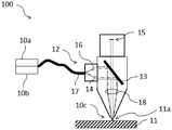
图1示意性地表示了根据本发明的实施方式的用于对工件进行激光加工的加工设备10的第一示例。Figure 1 schematically shows a first example of a
加工设备10具有用于产生加工激光束14的加工激光源10a。此外,提供了用于产生照明激光束16的照明激光源10b。另外,在加工设备10 中,存在用于加工激光束14和照明激光束16的出口开口10c。此外,提供了激光束引导装置。激光束引导装置被设计成使得加工激光束14和照明激光束16同轴地传导通过出口开口10c。在本示例中,激光束引导装置包括传输光纤17,加工激光源10a和照明激光源10b耦接至该传输光纤 17。加工激光源10a具有约6kW的功率,并且加工激光源10a在包括1070 nm的波长的光谱范围内生成加工激光束。照明激光源10b具有约300mW 的功率,并且生成具有在973nm至979nm的光谱范围内的中心波长、具有6nm的波长带的照明激光束16。The
为了加工由不锈钢制成的工件11,加工激光源10a和照明激光源10b 以上述功率和光谱范围投入操作。由加工激光源10a和照明激光源10b的生成的加工激光束14和照明激光束16穿过激光束引导装置17,并且最终同轴地通过出口开口10c,从而被同轴地朝向工件11引导。以这种方式,通过加工激光束14在加工区域11a中对工件进行加工,使得生成工件的自发光。另外,加工区域11a由照明激光束16照明,使得可以观察工件 11的激光加工。For machining the
激光加工中的自发光是热的,即工件的自发光与图2中所示的普朗克辐射光谱成比例。不锈钢的激光加工的处理温度在其熔化温度的范围内。不锈钢以及使用激光加工的其他金属——例如在平板切割系统上——通常具有低于3000K的熔化温度。这意味着包括不锈钢的这些金属在近红外区域中的最大热发射为760nm至2500nm。Self-luminescence in laser processing is thermal, that is, the self-luminescence of the workpiece is proportional to the Planck radiation spectrum shown in Figure 2. The processing temperature of laser machining of stainless steel is in the range of its melting temperature. Stainless steel and other metals machined using lasers - such as on flatbed cutting systems - typically have melting temperatures below 3000K. This means that these metals, including stainless steel, have a maximum thermal emission of 760 nm to 2500 nm in the near infrared region.
在上述范围内选择照明激光源10b的功率和照明激光束16的光谱范围,使得在激光加工期间,由照明激光束16产生的照明比加工区域11a 中工件的自发光更亮。The power of the
与不锈钢在近红外区域中的最大自发光的波长即大于1000nm的波长相比,可以在较小的波长下对其进行照明和观察。因此,与在最大不锈钢自发光的波长范围内的照明相比,针对照明激光束16的所选择的光谱范围需要较低的照明强度。以这种方式,与在所观察的光谱范围内的照明相比,工件11的自发光不太亮,因此可以以较低的工件的自发光来观察加工区域11a。Compared with the wavelength of maximum self-luminescence of stainless steel in the near-infrared region, that is, wavelengths greater than 1000 nm, it can be illuminated and observed at smaller wavelengths. Therefore, a lower illumination intensity is required for the selected spectral range of the
作为照明激光束16的光谱范围的替选或补充,根据要求或任务来调节照明功率,例如根据工件的表面结构、材料和/或形状如厚度,和/或根据要求的照明来调节照明功率。此外,可以根据加工设备的出口开口来调节照明激光源的功率,例如可选地根据加工头的辐照喷嘴来调节照明激光源的功率。此外,调节照明激光源的功率可以提高针对加工设备的操作者的安全性,特别是眼睛安全性。这特别是在维修开放式加工设备或开放式加工头时可以是有利的。例如,在这样的情况下或在类似的情况下,例如,具有至少50mW的功率的照明激光源可以减小至小于1mW功率,使得照明激光源对于眼睛基本上是安全的。Alternatively or in addition to the spectral range of the
如果使用具有至少50mW的功率的照明激光源,除了功率的调节之外,还可以采取与使用加工激光器类似的安全预防措施以保护操作者的眼睛。一种可能性是将照明激光器集成在加工激光器的安全电路中。安全电路允许照明激光源仅在确认激光释放和/或机器外壳关闭时开启。替选地,特别是在(开放式)激光头/机器内部的维修期间,要注意在没有眼睛安全预防措施例如安全性眼镜的情况下不要打开照明激光器。If an illumination laser source with a power of at least 50 mW is used, in addition to the adjustment of the power, similar safety precautions can be taken to protect the operator's eyes as with the processing laser. One possibility is to integrate the illumination laser in the safety circuit of the processing laser. A safety circuit allows the illuminating laser source to only be turned on when the laser release is confirmed and/or the machine enclosure is closed. Alternatively, especially during servicing inside the (open) laser head/machine, care is taken not to turn on the illuminating laser without eye safety precautions such as safety glasses.
在第一示例的修改中,照明激光源10a的功率为约50mW,并且所生成的照明激光束16具有在约486nm至490nm的范围内的中心波长。即使具有照明激光源的该功率和/或具有照明激光束的该光谱范围,不锈钢工件在所述光谱范围内的自发光与照明相比也不太亮,因此可以观察到加工区域11a具有减少或抑制的自发光。照明激光束的光谱范围被选择为4nm的波长带。该窄带有助于抑制或减少在加工过程期间的工件的自发光。此外,因为与照明的第一示例相比选择了较短的波长,所以需要较少的功率。In a modification of the first example, the power of the
第一示例的另一修改涉及传输光纤17。此处,传输光纤17被设计成具有内部光纤芯17a、包围内部光纤芯17a的外部光纤芯17b以及包围外部光纤芯17b的光纤包层17c。传输光纤17在图3a中以沿传输光纤17 的截面图示出,并且在图3b中以横向于传输光纤17的截面图示出。图 3c示出了与图3b的截面对应的传输光纤的折射率分布。加工激光源10a 和照明激光源10b耦接至传输光纤17,使得加工激光束14由内部光纤芯 17a引导,并且照明激光束16也由外部光纤芯17b部分地引导。这种配置使得工件的被照明的区域比工件的加工区域11a基本上大至少1.5倍。此外,照明激光束16可以附加地被引导通过光纤包层17c,其中同样地工件的被照明的区域大于加工区域。在所有这些情况下,借助于传输光纤17 同轴地引导加工激光束14和照明激光束16。Another modification of the first example involves the
应当注意的是,一些光纤被配置成没有外部芯,并且(内部)芯由包层直接围绕。在这种情况下,照明激光束也可以被引导通过光纤包层。在这样的示例中,光纤芯可以具有100μm的直径,并且围绕芯的光纤包层可以具有150μm或360μm的直径。It should be noted that some fibers are configured without an outer core, and the (inner) core is directly surrounded by the cladding. In this case, the illuminating laser beam can also be guided through the fiber cladding. In such an example, the fiber core may have a diameter of 100 μm, and the fiber cladding surrounding the core may have a diameter of 150 μm or 360 μm.
如在图3a至图3c的示例中,如果照明激光束16经由外部光纤芯17b 或者附加地经由传输光纤17的光纤包层17c传导,则照明激光束16比加工激光束14宽。加工激光束14仅由内部明显较小的光纤芯17a引导;参见图3a和图3b。由于工件11的加工区域11a在加工激光束16的延伸的区域内,因此加工区域11a小于照明区域。原则上可以在光纤设计期间选择外部芯17b的直径或光纤包层17c的直径。根据照明区域的期望延伸,可以选择相应大的光纤包层或外部芯直径。该措施确保加工区域11a周围的被照明的区域足够大,该措施与加工激光束14和照明激光束16的焦点位置无关。加工区域11a与照明区域的尺寸比特别地取决于外部芯17b的直径。光纤的设计是不同的,并且可以根据光纤17的制造商来选择;例如,内部光纤芯的直径可以为100μm,并且外部光纤芯的直径可以为150 μm或360μm(距光纤的中心)。The
在第一示例的进一步修改中,激光束引导装置包括传输光纤17或者不包括传输光纤17,并且包括选自以下组中的至少一个元件(图1中未示出):用于使加工激光束和/或照明激光束聚焦的至少一个光学单元,例如聚焦透镜;以及用于使照明激光束和/或加工激光束至少部分地偏转的至少一个单元,特别是二向色镜。在每种情况下,激光束引导装置使加工激光束和照明激光束同轴地被引导。In a further modification of the first example, the laser beam directing device includes or does not include a
如果在本示例及其修改中,加工激光束和照明激光束借助于传输光纤 17同轴地被引导,则不需要难以安装在加工设备上特别是难以安装在加工设备的加工头上的成本密集设计的照明激光源。另外,加工设备或加工头不会因为附加地安装在其上的照明激光源而变得更复杂或更重。If, in the present example and its modifications, the processing laser beam and the illumination laser beam are coaxially guided by means of the transmission
第一示例的另一修改包括视频摄像装置,作为用于检测从工件反射的照明激光束的检测器装置(图1中未示出),其中,检测器装置的光谱范围被选择或者是可调节的,使得检测器装置的光谱范围至少部分地与照明激光束特别是反射的照明激光束的光谱范围一致。在这种情况下,可以选择根据照明激光源的功率和照明激光束的光谱范围选择的元件,使得在所检测到的光谱范围中所检测到的自发光小于由工件反射和所检测到的照明激光束的功率。可以将检测器装置的所检测到的光谱范围选择为具有小于20nm、优选地小于10nm、更优选地小于5nm的宽度的波长带。此外,所检测到的光谱范围可以在照明激光束的光谱范围内,或者所检测到的光谱范围基本上检测到照明激光束的光谱范围或者所检测到的光谱范围基本上与照明激光束的光谱范围一致。例如,视频摄像装置可以用作同轴地记录观察区域的检测器装置。以这种方式,通过视频摄像装置监视加工区域。也可以使用一维的检测器阵列来代替二维的、空间分辨的检测单元,例如摄像装置,该一维的检测器阵列的定向被设置成横向于切割方向。使用切割方向,可以沿垂直于阵列的方向找到空间分辨率。Another modification of the first example includes a video camera device as a detector device (not shown in FIG. 1 ) for detecting the illuminating laser beam reflected from the workpiece, wherein the spectral range of the detector device is selected or adjustable so that the spectral range of the detector arrangement at least partially coincides with the spectral range of the illuminating laser beam, in particular the reflected illuminating laser beam. In this case, the elements selected according to the power of the illumination laser source and the spectral range of the illumination laser beam can be selected such that the self-luminescence detected in the detected spectral range is smaller than the reflection by the workpiece and the detected illumination The power of the laser beam. The detected spectral range of the detector device may be selected as a wavelength band having a width of less than 20 nm, preferably less than 10 nm, more preferably less than 5 nm. Furthermore, the detected spectral range may be within the spectral range of the illuminating laser beam, or the detected spectral range may be substantially the same as the spectral range of the illuminating laser beam, or substantially the same as the spectral range of the illuminating laser beam. The scope is the same. For example, a video camera device can be used as a detector device that records the observation area coaxially. In this way, the processing area is monitored by video cameras. Instead of a two-dimensional, spatially resolved detection unit, eg a camera, it is also possible to use a one-dimensional detector array oriented transversely to the cutting direction. Using the cutting direction, the spatial resolution can be found along the direction normal to the array.
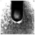
图5和图6示出了利用根据第一示例的以上修改的加工设备在不锈钢工件的激光切割过程中来自同轴视频摄像装置的记录。经加工的工件在激光切割过程期间热发射,即具有在大光谱范围内的宽带。如果仅在窄光谱带中检测,则工件的自发光的检测到的功率相应地低得多。激光是固有的窄带。激光的所有能量将仅存在于窄光谱带中。如果优选地仅在其中发射激光的光谱带中检测到窄带,则为了提供与自发光的亮度相比更亮的照明,需要显著较小的照明功率。在当前情况下,视觉印象特别重要。Figures 5 and 6 show recordings from a coaxial video camera during laser cutting of a stainless steel workpiece using the above modified processing apparatus according to the first example. The processed workpiece emits thermally during the laser cutting process, ie has a broad band over a large spectral range. If only a narrow spectral band is detected, the detected power of the self-luminescence of the workpiece is correspondingly much lower. Lasers are inherently narrowband. All the energy of the laser will only exist in a narrow spectral band. If a narrow band is preferably detected only in the spectral band in which the lasing is emitted, significantly less illumination power is required in order to provide brighter illumination compared to the brightness of self-luminescence. In the current situation, the visual impression is particularly important.
图5示出了在没有照明的情况下的激光切割过程的摄像装置记录。本质上,可以看到处理的自发光。在图6中,在切割过程中附加地开启照明激光器。对于来自图6的记录,与没有照明的情况相比,需要显著短的摄像装置曝光时间。自发光被强烈抑制(在切口间隙的中间人们仍然可以微弱地看到自发光);然而,切割间隙的环境清晰可见。Figure 5 shows a camera recording of the laser cutting process without illumination. Essentially, the self-illumination of the treatment can be seen. In Figure 6, the illumination laser is additionally switched on during the cutting process. For the recording from Figure 6, a significantly shorter camera exposure time is required compared to the case without illumination. Self-luminescence is strongly suppressed (one can still faintly see self-luminescence in the middle of the kerf gap); however, the environment of the kerf gap is clearly visible.
在进一步的修改中,激光束引导装置或者激光束引导装置的单个或多个元件至少部分地具有用于减少照明激光束的反射的外部涂层。涂层与所选择的照明和观察光谱相匹配。这使得反射的照明激光束16的最大可能部分被观察,并且发生尽可能少的光学单元的刺激性反射。特别地,以这种方式避免来自平面光学单元的反射是有利的。在该修改中,在照明激光束16的波长处,二向色镜具有例如约50%的反射与透射比。所有其他光学元件在照明波长处基本上是100%透射的。In a further modification, the laser beam guiding device or single or multiple elements of the laser beam guiding device at least partially have an outer coating for reducing reflections of the illuminating laser beam. The coating matches the chosen lighting and viewing spectrum. This allows the largest possible part of the reflected
图4示意性地示出了根据本发明的实施方式的用于对工件进行激光加工的加工设备100的第二示例。FIG. 4 schematically shows a second example of a
在图4的示例中,传输光纤17横向地耦接至加工设备100的加工头 12。此外,提供了二向色镜13,该二向色镜13对加工激光束14和照明激光束16进行反射,并且对于在照明的波长范围内由工件11反射的辐射为至少部分透明的。二向色镜13被定向在加工头12内,使得加工激光束 14和照明激光束16朝向出口开口10c偏转。另外,在二向色镜13与出口开口10c之间是光学单元,该光学单元在本示例中被设计为聚焦透镜18。此外,提供了以视频摄像装置15的形式的检测器装置。二向色镜13设置在聚焦透镜18与视频摄像装置15之间。这使得对于由工件反射的照明光束14可以至少部分地通过聚焦透镜18和二向色镜13入射在视频摄像装置15上。In the example of FIG. 4 , the
在操作期间,加工激光束16和照明激光束14经由传输光纤17被横向引导至加工头12中,在二向色镜13处朝向工件11偏转并且通过聚焦透镜18聚焦到工件11上。照明激光束14通过出口开口10c至少部分地反射回至加工头12中,照明激光束14透射通过聚焦透镜18和二向色镜 13并且入射在视频摄像装置15上。以这种方式,用照明激光束16来照明由加工激光14加工的工件11的加工区域11a,并且借助于至少部分地反射在视频摄像装置15上的照明激光束来观察该加工区域11a。During operation, the
在第二示例的变型中,从聚焦透镜18、加工激光源10a和照明激光源 10b中选择的至少一个元件被设计成或者可以被调节成:使得照明激光束 16的焦点和加工激光束14的焦点在轴向上彼此分开,特别是在光轴上彼此分开。这种设计促进了对加工区域11a周围足够大的区域的照明。特别地,照明区域可以较大,例如照明区域为加工区域11a的至少1.5倍大,优选地照明区域为加工区域11a的两倍大,加工区域11a也被称为处理相互作用区。In a variation of the second example, at least one element selected from focusing
根据特定的修改,加工激光源10a和照明激光源10b被设计成或者可以被调节成使得由加工激光源10a和照明激光源10b生成的激光束的光谱范围不同,并且聚焦透镜18被设计成为色散的。Depending on the particular modification, the
在第二示例的以上修改中,照明激光束16的焦点和加工激光束14的焦点不一致,而是照明激光束16的焦点和加工激光束14的焦点在光轴上轴向地彼此分开。这是通过以下事实来实现的:加工激光束14和照明激光束16的波长是发散的,并且光学单元——在本修改中为聚焦透镜18——被设计成为色散的,即光学单元具有取决于波长的折射率。光学单元具有取决于波长的折射率是基本上所有已知光学材料的情况。In the above modification of the second example, the focal points of the
利用已知的透镜焦距公式,在加工激光束14和照明激光束16的两个波长的焦距中存在差Δf=f2-f1。Using the known formula for the focal length of the lens, there is a difference Δf=f2 −f1 in the focal lengths of the two wavelengths of the

其中,两个波长的折射率由n1和n2表示,并且使用Δn=n2-n1。当使用成像光学单元此处为聚焦透镜18的大半径r1和r2并且Δn大时,Δf有利地大。由于在本示例中也具有1070nm的波长的加工激光束14,因此优选地是照明激光束16具有小于1070nm的波长、特别是具有蓝色光谱范围的波长。Here, the refractive indices of the two wavelengths are denoted by n1 and n2 , and Δn=n2 −n1 is used. Δf is advantageously large when using the large radii r1 and r2 of the imaging optical units, here focusing
根据第二示例的另一修改,借助于波束形成实现了照明中的进一步改善。在这种情况下,激光束引导装置包括用于对照明激光束进行选择性波束形成的单元,例如修改的聚焦透镜18,其被设计成使得工件11的被照明的区域大于工件11的加工区域,特别地工件11的被照明的区域为加工区域11a的至少1.5倍大,优选地为加工区域11a的两倍大。这种波束形成仅作用在照明激光束16上,而不作用在加工激光束14上。According to another modification of the second example, a further improvement in illumination is achieved by means of beamforming. In this case, the laser beam guiding device comprises a unit for selective beamforming of the illuminating laser beam, such as a modified focusing
所述选择性波束形成的示例可以是下述衍射光学元件,该衍射光学元件仅影响具有在照明激光波长的范围内的波长的辐射并且使加工激光束 14保持不变。作为衍射光学元件,也可以在(已经存在的)光学元件上使用衍射光栅。An example of such selective beamforming may be a diffractive optical element that only affects radiation having wavelengths in the range of illumination laser wavelengths and leaves the
另一示例可以是用于最佳照明的波束形成元件,该波束形成元件被实施和/或设计成使得仅在传输光纤17的外部芯上引导的照明激光束16受到影响,并且加工激光束14保持不变。Another example could be a beamforming element for optimal illumination that is implemented and/or designed such that only the
最后,应当注意,本发明的描述和示例性实施方式不应被理解为对在本发明的特定物理实现方面的限制。可以在根据本发明的主题中以不同的组合提供结合本发明的各个实施方式说明和示出的所有特征,以同时实现所有特征的有利效果。Finally, it should be noted that the description and exemplary embodiments of the present invention should not be construed as limiting in terms of the specific physical implementation of the present invention. All the features described and illustrated in connection with the various embodiments of the invention may be provided in different combinations in the subject matter according to the invention to achieve the advantageous effects of all features simultaneously.
本发明的保护范围由权利要求书给出,并且不受说明书中示出或附图中示出的特征的限制。The scope of the invention is given by the claims, and is not limited by the features shown in the description or shown in the drawings.
对于本领域技术人员而言特别明显的是,本发明不仅可以用于激光加工系统,而且可以用于包括激光器的其他装置。此外,用于对工件进行激光加工的加工设备的部件可以被制造成分布在若干个物理产品上。It will be particularly apparent to those skilled in the art that the present invention can be used not only in laser processing systems, but also in other devices including lasers. Furthermore, the components of the processing equipment used to laser process the workpiece can be manufactured to be distributed over several physical products.
附图标记列表List of reference signs
10 加工设备10 Processing equipment
10a 加工激光源10a Processing laser source
10b 照明激光源10b Illumination laser source
10c 出口开口10c outlet opening
11 工件11 workpieces
11a 加工区域11a Processing area
12 加工头12 Processing heads
13 二向色镜13 Dichroic mirror
14 加工激光束14 Processing laser beam
15 检测器装置,例如视频摄像装置15 Detector devices, such as video cameras
16 照明激光束16 Illumination laser beam
17 激光束引导装置,例如传输光纤17 Laser beam guiding devices, such as transmission fibers
17a 内部光纤芯17a Internal Fiber Core
17b 外部光纤芯17b External fiber core
17c 光纤包层17c Fiber Cladding
18 光学单元,例如聚焦透镜18 Optical units such as focusing lenses
100 加工设备100 Processing Equipment
Claims (48)
Translated fromChineseApplications Claiming Priority (3)
| Application Number | Priority Date | Filing Date | Title |
|---|---|---|---|
| DE1020181268467 | 2018-10-26 | ||
| DE102018126846.7ADE102018126846A1 (en) | 2018-10-26 | 2018-10-26 | Machining device for laser machining a workpiece and method for laser machining a workpiece |
| PCT/EP2019/079185WO2020084114A1 (en) | 2018-10-26 | 2019-10-25 | Machining apparatus for laser machining a workpiece and method for laser machining a workpiece |
Publications (2)
| Publication Number | Publication Date |
|---|---|
| CN113015594A CN113015594A (en) | 2021-06-22 |
| CN113015594Btrue CN113015594B (en) | 2022-09-23 |
Family
ID=68392984
Family Applications (1)
| Application Number | Title | Priority Date | Filing Date |
|---|---|---|---|
| CN201980070632.6AActiveCN113015594B (en) | 2018-10-26 | 2019-10-25 | Machining device for laser machining a workpiece and method for laser machining a workpiece |
Country Status (6)
| Country | Link |
|---|---|
| US (1) | US12194563B2 (en) |
| EP (1) | EP3870385B1 (en) |
| JP (1) | JP6992214B2 (en) |
| CN (1) | CN113015594B (en) |
| DE (1) | DE102018126846A1 (en) |
| WO (1) | WO2020084114A1 (en) |
Families Citing this family (3)
| Publication number | Priority date | Publication date | Assignee | Title |
|---|---|---|---|---|
| EP4292753A1 (en)* | 2022-06-16 | 2023-12-20 | Bystronic Laser AG | Determining the degree of fouling of a transmissive element |
| DE102022128180A1 (en)* | 2022-10-25 | 2024-04-25 | TRUMPF Werkzeugmaschinen SE + Co. KG | Media supply during laser welding |
| EP4628243A1 (en) | 2024-04-04 | 2025-10-08 | Bystronic Laser AG | Flatbed laser cutting machine, system and method |
Citations (8)
| Publication number | Priority date | Publication date | Assignee | Title |
|---|---|---|---|---|
| CN101226892A (en)* | 2007-01-15 | 2008-07-23 | 株式会社迪思科 | Measuring device for workpiece held on chuck table and laser processing machine |
| CN102059451A (en)* | 2010-11-08 | 2011-05-18 | 北京理工大学 | Nano-femtosecond dual-laser composite machining system |
| CN102905841A (en)* | 2010-05-11 | 2013-01-30 | 普雷茨特两合公司 | Laser cutting head and method for cutting a workpiece by means of a laser cutting head |
| DE102012001609B3 (en)* | 2012-01-26 | 2013-02-21 | Precitec Kg | Laser processing head |
| CN103212842A (en)* | 2012-01-19 | 2013-07-24 | 昆山思拓机器有限公司 | Laser cutting equipment for stents |
| CN103597674A (en)* | 2011-05-04 | 2014-02-19 | 通快激光两合公司 | Laser processing system with processing laser beam adjustable in brightness |
| CN105531071A (en)* | 2013-09-13 | 2016-04-27 | 通快机床两合公司 | Devices and methods for monitoring, more particularly controlling, a cutting process |
| CN106102981A (en)* | 2014-03-12 | 2016-11-09 | 三菱电机株式会社 | Laser machining head device with camera surveillance device |
Family Cites Families (8)
| Publication number | Priority date | Publication date | Assignee | Title |
|---|---|---|---|---|
| JPH11344417A (en) | 1998-06-03 | 1999-12-14 | Amada Eng Center Co Ltd | Detecting method for fracture and incidence deviation of optical fiber and laser machining apparatus |
| JP3038196B1 (en) | 1998-10-30 | 2000-05-08 | ファナック株式会社 | Laser light concentrator |
| JP4613274B2 (en)* | 2001-06-21 | 2011-01-12 | 独立行政法人 日本原子力研究開発機構 | Laser processing system using composite optical fiber |
| US8983259B2 (en)* | 2012-05-04 | 2015-03-17 | Raytheon Company | Multi-function beam delivery fibers and related system and method |
| DE102014214427B4 (en)* | 2014-07-23 | 2021-11-18 | Technische Universität Dresden | Method and device for removing a coating from a surface of a base material |
| JP6738088B2 (en)* | 2016-09-20 | 2020-08-12 | 株式会社Okファイバーテクノロジー | Laser irradiation device |
| JP6367886B2 (en) | 2016-10-14 | 2018-08-01 | ファナック株式会社 | Laser processing equipment |
| JP6306659B1 (en) | 2016-10-19 | 2018-04-04 | ファナック株式会社 | Beam distributor |
- 2018
- 2018-10-26DEDE102018126846.7Apatent/DE102018126846A1/ennot_activeWithdrawn
- 2019
- 2019-10-25USUS17/288,553patent/US12194563B2/enactiveActive
- 2019-10-25CNCN201980070632.6Apatent/CN113015594B/enactiveActive
- 2019-10-25EPEP19795526.3Apatent/EP3870385B1/enactiveActive
- 2019-10-25JPJP2021522939Apatent/JP6992214B2/enactiveActive
- 2019-10-25WOPCT/EP2019/079185patent/WO2020084114A1/ennot_activeCeased
Patent Citations (9)
| Publication number | Priority date | Publication date | Assignee | Title |
|---|---|---|---|---|
| CN101226892A (en)* | 2007-01-15 | 2008-07-23 | 株式会社迪思科 | Measuring device for workpiece held on chuck table and laser processing machine |
| CN102905841A (en)* | 2010-05-11 | 2013-01-30 | 普雷茨特两合公司 | Laser cutting head and method for cutting a workpiece by means of a laser cutting head |
| CN102059451A (en)* | 2010-11-08 | 2011-05-18 | 北京理工大学 | Nano-femtosecond dual-laser composite machining system |
| CN103597674A (en)* | 2011-05-04 | 2014-02-19 | 通快激光两合公司 | Laser processing system with processing laser beam adjustable in brightness |
| CN103212842A (en)* | 2012-01-19 | 2013-07-24 | 昆山思拓机器有限公司 | Laser cutting equipment for stents |
| DE102012001609B3 (en)* | 2012-01-26 | 2013-02-21 | Precitec Kg | Laser processing head |
| WO2013110467A1 (en)* | 2012-01-26 | 2013-08-01 | Precitec Gmbh & Co. Kg | Laser machining head with focus control |
| CN105531071A (en)* | 2013-09-13 | 2016-04-27 | 通快机床两合公司 | Devices and methods for monitoring, more particularly controlling, a cutting process |
| CN106102981A (en)* | 2014-03-12 | 2016-11-09 | 三菱电机株式会社 | Laser machining head device with camera surveillance device |
Also Published As
| Publication number | Publication date |
|---|---|
| JP2021536370A (en) | 2021-12-27 |
| US12194563B2 (en) | 2025-01-14 |
| US20210354235A1 (en) | 2021-11-18 |
| WO2020084114A1 (en) | 2020-04-30 |
| CN113015594A (en) | 2021-06-22 |
| EP3870385B1 (en) | 2022-04-13 |
| EP3870385A1 (en) | 2021-09-01 |
| DE102018126846A1 (en) | 2020-04-30 |
| JP6992214B2 (en) | 2022-01-13 |
Similar Documents
| Publication | Publication Date | Title |
|---|---|---|
| CN113015594B (en) | Machining device for laser machining a workpiece and method for laser machining a workpiece | |
| DE102012001609B3 (en) | Laser processing head | |
| US11491583B2 (en) | Methods and apparatuses for controlling cutting processes | |
| CN102905841B (en) | Laser cutting head and for the method by means of laser cutting head cut workpiece | |
| EP2176631B1 (en) | Monitoring the temperature of an optical element | |
| DE19949198B4 (en) | Device having at least one light source comprising a plurality of individual light sources | |
| JP6114431B1 (en) | Laser processing machine | |
| JPWO2015137179A1 (en) | Laser processing head device with camera monitor | |
| KR20100090184A (en) | Laser processing head with integrated sensor device for monitoring focal position | |
| JP5965454B2 (en) | Direct diode laser processing apparatus and sheet metal processing method using the same | |
| JP6873062B2 (en) | Laser processing head and laser processing equipment equipped with a laser processing head | |
| CN111479648B (en) | Apparatus, method and use for monitoring beam processing of workpieces | |
| US5850068A (en) | Focus control of lasers in material processing operations | |
| US12076811B2 (en) | Device for laser machining workpieces that are difficult to access | |
| JP6637916B2 (en) | Laser processing machine | |
| WO2021182122A1 (en) | Laser welding monitoring device and laser welding monitoring method | |
| US5562842A (en) | Material treatment apparatus combining a laser diode and an illumination light with a video imaging system | |
| US20240091883A1 (en) | Process Monitor for Laser Processing Head | |
| JP2017189801A (en) | Laser processing machine, and laser processing method | |
| JP5667344B2 (en) | Laser emission unit | |
| WO2020184540A1 (en) | Laser processing device | |
| JP7157450B2 (en) | Laser processing equipment | |
| JP7236371B2 (en) | Beam shaper, processing device, and beam shaping method |
Legal Events
| Date | Code | Title | Description |
|---|---|---|---|
| PB01 | Publication | ||
| PB01 | Publication | ||
| SE01 | Entry into force of request for substantive examination | ||
| SE01 | Entry into force of request for substantive examination | ||
| GR01 | Patent grant | ||
| GR01 | Patent grant |