CN113015547B - Device counter - Google Patents
Device counterDownload PDFInfo
- Publication number
- CN113015547B CN113015547BCN201880097160.9ACN201880097160ACN113015547BCN 113015547 BCN113015547 BCN 113015547BCN 201880097160 ACN201880097160 ACN 201880097160ACN 113015547 BCN113015547 BCN 113015547B
- Authority
- CN
- China
- Prior art keywords
- chassis
- inhaler
- blade
- cantilevered
- shelf
- Prior art date
- Legal status (The legal status is an assumption and is not a legal conclusion. Google has not performed a legal analysis and makes no representation as to the accuracy of the status listed.)
- Active
Links
Images


Classifications
- A—HUMAN NECESSITIES
- A61—MEDICAL OR VETERINARY SCIENCE; HYGIENE
- A61M—DEVICES FOR INTRODUCING MEDIA INTO, OR ONTO, THE BODY; DEVICES FOR TRANSDUCING BODY MEDIA OR FOR TAKING MEDIA FROM THE BODY; DEVICES FOR PRODUCING OR ENDING SLEEP OR STUPOR
- A61M15/00—Inhalators
- A61M15/0001—Details of inhalators; Constructional features thereof
- A61M15/0021—Mouthpieces therefor
- A61M15/0025—Mouthpieces therefor with caps
- A61M15/0026—Hinged caps
- A—HUMAN NECESSITIES
- A61—MEDICAL OR VETERINARY SCIENCE; HYGIENE
- A61M—DEVICES FOR INTRODUCING MEDIA INTO, OR ONTO, THE BODY; DEVICES FOR TRANSDUCING BODY MEDIA OR FOR TAKING MEDIA FROM THE BODY; DEVICES FOR PRODUCING OR ENDING SLEEP OR STUPOR
- A61M15/00—Inhalators
- A61M15/0001—Details of inhalators; Constructional features thereof
- A61M15/0021—Mouthpieces therefor
- A—HUMAN NECESSITIES
- A61—MEDICAL OR VETERINARY SCIENCE; HYGIENE
- A61M—DEVICES FOR INTRODUCING MEDIA INTO, OR ONTO, THE BODY; DEVICES FOR TRANSDUCING BODY MEDIA OR FOR TAKING MEDIA FROM THE BODY; DEVICES FOR PRODUCING OR ENDING SLEEP OR STUPOR
- A61M15/00—Inhalators
- A61M15/0028—Inhalators using prepacked dosages, one for each application, e.g. capsules to be perforated or broken-up
- A61M15/003—Inhalators using prepacked dosages, one for each application, e.g. capsules to be perforated or broken-up using capsules, e.g. to be perforated or broken-up
- A61M15/0031—Inhalators using prepacked dosages, one for each application, e.g. capsules to be perforated or broken-up using capsules, e.g. to be perforated or broken-up by bursting or breaking the package, i.e. without cutting or piercing
- A—HUMAN NECESSITIES
- A61—MEDICAL OR VETERINARY SCIENCE; HYGIENE
- A61M—DEVICES FOR INTRODUCING MEDIA INTO, OR ONTO, THE BODY; DEVICES FOR TRANSDUCING BODY MEDIA OR FOR TAKING MEDIA FROM THE BODY; DEVICES FOR PRODUCING OR ENDING SLEEP OR STUPOR
- A61M15/00—Inhalators
- A61M15/0028—Inhalators using prepacked dosages, one for each application, e.g. capsules to be perforated or broken-up
- A61M15/0045—Inhalators using prepacked dosages, one for each application, e.g. capsules to be perforated or broken-up using multiple prepacked dosages on a same carrier, e.g. blisters
- A61M15/0046—Inhalators using prepacked dosages, one for each application, e.g. capsules to be perforated or broken-up using multiple prepacked dosages on a same carrier, e.g. blisters characterized by the type of carrier
- A61M15/0048—Inhalators using prepacked dosages, one for each application, e.g. capsules to be perforated or broken-up using multiple prepacked dosages on a same carrier, e.g. blisters characterized by the type of carrier the dosages being arranged in a plane, e.g. on diskettes
- A—HUMAN NECESSITIES
- A61—MEDICAL OR VETERINARY SCIENCE; HYGIENE
- A61M—DEVICES FOR INTRODUCING MEDIA INTO, OR ONTO, THE BODY; DEVICES FOR TRANSDUCING BODY MEDIA OR FOR TAKING MEDIA FROM THE BODY; DEVICES FOR PRODUCING OR ENDING SLEEP OR STUPOR
- A61M15/00—Inhalators
- A61M15/0028—Inhalators using prepacked dosages, one for each application, e.g. capsules to be perforated or broken-up
- A61M15/0061—Inhalators using prepacked dosages, one for each application, e.g. capsules to be perforated or broken-up using pre-packed dosages having an insert inside
- A—HUMAN NECESSITIES
- A61—MEDICAL OR VETERINARY SCIENCE; HYGIENE
- A61M—DEVICES FOR INTRODUCING MEDIA INTO, OR ONTO, THE BODY; DEVICES FOR TRANSDUCING BODY MEDIA OR FOR TAKING MEDIA FROM THE BODY; DEVICES FOR PRODUCING OR ENDING SLEEP OR STUPOR
- A61M15/00—Inhalators
- A61M15/0065—Inhalators with dosage or measuring devices
- A61M15/0068—Indicating or counting the number of dispensed doses or of remaining doses
- A61M15/007—Mechanical counters
- G—PHYSICS
- G06—COMPUTING OR CALCULATING; COUNTING
- G06M—COUNTING MECHANISMS; COUNTING OF OBJECTS NOT OTHERWISE PROVIDED FOR
- G06M1/00—Design features of general application
- G06M1/08—Design features of general application for actuating the drive
- G06M1/083—Design features of general application for actuating the drive by mechanical means
- A—HUMAN NECESSITIES
- A61—MEDICAL OR VETERINARY SCIENCE; HYGIENE
- A61M—DEVICES FOR INTRODUCING MEDIA INTO, OR ONTO, THE BODY; DEVICES FOR TRANSDUCING BODY MEDIA OR FOR TAKING MEDIA FROM THE BODY; DEVICES FOR PRODUCING OR ENDING SLEEP OR STUPOR
- A61M2202/00—Special media to be introduced, removed or treated
- A61M2202/06—Solids
- A61M2202/064—Powder
- A—HUMAN NECESSITIES
- A61—MEDICAL OR VETERINARY SCIENCE; HYGIENE
- A61M—DEVICES FOR INTRODUCING MEDIA INTO, OR ONTO, THE BODY; DEVICES FOR TRANSDUCING BODY MEDIA OR FOR TAKING MEDIA FROM THE BODY; DEVICES FOR PRODUCING OR ENDING SLEEP OR STUPOR
- A61M2205/00—General characteristics of the apparatus
- A61M2205/58—Means for facilitating use, e.g. by people with impaired vision
- A61M2205/582—Means for facilitating use, e.g. by people with impaired vision by tactile feedback
- A—HUMAN NECESSITIES
- A61—MEDICAL OR VETERINARY SCIENCE; HYGIENE
- A61M—DEVICES FOR INTRODUCING MEDIA INTO, OR ONTO, THE BODY; DEVICES FOR TRANSDUCING BODY MEDIA OR FOR TAKING MEDIA FROM THE BODY; DEVICES FOR PRODUCING OR ENDING SLEEP OR STUPOR
- A61M2206/00—Characteristics of a physical parameter; associated device therefor
- A61M2206/10—Flow characteristics
- A61M2206/20—Flow characteristics having means for promoting or enhancing the flow, actively or passively
Landscapes
- Health & Medical Sciences (AREA)
- Engineering & Computer Science (AREA)
- Life Sciences & Earth Sciences (AREA)
- Heart & Thoracic Surgery (AREA)
- Animal Behavior & Ethology (AREA)
- Pulmonology (AREA)
- Anesthesiology (AREA)
- Biomedical Technology (AREA)
- Veterinary Medicine (AREA)
- Hematology (AREA)
- Bioinformatics & Cheminformatics (AREA)
- General Health & Medical Sciences (AREA)
- Public Health (AREA)
- Biophysics (AREA)
- Physics & Mathematics (AREA)
- General Physics & Mathematics (AREA)
- Theoretical Computer Science (AREA)
- Medicinal Preparation (AREA)
- Medical Preparation Storing Or Oral Administration Devices (AREA)
Abstract
Translated fromChinese
Description
Translated fromChinese背景技术Background technique
用于药物输送的吸入技术的发展为治疗各种肺内和肺外疾病做出了巨大贡献。这受到肺部独特的几何形状(例如大表面积、薄薄的肺泡上皮内衬、高血管化作用和避免首过代谢)支持。已经开发和研究了许多吸入输送系统来治疗肺部疾病,例如哮喘、慢性阻塞性肺疾病(COPD)和其他肺部感染。其中,广泛审查了三种方法即雾化器、加压定量吸入器(pMDI)和干粉吸入器(DPI),以治疗多种肺部疾病和病理状况。雾化器的使用需要大体积的压缩机或压缩空气源,而pMDI具有局限性,例如沉降、晶体生长和选择合适的推进剂,并且它们会高速释放剂量,从而在口咽中形成沉积,最常见的是它们被吞咽并增加全身吸收的风险。引入DPI是为了解决与雾化器和pMDI相关的某些弱点。The development of inhalation technology for drug delivery has greatly contributed to the treatment of various intrapulmonary and extrapulmonary diseases. This is supported by the unique geometry of the lung, such as large surface area, thin alveolar epithelial lining, high vascularization, and avoidance of first-pass metabolism. A number of inhalation delivery systems have been developed and investigated to treat pulmonary diseases such as asthma, chronic obstructive pulmonary disease (COPD) and other lung infections. Among these, three methods, namely nebulizers, pressurized metered dose inhalers (pMDIs) and dry powder inhalers (DPIs), were extensively reviewed for the treatment of various pulmonary diseases and pathological conditions. The use of nebulizers requires a large volume compressor or source of compressed air, while pMDIs have limitations such as settling, crystal growth, and selection of appropriate propellants, and they release doses at high rates, creating deposits in the oropharynx, most It is common that they are swallowed and increase the risk of systemic absorption. DPI was introduced to address certain weaknesses associated with nebulizers and pMDIs.
已知有各种各样的装置以粉末形式分配剂量药物用于吸入。已知的装置包含粉末状药物储存器,根据需要从中计量出各个剂量。还已知的装置包括具有容纳相应剂量粉末的多个袋的托架。这些托架通常为泡罩包装的形式。所有这些装置都面临着提供可靠、可重复和准确的吸入量粉末的问题。Various devices are known for dispensing doses of medicament in powder form for inhalation. Known devices contain powdered drug reservoirs, from which individual doses are metered out as required. Devices are also known comprising a tray with a plurality of bags containing respective doses of powder. These trays are usually in the form of blister packs. All of these devices face the problem of providing a reliable, repeatable and accurate inhaled amount of powder.
在确保将所有分配剂量粉末夹带到气流中进行吸入方面存在问题。在根据需要提供粉末到吸入气流中的可重复和一致的释放方面还有其他问题,药物输送过量或不足的问题。例如,当通过不完全致动杆或不遵循其他使用说明而误用吸入装置时,计数器可能在给使用者提供剂量之前减小,并且使用者可能缺少所需的药物。这些错误可以重复多次执行。There is a problem with ensuring that all of the dispensed dose powder is entrained into the air stream for inhalation. There are additional problems in providing repeatable and consistent release of the powder into the inhalation stream as needed, the problem of over or under delivery of the drug. For example, when the inhaler is misused by not fully actuating the lever or by not following other instructions for use, the counter may decrement before a dose is provided to the user, and the user may be short of required medication. These errors can be repeated multiple times.
因此,提供一种具有设计特征的吸入装置将是有益的,该设计特征将使计数器错误计数和/或分度错误的发生率最小化。Accordingly, it would be beneficial to provide an inhalation device with design features that minimize the incidence of counter miscounts and/or indexing errors.
发明内容Contents of the invention
本申请提供了一种用于吸入器的灌注构件。灌注构件包括构造成与吸入器的底盘接合的悬臂叶片。悬臂叶片具有近端部分、主体和远端部分,主体设置在悬臂叶片的近端部分与远端部分之间。悬臂叶片具有挠性部分,该挠性部分与悬臂叶片的近端部分一起延伸,以允许悬臂叶片相对于灌注构件移动。悬臂叶片的挠性部分是铰链挠曲,其允许悬臂叶片相对于吸入装置的底盘沿向上和向下方向移动。The present application provides an irrigation member for an inhaler. The irrigation member includes a cantilevered blade configured to engage the chassis of the inhaler. The cantilever blade has a proximal portion, a body and a distal portion, the body being disposed between the proximal portion and the distal portion of the cantilever blade. The cantilevered blade has a flexible portion extending with the proximal portion of the cantilevered blade to allow movement of the cantilevered blade relative to the irrigation member. The flexible part of the cantilever vane is a hinge flexure that allows the cantilever vane to move in an upward and downward direction relative to the chassis of the suction device.
悬臂叶片适于在致动吸入器时在底盘的架子上方越过,而在分度吸入器时在底盘的架子下方越过。悬臂叶片的主体包括从悬臂叶片的近端部分延伸至远端部分的纵向轴线,并且挠性部分沿横向轴线横向于纵向轴线延伸。悬臂叶片还包括沿着悬臂叶片的纵向轴线延伸的第一表面和第二表面,第一表面与第二表面相对,从而在灌注构件与悬臂叶片的第一表面之间形成第一间隙,并且在第二表面与灌注构件之间形成第二间隙。悬臂叶片的远端部分包括成角度的尖端,在某些方面,其可以被倒角。在一些方面,悬臂叶片具有楔形形状或矩形形状。The cantilever vane is adapted to pass over the shelf of the chassis when the inhaler is actuated and to pass under the shelf of the chassis when the inhaler is indexed. The main body of the cantilever blade includes a longitudinal axis extending from the proximal portion to the distal portion of the cantilever blade, and the flexible portion extends along the transverse axis transverse to the longitudinal axis. The cantilever blade also includes a first surface and a second surface extending along the longitudinal axis of the cantilever blade, the first surface opposing the second surface, thereby forming a first gap between the irrigation member and the first surface of the cantilever blade, and at A second gap is formed between the second surface and the irrigation member. The distal portion of the cantilever blade includes an angled tip, which in some aspects may be chamfered. In some aspects, the cantilever blade has a wedge shape or a rectangular shape.
该申请还提供了一种用于吸入剂量粉末的吸入器。吸入器包括用于吸入剂量粉末的衔嘴;以及灌注构件,其包括构造成与吸入器的底盘接合的悬臂叶片。灌注构件的悬臂叶片具有近端部分、主体和远端部分,主体设置在悬臂叶片的近端部分与远端部分之间,并且悬臂叶片具有挠性部分,该挠性部分与悬臂叶片的近端部分一起延伸,以允许悬臂叶片相对于流体联接至衔嘴的灌注构件移动。The application also provides an inhaler for inhaling dosed powders. The inhaler includes a mouthpiece for inhaling a dose of powder; and an infusion member including a cantilevered blade configured to engage a chassis of the inhaler. The cantilevered blade of the perfusion member has a proximal portion, a main body and a distal portion, the main body is disposed between the proximal portion and the distal portion of the cantilevered blade, and the cantilevered blade has a flexible portion that engages with the proximal end of the cantilevered blade The portions extend together to allow the cantilevered blade to move relative to the irrigation member fluidly coupled to the mouthpiece.
还提供了一种用于吸入器的底盘。底盘包括:板,其具有邻近第一孔设置的引导构件;枢转轴,其构造成用于支撑灌注构件;周边外壳,其构造成用于可旋转地支撑具有药物的袋;夹子,其具有第二孔,用于接收在偏离中心轴线的轴线上可旋转地安装在底盘上的轮;以及架子,其邻近第二孔设置,架子限定第三孔,第三孔构造为用于接收吸入器的灌注构件的悬臂叶片。底盘还包括在底盘上的多个径向定位的肋和在底盘上的多个周向定位的支柱,支柱构造成用于稳定底盘和吸入器的灌注构件。在一些实施例中,第三孔在一端处被壁包围,而在另一端处被边缘支撑件包围。在其他实施例中,底盘还包括较低的台阶和较高的台阶,台阶周向定位在底盘上以允许模制。A chassis for the inhaler is also provided. The chassis includes: a plate having a guide member disposed adjacent to the first hole; a pivot shaft configured to support the priming member; a peripheral housing configured to rotatably support a bag with the drug; a clip having a second aperture. Two holes for receiving wheels rotatably mounted on the chassis on an axis offset from the central axis; and a shelf adjacent to the second hole, the shelf defining a third hole configured for receiving the inhaler Cantilever blades for perfusion components. The chassis also includes a plurality of radially positioned ribs on the chassis and a plurality of circumferentially positioned struts on the chassis configured to stabilize the chassis and the infusion member of the inhaler. In some embodiments, the third aperture is surrounded at one end by a wall and at the other end by an edge support. In other embodiments, the chassis also includes a lower step and an upper step, the steps being positioned circumferentially on the chassis to allow molding.
在各个实施例中,提供了一种吸入器,该吸入器包括:具有支座构件和中空枢轴的底盘;分配机构以及分度机构,底盘支撑分配机构和分度机构;分配机构包括灌注构件,该灌注构件包括灌注杆、安装在灌注构件上的第一刺棒和第二刺棒、作为分度机构的一部分可移动的中心凸轮、适于由底盘的中空枢轴可旋转地支撑的枢转开口、驱动构件和肋,该肋将中心凸轮连接到驱动构件;并且分度机构包括槽轮,其在偏离中心轴线的轴线上可旋转地安装在底盘上。在一些应用中,驱动构件还包括通过铰链挠曲固定至灌注构件的刚性悬臂叶片,悬臂叶片适于在致动吸入装置时在底盘的架子上方越过,而在分度吸入装置时在架子下方越过。在其他应用中,第一刺棒和第二刺棒可在缩回位置和伸出位置之间朝向和远离吸入装置的被支撑的第一和第二托架的第二侧表面移动。In various embodiments, there is provided an inhaler comprising: a chassis having a standoff member and a hollow pivot; a dispensing mechanism and an indexing mechanism, the chassis supporting the dispensing mechanism and the indexing mechanism; the dispensing mechanism comprising a priming member , the perfusion member comprises a perfusion rod, a first prod and a second prong mounted on the perfusion member, a central cam movable as part of an indexing mechanism, a pivot adapted to be rotatably supported by a hollow pivot of the chassis and a rib connecting the central cam to the drive member; and an indexing mechanism comprising a sheave rotatably mounted on the chassis on an axis offset from the central axis. In some applications, the drive member also includes a rigid cantilevered blade fixed to the irrigation member by hinge flexure, the cantilevered blade being adapted to pass over a shelf of the chassis when the suction device is actuated, and to pass under the shelf when indexing the suction device . In other applications, the first prod and the second prod are movable toward and away from the second side surface of the supported first and second brackets of the inhalation device between a retracted position and an extended position.
在各个实施例中,灌注构件还包括:细长凸轮构件,其从中心凸轮朝向与灌注构件的驱动构件的前部相对设置的凹部延伸;侧向凸轮表面和至少细长开口,灌注构件的至少细长开口和底盘的架子布置成旋转地保持刺棒,以允许刺棒通过中心凸轮表面和侧向凸轮表面朝向和远离被支撑的第一和第二托架移动。槽轮包括钉轮和与钉轮同轴的两个齿轮,钉轮适于与灌注构件配合。在一些方面,分度机构布置成用于使第一支撑件和第二支撑件相对于第一和第二刺棒移动,以便选择性地将托架的袋与相应的刺棒对准。In various embodiments, the irrigation member further comprises: an elongated cam member extending from a central cam towards a recess disposed opposite the front of the drive member of the irrigation member; a lateral cam surface and at least an elongated opening through which at least The elongated opening and the shelf of the chassis are arranged to rotatably retain the goad to allow movement of the goad towards and away from the supported first and second brackets via the central cam surface and the lateral cam surfaces. The sheave includes a spiked wheel and two gears coaxial with the spiked wheel, the spiked wheel is adapted to cooperate with the pouring member. In some aspects, the indexing mechanism is arranged to move the first support and the second support relative to the first and second prods to selectively align the pockets of the carrier with the corresponding prods.
在各个方面,当灌注杆开始致动行程时,如果未将灌注杆推到行程的末端时,则灌注杆将返回架子的顶部上,而无需对剂量托架或计数器进行分度,并且计数器暂时显示在所服用的多个剂量之后的一个分度。在其他方面,当灌注杆在致动行程的末端从底盘的架子的端部下落时,灌注杆在底盘的架子下方越过以接合槽轮,从而推进剂量托架并减少计数器,并且计数器正确地表示所服用的剂量数量。In all respects, when the priming rod begins its actuation stroke, if the priming rod is not pushed to the end of the stroke, the priming rod will return to the top of the shelf without indexing the dose carriage or counter and the counter temporarily Displays a graduation after the number of doses taken. In other respects, when the priming rod is dropped from the end of the chassis' shelf at the end of the actuation stroke, the priming rod passes under the chassis' shelf to engage the sheave, thereby advancing the dose carriage and decrementing the counter, and the counter correctly indicates The number of doses taken.
在一些实施例中,提供了一种治疗呼吸系统疾病的方法。该治疗方法包括:从吸入器吸入用于治疗呼吸系统疾病的粉末,吸入器包括用于吸入剂量粉末的衔嘴;以及灌注构件,其包括悬臂叶片,该悬臂叶片构造成与吸入器的底盘接合,该灌注构件具有近端部分、锥形主体和远端部分,该锥形主体设置在悬臂叶片的近端部分和远端部分之间,并且悬臂叶片具有挠性部分,该挠性部分与悬臂叶片的近端部分一起延伸,以允许悬臂叶片相对于流体联接至衔嘴的灌注构件移动。In some embodiments, a method of treating a respiratory disease is provided. The method of treatment comprises: inhaling a powder for treating a respiratory disease from an inhaler comprising a mouthpiece for inhaling a dose of powder; and an infusion member comprising a cantilevered blade configured to engage a chassis of the inhaler , the perfusion member has a proximal portion, a tapered body and a distal portion, the tapered body is disposed between the proximal portion and the distal portion of the cantilever blade, and the cantilever blade has a flexible portion that is connected to the cantilever Proximal portions of the blades extend together to allow movement of the cantilevered blade relative to an irrigation member fluidly coupled to the mouthpiece.
在其他方面,提供了一种治疗呼吸系统疾病的方法。该治疗方法包括:从吸入器吸入用于治疗呼吸道疾病的粉末,该吸入器包括具有支座构件和中空枢轴的底盘;分配机构和分度机构,底盘支撑分配机构和分度机构,分配机构包括灌注构件,该灌注构件包括灌注杆、安装在灌注构件上的第一刺棒和第二刺棒、作为分度机构的一部分可移动的中心凸轮、适于由底盘的中空枢轴可旋转地支撑的枢转开口、驱动构件和肋,该肋将中心凸轮连接到驱动构件;并且分度机构包括槽轮,其在偏离中心轴线的轴线上可旋转地安装在底盘上。在该方法中使用的驱动构件还包括通过铰链挠曲固定至灌注构件的刚性悬臂叶片,悬臂叶片适于在致动吸入装置时在底盘的架子上方越过,而在分度吸入装置时在架子下方越过。In other aspects, a method of treating a respiratory disease is provided. The method of treatment comprises: inhaling powder for treating respiratory diseases from an inhaler comprising a chassis having a support member and a hollow pivot; a dispensing mechanism and an indexing mechanism, the chassis supporting the dispensing mechanism and the indexing mechanism, the dispensing mechanism Including a pouring member comprising a pouring rod, first and second prods mounted on the pouring member, a central cam movable as part of an indexing mechanism, adapted to be rotatably moved by a hollow pivot of the chassis a supported pivot opening, a drive member and a rib connecting the central cam to the drive member; and an indexing mechanism comprising a sheave rotatably mounted on the chassis on an axis offset from the central axis. The drive member used in the method also includes a rigid cantilevered blade secured to the perfusion member by hinge flexure, the cantilevered blade being adapted to pass over the shelf of the chassis when the suction device is actuated, and below the shelf when indexing the suction device over.
在其他实施例中,提供了一种装载吸入器的方法。装载吸入器的方法包括将托架插入吸入器中,该托架包括多个袋,多个袋中的每个容纳用于吸入的单独剂量粉末,吸入器包括用于吸入剂量粉末的衔嘴;以及灌注构件,其包括悬臂叶片,该悬臂叶片构造成与吸入器的底盘接合,该灌注构件具有近端部分、锥形主体和远端部分,该锥形主体设置在悬臂叶片的近端部分和远端部分之间,并且悬臂叶片具有挠性部分,该挠性部分与悬臂叶片的近端部分一起延伸,以允许悬臂叶片相对于流体联接至衔嘴的灌注构件移动。在一些方面,装载吸入器的方法包括将托架插入吸入器中,该托架包括多个袋,多个袋中的每个容纳用于吸入的单独剂量粉末,吸入器包括具有支座构件和中空枢轴的底盘、分配机构和分度机构,底盘包括架子并支撑分配机构和分度机构;分配机构包括灌注构件,该灌注构件包括灌注杆、安装在灌注构件上的第一刺棒和第二刺棒、作为分度机构的一部分可移动的中心凸轮、适于由底盘的中空枢轴可旋转地支撑的枢转开口、驱动构件和肋,该肋将中心凸轮连接到驱动构件;并且分度机构包括槽轮,其在偏离中心轴线的轴线上可旋转地安装在底盘上。在其他方面,灌注构件的驱动构件还包括通过铰链挠曲固定至灌注构件的刚性悬臂叶片,悬臂叶片适于在致动吸入装置时在底盘的架子上方越过,而在分度吸入装置时在架子下方越过。In other embodiments, a method of loading an inhaler is provided. The method of loading the inhaler comprises inserting into the inhaler a tray comprising a plurality of pouches each containing an individual dose of powder for inhalation, the inhaler comprising a mouthpiece for inhaling the dose of powder; and an irrigation member comprising a cantilevered blade configured to engage the chassis of the inhaler, the irrigated member having a proximal portion, a tapered body and a distal portion, the tapered body being disposed between the proximal portion and the distal portion of the cantilevered blade between the distal portions, and the cantilevered blade has a flexible portion extending with the proximal portion of the cantilevered blade to allow movement of the cantilevered blade relative to an irrigation member fluidly coupled to the mouthpiece. In some aspects, a method of loading an inhaler includes inserting a tray into the inhaler, the tray comprising a plurality of pouches each containing an individual dose of powder for inhalation, the inhaler comprising a stand member and Hollow pivot chassis, dispensing mechanism and indexing mechanism, the chassis includes a shelf and supports the dispensing mechanism and indexing mechanism; two prongs, a central cam movable as part of the indexing mechanism, a pivot opening adapted to be rotatably supported by a hollow pivot of the chassis, a drive member and a rib connecting the central cam to the drive member; and The degree mechanism includes a sheave rotatably mounted on the chassis on an axis offset from the central axis. In other aspects, the drive member of the priming member further comprises a rigid cantilevered blade secured to the priming member by hinge flexure, the cantilevered blade being adapted to pass over a shelf of the chassis when the suction device is actuated, and over the shelf when indexing the suction device Pass below.
根据以下详细描述,本公开的其他特征和优点将变得显而易见。然而,应当理解,尽管详细描述和特定示例指示了本公开的多个实施例,但它们仅以说明的方式给出,因为在本公开的精神和范围内的各种改变和修改根据该详细描述对于本领域技术人员而言将是显而易见的。Other features and advantages of the present disclosure will become apparent from the following detailed description. It should be understood, however, that the detailed description and specific examples, while indicating various embodiments of the disclosure, are given by way of illustration only, since various changes and modifications will be made from the detailed description and within the spirit and scope of the disclosure. It will be apparent to those skilled in the art.
附图说明Description of drawings
关于以下描述、所附权利要求书和附图,实施例的其他方面、特征、益处和优点将部分地变得显而易见。Other aspects, features, benefits and advantages of the embodiments will become apparent in part with regard to the following description, appended claims and drawings.
图1(a)至1(c)示出了根据本申请的组装的吸入装置或吸入器的实施例的操作;Figures 1(a) to 1(c) illustrate the operation of an embodiment of an assembled inhalation device or inhaler according to the present application;
图2(a)和2(b)示出了用于本申请的吸入器中装载的托架,不带有盖片和带有盖片;Figures 2(a) and 2(b) show the tray for loading in the inhaler of the present application, without and with a cover;
图3(a)和(b)示出了插入件从图2(a)至(b)的托架移动;Figure 3(a) and (b) show the movement of the insert from the carriage of Figure 2(a) to (b);
图4(a)和(b)示出了在没有和有装置的支撑件的情况下装置内的托架的布置;Figure 4(a) and (b) show the arrangement of the brackets in the device without and with the support of the device;
图5(a)和(b)示出了装置的气道板和砧板以及相应的托架;Figure 5(a) and (b) show the airway plate and anvil of the device and the corresponding brackets;
图6示出了被推入其相应砧板中的托架的插入件;Figure 6 shows the insert of the bracket pushed into its corresponding anvil;
图7(a)和(b)示出了托架板的插入件进入相应砧板的运动;Figure 7(a) and (b) show the movement of the insert of the carriage plate into the corresponding anvil;
图8(a)和8(b)示出了穿过图9的实施例的气流路径;Figures 8(a) and 8(b) illustrate the airflow paths through the embodiment of Figure 9;
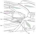
图9示出了一实施例的底盘和灌注构件组件;Figure 9 shows a chassis and perfusion member assembly of an embodiment;
图10示出了示出图9的实施例的力分布和操作的曲线图;Figure 10 shows a graph illustrating the force distribution and operation of the embodiment of Figure 9;
图11是图1(a)至1(c)所示的吸入器的分解立体图;Figure 11 is an exploded perspective view of the inhaler shown in Figures 1(a) to 1(c);
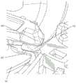
图12示出了吸入器的致动机构的底盘的另一实施例;Figure 12 shows another embodiment of the chassis of the actuating mechanism of the inhaler;
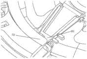
图13示出了吸入器的致动机构的底盘的另一实施例;Figure 13 shows another embodiment of the chassis of the actuating mechanism of the inhaler;
图14示出了吸入器的致动机构的灌注构件的另一实施例;Figure 14 shows another embodiment of the irrigation member of the actuation mechanism of the inhaler;
图15示出了吸入器的致动机构的灌注构件的另一实施例,Figure 15 shows another embodiment of the perfusion member of the actuation mechanism of the inhaler,
图16示出了灌注构件的悬臂叶片的一实施例;Figure 16 shows an embodiment of a cantilevered blade of a perfusion member;
图17示出了灌注构件的悬臂叶片的另一实施例,以及Figure 17 shows another embodiment of a cantilevered blade of a perfusion member, and
图18是示出了图12-17所示的致动机构的实施例的力分布和操作的曲线图。18 is a graph illustrating the force distribution and operation of the embodiment of the actuation mechanism shown in FIGS. 12-17.
图19示出了底盘的实施例,该底盘呈盘形联接至灌注构件,其中灌注构件具有成角度的悬臂,该悬臂具有间隙。Figure 19 shows an embodiment of a chassis coupled to an irrigation member in the shape of a disc, wherein the irrigation member has angled cantilevers with clearance.
图20示出了底盘的实施例,该底盘呈盘形联接至灌注构件,其中灌注构件具有成角度的三角形悬臂,该悬臂具有两个间隙。Figure 20 shows an embodiment of a chassis coupled to an irrigation member in the shape of a disc, wherein the irrigation member has an angled triangular cantilever with two gaps.
图21示出了底盘的实施例,该底盘呈盘形联接至灌注构件,其中灌注构件具有成角度的三角形悬臂,该悬臂具有两个间隙。Figure 21 shows an embodiment of a chassis coupled to an irrigation member in the shape of a disc, wherein the irrigation member has an angled triangular cantilever with two gaps.
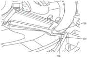
图22示出了图15的灌注构件,具有图17的悬臂叶片实施例。灌注构件联接到呈盘形的底盘的实施例。FIG. 22 shows the irrigation member of FIG. 15 with the cantilevered blade embodiment of FIG. 17 . An embodiment of a perfusion member coupled to a disc-shaped chassis.
图23示出了图22的底盘的底盘架子的成角度的倒角前缘的放大图。FIG. 23 shows an enlarged view of the angled chamfered leading edge of the chassis frame of the chassis of FIG. 22 .
图24示出了与图23的底盘架子接合的图22的悬臂叶片的尖端的放大图。FIG. 24 shows an enlarged view of the tip of the cantilever blade of FIG. 22 engaged with the chassis frame of FIG. 23 .
图25示出了悬臂叶片尖端在其与底盘架子的后缘接合时的运动。Figure 25 shows the movement of the cantilever blade tip as it engages the trailing edge of the chassis frame.
图26示出了悬臂叶片尖端在其与底盘架子的后缘接合时的运动,从而叶片可以在底盘架子下方移动。Figure 26 shows the movement of the cantilever blade tip as it engages the trailing edge of the chassis frame so that the blade can move beneath the chassis frame.
图27示出了悬臂叶片末端在其在底盘架子下方移动时的运动。Figure 27 shows the movement of the cantilever blade tip as it moves under the chassis frame.
图28示出了悬臂叶片尖端在其从底盘架子下方和底盘架子的成角度的倒角前缘移出时的运动。Figure 28 shows the movement of the cantilever blade tip as it moves out from under the chassis frame and the angled chamfered leading edge of the chassis frame.
此外,图中的物体之间的关系可能不是按比例的,并且实际上可能在尺寸上具有相反的关系。这些附图旨在使所示出的每个物体的结构变得理解和清楚,因此,一些特征可能被夸大以便示出结构的特定特征。Furthermore, the relationship between objects in the drawings may not be to scale and may actually be inversely related in size. The drawings are intended to enable understanding and clarity of the structure of each object shown, therefore some features may be exaggerated to show specific features of the structure.
具体实施方式Detailed ways
通过参考结合附图呈现的本公开的以下详细描述,可以更容易地理解本公开,所述附图一起构成了本公开的一部分。应当理解,本公开不限于本文描述和/或示出的特定装置、方法、条件或参数,并且本文所使用的术语出于仅通过示例描述特定实施例的目的,并非旨在限制要求保护的公开。呈现以下描述以使本领域的任何技术人员能够制造和使用本公开。The present disclosure can be understood more readily by reference to the following detailed description of the disclosure presented in conjunction with the accompanying drawings, which together form a part of this disclosure. It is to be understood that the present disclosure is not to be limited to the particular apparatus, methods, conditions or parameters described and/or illustrated herein, and that the terminology used herein is for the purpose of describing particular embodiments by way of example only and is not intended to limit the claimed disclosure. . The following description is presented to enable any person skilled in the art to make and use the present disclosure.
尽管阐述本申请的广泛范围的数值范围和参数是近似值,但在具体实例中阐述的数值被尽可能精确地报道。然而,任何数值都固有地包含某些误差,这些误差必定是由于它们各自的测试测量中的标准偏差而引起的。此外,应将本文公开的所有范围理解为涵盖其中包含的任何和所有子范围。例如,范围“1到10”包括最小值1和最大值10之间(包括端值)的任何和所有子范围,即最小值等于或大于1和最大值等于或小于10的任何和所有子范围,例如5.5到10。Notwithstanding that the numerical ranges and parameters setting forth the broad scope of the application are approximations, the numerical values set forth in the specific examples are reported as precisely as possible. Any numerical value, however, inherently contains certain errors necessarily resulting from the standard deviation found in their respective testing measurements. Moreover, all ranges disclosed herein are to be understood to encompass any and all subranges subsumed therein. For example, the range "1 to 10" includes any and all subranges between a minimum value of 1 and a maximum value of 10, inclusive, i.e. any and all subranges with a minimum value equal to or greater than 1 and a maximum value equal to or less than 10 , such as 5.5 to 10.
定义definition
如说明书中所使用并包括所附权利要求书,单数形式和“该”包括复数,并且除非上下文另有明确指示,否则对特定数值的引用至少包括该特定值。As used in the specification and including the appended claims, the singular and "the" include the plural, and references to a specific value include at least that specific value unless the context clearly dictates otherwise.
范围可以在本文中表示为从“约”或“近似”一个特定值和/或到“约”或“近似”另一特定值。当表达这样的范围时,另一实施例包括从一个特定值和/或至另一特定值。Ranges can be expressed herein as from "about" or "approximately" one particular value, and/or to "about" or "approximately" another particular value. When such a range is expressed, another embodiment includes from the one particular value and/or to the other particular value.
为了便于描述,使用诸如“下方”、“下面”、“下”、“上方”、“上”等的空间相对术语来解释一个元件相对于第二元件的定位。这些术语除了包含与图中所描绘的方位不同的方位外还旨在涵盖装置的不同方位。此外,诸如“第一”、“第二”等的术语也用于描述各种元件、区域、部分等,并且也不旨在进行限制。在整个说明书中,相似的术语指代相似的元件。For ease of description, spatially relative terms such as "below", "below", "lower", "above", "on" etc. are used to explain the positioning of one element relative to a second element. These terms are intended to encompass different orientations of the device in addition to orientations other than those depicted in the figures. In addition, terms such as "first", "second", etc. are also used to describe various elements, regions, sections, etc., and are not intended to be limiting. Throughout the specification, similar terms refer to similar elements.
如本文所用,术语“具有”、“包含”、“包括”、“含有”等是开放式术语,其指示所陈述的元件或特征的存在,但不排除其他元件或特征。As used herein, the terms "having", "comprising", "including", "containing" and the like are open-ended terms which indicate the presence of stated elements or features, but do not exclude other elements or features.
术语“药物”包括适于口服或鼻吸入的物质。药物可以包括活性药物成分和赋形剂。The term "medicament" includes substances suitable for oral or nasal inhalation. A drug can include active pharmaceutical ingredients and excipients.
术语“干粉吸入器”(DPI)是指以干粉形式将药物输送到肺部的装置。DPI通常用于治疗呼吸系统疾病,例如哮喘、支气管炎、肺气肿和COPD。DPI可以分为三种基本类型:i)散装粉末分配器,其保持足够的散装粉末以用于多剂量;ii)单剂量分配器,用于单剂量活性化合物的给药;以及iii)多剂量吸入器,其预装有足以更长治疗周期的有效成分。The term "dry powder inhaler" (DPI) refers to a device that delivers medication to the lungs in dry powder form. DPIs are commonly used to treat respiratory conditions such as asthma, bronchitis, emphysema, and COPD. DPIs can be divided into three basic types: i) bulk powder dispensers, which hold enough bulk powder for multiple doses; ii) single-dose dispensers, for the administration of a single dose of active compound; and iii) multi-dose dispensers. Inhalers that are prefilled with active ingredients sufficient for longer treatment cycles.
术语“定量吸入器”(MDI)指的是这样的装置:以通常由患者通过吸入自行给药的短时雾化的雾化药物形式向肺部输送特定量的药物。MDI通常用作治疗哮喘、慢性阻塞性肺疾病(COPD)和其他呼吸系统疾病的输送系统。The term "metered dose inhaler" (MDI) refers to a device that delivers a specific amount of drug to the lungs in the form of a short-duration aerosolized nebulized drug that is usually self-administered by the patient by inhalation. MDI is commonly used as a delivery system for the treatment of asthma, chronic obstructive pulmonary disease (COPD) and other respiratory diseases.
术语“容器”是指用于药物的容器。在一些实施例中,容器可具有一个或多个用于药物的袋。The term "container" refers to a container for a drug. In some embodiments, the container may have one or more pockets for medication.
术语“单位剂量”、“单位剂量接收器”和/或“剂量单位”是指包括一个或多个袋的容器,该袋包含配置成以特定剂量分配给患者的药物。The terms "unit dose", "unit dose receptacle" and/or "dosage unit" refer to a container comprising one or more bags containing a drug configured to be dispensed to a patient in a specific dose.
以下标题无意以任何方式限制本公开;任何一个标题下的实施例可以与任何其他标题下的实施例结合使用。The following headings are not intended to limit the disclosure in any way; embodiments under any one heading may be used in conjunction with embodiments under any other heading.
现在将详细参考本申请的某些实施例,其示例在附图中示出。尽管将结合图示的实施例描述本申请,但应当理解,它们并不旨在将本申请限制于那些实施例。Reference will now be made in detail to certain embodiments of the present application, examples of which are illustrated in the accompanying drawings. While the application will be described in conjunction with the illustrated embodiments, it will be understood that they are not intended to limit the application to those embodiments.
分配装置distribution device
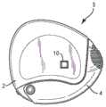
本申请提供了一种吸入装置,使用者可以从中吸入干粉形式的连续剂量药物。在图1(a)至1(c)中示出了实施例。该装置包括壳体2,衔嘴盖4可旋转地支撑在壳体2上。The present application provides an inhalation device from which a user can inhale continuous doses of a medicament in dry powder form. Embodiments are shown in Figures 1(a) to 1(c). The device comprises a
为了使用该装置,将衔嘴盖4旋转离开壳体2。如图1(b)所示,这暴露了衔嘴6。衔嘴6可以与壳体2一体地形成,然而,如下所述,它也可以形成为用于与壳体2安装的单独部件。这允许根据装置3的要求容易地改变衔嘴6和壳体2的材料特性,例如颜色。To use the device, the mouthpiece cover 4 is swiveled away from the
如图1(b)所示,灌注杆(priming lever)8在与衔嘴6相邻的位置处从壳体2延伸出。灌注杆8被安装成绕装置内的中心轴线旋转。这样,使用者可将其围绕壳体2的外围移动至如图1(c)所示的位置。灌注杆8从图1(b)所示的第一位置移动到图1(c)所示的第二位置布置成对装置进行灌注,特别是暴露一剂量粉末,使得可以用气流将其从衔嘴6中带出。As shown in FIG. 1( b ), a priming
应当注意的是,将灌注杆8的第一位置定位在邻近衔嘴6处是非常有利的,因为这会阻止使用者在将灌注杆8从衔嘴6移开至图1(c)的第二位置之前试图从衔嘴6吸入。换句话说,促使使用者在尝试通过装置吸入之前对其灌注。然而,应该注意的是,在衔嘴6和灌注杆8之间设置了很小的空间,以允许使用者用他或她的手指来操作灌注杆8而不会碰到衔嘴6。It should be noted that it is very advantageous to position the first position of the
在使用该装置之后,衔嘴盖4可以旋转回到图1(a)所示的其收起位置。在这方面,衔嘴盖4的内表面设置有用于与灌注杆8接合的返回致动器。特别地,当衔嘴盖4从图1(b)和1(c)的其打开位置移动到图1(a)的其关闭位置时,返回致动器与灌注杆8接合并将其从图1(c)所示的其第二位置移回到图1(b)所示的其第一位置。如将在下文中进一步描述,在一实施例中,灌注杆8的这种移动操作分度机构,用于将仍未使用和未打开的粉末袋移动成与分配机构对齐,从而在随后对装置进行灌注时,将那个袋的粉末分配用于吸入。通过在灌注和释放粉末袋后立即在灌注杆8的返回移动期间操作分度机构,如果未吸入释放的粉末,则将其分度至可以安全地保持在装置内的位置。After using the device, the mouthpiece cover 4 can be rotated back to its stowed position shown in Figure 1(a). In this respect, the inner surface of the mouthpiece cover 4 is provided with a return actuator for engagement with the priming
如图1(a)至1(c)所示,该实施例还包括在壳体2的一侧中的窗口10。窗口10设置成允许使用者观看装置内的计数器显示器。计数器机构在每次使用装置时对计数器显示器进行分度,以便向使用者提供已分配多少剂量和/或未使用多少剂量的指示。This embodiment also includes a
本申请的许多方面适用于容纳多种不同剂量托架的装置。特别地,以下描述的实施例的许多特征可以与具有传统泡罩包装构造的托架一起使用,其中托架具有各种阵列的袋,并且在一些布置中,一些托架具有单个相应袋。然而,当与图2(a)和2(b)所示的形式的托架一起使用时,本申请是有用的。Aspects of the present application are applicable to devices that accommodate a variety of different dose racks. In particular, many of the features of the embodiments described below may be used with trays having conventional blister pack configurations, with trays having various arrays of pockets and, in some arrangements, some trays having a single corresponding pocket. However, the present application is useful when used with brackets of the form shown in Figures 2(a) and 2(b).
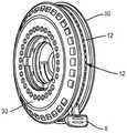
如图2(a)所示,每个托架12由盘形基部14形成,该盘形基部具有基本平面的第一侧表面16,其与基本平面的第二侧表面18相对并平行。多个通孔20形成在第一侧表面16和第二侧表面18之间,以形成用于容纳剂量粉末的空间。基部14形成有可观的厚度,以便为通孔20提供足够的空间来容纳所需剂量的粉末。通孔20布置成圆周阵列,并且在一实施例中,在该阵列中设置30个通孔。As shown in FIG. 2( a ), each
如图2(b)所示,基部14的第一和第二侧表面16、18分别用第一和第二盖片22、24密封。这样,托架12提供了容纳单独相应剂量粉末的多个袋。As shown in Figure 2(b), the first and second side surfaces 16, 18 of the base 14 are sealed with first and
如通过图3(a)和(b)的横截面所示,袋在每个通孔20内包括相应的插入件26。插入件26通常是杯形的,其开口端面向第一盖片22。每个插入件包含相应剂量粉末28。As shown in cross-section through FIGS. 3( a ) and ( b ), the bag includes a
通过从第二盖片24的侧面推动插入件26的封闭端,可以将插入件从托架12的基部14向外推动穿过第一盖片22。这在图3(b)中示出,但为了清楚起见,没有任何盖片。如图所示,在插入件26从基部14伸出的情况下,可更方便地提供气流(例如箭头所示)以从袋中去除粉末。By pushing the closed end of the
在一实施例中,在吸入装置的壳体2内,两个托架12如图4(a)所示同轴地并排布置。每个托架12设置有支撑件30,如图4(b)所示。在所示的实施例中,每个支撑件30定位成与其相应托架12的面向外的表面相邻。特别地,每个托架12的第一侧表面16面对相应的支撑件30,使得可以在两个托架12之间设置分配机构,以便将相应的袋插入件26(图3(a)和3(b))向外压向相应的支撑件30。下面将进一步描述该实施例的布置。In one embodiment, within the
如图所示,灌注杆8定位成使得其在托架12之间延伸并且可绕托架12的公共轴线旋转,从而操作分配机构和分度机构。As shown, the priming
在一实施例中,每个支撑件30由两个部件构成,即砧板32和气道板34。这些结合相关的托架12在图5(a)和(b)中示出。In one embodiment, each
每个砧板32具有平面表面36,在使用中,该平面表面36抵靠相关托架12的第一侧表面16,第一侧表面16被第一盖片22覆盖。每个砧板32还包括对应于相关托架12的通孔20的多个引导通孔38。Each
这样,如图6示意性所示,插入件26可从其通孔20中推出,并推入砧板32的相应的引导通孔38中。插入件26因此用于向外冲破第一盖片22,但仍牢固地保持在适当位置。尽管这里没有特别考虑,但砧板32也将第一盖片22支撑在通孔20周围,并且可以用于提高盖片破裂性质的可预测性。In this way, as schematically shown in FIG. 6 , the
如通过图7(a)的横截面所示,砧板32包括第二表面40,该第二表面邻靠相关气道板34的内表面。气道板34包括对应于相应砧板32的每个引导通孔38的一对通孔。特别地,每对包括入口孔42和出口孔44。As shown in cross-section through FIG. 7( a ), the
如图7(a)所示,相对于邻靠气道板34的内表面的砧板32的表面40,凹入通道46从出口44径向向内延伸,以便与砧板32的引导通孔38连通。因此,对于砧板32的每个引导通孔38,气道板34向其相关的凹入通道46提供与其连通的相应入口42和出口44。特别地,每个入口42与其相关的引导通孔38的一侧连通,同时相应的出口44与相关引导通孔38的相对侧连通。As shown in FIG. 7( a ), with respect to the
如图7(b)所示,当将插入件26从基部14的通孔20(图6)向外推入砧板32的引导通孔38中时,将其定位成其杯形的开口部分面向入口42(在杯形的一端)和凹入通道46(在杯形的相对端)。这样,如图所示,气流可以通过气道板34被吸入,从而使其向下进入插入件26中形成的袋中,返回到凹入通道46中,然后从出口44出来。因此,插入件26中的粉末被气流拾取,从插入件26中移出并被带出气道板34。因此,形成了进入和流出袋的流动路径,其随后可将袋连接至装置的衔嘴6。As shown in FIG. 7(b), when the
如图11所示,壳体2可以由一对外壳半部2a和2b形成。如图8(a)和8(b)所示,外壳半部2a和2b的内壁50与气道板34配合,以形成通向衔嘴6的第二流动路径,其绕过袋。可替代地,可以提供附加部件以限定第二流动路径。As shown in FIG. 11, the
如图8(b)所示,对于由插入件26形成的每个袋,气道板34的相应入口42位于袋的周边附近。相应出口44设置在袋的相对侧上,使得入口42和出口44之间的气流穿过袋,因此从袋中拾取任何粉末。如图所示,入口42形成为向下指向形成袋的插入件26的一部分。As shown in Figure 8(b), for each pocket formed by
这样,当使用者通过该装置吸入并产生通过其的气流时,通过入口42吸入的气流将被向下引导到插入件26中的任何粉末中,以将其移出并移动到该气流中以便被带到出口44之外。在所示的实施例中,将袋的体积连接到出口44的凹入通道46位于邻近入口42。这样,来自入口42的气流从插入件26的基部(及那里的任何粉末)偏转,以便朝向凹入通道46返回。气流中携带的粉末进入凹入通道46在方向上经受相对剧烈的变化。结果,气流中的粉末易于分散。此外,粉末将趋于撞击凹入通道46的表面,这也有助于分散。In this way, when a user inhales through the device and generates an airflow therethrough, the airflow inhaled through the
如图8(b)清楚地示出,选择气道路径的形状以迫使较大的粉末聚集团在气流被迫改变方向时撞击壁,从而分散大块粉末。该形状的设计还可以确保将气道内任何表面上的空气流动保持在较高值,以避免过多的粉末附着在表面上。因此,拐角是圆形的,并且沿管的每个位置处的横截面设计为保持空气速度而不会产生过多的压降。As clearly shown in Figure 8(b), the shape of the airway path is chosen to force larger agglomerates of powder to strike the walls when the airflow is forced to change direction, thereby dispersing large pieces of powder. The shape is also designed to ensure that the air flow over any surface within the airway is kept at a high value to avoid excessive powder deposition on the surface. Therefore, the corners are rounded and the cross-section at each location along the tube is designed to maintain air velocity without creating excessive pressure drop.
如图8(a)所示,在该实施例中,通过袋的气流在通向袋的入口处具有由尺寸“A”限定的其最小面积,而绕过袋的气流恰好在气流加入之前具有其最小横截面,因此由尺寸A定义。As shown in Figure 8(a), in this embodiment the airflow through the bag has its smallest area defined by dimension "A" at the inlet to the bag, while the airflow around the bag has Its minimum cross-section is therefore defined by dimension A.
在横截面积最小的地方,空气速度最高,因此这种布置提供高速空气以从袋中提取粉末,并利用加入袋中气流包含的粉末的旁路空气的高速,以帮助分散并保护壁免于粉末沉积。Air velocity is highest where the cross-sectional area is smallest, so this arrangement provides high velocity air to extract the powder from the bag and utilizes the high velocity of bypass air that joins the powder contained in the airflow in the bag to help disperse and protect the walls from Powder deposition.
通过袋的气流速度主要受使用者吸入时产生的吸气压力控制,而体积流量既是速度又是面积的因素。The velocity of the airflow through the bag is primarily controlled by the inspiratory pressure generated by the user inhaling, while the volumetric flow rate is a factor of both velocity and area.
应该产生足够高的空气速度以确保粉末被夹带在气流中。然而,如果速度和流量太高,则可能会将袋中的整个粉末团以凝聚团块的形式推入气道。如果发生这种情况,团块可能无法加速到足够的速度以使其与气道中的壁碰撞而使其破裂并提供分散。据信粉末通过气流从袋中逐渐移除。为此,在袋中粉末的表面与由入口42和凹入通道46之间的气道板34中的分隔部分形成的气道顶板之间设置小间隙46a。这与限制通过袋的流量的“A”的尺寸结合一起确保粉末从袋中被减少而不是被推出。A sufficiently high air velocity should be generated to ensure that the powder is entrained in the air stream. However, if the velocity and flow are too high, the entire mass of powder in the bag may be pushed into the airway in agglomerated clumps. If this happens, the clumps may not accelerate enough to collide with walls in the airways to break them apart and provide dispersion. It is believed that the powder is gradually removed from the bag by air flow. To this end, a small gap 46a is provided between the surface of the powder in the bag and the airway ceiling formed by the partition in the
为此,对于宽度约为2.0mm(沿圆周方向)和长度约为7.3mm(沿径向方向)的袋,将入口孔直径“a”选择在0.5mm至2.0mm之间。选择的值取决于粉末的性质。To this end, the inlet hole diameter "a" is chosen between 0.5 mm and 2.0 mm for a bag with a width of approximately 2.0 mm (in the circumferential direction) and a length of approximately 7.3 mm (in the radial direction). The chosen value depends on the nature of the powder.
这样,可以在0.1秒至1.0秒之间的时间段内从袋中取出粉末。这在吸入周期的高流速期间内,并提供粉末的良好分散。In this way, the powder can be removed from the bag within a time period between 0.1 second and 1.0 second. This provides good dispersion of the powder during the high flow rate of the inhalation cycle.
应当理解,在其他实施例中,除了入口孔之外,穿过袋的流动路径的部分,例如在粉末的下游,可形成该流动路径的最小横截面。入口孔的直径“a”仍将采用类似的考虑。It should be understood that in other embodiments, the portion of the flow path through the bag other than the inlet aperture, for example downstream of the powder, may form the smallest cross-section of the flow path. The diameter "a" of the inlet hole will still be subject to similar considerations.
入口孔42和通道46的布置与深而窄的粉末袋相结合是特别有利的。在特定的流速下,例如10升/分,粉末表面将被减少一定深度。将流速提高到例如20升/分,将导致粉末被减少更深的深度。由于使用者吸入会导致流速逐渐增加到最大,因此粉末会随着深度而逐渐减少,并且在适当的时间段内会逐渐排空袋。The arrangement of inlet holes 42 and
尽管使用者的吸入量和强度会有所不同,但重要的是,该装置不应提供太多的吸入阻力。在这方面,通过具有期望横截面积的入口42吸入可能会是极其困难的。实际上,在可能的情况下,这将导致太高的流速,并且太快地夹带来自插入件26的所有粉末。在实践中,发现大约只有20%的吸入空气可直接用于粉末的拾取和分散。While the volume and strength of inhalation varies among users, it is important that the device does not provide too much resistance to inhalation. In this regard, suction through an
如图8(b)所示,在壳体2的内壁50和气道板34的外部之间形成第二流动路径。第二流动路径绕过袋并增加了可用于吸入的总横截面积。通过更改尺寸a和A的值,可以改变袋和旁路之间的气流速率,并控制装置的整体流阻,从而使使用者吸入舒适。对于601/min的流量,该装置的典型流阻在2kPa至5kPa之间。对于较难分散的粉末,选择较高的流阻,而对于儿童使用的装置则使用较低的流阻。凹入通道46和出口44通常具有比入口42大的横截面积。可以想到的是,袋路径的最小横截面积为3.5mm2至4.0mm2,而旁路为5.0mm2至6.0mm2。As shown in FIG. 8( b ), a second flow path is formed between the
这样,由于大部分气流将通过第二流动路径,因此相对容易地通过装置吸入。然而,如上所述,一些流动将通过第一流动路径发生,以便夹带和分散粉末。In this way, it is relatively easy to draw through the device since most of the airflow will be through the second flow path. However, as mentioned above, some flow will occur through the first flow path in order to entrain and disperse the powder.
在一实施例中,对于装置的另一侧及其对应的托架具有另一第二流动路径。在使用中,患者通过两个第二流动路径吸入,同时从第一流动路径吸取粉末。预期每个第二流动路径携带约40%的总吸入空气。In an embodiment, there is another second flow path for the other side of the device and its corresponding tray. In use, the patient inhales through the two second flow paths while aspirating powder from the first flow path. Each second flow path is expected to carry approximately 40% of the total intake air.
实际要求将根据粉末的性质和目标使用者而有所不同。对于易于分配的粉末,形成通向袋的入口的部分可能很小,而对于患有COPD(慢性阻塞性肺疾病)的儿童或患者,总压降应较低。在这种情况下,入口部分可具有2mm2的横截面积和最小横截面积为8mm2的旁通第二流动路径,其比率为25%。另一方面,对于用于健康成年人的粘性粉末,入口部分可具有4mm2的横截面积以及最小横截面积为6mm2的旁通第二流动路径,其比率为66%。当然,中间值也是可能的,并且有用的布置具有约3mm2的入口部分且第二流动路径的最小横截面积为6mm2,其比率为50%。Actual requirements will vary depending on the nature of the powder and the intended user. For powders that are easy to dispense, the portion forming the inlet to the bag may be small, while for children or patients with COPD (chronic obstructive pulmonary disease) the total pressure drop should be low. In this case, the inlet portion may have a cross-sectional area of 2 mm2 and a bypass second flow path with a minimum cross-sectional area of 8 mm2 with a ratio of 25%. On the other hand, for a cohesive powder intended for healthy adults, the inlet portion may have a cross-sectional area of 4 mm2 and a bypass second flow path with a minimum cross-sectional area of 6 mm2 , a ratio of 66%. Of course, intermediate values are also possible, and a useful arrangement with an inlet portion of about 3 mm2 and a minimum cross-sectional area of the second flow path of 6 mm2 is a ratio of 50%.
如图8(a)所示,出口44的壁被定向成以相对于第二流动路径中的流动成角度θ将空气和粉末的流动引导到第二流动路径中。通过确保角度θ小于45°,可以显著减少可能撞击或粘附在与出口44相对的壁50上的粉末量。在一些实施例中,角度θ不大于45°,且在其他实施例中,不大于30°。这样,基本上没有粉末将附着到形成通向衔嘴6的第二流动路径的壁50上。在一些方面,在重复使用该装置的情况下,不超过25%(在其他方面,不超过15%)的剂量保持沉积在壁50上。在这方面,将理解的是,来自旁路的通过壁50的流动将起到冲刷或清除壁50上的粉末的作用。As shown in Figure 8(a), the walls of the
如以上参考图5(b)所提到,砧板32和气道板34一起形成用于相应托架12的支撑件。借助于灌注杆8和下面将要描述的分度机构,将支撑件30及其对应的托架12移动到从连续袋分配粉末的连续位置。在这方面,将理解的是,每个袋具有如在气道板34中形成的其自己的第一流动路径。根据以上描述,将理解的是,在从袋中移出粉末和分散粉末时的湍流发生在第一流动路径内。因此,如果任何粉末粘附到气道板34内的壁上,则在分配随后的粉末袋时该粉末不会被吸入。As mentioned above with reference to FIG. 5( b ), the
在一些实施例中,装置布置成使得提供空气流动通过袋和通过旁路的入口通道布置成使得其仅将空气进给至定位用于分配的袋,例如在图8(a)和8(b)中所示。使用后,托架12、砧板32和气道板34的分度将对于用过的袋的入口42和出口44重新定位在用于当前使用的袋的气流之外。In some embodiments, the device is arranged such that the inlet channel providing air flow through the bag and through the bypass is arranged such that it only feeds air to the bag positioned for dispensing, for example in Figures 8(a) and 8(b ) shown in . After use, the indexing of the
这种布置确保即使打开袋后来自袋中的粉末都没有移出,一旦将其分度(index),则粉末将永久保留在装置内,从而其不会与随后剂量一起吸入。This arrangement ensures that even after the bag is opened, no powder is removed from the bag, once it is indexed, the powder remains permanently within the device so that it cannot be inhaled with subsequent doses.
支撑件30和相关托架12可以借助于底盘组件58可旋转地安装在壳体2内,如图9所示。底盘组件58位于托架12的第二侧表面18之间。其沿着托架12的轴线轴向延伸,并且固定到壳体2的两个半部2a、2b之一或两个。The
如图9所示,灌注杆8构成灌注构件60的一部分(或可以附接到其上)。灌注构件60具有中心枢转开口62,通过其将灌注构件60可旋转地支撑在底盘66的枢转轴64上。As shown in FIG. 9 , the
参考图9和11,灌注构件60和底盘66一起作为致动机构52定位在两个托架12与相关支撑件30a和30b之间。此外,底盘66安装至壳体2,以便可旋转地固定。在所示的实施例中,枢转轴64本身可以位于设置在壳体2的一个或两个半部2a、2b的内侧上的轴68(图11中所示)上。而且,径向延伸部70(图9中所示)可以设置在底盘66上以与壳体2的内部相互作用,从而可旋转地固定底盘66。托架12和相关支撑件30a和30b可以可旋转地安装在底盘66上。Referring to Figures 9 and 11, the
灌注构件60包括沿圆周方向延伸的细长凸轮构件72,并且在两个相对侧的每个上具有凸轮表面74。
每个凸轮表面74与将被描述为刺棒的相应构件76相互作用。Each
如图9所示,灌注构件60包括在凸轮构件72的任一侧上的细长开口79,刺棒76的臂80可以延伸穿过该细长开口。底盘66可旋转地保持刺棒76,但允许它们沿装置的轴向方向移动,换句话说,朝向或远离任一侧上的托架12。实际上,如图所示,在底盘66中存在孔69,其允许刺棒76之一穿过底盘66朝向相应的托架12延伸。As shown in FIG. 9 ,
参照图2(a),可以看到,在一方面,托架12具有通孔20阵列,其包括其中未形成通孔20的空白部分82。Referring to FIG. 2( a ), it can be seen that, in one aspect, the
使用这种类型的托架,可以将一个托架12定位成空白部分82与刺棒76相对,同时围绕着其通孔20中的每个和它们形成的袋连续地对另一托架12进行分度,直到全部被排空。分度机构然后可以将空托架旋转到其空白部分82与刺棒76相对的位置,并使另一托架12绕着相应刺棒与通孔20对准的所有位置旋转。这样,相同的分配机构用于从两个托架分配粉末并使用相同的操作。Using this type of bracket, it is possible to position one
尽管意图是通过吸入将从各个袋中分配的基本所有粉末从装置中移出,但有可能一些粉末会残留在装置内。实际上,在使用不同类型的托架或装置具有不同应用的情况下,可能是在装置内确实残留了更多的粉末。Although it is intended that substantially all of the powder dispensed from each pouch is removed from the device by inhalation, it is possible that some powder may remain within the device. In fact, where a different type of carrier is used or the device has a different application, it may be that more powder does remain inside the device.
如图9所示,凸轮表面74设置有一个或多个凹槽或通道84。任何过量的粉末因此可以落入凹槽或通道84中,从而不会阻碍凸轮表面74和刺棒76之间的接触和运动。As shown in FIG. 9 , the
在图9中详细示出的致动机构52布置在托架12的底表面之间。致动机构52适于暴露一个单位剂量28干粉末,使得每次致动灌注杆8时,它可以随气流被带出衔嘴6。An
特别地,致动机构52包括:分配机构,其适于将每个单位剂量28暴露于相应的流动路径;以及分度机构,其适于使每个流动路径与衔嘴6连通。In particular, the
致动机构52包括盘形底盘66,其支撑分配机构和分度机构。底盘固定至外壳2,并且包括装配在外壳2的轴68上的中空枢转轴64。在一位置处,底盘包括引导构件71,其轴向延伸并在它们之间限定径向孔。底盘66还设置有径向延伸部70,其与壳体2的内部相互作用以旋转地固定底盘66。The
致动机构52还包括灌注构件60,其支承灌注杆8并且可绕中心轴线A旋转,从而在致动灌注杆8时操作分配机构和分度机构。The
在WO-A-2005/002644中公开了合适的灌注构件60的示例。灌注构件60由盘形板形成,该盘形板由塑料模制而成并具有中心枢转开口62,通过该枢转开口其可旋转地支撑在底盘66的枢转轴64上。An example of a
在所示的实施例中,分配机构适于将每个托架12的每个袋插入件26从其存储位置移动到其排出位置。此外,在WO-A-2005/002644中公开了一种合适的分配机构的示例,其实施安装在灌注构件60上的刺棒76以及布置在灌注构件60上并适于轴向移动刺棒76的凸轮表面74、73。In the illustrated embodiment, the dispensing mechanism is adapted to move each
特别地,分配机构包括细长凸轮构件72,其形成在灌注构件60上并且通过底盘66的引导构件71延伸穿过的凹槽或通道84与灌注构件60的其余部分分开。凸轮构件72在圆周方向上延伸并且具有适于提供有限量的挠性的轮廓。中心凸轮表面74设置在凸轮构件72的两个相对侧的每个上。此外,侧向凸轮表面73、75在灌注构件60的任一侧上沿着与凸轮构件72相对的细长开口79在圆周方向上延伸。In particular, the dispensing mechanism includes an
刺棒76彼此相同,并且在它们之间与凸轮构件72夹在一起。每个刺棒76具有垂直于中心部分延伸的臂80,中心部分布置成与凸轮构件72的中心凸轮表面74配合。臂80延伸穿过灌注构件60的细长开口79,并且具有布置在其端部以接触灌注构件60的侧向凸轮表面73的特征80a。The
灌注构件60的细长凸轮开口79和凹槽或通道84以及底盘66上的引导构件71布置成旋转地保持刺棒76,但是借助于积极引导刺棒76的中心凸轮表面74和侧向凸轮表面73,从而使它们在装置3的轴向方向上朝向和远离托架12移动。The
如在WO-A-2005/002644中解释,致动机构52布置为刺棒76之一与相应托架12的插入件26之一对准,而另一刺棒76面向另一托架12的空白部分82。这样,分配机构一次仅分配托架12之一的一个单位剂量28。As explained in WO-A-2005/002644, the
现在描述分配机构的操作。The operation of the distribution mechanism will now be described.
如图11所示,灌注杆8在外壳2b的狭槽11中沿其行程从靠近衔嘴6的第一位置移动到与衔嘴6相距一定距离的第二位置对吸入器1进行灌注,以使单位剂量28干粉末28暴露于相应的流动路径。As shown in FIG. 11 , the
在初始步骤,当使用者移动衔嘴盖4以露出衔嘴6时,灌注杆8处于其第一位置,并且两个刺棒76均在凸轮构件72的与中心凸轮表面74相对的一端处处于缩回位置。In an initial step, when the user moves the mouthpiece cover 4 to expose the mouthpiece 6, the priming
当使用者将灌注杆8移动到其第二位置时,灌注构件60相对于底盘66旋转。凸轮构件72的凸轮表面74分别接合刺棒76。与插入件26之一对准的刺棒76接合的凸轮表面74压出刺棒76,从而刺棒76朝向其相应托架12向外移动,刺穿托架12的通孔20并将插入件26推到排出位置。同时,与空白部分82对准的刺棒76接合的凸轮表面74由于其挠性而变形。When the user moves the priming
在使用者吸入单位剂量28之后,使用者可以将衔嘴盖4旋转回。衔嘴盖4的致动肋可以接合灌注杆8以将其移回到其第一位置。灌注构件60的侧向凸轮表面73使刺棒76缩回。After the user has inhaled the
现在将描述分度机构。The index mechanism will now be described.
在图11所示的实施例中,分度机构适于使第一支撑件30a和第二支撑件30b在相继的活动位置移动,在每个活动位置,流动路径之一连接至衔嘴6,从而气流可以通过衔嘴6携带相应的单位剂量28。在WO-A-2005/002644中公开了一种实施间歇运动机构的合适的分度机构的示例。In the embodiment shown in Figure 11, the indexing mechanism is adapted to move the
特别地,如图9所示,分度机构包括绕着平行于中心轴线A的轴线可旋转地安装在外壳2内的槽轮100。槽轮100包括适于与灌注构件60配合的钉轮77,以使得每次致动灌注杆8时槽轮旋转120°的角度。槽轮100还包括与钉轮77同轴并适于分别与第一支撑件30a和第二支撑件30b的联接部分配合的两个齿轮78。钉轮77具有三个长钉102和三个短钉103,它们围绕其边缘以60°的间隔交替布置。In particular, as shown in FIG. 9 , the indexing mechanism comprises a
分度机构还包括形成在灌注构件60的外边缘上的驱动构件81。驱动构件81布置成使得当灌注杆8如上所述从其第一位置移动到其第二位置时,分配机构将袋插入件26(未示出)推到排出位置,驱动构件81不使槽轮100旋转,当灌注杆8从其第二位置移回到其第一位置时,驱动构件81使槽轮100旋转。特别地,驱动构件81在圆周方向上放置在与灌注构件60的包括分配机构的部分相邻的位置。The indexing mechanism also includes a
驱动构件81设置有依序布置的前部101、朝向前部101向下倾斜的棘轮棘爪83以及具有后缘85的狭槽83a。现在将针对由灌注杆8在由使用者致动时的运动限定的一个周期来描述分度机构的操作。在以下描述中针对一个周期使用与长钉102和短钉103相关的术语“第一”、“第二”和“第三”。应当理解,“第一”、“第二”和“第三”钉将在随后的周期中改变。The
如上所述,当灌注杆8从其第一位置移动到其第二位置时,驱动构件81不使槽轮100旋转。特别地,钉轮77和驱动构件81布置成使得灌注构件60的外边缘越过第一短钉103并在第一短钉103的任一侧上相邻的第一和第二长钉102上滑动,棘轮棘爪83在越过第二短钉103时变形。因此,防止槽轮100旋转。As mentioned above, the
当灌注杆8从其第二位置返回到其第一位置时,前部101越过第一短钉103,并且灌注构件60的外边缘在第一和第二长钉102上滑动,从而防止钉轮77旋转。然后,棘轮棘爪83与第一短钉103接合,从而使钉轮77被驱动,第二长钉102进入狭槽83a。当棘轮棘爪83脱离第一短钉103时,狭槽83a的后缘85与第二长钉102接合并继续驱动钉轮77。当狭槽83a的后缘85脱离第二长钉102时,灌注构件60的外边缘越过与第二长钉102相邻的第二短钉103,并邻接第二和第三长钉102。每次致动灌注杆4时,分度机构使每个托架12之一增加一个单位剂量28。When the
每个气道板34的联接部分的齿轮齿35可以与槽轮100的相应齿轮78接合,以便相继地在活动位置相对于外壳2移动。气道板34上的齿轮齿35的数量和齿轮78布置成使得槽轮100的120°的角度的运动使支撑件30a或30b恰好增加一个螺距。The
为了避免同时驱动第一支撑件30a和第二支撑件30b,首先使分度机构驱动第一支撑件30a,并且在这已经分配了全部其单位剂量28时则驱动第二支撑件30b。In order to avoid driving the
上述实施例布置成从一个托架12的每个插入件26分配干粉末,然后从另一托架12的每个插入件26分配干粉末。然而,应当理解,装置也可以交替地从一个托架12然后从另一托架12分配来自插入件26的干粉末。可替代地,两个托架的插入件26可以同时分配。The embodiments described above are arranged to dispense dry powder from each insert 26 of one
应当理解,对于一个或其他刺棒76抵靠在没有袋的托架12的空白部分82上以便使灌注构件60旋转并且凸轮构件72使刺棒76朝向另一托架12移动的布置,将需要使凸轮构件72远离空白部分82移动。在一些实施例中,有可能允许整个灌注构件60轴向移动或托架12轴向移动。然而,在一实施例中,凸轮构件72自身具有有限量的挠性。如图所示,凸轮构件72被设置为细长构件,其在每个端部处附接至灌注构件60的其余部分,在其任一侧具有细长开口。这将允许凸轮构件72具有足够的挠性以朝向和远离托架12移动。It will be appreciated that for an arrangement in which one or the
考虑如参照图1(a)至(c)所描述的整体实施例,应当理解,非常需要确保使用者移动灌注杆8移动通过其整个行程,以便完全分配剂量粉末。特别地,使用者不希望部分地操作灌注杆8和灌注构件60,以使得刺棒76将插入件26推到足够远以部分地破裂第一侧表面16上的盖片,而没有将插入件26完全延伸到图6和7(b)中所示的位置。Considering the overall embodiment as described with reference to Figures 1 (a) to (c), it will be appreciated that it is highly desirable to ensure that the user moves the
在图9所示的实施例中,通过灌注构件60的灌注杆8与分度槽短销103的接合来启动分度机构;分度槽轮100的旋转使托架盘前进到下一剂量位置并且使计数器递减1。在此应用中,装置3中的灌注构件60上的灌注杆8在致动和分度时都遵循相同的路径,并且使用棘轮动作以在致动行程上跳过分度槽短销103。灌注构件60所遵循的路径在整个致动步骤(包括分度和计数)中都在底盘下方。In the embodiment shown in Figure 9, the indexing mechanism is activated by engagement of the
由于插入件26的运动受到第一和第二盖片或箔22、24的限制,从而密封托架板12的两个表面,因此需要高的力来使插入件26开始移动。该力增大到箔22、24破裂的点,此后力显著减小。因此,使用者在其行进的早期就对灌注杆8的运动感到阻力。在沿其行进的某个点,随着箔22、24的破裂,阻力突然减小。使用者不能立即减小所施加的力,从而使灌注杆8被快速推到其可用行程的末端。这种触觉反馈鼓励使用者完全打开袋。Because the movement of the
以这种方式,使用可以使用常规材料和模制过程制造的部件来实现袋的可靠打开。In this way, reliable opening of the bag is achieved using components that can be manufactured using conventional materials and molding processes.
在一实施例中,两个托架组件的分度(图5(a)和(b))是通过分度机构和转换机构完成的,分度机构使得每次致动灌注杆8时托架12增加一个袋,转换机构使分度机构最初驱动第一托架12,但当已经使用该托架12的最后袋时,该托架12保持静止,而当致动分度机构时第二托架12增加。In one embodiment, the indexing of the two carriage assemblies (Fig. 5(a) and (b)) is accomplished by means of an indexing mechanism and a switching mechanism, the indexing mechanism allowing each time the
在WO-A-2005/002644中描述的有用的分度机构使用3钉槽轮100,其在每次致动分度机构时精确地旋转120°。槽轮100具有与槽轮同轴的两个齿轮,布置成使得齿轮可以与气道板34上的齿35接合。A useful indexing mechanism described in WO-A-2005/002644 uses a 3-
为了避免两个气道板34被同时驱动,布置成在气道板34周围的一个位置缺少齿轮齿35。结果,在该位置,槽轮100的旋转不会使气道板34旋转。因此,分度机构经由槽轮100及其齿轮驱动第一托架12,直到其到达该托架12的齿轮齿35的端部。下一个分度将第一托架12移动到其非驱动位置,即缺少齿轮齿35的位置,并接合转换机构,该转换机构旋转第二托架12,直到其齿轮35与槽轮100上的齿轮接合。In order to avoid that the two
旋转灌注构件60在单个模制部件内结合许多先前描述的功能元件。它包括灌注杆8、凸轮构件74、刺棒76和棘轮83,并且是用于对槽轮100进行分度的驱动构件。The
如前所述,为了使该装置与两个盘托架板一起工作,在某些应用中,提供转换机构,以使分度机构首先驱动第一盘,并且在这已经打开其所有袋时则驱动第二盘。这种转换机构在WO-A-2005/002644中进行了描述,其全文以引用的方式并入本文。转换机构允许相同的分度机构首先对第一托架盘进行分度,然后在预定位置对两个托架盘一起分度一个增量,然后随后使分度机构仅对第二托架盘进行分度。转换动作可以仅通过第一托架盘的角位置启动,不需要使用者的其他输入并且在触觉反馈中提供不明显的差异。在一实施例中,两个托架组件的分度(图5(a)和(b))是通过分度机构和转换机构完成的,分度机构使托架12在每次致动灌注杆8增加一个袋,如图11所示,转换机构90使分度机构最初驱动第一托架12,但是当已经使用了该托架12的最后袋时,该托架12保持静止,而当分度机构被致动时第二托架12增加。例如,在图9中可见的外壳135可以与致动机构52的底盘66一体形成,以可旋转地支撑转换机构的部件。As previously stated, in order for the device to work with two disc carrier plates, in some applications a switching mechanism is provided so that the indexing mechanism first drives the first disc, and when this has opened all its pockets then Drive the second disk. Such a conversion mechanism is described in WO-A-2005/002644, which is hereby incorporated by reference in its entirety. The switching mechanism allows the same indexing mechanism to first index the first tray, then index both trays together one increment at a predetermined position, and then subsequently cause the indexing mechanism to index only the second tray Graduation. The shifting action can be initiated only by the angular position of the first tray plate, requiring no other input from the user and providing an unnoticeable difference in tactile feedback. In one embodiment, the indexing of the two carriage assemblies (Figure 5(a) and (b)) is accomplished by an indexing mechanism and a switching mechanism, the indexing mechanism enables the
在图9中还示出的夹子125提供互锁,其防止任何摩擦联接导致两盘装置的上气道板在下气道板到达正确位置之前移动。
因此,自动实现从一个盘的分度到另一盘的分度转换,并且部件数量最少且占用空间非常小。Thus, the indexing changeover from one disc to the other is automatic, with a minimum number of parts and a very small footprint.
在一些方面,除了使下一个袋与刺棒76对准之外,该装置的分度还致动剂量计数器,其向使用者提供视觉指示剩余剂量的数量。用于图9中所示的实施例的有用剂量指示器的操作在WO-A-2005/002644中描述。In some aspects, in addition to aligning the next pocket with
当分配药物时,该装置向使用者指示该装置中剩余的剂量数量是有用的。这样的指示易于阅读也是有用的,因此,非常小的数字指示剩余剂量将是不利的。在包含60个剂量的袋便携装置的尺寸限制内,提供这样的显示器是具有挑战性的。When dispensing medicament, it is useful for the device to indicate to the user the number of doses remaining in the device. It would also be useful for such an indication to be easy to read, therefore a very small number indicating the remaining dose would be disadvantageous. Providing such a display is challenging within the size constraints of a pouch-portable device containing 60 doses.
在案例中,用通过窗口可见的数字标记托架盘的最简单布置需要在使用两个托架盘的情况下使用者查看不同的窗口,此外,托架盘周围的可用空间意味着数字的大小会很小。In the case, the simplest arrangement of marking the pallet discs with numbers visible through the windows requires the user to look at different windows in case two pallet discs are used, moreover, the available space around the pallet discs means the size of the numbers will be small.
有用的方法是采用具有独立单位和十位指示的显示器,驱动该显示器以使十位显示分度作为从9到0的单位显示分度。这允许在同一案例中使用更大的数字。两个盘可以彼此同心地设置,并且在某些情况下,与装置的轴线同轴地设置,例如在图11所示的轴68上。通过图1(a)所示的窗口10可以看到显示的单位和十位。除了将下一个袋插入件26移动成与刺棒对准之外,装置的分度还致动计数器机构140,其向使用者提供视觉指示已经分配了多少单位剂量28和/或多少个单位剂量28还未使用。在WO-A-2005/002654中描述了合适的计数器机构140的示例,其实现了由与分度机构的槽轮100的齿轮78之一啮合的驱动齿轮驱动的单位和十位计数器。当计数器显示器9的单位显示器从9分度到0时,驱动齿轮以及单位和十位计数器适于分度一个数字的计数器显示器9的十位显示器。A useful approach is to use a display with separate units and tens indications, which is driven so that the tens display divisions display divisions as units from 9 to 0. This allows larger numbers to be used in the same case. The two discs may be positioned concentrically with each other and, in some cases, with the axis of the device, for example on shaft 68 shown in FIG. 11 . The displayed unit and tens can be seen through the
在一实施例中,显示器倒数至零,但是十位盘不具有“0”。相反,它配备有指示器,例如符号或彩色灯,以向使用者指示该装置即将达到其功能寿命。In one embodiment, the display counts down to zero, but the tens dial does not have a "0". Instead, it is equipped with indicators, such as symbols or colored lights, to indicate to the user that the device is approaching the end of its functional life.
一实施例使用由托架盘的运动驱动的另一槽轮和齿轮装置。指示的是,首先通过第一托架盘的运动然后通过第二托架盘的运动来增加单个计数器,使得该装置包含两个托架盘的事实对于使用者而言是不明显的。One embodiment uses another sheave and gear arrangement driven by the movement of the carriage plate. It is indicated that a single counter is incremented first by movement of the first tray and then by movement of the second tray so that the fact that the device contains two trays is not obvious to the user.
使用完最后剂量后,剩余剂量显示将读为0,向使用者指示装置是空的。然而,如果使用者不看显示器,则当需要更多剂量时,他们可再次致动装置。合适的装置在被致动时将为使用者提供一些肯定的反馈,表明它是空的。After the last dose has been used, the remaining dose display will read 0, indicating to the user that the device is empty. However, if the user is not looking at the display, they can actuate the device again when more doses are required. A suitable device, when actuated, will provide the user with some positive feedback that it is empty.
该反馈的形式可以是,灌注杆8不能以通常使用的力水平移动到其操作位置。这种触觉反馈提供了封锁特征。This feedback can be in the form that the
用两个盘装置实现此的有用方法是布置成在使用最后剂量后,第二盘分度,以使其在刺棒下没有袋。在该点处,两个刺棒构件76都面对着没有袋的盘的表面。因此,当灌注杆8移动时,刺棒构件76都不能移动到盘上,并且在刺棒构件76上的合力通过驱动机构传递回到灌注杆8,从而传递给使用者。A useful way to achieve this with a two disc arrangement is to arrange that after the last dose is used, the second disc is indexed so that there is no pocket under the prod. At this point, both prod
尽管使用者可能能够施加足够的力以将灌注杆8移至其原始位置,但这仅通过迫使盘克服箱体的约束而分开是可能的。这样做所需的力可以足够大,以使正常的致动力对使用者来说是显而易见的。Although the user may be able to apply sufficient force to move the
吸入装置可能并且有时被误用。例如,在使用者没有将灌注杆基本推到行程末端的情况下,从该点返回将使盘前进至下一剂量并使计数器递减,即使尚未提供可吸入的剂量。这发生在整个行程的大约三分之一,即在打开袋之前。Inhalation devices can and are sometimes misused. For example, without the user pushing the priming rod substantially to the end of the stroke, returning from that point will advance the disc to the next dose and decrement the counter, even though no inhalable dose has yet been delivered. This happens about a third of the way through, before opening the bag.
在误用情况下,致动步骤不能轻易地在误用区域中暂停。如果在打开袋之前返回了灌注杆,则即使没有输送剂量,装置也会分度并计数。可以在多个致动周期中重复这种行为。结果,该装置在整个误用区域均具有上升力,如图10所示。In case of misuse, the actuation step cannot easily be suspended in the misuse area. If the priming rod is returned before the bag is opened, the device will index and count even if no dose is delivered. This behavior can be repeated over multiple actuation cycles. As a result, the device has a lift force throughout the misuse area, as shown in Figure 10.
为了通过不完全致动灌注杆或不遵循使用说明书来减少或甚至消除吸入器误用的可能性,可以改善致动机构的底盘和灌注构件的几何形状。例如,用于吸入器的致动机构的底盘的其他实施例在图12和图13中示出。在图14和15中示出了致动机构的灌注构件的其他实施例。In order to reduce or even eliminate the possibility of inhaler misuse by not fully actuating the priming lever or not following the instructions for use, the chassis of the actuation mechanism and the geometry of the priming member can be improved. For example, other embodiments of a chassis for an actuation mechanism of an inhaler are shown in FIGS. 12 and 13 . Further embodiments of the perfusion member of the actuation mechanism are shown in FIGS. 14 and 15 .
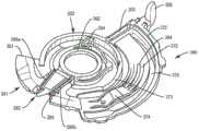
图12示出了盘形的底盘组件258,其包含中空枢转轴264、周边设置的外壳335和夹子325。中空枢转轴264可以装配在图11所示的外壳2b的轴68上。为了完成吸入器的致动机构,轴264适于容纳灌注构件。底盘266还设置有径向延伸部270,其与壳体2的内部相互作用以旋转地固定底盘266。底盘266包括引导构件271,其轴向地延伸并且在它们之间限定径向孔269。孔269允许刺棒(未示出)穿过底盘266朝向相应的托架12延伸。周边设置的外壳335与底盘266形成为一体,适于支撑转换机构的部件,在一些吸入器中是重要特征。底盘266还包括夹子325,其包含孔324,用于接收图9所示的槽分度机构。FIG. 12 shows a disc-shaped
与图9所示的底盘组件58不同的是,图12的底盘组件258包括与夹子325的孔324相邻设置的架子300。架子300限定孔326,其在一端通过支撑壁302界定,而在另一端通过凹入连接器304界定。Unlike the
在某些应用中,结合了架子元件的底盘可通过使槽分度机构过分挠性而使底盘结构变形。为了克服潜在变形,提供了附加支撑结构,如图13所示。In some applications, chassis incorporating shelf elements can deform the chassis structure by making the slot indexing mechanism too flexible. To overcome potential deformation, additional support structures are provided, as shown in Figure 13.
图13示出了盘形的底盘组件358的另一实施例,包含中空枢转轴364、周边设置的外壳435和夹子425。中空枢转轴364可以装配在图11所示的外壳2b的轴68上。为了完成吸入器的致动机构,轴364适于容纳灌注构件。底盘366还设置有径向延伸部370,其与壳体2的内部相互作用以旋转地固定底盘366。底盘366包括引导构件371,其轴向地延伸并且在它们之间限定径向孔369。孔369允许刺棒(未示出)穿过底盘366朝向相应的托架12延伸。周边设置的外壳435与底盘366形成为一体,适于支撑转换机构的部件,在一些吸入器中是重要特征。底盘366进一步包括夹子425,其包含孔424,用于接收图9所示的槽分度机构。FIG. 13 shows another embodiment of a
与图9所示的底盘组件58不同的是,图13的底盘组件358包括与夹子425的孔424相邻设置的架子400。架子400限定孔426,其在一端通过支撑壁402界定,而在另一端通过支柱支撑件312d界定。通常沿圆周设置的其他支柱312a、312b、312c和312e改善了底盘366的机械稳定性和放置在孔424中的槽分度机构。底盘366还可以包含多个径向设置的肋310a、310b和310c,这也意味着以增强底盘366的机械稳定性。还可以将位于夹子425和相对架子400附近的周边设置的低台阶306和高台阶307并入底盘366中,以改善模制过程。Unlike the
吸入器1的致动机构可以包括如图14和15所示的灌注构件的其他实施例。图14示出了灌注构件260。灌注构件260由以塑料模制的盘形板形成,具有中心枢转开口262,通过其而可旋转地支撑在例如底盘266的枢转轴264上。灌注构件260包括形成在灌注构件260上并通过底盘266的引导部件271可延伸穿过的细长凸轮开口279与灌注构件260的其余部分分开的细长凸轮构件272。细长凸轮构件272在圆周方向上延伸并且具有适于提供有限量的挠性的轮廓。中心凸轮表面274设置在凸轮构件272的两个相对侧的每个上。侧向凸轮表面273、275在灌注构件260的任一侧上沿着与细长凸轮构件272相对的细长凸轮开口279在圆周方向上延伸。灌注构件260包括在凸轮构件272的任一侧上的细长凸轮开口279,刺棒(未示出)的臂可延伸穿过该细长凸轮开口。如图14所示,凸轮表面274设置有一个或多个凹槽或通道284。为了提供附加稳定性,灌注构件260包括锥形连接器204,其接合侧向凸轮表面273和中心枢转开口262以及位于灌注杆208附近的升高的连接器205。The actuation mechanism of the inhaler 1 may comprise other embodiments of the irrigation member as shown in FIGS. 14 and 15 . FIG. 14 shows a
旋转灌注构件260在单个模制部件内结合了先前描述的许多功能元件。它包括灌注杆208、凸轮构件274、刺棒(未示出)和挠性悬臂叶片283,并且是用于为槽轮100分度的驱动构件。
驱动构件281设置有前部201,其包括依次布置的用于促进组装的切口;挠性悬臂叶片283,其可以分别在图12或13所示的底盘架子300或400上方和下方行进;以及后缘285。悬臂叶片283通过铰链挠曲挠性地附接到灌注构件260,从而允许其在向上和向下的方向上移动,并且在任一侧具有两个开口286a和286b。悬臂叶片283的结构的其他细节在图16中示出。图16的悬臂叶片283具有近端部分292、远端部分295和设置在远端部分295处的尖端294。悬臂叶片283包括从近端部分292延伸到远端部分295的纵向轴线L1和沿着横向轴线W1横向于纵向轴线L1延伸的挠性部分290。悬臂叶片283具有第一表面296和第二表面298。第一表面296和第二表面298均沿着纵向轴线L1延伸。第一表面296设置为与第二表面298相对,使得在灌注构件260和第一表面296之间形成第一间隙286a,并且在灌注构件260和第二表面298之间形成第二间隙286b。悬臂叶片283的主体可具有如图15和17所示的大致矩形或锥形主体形状。The
在图15中示出了致动机构的灌注构件的另一实施例。灌注构件360具有中心枢转开口362,例如通过其而可旋转地支撑在底盘366的枢转轴364上。灌注构件360可以由以塑料模制的盘形板形成。灌注构件360包括形成在灌注构件360上并通过底盘366的引导构件371可延伸穿过的细长凸轮开口379与灌注构件360的其余部分分开的细长凸轮构件372。细长凸轮构件372在圆周方向上延伸并且具有适于提供有限量的挠性的轮廓。中心凸轮表面374设置在凸轮构件372的两个相对侧的每个上。侧向凸轮表面373、375在灌注构件360的任一侧上沿着与细长凸轮构件372相对的细长凸轮开口379在圆周方向上延伸。灌注构件360包括在凸轮构件372的任一侧上的细长凸轮开口379,刺棒(未示出)的臂可延伸穿过该细长凸轮开口。如图15所示,中心凸轮表面374设置有一个或多个凹槽或通道384。为了提供额外稳定性并避免不希望的挠曲或扭曲,灌注构件360包括圆周肋200,其连接侧向凸轮表面373和驱动构件381的前部301。此外,为了提高灌注构件360的坚固性,前部301不包括如图14所示的实施例中的切口部分。另外,邻近灌注杆308并且将侧向凸轮表面373连接至中心枢转开口362的连接器已被取芯用于凹入连接器304和凹入锥形连接器305。这些连接器的取芯用于控制灌注构件的潜在变形。Another embodiment of the priming member of the actuation mechanism is shown in FIG. 15 . The
旋转灌注构件360在单个模制部件内结合了先前描述的许多功能元件。它包括灌注杆308、凸轮构件374、刺棒(未示出)和挠性锥形悬臂叶片383,并且是用于为槽轮100分度的驱动构件。挠性悬臂叶片383可以分别在图12或13所示的底盘架子300或400上方和下方移动,是前部301的一部分,其还包含依次布置的后缘385。悬臂叶片383通过铰链挠曲挠性地附接到灌注构件360,从而允许其在向上和向下方向上移动,并且在任一侧具有两个开口386a和386b。锥形悬臂叶片383的结构的其他细节在图17中示出。图17的悬臂叶片383具有近端部分392、远端部分395和设置在远端部分395处的尖端394。悬臂叶片383包括从近端部分392延伸到远端部分395的纵向轴线L2和沿着横向轴线W2横向于纵向轴线L2延伸的挠性部分390。锥形悬臂叶片383具有第一表面396和第二表面398。第一表面396和第二表面398均沿着纵向轴线L2延伸。第一表面396与第二表面398相对放置,从而在灌注构件360和第一表面396之间形成第一间隙386a,并且在灌注构件360和第二表面398之间形成第二间隙386b。为了优化与底盘架子的相互作用,尖端394包含成角度的倒角。
图12-17所示的包括底盘和灌注构件的致动机构的误用可形成如图18所示的误用区域。在误用区域中,致动步骤不能轻易地暂停。如果在打开袋之前返回了灌注杆,则灌注构件将不会到达底盘架子的末端,而是会返回到架子的顶部。该装置既不会分度也不会计数,并且计数器会暂时延迟,并在服用剂量后显示一个分度。然而,在下一致动时,将再次刺入同一个袋,不输送任何剂量,但是该装置将正常分度和计数,并且计数器现在可以正确表示所服用的剂量。如图12-17的实施例中所示的底盘和灌注构件的结构变化导致如图18所示的误用区域的显著减少或甚至潜在消除。尽管在一些实施例中,灌注杆可以在误用区域中行进三分之一,但在图12-17的实施例中,灌注杆在误用区域内行进小于约5%。结果,在这些实施例中,如图18所示,通过误用区域的力分布显著减小。在图12-17的实施例中,误用的影响不再关键,并且尽管计数器与所输送的剂量暂时不同步,但它会在下次使用时进行纠正。Misuse of the actuation mechanism including the chassis and priming member shown in FIGS. 12-17 can create a misuse area as shown in FIG. 18 . In the misuse zone, the actuation step cannot be easily suspended. If the priming rod is returned before the bag is opened, the priming member will not reach the end of the chassis shelf, but will return to the top of the shelf. The device neither scales nor counts, and the counter is temporarily delayed and shows a scale after a dose has been taken. However, on the next actuation, the same bag will be pierced again and no dose will be delivered, however the device will index and count normally and the counter will now correctly represent the dose taken. Structural changes to the chassis and perfusion members as shown in the embodiment of FIGS. 12-17 result in a significant reduction or even potential elimination of misused areas as shown in FIG. 18 . While in some embodiments the irrigation rod can travel a third of the way into the misuse area, in the embodiment of FIGS. 12-17 the irrigation rod travels less than about 5% into the misuse area. As a result, in these embodiments, as shown in FIG. 18, the force distribution through the misuse area is significantly reduced. In the embodiment of Figures 12-17, the effects of misuse are no longer critical, and although the counter is temporarily out of sync with the dose delivered, it will be corrected on next use.
在致动行程中,悬臂叶片在底盘上的架子上方越过,绕过槽分度机构,并且架子的末端与剂量打开同步。如果未将灌注杆大致推到行程末端,则悬臂叶片将返回到架子的顶部,而无需对盘或计数器进行分度,这将正确指示未服用剂量。在正确致动期间(直到行程末端),刚打开剂量后,悬臂叶片就从架子末端下落。当返回灌注杆时,悬臂叶片然后在底盘架子下方越过,其中它可以与槽分度机构接合,以将盘插入件推进到下一剂量并使计数器减小。During the actuation stroke, the cantilevered blade passes over the shelf on the chassis, around the slot indexing mechanism, and the end of the shelf is synchronized with the opening of the dose. If the priming rod is not pushed approximately to the end of the stroke, the cantilevered blade will return to the top of the shelf without indexing the disc or counter, which will correctly indicate an untaken dose. During correct actuation (until the end of stroke), the cantilevered blade drops from the end of the rack just after opening the dose. When returning to the priming rod, the cantilever blade then passes under the chassis shelf where it can engage the slot indexing mechanism to advance the disc insert to the next dose and decrement the counter.
图19示出了底盘410的实施例,其呈盘形联接到也为盘形的灌注构件412,底盘包含中空枢转轴401,灌注构件围绕开口403附接到枢转轴。灌注构件可以在输送剂量药物时围绕底盘在轴线A1上旋转,并且计数器将指示已输送剂量。提供了槽轮404并将其附接到底盘。槽轮还包括与钉轮408同轴的齿轮406,并且适于分别与联接部分和支撑件配合。FIG. 19 shows an embodiment of a
灌注构件结合了先前描述的许多功能元件。它包括灌注杆414、凸轮构件421、刺棒420和悬臂叶片422,并且是用于为槽轮分度的驱动构件。The perfusion member incorporates many of the functional elements previously described. It includes a
灌注构件包括构造成与吸入器的底盘接合的悬臂叶片,悬臂叶片422具有近端部分423、主体424和远端部分,该主体设置在悬臂叶片的近端部分和远端部分之间,并且悬臂叶片具有与悬臂叶片的近端部分一起延伸的挠性部分427,以允许悬臂叶片相对于底盘运动。悬臂叶片在朝向底盘的方向(例如向下方向)上成约5、10、15、20、25、30、35至约40度的角度。挠性部分是铰链挠曲,其允许悬臂叶片相对于底盘沿向上和向下方向移动。悬臂叶片允许均匀地输送药物并精确计数药物剂量。The irrigation member comprises a cantilevered blade configured to engage the chassis of the inhaler, the cantilevered
邻近悬臂叶片的是第一间隙428,其形成在灌注构件和悬臂叶片之间。该间隙尤其为悬臂叶片相对于底盘和/或灌注构件的竖直运动留出空间。Adjacent the cantilever vane is a
在所示的实施例中,将刺棒420安装在灌注构件上,并且将侧向凸轮表面416和418布置在灌注构件上,以为吸入器提供稳定性。In the illustrated embodiment, prod 420 is mounted on the irrigation member, and lateral cam surfaces 416 and 418 are disposed on the irrigation member to provide stability to the inhaler.
图20示出了底盘502的实施例,底盘502呈盘形联接至也为盘形的灌注元件500,底盘包含中空枢转轴506,并且灌注构件围绕开口504附接到枢转轴。灌注构件可以在输送药物剂量时围绕底盘旋转,并且计数器将指示已递送剂量。提供了槽轮并将其附接到底盘。FIG. 20 shows an embodiment of a
灌注构件结合了先前描述的许多功能元件。它包括灌注杆521和悬臂叶片512,并且是用于为槽轮分度的驱动构件。The perfusion member incorporates many of the functional elements previously described. It includes the
灌注构件包括构造成与吸入器的底盘接合的悬臂叶片512,悬臂叶片具有近端部分510、主体和远端部分514,该主体设置在悬臂叶片的近端部分和远端部分之间,悬臂叶片具有挠性部分508,其与悬臂叶片的近端部分一起延伸,以允许悬臂叶片相对于底盘运动。悬臂叶片示出为三角形,其在朝向底盘的方向(例如向下方向)上成约5、10、15、20、25、30、35至约40度的角度。挠性部分可以是铰链,其允许悬臂叶片相对于底盘沿向上和向下方向移动。悬臂叶片包括尖端516,其可以如图所示呈锥形和成角度。悬臂叶片允许药物的均匀输送和药物剂量的精确计数。The irrigation member includes a cantilevered
邻近悬臂叶片的是第一间隙520,第二间隙518形成在灌注构件和悬臂叶片之间。这些间隙尤其为悬臂叶片相对于底盘和/或灌注构件的竖直运动留出空间。将理解的是,挠性部分508可以由与灌注构件相同的材料制成。它可以设计成具有铰链,在一些实施例中是接头,以允许悬臂叶片相对于灌注构件和/或底盘竖直运动。第一间隙520和第二间隙518可以彼此平行或基本平行,并与悬臂叶片512的至少一部分纵向地延伸。在一些实施例中,悬臂叶片适于在致动吸入器时在底盘的一部分上方越过,而在分度吸入器时在底盘的一部分下方越过。Adjacent to the cantilever vane is a
图21示出了底盘600的实施例,底盘600呈盘形联接到也为盘形的灌注构件602,底盘包含中空枢转轴608,并且灌注构件围绕开口606附接到枢转轴。灌注构件可以在输送药物剂量时绕底盘旋转,并且计数器将指示已输送剂量。提供了槽轮并将其附接到底盘。FIG. 21 shows an embodiment of a
灌注构件结合了先前描述的许多功能元件。它包括灌注杆604和悬臂叶片,并且是为槽轮分度的驱动构件。The perfusion member incorporates many of the functional elements previously described. It includes a
灌注构件包括构造成与吸入器的底盘接合的悬臂叶片,该悬臂叶片具有近端部分616、成角度的主体620和远端部分610,该主体设置在悬臂叶片的近端部分和远端部分之间,悬臂叶片具有挠性部分,其与悬臂叶片的近端部分一起延伸,以允许悬臂叶片相对于底盘移动。悬臂叶片示出为矩形形状,并且具有升高部分618,其在远离底盘的方向(例如向上方向)上成约5、10、15、20、25、30、35至约40度的角度。挠性部分可以是铰链,其允许悬臂叶片相对于底盘沿向上和向下方向移动。悬臂叶片包括可以被倒角的尖端,如图所示。悬臂叶片允许药物的均匀输送和药物剂量的精确计数。The irrigation member comprises a cantilevered blade configured to engage the chassis of the inhaler, the cantilevered blade having a
邻近悬臂叶片的是第一间隙612,第二间隙614形成在灌注构件和悬臂叶片之间。这些间隙尤其为悬臂叶片相对于底盘和/或灌注构件的竖直运动留出空间。将理解的是,挠性部分可以由与灌注构件相同的材料制成,并且相对于悬臂叶片的其余部分具有减小的厚度或增加的厚度,以用作铰链来允许悬臂叶片的其余部分移动。它可以设计成具有铰链,在一些实施例中是接头,以允许悬臂叶片相对于灌注构件和/或底盘竖直运动。第一间隙612和第二间隙614可彼此平行或基本平行,并与悬臂叶片的至少一部分纵向地延伸。在一些实施例中,悬臂叶片适于在致动吸入器时在底盘的一部分上方越过,而在分度吸入器时在底盘的一部分下方越过。Adjacent to the cantilever vane is a
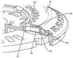
图22-28示出了底盘700的实施例,该底盘700呈盘形联接至图15和17的灌注构件360。底盘700包括先前描述的许多功能元件。底盘700还包括具有前缘704和后缘710的底盘架子702。前缘704包括上倾斜的倒角706和下倾斜的倒角708,如图23所示。成角度的斜面706、708构造成与悬臂尖端394接合,使得悬臂尖端394在致动或刺入行程期间(图23和24)在底盘架子702上方越过,而在分度或计数行程期间(图25-28)在底盘架子702下方越过。然而,驱动构件381的相邻部分可以在底盘架子702下方越过。应当理解,悬臂尖端394在底盘架子702上方和下方的运动允许悬臂叶片383与计数器更好地相互作用。例如,如果灌注杆308向后移动,它将不会与计数器接合,直到执行启动行程。因此,减少了错误计数的机会,或者消除了错误计数剂量。22-28 illustrate an embodiment of a
上倾斜的倒角706成一定角度以与悬臂尖端394配合并将悬臂尖端394向上并在底盘架子702上方引导。下倾斜的倒角708成一定角度以与驱动构件381的倾斜端部387配合并在底盘架子702下方引导悬臂尖端394。在一些实施例中,成角度的倒角706、708和/或驱动构件381的倾斜端部387可以相对于平面底盘架子成约5、6、7、8、9、10、11、12、13、14、15、16、17、18、19、20、21、22、23、24、25、26、27、28、29、30、31、32、33、34、35、36、37、38、39至约40度的角度。Up-sloped
如上所述,为了优化与底盘架子的相互作用,悬臂尖端394包含成角度的倒角,其可以相对于平面底盘架子成约5、6、7、8、9、10、11、12、13、14、15、16、17、18、19、20、21、22、23、24、25、26、27、28、29、30、31、32、33、34、35、36、37、38、39至约40度的角度。悬臂尖端394也成一定角度以优化与上倾斜的倒角706的相互作用。As mentioned above, to optimize the interaction with the chassis frame, the
悬臂叶片383和驱动构件381都在致动时在底盘架子702下方越过,使得底盘架子702的后缘710仅具有一个面向下的倒角712(图25),并且悬臂尖端394的表面成一定角度以与倒角712相互作用。倒角712也构造成与灌注构件360的后缘385接合。Both the
对于本领域技术人员将显而易见的是,在不脱离本文教导的精神或范围的情况下,可以对本文描述的各个实施例进行各种修改和变化。因此,意图是各个实施例覆盖在本教导的范围内的各个实施例的其他修改和变化。It will be apparent to those skilled in the art that various modifications and changes can be made in the various embodiments described herein without departing from the spirit or scope of the teachings herein. Thus, it is intended that the various embodiments cover other modifications and variations of the various embodiments that fall within the scope of the present teachings.
Claims (29)
Translated fromChineseApplications Claiming Priority (1)
| Application Number | Priority Date | Filing Date | Title |
|---|---|---|---|
| PCT/US2018/041424WO2020013809A1 (en) | 2018-07-10 | 2018-07-10 | Device counter |
Publications (2)
| Publication Number | Publication Date |
|---|---|
| CN113015547A CN113015547A (en) | 2021-06-22 |
| CN113015547Btrue CN113015547B (en) | 2023-04-07 |
Family
ID=69141987
Family Applications (1)
| Application Number | Title | Priority Date | Filing Date |
|---|---|---|---|
| CN201880097160.9AActiveCN113015547B (en) | 2018-07-10 | 2018-07-10 | Device counter |
Country Status (6)
| Country | Link |
|---|---|
| US (1) | US20210283347A1 (en) |
| EP (1) | EP3833412A4 (en) |
| CN (1) | CN113015547B (en) |
| AU (1) | AU2018431731B2 (en) |
| CA (1) | CA3105978A1 (en) |
| WO (1) | WO2020013809A1 (en) |
Citations (4)
| Publication number | Priority date | Publication date | Assignee | Title |
|---|---|---|---|---|
| CN101827626A (en)* | 2008-06-13 | 2010-09-08 | 曼金德公司 | Dry powder inhaler and system for drug delivery |
| CN102438684A (en)* | 2009-01-30 | 2012-05-02 | 维克多瑞传送设备有限公司 | Inhaler |
| WO2013175177A1 (en)* | 2012-05-25 | 2013-11-28 | Vectura Delivery Devices Limited | Inhaler |
| EP3042681A1 (en)* | 2013-09-02 | 2016-07-13 | Daiwa Can Company | Inhaler |
Family Cites Families (9)
| Publication number | Priority date | Publication date | Assignee | Title |
|---|---|---|---|---|
| US6082358A (en)* | 1998-05-05 | 2000-07-04 | 1263152 Ontario Inc. | Indicating device for aerosol container |
| GB9920839D0 (en) | 1999-09-04 | 1999-11-10 | Innovata Biomed Ltd | Inhaler |
| GB0315509D0 (en)* | 2003-07-02 | 2003-08-06 | Meridica Ltd | Dispensing device |
| DE102006045788A1 (en)* | 2006-09-26 | 2008-03-27 | Alfred Von Schuckmann | Dispenser for powdery masses |
| CA2732826C (en)* | 2008-09-26 | 2017-08-22 | Oriel Therapeutics, Inc. | Inhaler mechanisms with radially biased piercers and related methods |
| SI2346556T1 (en)* | 2008-09-26 | 2015-02-27 | Oriel Therapeutics, Inc. | Dry powder inhalers with dual piercing members and related devices and methods |
| WO2010039200A2 (en) | 2008-09-30 | 2010-04-08 | Oriel Therapeutics, Inc. | Dry powder inhalers with endless strips and cooperating piercers and related methods |
| JP5759182B2 (en)* | 2010-01-20 | 2015-08-05 | ファイザー・リミテッドPfizer Limited | Device for dispensing multiple unit doses of dry powder and an inhaler comprising such a device |
| US10357622B2 (en)* | 2013-12-23 | 2019-07-23 | Glenmark Pharmaceuticals Limited | Dry powder inhaler |
- 2018
- 2018-07-10CNCN201880097160.9Apatent/CN113015547B/enactiveActive
- 2018-07-10AUAU2018431731Apatent/AU2018431731B2/enactiveActive
- 2018-07-10CACA3105978Apatent/CA3105978A1/enactivePending
- 2018-07-10WOPCT/US2018/041424patent/WO2020013809A1/ennot_activeCeased
- 2018-07-10EPEP18925742.1Apatent/EP3833412A4/enactivePending
- 2018-07-10USUS17/259,047patent/US20210283347A1/enactivePending
Patent Citations (4)
| Publication number | Priority date | Publication date | Assignee | Title |
|---|---|---|---|---|
| CN101827626A (en)* | 2008-06-13 | 2010-09-08 | 曼金德公司 | Dry powder inhaler and system for drug delivery |
| CN102438684A (en)* | 2009-01-30 | 2012-05-02 | 维克多瑞传送设备有限公司 | Inhaler |
| WO2013175177A1 (en)* | 2012-05-25 | 2013-11-28 | Vectura Delivery Devices Limited | Inhaler |
| EP3042681A1 (en)* | 2013-09-02 | 2016-07-13 | Daiwa Can Company | Inhaler |
Also Published As
| Publication number | Publication date |
|---|---|
| AU2018431731A1 (en) | 2021-01-28 |
| AU2018431731B2 (en) | 2025-04-10 |
| US20210283347A1 (en) | 2021-09-16 |
| CA3105978A1 (en) | 2020-01-16 |
| WO2020013809A1 (en) | 2020-01-16 |
| EP3833412A1 (en) | 2021-06-16 |
| CN113015547A (en) | 2021-06-22 |
| EP3833412A4 (en) | 2022-06-15 |
Similar Documents
| Publication | Publication Date | Title |
|---|---|---|
| US20210369991A1 (en) | Dispensing device | |
| JP5651233B2 (en) | Simple capsule-based inhaler | |
| KR20080103060A (en) | Inhalers for Powdered Materials | |
| CN113015547B (en) | Device counter | |
| HK40006586B (en) | Dispensing device |
Legal Events
| Date | Code | Title | Description |
|---|---|---|---|
| PB01 | Publication | ||
| PB01 | Publication | ||
| SE01 | Entry into force of request for substantive examination | ||
| SE01 | Entry into force of request for substantive examination | ||
| GR01 | Patent grant | ||
| GR01 | Patent grant |