CN113011634A - Intelligent network connection ramp merging method based on distributed optimal control - Google Patents
Intelligent network connection ramp merging method based on distributed optimal controlDownload PDFInfo
- Publication number
- CN113011634A CN113011634ACN202110182147.7ACN202110182147ACN113011634ACN 113011634 ACN113011634 ACN 113011634ACN 202110182147 ACN202110182147 ACN 202110182147ACN 113011634 ACN113011634 ACN 113011634A
- Authority
- CN
- China
- Prior art keywords
- vehicle
- merging
- constraints
- time
- vehicles
- Prior art date
- Legal status (The legal status is an assumption and is not a legal conclusion. Google has not performed a legal analysis and makes no representation as to the accuracy of the status listed.)
- Granted
Links
Images


Classifications
- G—PHYSICS
- G06—COMPUTING OR CALCULATING; COUNTING
- G06Q—INFORMATION AND COMMUNICATION TECHNOLOGY [ICT] SPECIALLY ADAPTED FOR ADMINISTRATIVE, COMMERCIAL, FINANCIAL, MANAGERIAL OR SUPERVISORY PURPOSES; SYSTEMS OR METHODS SPECIALLY ADAPTED FOR ADMINISTRATIVE, COMMERCIAL, FINANCIAL, MANAGERIAL OR SUPERVISORY PURPOSES, NOT OTHERWISE PROVIDED FOR
- G06Q10/00—Administration; Management
- G06Q10/04—Forecasting or optimisation specially adapted for administrative or management purposes, e.g. linear programming or "cutting stock problem"
- G06Q10/047—Optimisation of routes or paths, e.g. travelling salesman problem
- G—PHYSICS
- G06—COMPUTING OR CALCULATING; COUNTING
- G06Q—INFORMATION AND COMMUNICATION TECHNOLOGY [ICT] SPECIALLY ADAPTED FOR ADMINISTRATIVE, COMMERCIAL, FINANCIAL, MANAGERIAL OR SUPERVISORY PURPOSES; SYSTEMS OR METHODS SPECIALLY ADAPTED FOR ADMINISTRATIVE, COMMERCIAL, FINANCIAL, MANAGERIAL OR SUPERVISORY PURPOSES, NOT OTHERWISE PROVIDED FOR
- G06Q50/00—Information and communication technology [ICT] specially adapted for implementation of business processes of specific business sectors, e.g. utilities or tourism
- G06Q50/10—Services
- G06Q50/26—Government or public services
- G—PHYSICS
- G16—INFORMATION AND COMMUNICATION TECHNOLOGY [ICT] SPECIALLY ADAPTED FOR SPECIFIC APPLICATION FIELDS
- G16Y—INFORMATION AND COMMUNICATION TECHNOLOGY SPECIALLY ADAPTED FOR THE INTERNET OF THINGS [IoT]
- G16Y10/00—Economic sectors
- G16Y10/40—Transportation
- G—PHYSICS
- G16—INFORMATION AND COMMUNICATION TECHNOLOGY [ICT] SPECIALLY ADAPTED FOR SPECIFIC APPLICATION FIELDS
- G16Y—INFORMATION AND COMMUNICATION TECHNOLOGY SPECIALLY ADAPTED FOR THE INTERNET OF THINGS [IoT]
- G16Y20/00—Information sensed or collected by the things
- G16Y20/10—Information sensed or collected by the things relating to the environment, e.g. temperature; relating to location
- G—PHYSICS
- G16—INFORMATION AND COMMUNICATION TECHNOLOGY [ICT] SPECIALLY ADAPTED FOR SPECIFIC APPLICATION FIELDS
- G16Y—INFORMATION AND COMMUNICATION TECHNOLOGY SPECIALLY ADAPTED FOR THE INTERNET OF THINGS [IoT]
- G16Y20/00—Information sensed or collected by the things
- G16Y20/20—Information sensed or collected by the things relating to the thing itself
- G—PHYSICS
- G16—INFORMATION AND COMMUNICATION TECHNOLOGY [ICT] SPECIALLY ADAPTED FOR SPECIFIC APPLICATION FIELDS
- G16Y—INFORMATION AND COMMUNICATION TECHNOLOGY SPECIALLY ADAPTED FOR THE INTERNET OF THINGS [IoT]
- G16Y40/00—IoT characterised by the purpose of the information processing
- G16Y40/30—Control
- G16Y40/35—Management of things, i.e. controlling in accordance with a policy or in order to achieve specified objectives
- Y—GENERAL TAGGING OF NEW TECHNOLOGICAL DEVELOPMENTS; GENERAL TAGGING OF CROSS-SECTIONAL TECHNOLOGIES SPANNING OVER SEVERAL SECTIONS OF THE IPC; TECHNICAL SUBJECTS COVERED BY FORMER USPC CROSS-REFERENCE ART COLLECTIONS [XRACs] AND DIGESTS
- Y02—TECHNOLOGIES OR APPLICATIONS FOR MITIGATION OR ADAPTATION AGAINST CLIMATE CHANGE
- Y02T—CLIMATE CHANGE MITIGATION TECHNOLOGIES RELATED TO TRANSPORTATION
- Y02T10/00—Road transport of goods or passengers
- Y02T10/10—Internal combustion engine [ICE] based vehicles
- Y02T10/40—Engine management systems
Landscapes
- Engineering & Computer Science (AREA)
- Business, Economics & Management (AREA)
- Human Resources & Organizations (AREA)
- Economics (AREA)
- Computing Systems (AREA)
- General Business, Economics & Management (AREA)
- Tourism & Hospitality (AREA)
- Development Economics (AREA)
- Strategic Management (AREA)
- Physics & Mathematics (AREA)
- Health & Medical Sciences (AREA)
- Operations Research (AREA)
- Marketing (AREA)
- General Health & Medical Sciences (AREA)
- General Physics & Mathematics (AREA)
- Theoretical Computer Science (AREA)
- Educational Administration (AREA)
- Quality & Reliability (AREA)
- Entrepreneurship & Innovation (AREA)
- Primary Health Care (AREA)
- Accounting & Taxation (AREA)
- Game Theory and Decision Science (AREA)
- Environmental & Geological Engineering (AREA)
- Toxicology (AREA)
- Traffic Control Systems (AREA)
Abstract
Translated fromChinese
Description
Translated fromChinese技术领域technical field
本发明涉及智能网联车、最优控制领域、自动驾驶领域,具体发明一种基于最优控制的分布式智能网联车匝道合并方法。在车联网技术和5G的背景下,针对智能网联车(CAVs)建构一个新的实时控制框架,以分布式控制的方式,根据车辆的合并约束、安全约束和速度约束,通过最优控制得到智能网联车的最优轨迹,调节车辆的驾驶速度,最小化各智能网联车的通行时间和能耗,提高路网通行效率。The invention relates to the fields of intelligent networked vehicles, optimal control and automatic driving, and in particular invents a method for merging ramps of distributed intelligent networked vehicles based on optimal control. In the context of Internet of Vehicles technology and 5G, a new real-time control framework is constructed for intelligent networked vehicles (CAVs). The optimal trajectory of the ICV can adjust the driving speed of the vehicle, minimize the travel time and energy consumption of each ICV, and improve the traffic efficiency of the road network.
背景技术Background technique
随着经济的发展,汽车保有量不断上升,城市地区不断增加的车辆已经使现有基础设施饱和,造成交通系统拥堵。城市交叉口、道路合并、减速区域以及周围驾驶员的干扰是造成安全、拥堵和能源消耗的主要来源,同时也是许多司机的压力来源。城市快速路中的匝道合并区域集合了上述的描述的干扰因素,是引起交通事故和拥堵的重要的场景,甚至严重影响燃料消耗和旅行时间。因此,交织区的交通控制,特别是城市快速路入口匝道的交通控制是交通系统中最具挑战性的问题之一。With economic development, car ownership continues to rise, and the increasing number of vehicles in urban areas has saturated existing infrastructure and caused traffic system congestion. Urban intersections, road merging, deceleration zones, and disturbance from surrounding drivers are major sources of safety, congestion and energy consumption, as well as a source of stress for many drivers. Ramp merging areas in urban expressways integrate the disturbance factors described above, and are important scenarios that cause traffic accidents and congestion, and even seriously affect fuel consumption and travel time. Therefore, traffic control in weaving areas, especially on urban expressway on-ramps, is one of the most challenging problems in the transportation system.
交通系统技术的进步和智能网联车的出现,使得计算延迟大幅减小,控制框架能快速处理大量的数据,并提供实时控制动作,帮助司机做出准确和快速决策以更好地帮助用户监控运输网络状况,极大地改善交通网络的性能,使车联网的通信效率大幅提高。智能网联车采用不同的通信技术与驾驶员、道路上的其他车辆通过“车辆到车辆”(V2V),路边基础设施(V2I)和“云”进行通信,充分利用联网车辆和自动化车辆的优势,不仅可以使用内部传感器与其他车辆隔离运行,而且可以与附近的车辆和基础设施进行通信,实现车车/车路信息交互,每一辆车可以按照预设的交通规则或指令通过匝道入口,以协作方式做出决策,优化能源消耗和交通效率,并最终减少空气污染、拥堵和事故,因此智能网联汽车对匝道路口通行效率的研究十分必要。The advancement of transportation system technology and the emergence of intelligent networked vehicles have greatly reduced computing delays, and the control framework can quickly process large amounts of data and provide real-time control actions to help drivers make accurate and fast decisions to better help users monitor The condition of the transportation network greatly improves the performance of the transportation network and greatly improves the communication efficiency of the Internet of Vehicles. Connected vehicles use different communication technologies to communicate with the driver, other vehicles on the road through "vehicle-to-vehicle" (V2V), roadside infrastructure (V2I) and "cloud" to take full advantage of the capabilities of connected and automated vehicles. Advantages, not only can use internal sensors to operate in isolation from other vehicles, but also communicate with nearby vehicles and infrastructure to realize vehicle/vehicle road information interaction, and each vehicle can pass the ramp entrance according to preset traffic rules or instructions , make decisions in a collaborative manner, optimize energy consumption and traffic efficiency, and ultimately reduce air pollution, congestion, and accidents, so the research on the efficiency of on-ramp crossings by ICVs is necessary.
为驾驶员提供高速公路合并辅助引导以避免拥堵和碰撞的研究有很大的意义。因此在车辆控制方面研究人员做了大量的研究,重点是为驾驶员提供避免拥堵和碰撞的指导。Weng等人使用分类回归树(CART)方法对实施合并期间工作区域合并区域的车辆合并行为进行建模。Chen等人提出了一种将交通预测、驾驶员行为分析和交通信号优化相结合的系统,引导匝道车辆顺利进入主干道。当两条道路上的车辆以相同速度向同一方向行驶,Dresner和Stone提出使用预约方案来控制单个交织区的两条道路。有些方法侧重于在交织区协调车辆以提高出行时间,在之前的工作中,几种分布式合并控制机制已经被提出,智能网联车在不同道路上的行驶轨迹通过建立分散最优控制框架进行协调。基于模型预测控制,Zhang和Cassandras提出了一种分布式优化方法,该方法允许每个智能网联车根据周围其他车辆的情况、道路的速度、加/减速度的最大值在局部区域内生成运动曲线。Colombo和Del Vecchio构造了保证避免横向碰撞的控制输入的不变集。无约束问题的解决方案也在特拉华大学的按比例缩小的智能城市实验中,使用10辆机器人汽车在一个合并的道路场景得到验证。但在分布式控制中,所有的计算都针对单一车辆,并且只与受其影响的少数车辆共享。并且,这些算法只关注单一交织区,而没有考虑到涉及多个入口匝道的合并区。因此,多入口匝道的合并区求解仍然是一个尚未解决的问题。There are great implications for the study of providing drivers with highway merging assist guidance to avoid congestion and collisions. Therefore, researchers have done a lot of research in vehicle control, focusing on providing drivers with guidance to avoid congestion and collisions. Weng et al. used a classification regression tree (CART) approach to model vehicle merging behavior in work area merging areas during implementation of merging. Chen et al. proposed a system that combines traffic prediction, driver behavior analysis, and traffic signal optimization to guide on-ramp vehicles smoothly into arterial roads. Dresner and Stone propose to use a reservation scheme to control two roads in a single weaving area when vehicles on two roads are traveling in the same direction at the same speed. Some methods focus on coordinating vehicles in the weaving area to improve travel time. In previous work, several distributed combined control mechanisms have been proposed. The driving trajectories of ICVs on different roads are controlled by establishing a decentralized optimal control framework. coordination. Based on model predictive control, Zhang and Cassandras proposed a distributed optimization method that allows each ICV to generate motion in a local area based on the conditions of other vehicles around it, the speed of the road, and the maximum acceleration/deceleration curve. Colombo and Del Vecchio construct an invariant set of control inputs guaranteed to avoid lateral collisions. The solution to the unconstrained problem was also validated in a scaled-down smart city experiment at the University of Delaware using 10 robotic cars in a combined road scene. But in distributed control, all computations are directed to a single vehicle and shared only with the few vehicles affected by it. Also, these algorithms focus only on a single interleaving area and do not take into account the merging area involving multiple on-ramps. Therefore, the merging zone solution for multiple on-ramps remains an open problem.
基于上述问题,本发明做出了以下改进:首先采用了分布式最优控制的算法,根据智能网联车(CAVs)可以实时控制反馈的特性,搭建了一种实时控制框架,通过协调可能发生的冲突来缓解交通问题。其次,考虑主线和辅路车道中车辆的统筹问题,我们提出虚拟映射的概念,将不同车道的车辆映射到同一车道上,使车辆提前感知交织区交通场景,保证车辆在交织区车辆安全、速度、合并等约束条件得到满足。最后,将单个汇入口匝道轨迹模型扩展到多个入口匝道合并路段进行协调控制,提高交通通行效率和安全。Based on the above problems, the present invention makes the following improvements: first, a distributed optimal control algorithm is adopted, and a real-time control framework is built according to the characteristics of intelligent networked vehicles (CAVs) that can control feedback in real time. conflict to alleviate traffic problems. Secondly, considering the overall planning of vehicles in the main and auxiliary road lanes, we propose the concept of virtual mapping, which maps vehicles in different lanes to the same lane, so that vehicles can perceive the traffic scene in the weaving area in advance, and ensure the safety, speed, and safety of vehicles in the weaving area. Constraints such as merging are satisfied. Finally, a single on-ramp trajectory model is extended to multiple on-ramp merged sections for coordinated control to improve traffic efficiency and safety.
发明内容SUMMARY OF THE INVENTION
本发明提出了一种基于分布式最优控制的智能网联车匝道合并方法。在车联网环境下,建构一个新的实时控制框架,通过最优控制方法,解决从不同道路到匝道合并点的最优控制问题,得到车辆的最优轨迹,随后扩展到多匝道合并段的车辆协调。以实现最大化交织区路段的路网的通行效率和最小化能耗。发明内容共分为五部分进行说明,第一步:在车联网环境下,根据车辆动力学模型为每辆智能车建立模型和约束;第二步:采用虚拟映射的方法将不同车道智能车映射到同一车道;第三步:建立智能车驾驶的目标函数和分布式框架;第四步:实现单入口匝道合并区智能车协调,对车辆从主线或辅路进入控制区,到达合流区过程中的不同情况分别进行计算,获得车辆的最优轨迹;第五步:基于单路口最优控制,实现多个入匝道合并路段的协调。The invention proposes a ramp merging method for intelligent networked vehicles based on distributed optimal control. In the Internet of Vehicles environment, a new real-time control framework is constructed to solve the optimal control problem from different roads to the merging point of the ramp through the optimal control method, obtain the optimal trajectory of the vehicle, and then extend it to vehicles in the merging section of multiple ramps coordination. In order to maximize the traffic efficiency and minimize the energy consumption of the road network in the interweaving area. The content of the invention is divided into five parts for description. The first step is to establish a model and constraints for each smart car according to the vehicle dynamics model in the Internet of Vehicles environment; the second step: use the virtual mapping method to map the smart cars in different lanes. To the same lane; Step 3: Establish the objective function and distributed framework for smart car driving; Step 4: Realize the coordination of smart cars in the merging area of a single on-ramp. Different situations are calculated separately to obtain the optimal trajectory of the vehicle; the fifth step: based on the optimal control of a single intersection, realize the coordination of multiple on-ramp merged sections.
基于上述分析,一种基于分布式最优控制的智能网联车匝道合并方法,具体实现步骤如下:Based on the above analysis, an intelligent networked vehicle ramp merging method based on distributed optimal control, the specific implementation steps are as follows:
步骤1、建立智能车模型和约束
通过自身的无线设备,智能车可以接入车联网中,并与相邻智能车或路侧设备进行信息传递和共享,获取计算自身最优轨迹的相关信息。车联网环境下的车辆根据车辆动力学模型我们为每辆智能车设置以下形式:Through its own wireless devices, smart cars can connect to the Internet of Vehicles, and transmit and share information with adjacent smart cars or roadside devices to obtain relevant information for calculating their own optimal trajectory. Vehicles in the Internet of Vehicles Environment According to the vehicle dynamics model, we set the following forms for each smart car:

其中xi表示车辆i在时刻t的位置,vi(t)和ui(t)分别表示车辆i在时刻t的速度和加速度(控制输入)。where xi represents the position of vehicle i at time t, and vi (t) andui( t) represent the speed and acceleration (control input) of vehicle i at time t, respectively.
为保证控制区内车辆的安全,现给出以下约束条件:In order to ensure the safety of vehicles in the control area, the following constraints are given:
约束1:为避免同一物理车道上CAV与前一车辆CAV在控制区发生追尾碰撞,我们提出CAV序列的安全约束:Constraint 1: To avoid a rear-end collision between a CAV and the preceding vehicle CAV in the control area on the same physical lane, we propose a safety constraint for the CAV sequence:

其中xip(t)表示车辆ip在时刻t的位置,xi(t)表示车辆i在时刻t的位置,


约束2:CAV在合并区域内不同车道的合并需要保持足够的安全距离,即:Constraint 2: The merging of different lanes of CAVs in the merging area needs to maintain a sufficient safety distance, namely:

其中


约束3:为保证车辆的控制输入和速度在安全范围内,给定以下条件:Constraint 3: To ensure that the control input and speed of the vehicle are within a safe range, the following conditions are given:


其中vmin和vm睯x分别表示对车辆设置的最小速度和最大速度,umin和umax分别表示对车辆设置的最小速度和最大速度,

步骤2、虚拟映射不同车道的智能车
城市快速路中,车辆可以从主线和辅路进入控制区进行合并。基于步骤1中约束,智能车在合并过程中可能会违反约束,甚至发生拥堵。为了使合并区域的通行效率更高,我们根据已知的车辆信息计算每辆车到达合并区域的时间,根据到达时间顺序对控制区内所有车辆进行排序,确定实际遵循的前车。为了实现不同车道上队列的整体规划,采用虚拟映射的方法将辅路车辆映射到主路,智能车根据到达合并区域的时间进行排序后,形成相应的虚拟车辆。可以看出,控制区内智能车跟随的前车可能是相同道路上的车辆,也可能是不同道路上的虚拟前车。In the urban expressway, vehicles can enter the control area from the main line and the auxiliary road for merging. Based on the constraints in
步骤3、建立智能车驾驶的目标函数和分布式框架Step 3. Establish the objective function and distributed framework for smart car driving
我们的目标是确定一个能使旅行时间和能量消耗最小的目标函数。此外,每个智能车必须符合步骤1中约束。在上述要求的基础上,我们构造了每个智能车的最优控制问题,其中:Our goal is to determine an objective function that minimizes travel time and energy consumption. In addition, each smart car must meet the constraints in

其中β是权重系数。针对给定的目标函数,构造具有状态约束、控制约束和安全约束的哈密顿函数:where β is the weight coefficient. For a given objective function, construct a Hamiltonian function with state constraints, control constraints, and security constraints:

其中


步骤4、实现智能车在单入口匝道合并区的协调
单入口匝道的合并区一般由一条辅路和一条主线组成。智能车可以从主线或辅路进入控制区,到达合流区。假设智能车进入控制区时处于不受约束状态。进入控制区域后,车辆的驾驶行为可能与前车在同一道路上的安全约束或前车在不同车道上的合并约束有关。如果智能车不受约束,它可以沿原轨迹运动。否则,就需要计算新的轨迹。下面为单入口匝道合流段下智能车的行驶模式:The merging area of a single on-ramp generally consists of a side road and a main line. The smart car can enter the control area from the main line or the auxiliary road and reach the merging area. It is assumed that the smart car is in an unconstrained state when it enters the control area. After entering the control area, the driving behavior of the vehicle may be related to the safety restraint of the preceding vehicle on the same road or the merging restraint of the preceding vehicle on different lanes. If the smart car is not constrained, it can move along the original trajectory. Otherwise, a new trajectory needs to be calculated. The following is the driving mode of the smart car in the merging section of the single on-ramp:
(1)无约束模式(控制、状态、安全约束未激活)(1) Unconstrained mode (control, state, safety constraints are not activated)
如果智能车满足步骤1中的三个约束,那么安全、状态和控制条件约束处于未激活状态,即拉格朗日乘子
ui+λiv=0ui +λiv =0
由欧拉-拉格朗日方程得:From the Euler-Lagrange equation we get:


由上式可得


其中


其中,


(2)安全模式(安全约束激活)(2) Safe mode (safety restraint activated)
当前后车辆在同一车道,计算出无约束行驶轨迹后,需要立即检查后车轨迹是否满足控制区域内的安全约束。如果在某个时刻t1车辆没有满足安全约束,为了避免车辆间冲突,需要重新规划一个满足约束的车辆轨迹。在这种情况下
ui+λiv=0ui +λiv =0
得到欧拉-拉格朗日方程:Get the Euler-Lagrange equation:


根据欧拉-拉格朗日方程得到以下最优解:According to the Euler-Lagrange equation, the following optimal solutions are obtained:


其中,gi,hi,pi和qi均为积分常数,假设安全约束在时刻
Ni(xi(t1),(vi(t1))=xi(t1)+φ·vi(t1)-xip(t1)=0Ni (xi (t1 ),(vi (t1 ))=xi( t1 )+φ·vi( t1 )-xip (t1 )=0
xi(t1)表示车辆i在时刻t1的位置,xip(t1)表示车辆ip在时刻t1的位置,vi(t1)表示车辆i在时刻t1的速度。


π为常数拉格朗日乘子,vip(t1)表示车辆ip在时刻t1的速度,上式表明在整个控制区域中的状态变量
(3)合并模式(安全合并约束激活)(3) Merge mode (safe merge constraint activation)
当前后车辆不在同一车道时,智能车需要在合并点满足安全约束。如果在合并点满足安全约束,智能车将遵循原轨迹。如果没有,我们重新计算合并约束下的曲线:When the front and rear vehicles are not in the same lane, the smart car needs to meet the safety constraints at the merging point. If the safety constraints are met at the merge point, the smart car will follow the original trajectory. If not, we recompute the curve under the merge constraint:

其中,


我们可以得到与(2)相同形式的解。对于任何时间
步骤5、多入口匝道合并路段的协调
基于单个入口匝道的合并情况,我们考虑了合并区段的一般情况。例如车辆可能在多个合并区与不同车辆产生冲突,在这种情况下,可以通过使用内点约束、在合并区域上设置限制条件来实现多个入口匝道合并区段的协调。Based on the merging of a single on-ramp, we consider the general case of merging segments. For example, vehicles may collide with different vehicles in multiple merging zones, in which case the coordination of multiple on-ramp merging segments can be achieved by using interior point constraints and placing constraints on the merging zones.
(1)无约束模式和单一约束激活:(1) Unconstrained mode and single constraint activation:
在多入口匝道合并路段的情况下,当CAV i服从安全约束、合并约束、控制和状态约束或违反其中一个约束情况下,车辆的驾驶模式与步骤4完全相同。In the case of multiple on-ramp merging segments, when CAV i obeys safety constraints, merging constraints, control and state constraints or violates one of the constraints, the vehicle's driving mode is exactly the same as in
(2)安全合并模式:(2) Safe merge mode:
假设CAV i从主路进入控制区,通过合并区域#1和#2,然后离开控制区。当车辆i,j和车辆i和i-1在前后不同合并段违反合并约束,则通过在前端合并区设置内部约束条件,使i和j满足安全合并约束。通过内部边界条件


其中,


根据两条曲线的条件,我们可以得到CAV i的相关信息例如:初速度


其中ai,bi,ci,gi,hi和qi为积分常数,


(3)安全和合并安全模式(3) Security and combined security mode
在通过上述两个合并区域的过程中,如果CAV i跟随的车辆是在后端合并区域的虚拟车辆,那么在行驶过程中,CAV i在物理道路上违反了安全约束,在违反安全约束的地方设置内点约束条件,重新计算满足所有约束条件的最优轨迹。计算条件与步骤5中(2)相同。In the process of passing through the above two merging areas, if the vehicle followed by CAV i is a virtual vehicle in the rear-end merging area, then during the driving process, CAV i violates the safety constraints on the physical road, and at the places where the safety constraints are violated Set interior point constraints and recalculate the optimal trajectory that satisfies all constraints. The calculation conditions are the same as (2) in
技术优势Technical advantages
本发明在智能网联车的背景下提出了一种能够准确、快速计算车辆在快速路合并路段行驶轨迹的方法。针对智能网联车建构一个新的实时控制框架,以分布式控制的方式,根据车辆的不同约束,通过最优控制得到智能网联车的最优轨迹。与传统方法相比,该方法以分布式的方式,根据每辆车的不同冲突进行控制,优化方向更为精准;提出了最优控制的优化方法,减小了轨迹的计算时间,增大了轨迹计算的准确程度;并且通过内点约束条件,将单个合并区拓展到多个合并区,实现了多合并区的联合合并,提高了路网的通行效率。The present invention proposes a method that can accurately and quickly calculate the travel trajectory of a vehicle on a merging section of an expressway in the context of an intelligent networked vehicle. A new real-time control framework is constructed for ICVs. In a distributed control manner, the optimal trajectory of ICVs can be obtained through optimal control according to different constraints of vehicles. Compared with the traditional method, this method controls according to the different conflicts of each vehicle in a distributed manner, and the optimization direction is more accurate; an optimization method for optimal control is proposed, which reduces the calculation time of the trajectory and increases the The accuracy of trajectory calculation; and through the interior point constraints, a single merged area is extended to multiple merged areas, the joint merge of multiple merged areas is realized, and the traffic efficiency of the road network is improved.
附图说明Description of drawings
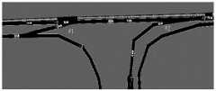
图1为本发明实例提供的交通场景。FIG. 1 is a traffic scene provided by an example of the present invention.
图2为本发明实例提供的自主驾驶车驾驶策略模型。FIG. 2 is a driving strategy model of an autonomous driving vehicle provided by an example of the present invention.
图3为本发明实例提供的车辆i和ip在Python中安全模式下的位置曲线。FIG. 3 is the position curve of vehicle i and ip in the safe mode in Python provided by the example of the present invention.
图4为本发明实例提供的车辆i和ip在Sumo中安全模式下的位置曲线。FIG. 4 is the position curve of vehicle i and ip in the safe mode in Sumo provided by the example of the present invention.
图5为本发明实例提供的车辆i和ip在Python中合并模式下的位置曲线。FIG. 5 is the position curve of vehicle i and ip in Python merge mode provided by the example of the present invention.
图6为本发明实例提供的车辆i和ip在Sumo中合并模式下的位置曲线。FIG. 6 is the position curve of vehicle i and ip in the merge mode in Sumo provided by the example of the present invention.
图7为本发明实例提供的车辆i,j和i-1在Python中安全合并模式下位置曲线。FIG. 7 is the position curve of vehicles i, j and i-1 in the safe merge mode in Python provided by the example of the present invention.
图8为本发明实例提供的车辆i,j和i-1在Sumo中安全合并模式下位置曲线。FIG. 8 is the position curve of vehicles i, j and i-1 in the safe merge mode in Sumo provided by the example of the present invention.
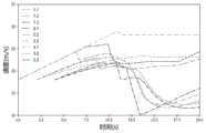
图9为本发明实例提供的基准情况下车辆的速度轨迹。FIG. 9 is the speed trajectory of the vehicle under the reference condition provided by the example of the present invention.
图10为本发明实例提供的最优轨迹下车辆的速度轨迹。FIG. 10 is the speed trajectory of the vehicle under the optimal trajectory provided by the example of the present invention.
图11为本发明实例提供的基准情况下车辆的位置轨迹。。FIG. 11 is the position track of the vehicle under the reference condition provided by the example of the present invention. .
图12为本发明实例提供的最优轨迹下车辆的位置轨迹。FIG. 12 is the position trajectory of the vehicle under the optimal trajectory provided by the example of the present invention.
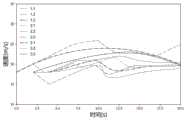
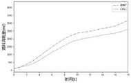
图13为本发明实例提供的车辆的平均速度曲线。FIG. 13 is an average speed curve of a vehicle provided by an example of the present invention.
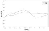
图14为本发明实例提供的车辆总油耗曲线。FIG. 14 is a vehicle total fuel consumption curve provided by an example of the present invention.
具体实施方式Detailed ways
以下将结合附图对本发明实例进行详细描述,以便本技术领域的人员更好地理解本发明。以下所描述的实例为本发明的一部分实例,并非全部实例。基于发明中的实例,本领域普通技术人员在没有做出创造性劳动的前提下所获得的所有其他实施例,都应当在本发明保护的范围之内。Examples of the present invention will be described in detail below with reference to the accompanying drawings, so that those skilled in the art can better understand the present invention. The examples described below are some, but not all, examples of the present invention. Based on the examples in the invention, all other embodiments obtained by those of ordinary skill in the art without creative efforts should fall within the protection scope of the present invention.
本发明中使用Python和微观交通仿真软件SUMO作为测试平台,首先通过Python实现车辆轨迹的理想仿真,然后通过SUMO中的交通控制接口(Traffic Control Interface,TraCI)与外界程序/算法实现互动,可以从SUMO中获取实时的交通信息,实现车辆轨迹验证和交通流仿真。以下对具体实施步骤进行详细说明。In the present invention, Python and microscopic traffic simulation software SUMO are used as test platforms. First, the ideal simulation of vehicle trajectory is realized through Python, and then the traffic control interface (Traffic Control Interface, TraCI) in SUMO is used to interact with external programs/algorithms. Real-time traffic information is obtained in SUMO to realize vehicle trajectory verification and traffic flow simulation. The specific implementation steps are described in detail below.
步骤1、实验场景设计
如图1所示,搭建了常见的城市快速路的匝道模型,以便于更好的描述匝道模型。如图2所示,根据图1的匝道模型,我们选取了北京东三环城市快速路入口匝道的实际场景作为仿真实验路网。该控制区域长350米,合并处#1位于主线170米处,辅路长度170米,合并处#2号位于主线350米处,辅路长度90米,车辆最终均通过合并区域#2离开控制区域。仿真实验中设置仿真步长为0.1s,根据图2的场景,我们为9辆车设计了3条不同的路线,来自一条主路和两条侧路的三辆车辆分别在0s、2s、4s时间以18米/秒的期望速度依次进入控制区。As shown in Figure 1, a ramp model of a common urban expressway is built to better describe the ramp model. As shown in Figure 2, according to the ramp model in Figure 1, we selected the actual scene of the on-ramp of the urban expressway in Beijing's East Third Ring Road as the simulation experimental road network. The control area is 350 meters long.
步骤2、仿真参数配置
为了使用本文提出的控制算法来评价相应的性能,我们提出了CAV市场渗透率为0%和100%的两种情况进行比较。在CAV渗透率为0%的情况下,采用SUMO中建立的IDM车辆跟随模型。其中IDM跟驰模型的公式如下:To evaluate the corresponding performance using the control algorithm proposed in this paper, we propose two cases of CAV market penetration of 0% and 100% for comparison. In the case of 0% CAV penetration, the IDM vehicle following model established in SUMO is adopted. The formula of the IDM car following model is as follows:


其中:睯为车辆最大加速度;v为车辆当前时速;v0为最大期望速度;δ为加速度指数;s*为期望间距函数;Δv为本车与前车速度差;s为车辆当前间距;s0为最小安全间距;T为车头时距;b为舒适减速度。Among them: 寯 is the maximum acceleration of the vehicle; v is the current speed of the vehicle; v0 is the maximum expected speed; δ is the acceleration index; s* is the desired distance function; Δv is the speed difference between the vehicle and the preceding vehicle;0 is the minimum safe distance; T is the headway; b is the comfortable deceleration.
在CAV渗透率为100%的情况下,采用python中搭建的最优控制模型,通过Traci将车辆动作传递给SUMO中相应车辆。仿真环境方面,配置参数如表1所示:When the CAV penetration rate is 100%, the optimal control model built in python is used to transmit vehicle actions to the corresponding vehicles in SUMO through Traci. In terms of simulation environment, the configuration parameters are shown in Table 1:
表1仿真环境参数配置Table 1 Simulation environment parameter configuration

步骤3、车辆信息获取Step 3. Obtain vehicle information
利用SUMO和Python搭建联合仿真平台,通过交通仿真软件获得车辆的ID、速度、位置、加速度等信息,调用Traci控制接口将SUMO仿真环境中获取的信息发送。Python获得消息后进行计算处理后,将车辆动作等控制信息发送回SUMO。Use SUMO and Python to build a co-simulation platform, obtain vehicle ID, speed, position, acceleration and other information through the traffic simulation software, and call the Traci control interface to send the information obtained in the SUMO simulation environment. After Python obtains the message and performs calculation processing, it sends control information such as vehicle motion back to SUMO.
步骤4、场景模式选择策略
本实例中选取的实验场景包含两个合并区域,车辆进入控制区域后,可能产生不同场景,因此,对应不同场景,采取不同的驾驶模式,以约束条件为分类标准,我们将智能网联车的驾驶模式分为以下几类:The experimental scene selected in this example includes two merged areas. After the vehicle enters the control area, different scenes may be generated. Therefore, corresponding to different scenes, different driving modes are adopted, and the constraints are used as the classification criteria. The driving modes are divided into the following categories:
a.智能网联车在驶入控制区域后,假设车辆遵循无约束行驶条件,根据无约束模式,求解车辆的最优轨迹,随后判断车辆是否违反前述约束,若不违反,则车辆遵循无约束模式下车辆最优轨迹。a. After the intelligent networked vehicle enters the control area, it is assumed that the vehicle follows the unconstrained driving conditions. According to the unconstrained mode, the optimal trajectory of the vehicle is solved, and then it is judged whether the vehicle violates the aforementioned constraints. If not, the vehicle follows the unconstrained mode. The optimal trajectory of the vehicle in the mode.
b.智能网联车在计算无约束模式轨迹后。如果车辆在某个时刻t1违反了安全约束或合并约束,为了避免车辆间冲突,我们需要重新规划一个满足约束的车辆轨迹,那么根据安全模式和合并模式求解车辆的最优轨迹。b. The ICV is after calculating the trajectory of the unconstrained mode. If the vehicle violates the safety constraint or the merging constraint at a certain timet1 , in order to avoid inter-vehicle conflict, we need to re-plan a vehicle trajectory that satisfies the constraint, then solve the optimal trajectory of the vehicle according to the safety mode and the merging mode.
c.基于单个入口匝道的合并情况,我们考虑了合并区段的一般情况——当车辆在多个合并区域都产生冲突时,即车辆违反了两个或多个约束条件,通过使用内点约束和在合并区域设置限制条件,实现多个入口匝道合并区段的协调。根据安全合并模式求解车辆的最优轨迹。c. Based on the merging case of a single on-ramp, we consider the general case of merging segments - when a vehicle collides in multiple merging areas, i.e. a vehicle violates two or more constraints, by using interior point constraints And set constraints in the merging area to achieve coordination of multiple on-ramp merging sections. Solve the optimal trajectory of the vehicle according to the safe merging mode.
步骤5:最优轨迹仿真验证Step 5: Optimal Trajectory Simulation Verification
根据步骤4中的分类,从步骤1场景中选取相应典型的情况,在Python中进行优化前后车辆的仿真,在SUMO中进行普通车辆和智能网联车的仿真对比。According to the classification in
a.安全模式仿真a. Safe Mode Emulation
假设车辆i和ip是在同一车道,并且都在无约束条件下进入控制区,车辆i和ip的初始参数
Ni(xi(t1),(vi(t1))=xi(t1)+φ·vi(t1)-xip(t1)=0Ni (xi (t1 ),(vi (t1 ))=xi( t1 )+φ·vi( t1 )-xip (t1 )=0
求解新的约束条件下的车辆轨迹如图3、4所示。无约束模式用于

b.单入匝道合并区安全合并模式仿真b. Simulation of safe merging mode in single on-ramp merging area
假设车辆i和i-1为不同车道车辆,驶入控制区域时均处于无约束状态。初始参数
c.多个入口匝道合并区段的安全合并模式模拟c. Simulation of Safe Merge Mode for Multiple On-Ramp Merging Sections
假设i和i-1为不同车道车辆,进入控制区域时均处于无约束状态。其中
步骤6:交通流仿真验证Step 6: Traffic flow simulation verification
为了评估和验证所提方法的有效性,我们使用微观交通模拟软件SUMO结合Python进行仿真。我们选择有两个相邻交汇区域的高速公路(交织区#1和交织区#2)进行实验,如图2所示。CAV渗透率为0%和100%的速度轨迹如图9和图10所示,速度轨迹如图11和图12所示。在CAV渗透率为0%的基准情景下,如图9、图11所示,当车辆较少时,车辆可以以更快的速度行驶。当车辆密度较高时,交通拥堵造成的走走停停对车辆的速度有很大的影响。因此我们可以看到,图10、图12中CAV的速度、位置波动较基线条件大大减小。当CAV渗透率为100%时,车辆进入控制区域时采用最优控制,车辆可以根据前车的轨迹预测前方是否会出现拥堵甚至碰撞,从而提前加速/减速。使CAV在控制区域发生碰撞时,能够更平稳地行驶,避免极端加速/减速。图13为控制区内所有车辆的瞬时平均速度。在最优控制下,与IDM模型相比,平均速度的波动有了很大的改善。图14显示了IDM场景和优化场景下所有车辆油耗的对比。该优化方法下,根据目标函数的行驶时间的计算公式
Claims (7)
Translated fromChinese


Priority Applications (1)
| Application Number | Priority Date | Filing Date | Title |
|---|---|---|---|
| CN202110182147.7ACN113011634B (en) | 2021-02-09 | 2021-02-09 | Intelligent network connection ramp merging method based on distributed optimal control |
Applications Claiming Priority (1)
| Application Number | Priority Date | Filing Date | Title |
|---|---|---|---|
| CN202110182147.7ACN113011634B (en) | 2021-02-09 | 2021-02-09 | Intelligent network connection ramp merging method based on distributed optimal control |
Publications (2)
| Publication Number | Publication Date |
|---|---|
| CN113011634Atrue CN113011634A (en) | 2021-06-22 |
| CN113011634B CN113011634B (en) | 2024-03-22 |
Family
ID=76402084
Family Applications (1)
| Application Number | Title | Priority Date | Filing Date |
|---|---|---|---|
| CN202110182147.7AActiveCN113011634B (en) | 2021-02-09 | 2021-02-09 | Intelligent network connection ramp merging method based on distributed optimal control |
Country Status (1)
| Country | Link |
|---|---|
| CN (1) | CN113011634B (en) |
Cited By (5)
| Publication number | Priority date | Publication date | Assignee | Title |
|---|---|---|---|---|
| CN114675655A (en)* | 2022-04-18 | 2022-06-28 | 北京京东乾石科技有限公司 | A vehicle control method and device |
| CN115032931A (en)* | 2022-06-15 | 2022-09-09 | 东南大学 | A Queue Convergence Control Method Based on Cluster Theory for Intelligent Networking |
| CN116052411A (en)* | 2022-11-17 | 2023-05-02 | 浙江工业大学 | Diversion area mixed traffic flow control method based on graph neural network reinforcement learning |
| CN116403436A (en)* | 2023-02-28 | 2023-07-07 | 武汉科技大学 | A Coordinated Control Method for Multi-vehicle Network |
| CN120412294A (en)* | 2025-07-03 | 2025-08-01 | 招商局重庆交通科研设计院有限公司 | A method, system, device and medium for controlling alternating traffic of autonomous vehicles |
Citations (4)
| Publication number | Priority date | Publication date | Assignee | Title |
|---|---|---|---|---|
| CN108806252A (en)* | 2018-06-19 | 2018-11-13 | 西南交通大学 | A kind of Mixed Freeway Traffic Flows collaboration optimal control method |
| CN111369813A (en)* | 2020-03-23 | 2020-07-03 | 江苏大学 | A collaborative control method and system for ramp splitting and merging of intelligent networked vehicles |
| CN111785088A (en)* | 2020-06-23 | 2020-10-16 | 大连理工大学 | A two-layer collaborative optimization method for ramp merging of connected vehicles |
| CN111968377A (en)* | 2020-08-31 | 2020-11-20 | 姜忠太 | Vehicle network-based vehicle track optimization method for fuel saving and driving comfort |
- 2021
- 2021-02-09CNCN202110182147.7Apatent/CN113011634B/enactiveActive
Patent Citations (4)
| Publication number | Priority date | Publication date | Assignee | Title |
|---|---|---|---|---|
| CN108806252A (en)* | 2018-06-19 | 2018-11-13 | 西南交通大学 | A kind of Mixed Freeway Traffic Flows collaboration optimal control method |
| CN111369813A (en)* | 2020-03-23 | 2020-07-03 | 江苏大学 | A collaborative control method and system for ramp splitting and merging of intelligent networked vehicles |
| CN111785088A (en)* | 2020-06-23 | 2020-10-16 | 大连理工大学 | A two-layer collaborative optimization method for ramp merging of connected vehicles |
| CN111968377A (en)* | 2020-08-31 | 2020-11-20 | 姜忠太 | Vehicle network-based vehicle track optimization method for fuel saving and driving comfort |
Cited By (6)
| Publication number | Priority date | Publication date | Assignee | Title |
|---|---|---|---|---|
| CN114675655A (en)* | 2022-04-18 | 2022-06-28 | 北京京东乾石科技有限公司 | A vehicle control method and device |
| CN115032931A (en)* | 2022-06-15 | 2022-09-09 | 东南大学 | A Queue Convergence Control Method Based on Cluster Theory for Intelligent Networking |
| CN116052411A (en)* | 2022-11-17 | 2023-05-02 | 浙江工业大学 | Diversion area mixed traffic flow control method based on graph neural network reinforcement learning |
| CN116403436A (en)* | 2023-02-28 | 2023-07-07 | 武汉科技大学 | A Coordinated Control Method for Multi-vehicle Network |
| CN120412294A (en)* | 2025-07-03 | 2025-08-01 | 招商局重庆交通科研设计院有限公司 | A method, system, device and medium for controlling alternating traffic of autonomous vehicles |
| CN120412294B (en)* | 2025-07-03 | 2025-09-12 | 招商局重庆交通科研设计院有限公司 | Automatic driving vehicle alternate passing control method, system, equipment and medium |
Also Published As
| Publication number | Publication date |
|---|---|
| CN113011634B (en) | 2024-03-22 |
Similar Documents
| Publication | Publication Date | Title |
|---|---|---|
| Liu et al. | An efficient on-ramp merging strategy for connected and automated vehicles in multi-lane traffic | |
| Wang et al. | Cooperative eco-driving at signalized intersections in a partially connected and automated vehicle environment | |
| CN113011634A (en) | Intelligent network connection ramp merging method based on distributed optimal control | |
| CN108538069B (en) | System and method for controlling vehicle speed in ramp merging area | |
| CN114067559B (en) | A merge optimization control method for automatic vehicle-only lanes merging into ordinary lanes | |
| CN115641717B (en) | Expressway mainline-ramp vehicle collaborative merging control method, equipment and storage medium based on mixed traffic flow | |
| CN114495547B (en) | A method for coordinated traffic at signalized intersections for autonomous vehicles | |
| CN112233413B (en) | A multi-lane spatiotemporal trajectory optimization method for intelligent networked vehicles | |
| CN112750318B (en) | Ramp confluence control method and system based on edge cloud | |
| CN115565390B (en) | Intelligent network-connected automobile multi-lane queue traffic control method, system and computer readable storage medium | |
| CN112185132A (en) | Coordination method for vehicle intersection without traffic light | |
| CN111243296B (en) | A Ramp Convergence Coordinated Control Method and System Based on Convergence Time Optimization | |
| Li et al. | A cooperative traffic control for the vehicles in the intersection based on the genetic algorithm | |
| CN111899509B (en) | A state vector calculation method for intelligent networked vehicles based on vehicle-road information coupling | |
| CN112258864B (en) | Method and system for automatic driving vehicle intersection scheduling based on sequence selection | |
| Ma et al. | A review of vehicle speed control strategies | |
| CN114999152A (en) | Edge cloud management and control method for ramp merge for mixed traffic flow | |
| CN119479283A (en) | A vehicle right-of-way decision and speed guidance method and system at an unsignalized intersection | |
| CN117351713A (en) | A collaborative traffic strategy for autonomous vehicle intersections based on precedence | |
| CN117133119A (en) | Time prediction-based priority driving control method for bus vehicles without dedicated lanes | |
| Shiomi et al. | A lane-change maneuver of automated vehicles for improving traffic flow on highways with multiple lanes | |
| CN116524735A (en) | A double-layer optimization control method and system for the merge area of an expressway entrance ramp | |
| CN115938118A (en) | No-signal intersection vehicle speed dynamic planning method based on road side guidance | |
| Yang et al. | Straight-going priority in hierarchical control framework for right-turning vehicle merging based on cooperative game | |
| Held et al. | Optimal speed control of a heavy-duty vehicle in the presence of traffic lights |
Legal Events
| Date | Code | Title | Description |
|---|---|---|---|
| PB01 | Publication | ||
| PB01 | Publication | ||
| SE01 | Entry into force of request for substantive examination | ||
| SE01 | Entry into force of request for substantive examination | ||
| GR01 | Patent grant | ||
| GR01 | Patent grant |