CN1129792C - Densitometer, test piece for densitometer, biosensor system, and method for forming terminal of test piece - Google Patents
Densitometer, test piece for densitometer, biosensor system, and method for forming terminal of test pieceDownload PDFInfo
- Publication number
- CN1129792C CN1129792CCN98807506ACN98807506ACN1129792CCN 1129792 CCN1129792 CCN 1129792CCN 98807506 ACN98807506 ACN 98807506ACN 98807506 ACN98807506 ACN 98807506ACN 1129792 CCN1129792 CCN 1129792C
- Authority
- CN
- China
- Prior art keywords
- electrode
- measuring device
- test strip
- concentration measuring
- potential
- Prior art date
- Legal status (The legal status is an assumption and is not a legal conclusion. Google has not performed a legal analysis and makes no representation as to the accuracy of the status listed.)
- Expired - Lifetime
Links
Images


Classifications
- G—PHYSICS
- G01—MEASURING; TESTING
- G01N—INVESTIGATING OR ANALYSING MATERIALS BY DETERMINING THEIR CHEMICAL OR PHYSICAL PROPERTIES
- G01N27/00—Investigating or analysing materials by the use of electric, electrochemical, or magnetic means
- G01N27/26—Investigating or analysing materials by the use of electric, electrochemical, or magnetic means by investigating electrochemical variables; by using electrolysis or electrophoresis
- G01N27/403—Cells and electrode assemblies
- G01N27/414—Ion-sensitive or chemical field-effect transistors, i.e. ISFETS or CHEMFETS
- C—CHEMISTRY; METALLURGY
- C12—BIOCHEMISTRY; BEER; SPIRITS; WINE; VINEGAR; MICROBIOLOGY; ENZYMOLOGY; MUTATION OR GENETIC ENGINEERING
- C12Q—MEASURING OR TESTING PROCESSES INVOLVING ENZYMES, NUCLEIC ACIDS OR MICROORGANISMS; COMPOSITIONS OR TEST PAPERS THEREFOR; PROCESSES OF PREPARING SUCH COMPOSITIONS; CONDITION-RESPONSIVE CONTROL IN MICROBIOLOGICAL OR ENZYMOLOGICAL PROCESSES
- C12Q1/00—Measuring or testing processes involving enzymes, nucleic acids or microorganisms; Compositions therefor; Processes of preparing such compositions
- C12Q1/001—Enzyme electrodes
- C12Q1/005—Enzyme electrodes involving specific analytes or enzymes
- C12Q1/006—Enzyme electrodes involving specific analytes or enzymes for glucose
- G—PHYSICS
- G01—MEASURING; TESTING
- G01N—INVESTIGATING OR ANALYSING MATERIALS BY DETERMINING THEIR CHEMICAL OR PHYSICAL PROPERTIES
- G01N27/00—Investigating or analysing materials by the use of electric, electrochemical, or magnetic means
- G01N27/26—Investigating or analysing materials by the use of electric, electrochemical, or magnetic means by investigating electrochemical variables; by using electrolysis or electrophoresis
- G01N27/28—Electrolytic cell components
- G01N27/30—Electrodes, e.g. test electrodes; Half-cells
- G01N27/327—Biochemical electrodes, e.g. electrical or mechanical details for in vitro measurements
- G01N27/3271—Amperometric enzyme electrodes for analytes in body fluids, e.g. glucose in blood
- G01N27/3272—Test elements therefor, i.e. disposable laminated substrates with electrodes, reagent and channels
- G—PHYSICS
- G01—MEASURING; TESTING
- G01N—INVESTIGATING OR ANALYSING MATERIALS BY DETERMINING THEIR CHEMICAL OR PHYSICAL PROPERTIES
- G01N33/00—Investigating or analysing materials by specific methods not covered by groups G01N1/00 - G01N31/00
- G01N33/48—Biological material, e.g. blood, urine; Haemocytometers
- G01N33/483—Physical analysis of biological material
- G01N33/487—Physical analysis of biological material of liquid biological material
- G01N33/4875—Details of handling test elements, e.g. dispensing or storage, not specific to a particular test method
- G01N33/48771—Coding of information, e.g. calibration data, lot number
Landscapes
- Health & Medical Sciences (AREA)
- Life Sciences & Earth Sciences (AREA)
- Chemical & Material Sciences (AREA)
- Engineering & Computer Science (AREA)
- Physics & Mathematics (AREA)
- Biomedical Technology (AREA)
- Immunology (AREA)
- Molecular Biology (AREA)
- General Health & Medical Sciences (AREA)
- Analytical Chemistry (AREA)
- Biochemistry (AREA)
- Biophysics (AREA)
- Organic Chemistry (AREA)
- Pathology (AREA)
- General Physics & Mathematics (AREA)
- Zoology (AREA)
- Proteomics, Peptides & Aminoacids (AREA)
- Wood Science & Technology (AREA)
- Hematology (AREA)
- Electrochemistry (AREA)
- Chemical Kinetics & Catalysis (AREA)
- General Engineering & Computer Science (AREA)
- Emergency Medicine (AREA)
- Medicinal Chemistry (AREA)
- Biotechnology (AREA)
- Microbiology (AREA)
- Food Science & Technology (AREA)
- Urology & Nephrology (AREA)
- Optics & Photonics (AREA)
- Genetics & Genomics (AREA)
- Bioinformatics & Cheminformatics (AREA)
- Microelectronics & Electronic Packaging (AREA)
- Investigating Or Analysing Biological Materials (AREA)
- Automatic Analysis And Handling Materials Therefor (AREA)
- Investigating Or Analyzing Materials By The Use Of Electric Means (AREA)
- Devices For Conveying Motion By Means Of Endless Flexible Members (AREA)
- Retarders (AREA)
- Surgical Instruments (AREA)
- Investigating Or Analysing Materials By Optical Means (AREA)
- Investigating Or Analyzing Non-Biological Materials By The Use Of Chemical Means (AREA)
Abstract
Description
Translated fromChinese技术领域technical field
本发明涉及一种使用生物传感器测量在一种溶液中的特定的成分的浓度的浓度测量装置,将被用于该浓度测量装置的一种试片,使用该浓度测量装置和试片的一种生物传感器系统,以及用于在该试片上形成端子的一种方法。将被测量的溶液具体地说是体液,例如,血、血浆、尿、唾液等等。尤其血是经常使用的。The present invention relates to a concentration measuring device for measuring the concentration of a specific component in a solution using a biosensor, a test strip to be used for the concentration measuring device, and one of the concentration measuring device and the test strip to be used A biosensor system, and a method for forming terminals on the strip. The solution to be measured is specifically a body fluid such as blood, plasma, urine, saliva, and the like. Especially blood is often used.
背景技术Background technique
目前使用生物传感器的测量装置实际应用于定量检测活体的体液中一种特定的成分,比如,血、尿等等。在这类测量装置中,一种简洁的并且可任意使用的试片被适宜当做生物传感器,例如,血被滴在试片上,从而测量血液中的葡萄糖、乳酸、胆固醇等等的浓度。Currently, measuring devices using biosensors are practically applied to quantitatively detect a specific component in body fluids of living organisms, such as blood, urine, and the like. In this type of measuring device, a compact and disposable test strip is suitable as a biosensor, for example, blood is dropped on the test strip to measure the concentration of glucose, lactic acid, cholesterol, etc. in the blood.
例如,在日本的专利公开出版物4-357452中披露了上述的方法和试片的结构。 现有技术的试片是如图33所示的构成的。具体地说,传导碳糊或类似物质被网格印刷在一片隔离基底材料2的片上,从而在基底材料2的纵方向的未端部分形成彼此邻近的端子3、4。端子3、4在纵方向扩展以在该基底材料2的另外一个未端部分形成一个测量电极5和面对该测量电极5的一个相反的电极6。一隔离层被形成在除了端子3、4,测量电极5和相反的电极6上之外的该隔离基底材料上。与将被测量的成分相对应的由酶、介质等等构成的一种反应试剂(未示出)被施加在测量电极5和相反的电极6上。一个封面8通过一间隔物7覆盖在除端子3、4之外的基底材料2的上面。因此获得图34的一种试片1。形成一个突出部分10以至于防止该试片1对测量装置被以一个错误的方向设置。For example, the above method and the structure of the test piece are disclosed in Japanese Patent Laid-Open Publication No. 4-357452. The test piece of prior art is constituted as shown in Figure 33. Specifically, conductive carbon paste or the like is screen-printed on a sheet of
如在现有技术4-357452中所披露的,试片1是自端子3、4一侧被插入到如图35所示的卡形测量装置20的设置部分21。在测量装置20的表面设置一个显示部分22以便显示测量结果。传统的测量装置20的设置部分21具有当试片1被设置到测量装置20时,将电连接到试片1的端子3、4的一正电极和一负电极。As disclosed in prior art 4-357452, the
在试片1被设置到测量装置20中之后,从现有技术4-357452中清楚的看到,血是点滴在试片1的另外一个未端部分,通过毛细管作用其被吸引到形成在间隔物7中的一个空间9,达到施加在测量电极5和相反的电极6反应试剂,并且与反应试剂起反应。然后,一个电压从测量装置20施加到试片1的端子3、4,因此通过与酶反应使反应产物被氧化。在该测量装置20测量在这个氧化中产生的电流。该被测量的氧化电流被转换成将被测量的特定的成分的浓度。After the
使用的反应试剂是,例如,包括当在溶液中葡萄糖将被测量时作为酶的葡萄糖氧化酶,或者是,包括当在溶液中乳酸、胆固醇将被测量时的乳酸盐氧化酶、胆固醇氧化酶,如在日本专利公开号为8-278276的公开的说明书中所透露的。The reaction reagent used is, for example, including glucose oxidase as an enzyme when glucose is to be measured in a solution, or is including lactate oxidase, cholesterol oxidase when lactic acid, cholesterol are to be measured in a solution , as disclosed in the published specification of Japanese Patent Laid-Open No. 8-278276.
从上面的描述中显然可以看出,通过更换包含在反应试剂中的酶能够获得对应于将被测量的每个成分的试片,而不必改变基本的试片1。换言之,这些试片的结构可以被做成对于将被测量的各种成分是通用的,用于这些试片的测量装置和制造设备可以是共享的,具有使制造测量装置和试片的费用降低的效果。虽然理想的情况是用于相对应的各种成分的试片要求处在相同的地位,但事实上,用于葡萄糖的试片需要量是最大的,而用于乳酸的或者胆固醇的试片的需要量是较小的。在上述的无规律的需求中,如果试片是以相同的结构构成的,那么仅仅通过改变反应试剂就可获得该无规律需求的试片。As apparent from the above description, the test strip corresponding to each component to be measured can be obtained by replacing the enzyme contained in the reaction reagent without changing the
然而,如果在试片的共用结构中,变得非常难区别试片,例如,在葡萄糖的试片和乳酸的试片之间区别。可能发生的情况是,即使葡萄糖的浓度是所需的,由于不经意乳酸试片被设置到测量装置中。因此,获得不正确的结果。However, if in the common structure of the test strips, it becomes very difficult to distinguish the test strips, for example, between the test strips of glucose and the test strips of lactic acid. It may happen that, even though the glucose concentration is desired, the lactate test strip is inadvertently set into the measuring device. Therefore, incorrect results are obtained.
本发明通过设计以解决上面描述的不当之处,其目的是提供一个浓度测量装置,用于该浓度测量装置的试片,一生物传感器系统,以及用于在该试片上形成端子的方法,从而对试片上的目标成分进行测量。The present invention is designed to solve the disadvantages described above, and its object is to provide a concentration measuring device, a test strip for the concentration measuring device, a biosensor system, and a method for forming terminals on the test strip, thereby Measure the target component on the test strip.
发明的公开disclosure of invention
在实现这些和其他特征方面,根据本发明的第一方面,提供了对其设置一试片的一种浓度测量装置,该试片包括在基底材料上的与液体检验样品起反应的反应试剂,一个正极端子,以及一个负极端子,这些端子基于反应试剂的反应电检测在液体检验样品中特定的成分的浓度,浓度测量装置包括将分别地与试片的正极端子和负极端子电连接的一正电极和一负电极,从而通过正电极和负电极对液体检验样品中的特定成分的浓度起作用,该浓度测量装置其特征在于更进一步包括一个类型判断电极,用于判断形成在被设置到浓度测量装置的试片上的反应试剂的类型,该类型判断电极是与正电极和负电极分离地设置的。In achieving these and other features, according to a first aspect of the present invention, there is provided a concentration measuring device provided therewith with a test strip comprising a reaction reagent reacting with a liquid test sample on a base material, A positive terminal, and a negative terminal, these terminals electrically detect the concentration of a specific component in the liquid test sample based on the reaction of the reaction reagent, and the concentration measuring device includes a positive terminal to be electrically connected to the positive terminal and the negative terminal of the test strip, respectively. electrode and a negative electrode, thereby acting on the concentration of a specific component in the liquid test sample through the positive electrode and the negative electrode, the concentration measuring device is characterized in that it further includes a type judgment electrode for judging the The type of the reaction reagent on the test strip of the measuring device, the type judgment electrode is provided separately from the positive electrode and the negative electrode.
如上面所描述的,在本发明第一方面的浓度测量装置中,该类型判断电极是与正电极和负电极分离地附加的。因此,该将被测量的特定成分可以通过该试片测量,该试片是适合于利用类型判断电极测量特定成分的。As described above, in the concentration measuring device of the first aspect of the present invention, the type judging electrode is attached separately from the positive electrode and the negative electrode. Therefore, the specific component to be measured can be measured by the test strip which is suitable for measuring the specific component using the type judgment electrode.
根据本发明的第二方面,浓度测量装置还可以包括一第一识别装置,其根据一个事实,即仅当能够测量特定的成分的试片被设置到浓度测量装置且类型判断电极被连接到正电极时,用于输送与用于液体检验样品的能够测量特定成分的试片相对应的信息,以及According to the second aspect of the present invention, the concentration measuring device may further include a first identification device based on the fact that only when a test strip capable of measuring a specific component is set to the concentration measuring device and the type judgment electrode is connected to the positive electrodes, for delivering information corresponding to test strips capable of measuring specific components for liquid test samples, and
一个第二识别装置,其根据从第一识别装置馈入的信息识别试片。A second identifying means identifies the test strip based on the information fed from the first identifying means.
根据本发明第二方面的浓度测量装置,第一和第二识别装置还被设置在第一实施例的测量装置中,其展现下列效果。 当设置了能够测量将被测量的成分的试片时,随着设置的试片的类型信息从第一识别装置被发送,类型判断电极和正电极彼此连接。第二识别装置根据类型信息,识别与测量装置适合的一试片被设置。相应地将被测量的成分可以通过与测量装置适合的该试片被测量。According to the concentration measuring device of the second aspect of the present invention, the first and second identifying means are also provided in the measuring device of the first embodiment, which exhibits the following effects. When a test strip capable of measuring a component to be measured is set, as type information of the set test strip is transmitted from the first identification device, the type judging electrode and the positive electrode are connected to each other. According to the type information, the second identifying means identifies a test piece suitable for the measuring means to be set. The corresponding component to be measured can be measured by means of the test strip which is suitable for the measuring device.
根据本发明的第三方面,浓度测量装置可以包括用于连接或者断开类型判断电极和正电极的和用于连接或者断开类型判断电极和负电极的开关,以及一个识别装置,其根据随着每个开关的接通/断开从正电极的检测部分获得的消息,用于识别用于液体检验样品的能够测量特定成分的试片被设置到该浓度测量装置。According to the third aspect of the present invention, the concentration measuring device may include a switch for connecting or disconnecting the type judging electrode and the positive electrode and a switch for connecting or disconnecting the type judging electrode and the negative electrode, and a discriminating means according to the The ON/OFF of each switch obtains a message from the detection portion of the positive electrode for identifying that a test strip capable of measuring a specific component for a liquid test sample is set to the concentration measuring device.
根据本发明第三方面的浓度测量装置,第一实施例的浓度测量装置还设置有开关和识别装置,其展现下列效果。该识别装置可以根据随着开关的接通/断开产生在正电极的检测部分的信息,判断是不是符合该测量装置的试片被设置。因此,将被测量的成分可以通过与测量装置适合的试片被测量。According to the concentration measuring device of the third aspect of the present invention, the concentration measuring device of the first embodiment is further provided with a switch and identification means, which exhibit the following effects. The identifying means can judge whether or not the test piece corresponding to the measuring means is set based on the information generated in the detecting portion of the positive electrode as the switch is turned on/off. Therefore, the component to be measured can be measured by a test piece suitable for the measuring device.
根据本发明的第四方面,浓度测量装置还可以包括一个电势判断装置,其与类型判断电极连接,判断电极判断电极是不是变成一个适合的试片设置电势,该电势是当用于液体检验样品的能够测量特定成分的试片被设置到浓度测量装置时在类型判断电极产生的电势。According to the fourth aspect of the present invention, the concentration measuring device may also include a potential judging device, which is connected to the type judging electrode, and judges whether the judging electrode becomes a suitable test strip setting potential, which is used for liquid testing. The potential generated at the type judgment electrode when a test strip capable of measuring a specific component of a sample is set to a concentration measuring device.
根据本发明的第四方面,电势判断装置被包括在第一实施例的浓度测量装置中。电势判断装置检测类型判断电极的电势,从而判断该电势是不是适合的试片设置电势。当该电势是该适合试片设置电势时,该电势判断装置断定适合于该浓度测量装置的试片被设置。相应地,将被测量的成分可以通过符合测量装置的试片测量。According to a fourth aspect of the present invention, the potential judging means is included in the concentration measuring device of the first embodiment. The potential judging device detects the potential of the type judging electrode, thereby judging whether the potential is a suitable setting potential of the test piece. When the potential is the suitable test strip setting potential, the potential judging means judges that the test strip suitable for the concentration measuring device is set. Accordingly, the component to be measured can be measured by a test strip conforming to the measuring device.
根据本发明的第五方面,浓度测量装置还可以包括一个变化判断装置,其与类型判断电极连接,类型判断电极判断电极是不是有对应于适合的试片设置变化的一个电势变化,该变化是当用于液体检验样品的能够测量特定成分的试片被设置到浓度测量装置时在类型判断电极产生的变化。According to a fifth aspect of the present invention, the concentration measuring device may further include a change judging device connected to the type judging electrode, and the type judging electrode judges whether the electrode has a potential change corresponding to a suitable test strip setting change, and the change is The change that occurs at the type judgment electrode when a test strip capable of measuring a specific component for a liquid test sample is set to a concentration measuring device.
根据本发明的第五方面的浓度测量装置具有被加到第一实施例的浓度测量装置中的变化判断装置。更具体地说,当试片被设置到测量装置时,变化判断装置检测在类型判断电极的电势变化,从而判断该电势变化是不是对应于适合的试片设置变化。如果该电势变化是适合的试片设置变化,这个变化判断装置断定与该测量装置相配的试片被设置。因此可以通过与测量装置相配的试片测量成分。A concentration measuring device according to a fifth aspect of the present invention has the change judging means added to the concentration measuring device of the first embodiment. More specifically, when the test strip is set to the measuring device, the change judging means detects a potential change at the type judging electrode, thereby judging whether the potential change corresponds to an appropriate test strip setting change. If the potential change is a suitable test piece setting change, the change judging means judges that the test piece matching the measuring device is set. Therefore, the composition can be measured by the test strip matched with the measuring device.
根据本发明的第六方面,提供了一种将被设置到本发明的第二方面中的浓度测量装置的试片,其特征在于包括将与类型判断电极和正电极电连接的一个类型判断端子,从而允许浓度测量装置的第一识别装置发送与用于液体检验样品的能够测量特定成分的试片相对应的信息。According to a sixth aspect of the present invention, there is provided a test strip to be set to the concentration measuring device in the second aspect of the present invention, characterized in comprising a type judgment terminal to be electrically connected to the type judgment electrode and the positive electrode, This allows the first identification means of the concentration measuring device to transmit information corresponding to the test strip capable of measuring a specific component for the liquid test sample.
根据本发明的第六方面,设置到本发明第二方面的浓度测量装置的试片具有类型判断端子。由于试片与测量装置适合的信息是从第一识别装置发送的,所以试片可使测量装置断定适合于该测量装置的试片被设置。According to a sixth aspect of the present invention, the test piece provided to the concentration measuring device of the second aspect of the present invention has a type judgment terminal. Since the information that the test strip is suitable for the measuring device is transmitted from the first identification device, the test strip can cause the measuring device to judge that the test strip suitable for the measuring device is set.
根据本发明的第七方面,提供了一种将被设置到本发明的第四方面中的浓度测量装置的试片,其特征在于包括将与类型判断电极和正电极电连接的一个类型判断端子,并允许电势判断装置判断在类型判断电极的电势是适合的试片设置电势。According to a seventh aspect of the present invention, there is provided a test strip to be set to the concentration measuring device in the fourth aspect of the present invention, characterized in comprising a type judgment terminal to be electrically connected to the type judgment electrode and the positive electrode, And allow the potential judging device to judge that the potential of the type judging electrode is suitable for setting the potential of the test piece.
在本发明的第七方面中,试片被设置到第四方面的浓度测量装置,其具有类型判断端子。该试片允许电势判断装置判断在类型判断电极上的电势是适合的试片设置电势。第七方面的试片允许测量装置判断适合的试片被设置到该测量装置。In a seventh aspect of the present invention, the test piece is set to the concentration measuring device of the fourth aspect, which has a type judgment terminal. The test strip allows the potential judgment means to judge that the potential on the type judgment electrode is an appropriate test strip setting potential. The test strip of the seventh aspect allows the measuring device to judge that a suitable test strip is set to the measuring device.
根据本发明的第八方面,提供了一种将被设置到本发明的第五方面中的浓度测量装置的试片,其特征在于包括将与类型判断电极和正电极电连接的一个类型判断端子,并允许变化判断装置判断在类型判断电极的变化对应于适合的试片设置变化。According to an eighth aspect of the present invention, there is provided a test strip to be set to the concentration measuring device in the fifth aspect of the present invention, characterized in comprising a type judgment terminal to be electrically connected to the type judgment electrode and the positive electrode, And allow the change judging device to judge that the change in the type judging electrode corresponds to a suitable test strip setting change.
根据第八方面,试片被设置到第五方面的测量装置并且具有类型判断端子。因此变化判断装置可以通过一个适合的试片判断类型判断电极的电势显示的变化。该试片允许测量装置判断适合的试片被设置。According to an eighth aspect, the test piece is set to the measuring device of the fifth aspect and has a type judgment terminal. Therefore, the change judging means can judge the change of the potential display of the electrode by a suitable test strip judging type. The test strip allows the measuring device to judge that a suitable test strip is set.
根据本发明的第九方面,提供了一种生物传感器系统,其特征在于包括:According to a ninth aspect of the present invention, a biosensor system is provided, characterized in that it comprises:
第一浓度测量装置,其包括根据第二方面的浓度测量装置,其中正电极、类型判断电极以及负电极是按此顺序与试片的设置方向成直角排列;A first concentration measuring device comprising the concentration measuring device according to the second aspect, wherein the positive electrode, the type judgment electrode, and the negative electrode are arranged in this order at right angles to the direction in which the test piece is arranged;
第一试片,其包括根据第六方面的试片,其包括将与正电极和类型判断电极电连接的一个第一端子,将与负电极电连接的一个第二端子;a first test strip, which includes the test strip according to the sixth aspect, which includes a first terminal to be electrically connected to the positive electrode and the type judgment electrode, and a second terminal to be electrically connected to the negative electrode;
第二浓度测量装置,其包括根据第二方面的浓度测量装置,其中正电极、负电极以及类型判断电极是按此顺序(与试片的设置方向)成直角排列的;以及A second concentration measuring device comprising the concentration measuring device according to the second aspect, wherein the positive electrode, the negative electrode, and the type judging electrode are arranged in this order at right angles to the direction in which the test strip is arranged; and
一第二试片,其包括根据第六方面的将被设置到第二浓度测量装置的试片,其包括将与正电极和类型判断电极电连接的一个第一端子,从而让第二浓度装置的第一识别装置输送与对该液体检验样品能够测量该特定成分的该试片相对应的信息;以及将与负电极电连接的一个第二端子,A second test strip, which includes the test strip to be set to the second concentration measuring device according to the sixth aspect, which includes a first terminal to be electrically connected to the positive electrode and the type judgment electrode, so that the second concentration device a first identification means delivering information corresponding to the test strip capable of measuring the specific component of the liquid test sample; and a second terminal to be electrically connected to the negative electrode,
所述生物传感器系统构成为以致如果第一试片被设置到第二浓度测量装置,以及如果第二试片被设置到第一浓度测量装置,那么不能进行该特定成分的浓度检测。The biosensor system is configured such that concentration detection of the specific component cannot be performed if the first test strip is set to the second concentration measuring device, and if the second test strip is set to the first concentration measuring device.
根据本发明第九方面的生物传感器系统被构制成一种试片仅仅适合一种浓度测量装置,使得在不同的种类之中不可能共享试片和浓度测量装置。The biosensor system according to the ninth aspect of the present invention is configured such that one test strip fits only one kind of concentration measuring device, so that it is impossible to share the test strip and the concentration measuring device among different kinds.
根据本发明的第十方面,在第五方面的浓度测量装置中,变化判断装置可以存储多个校准曲线信息,用于补偿在液体检验样品中特定成分浓度测量中的误差,According to a tenth aspect of the present invention, in the concentration measuring device of the fifth aspect, the change judging means may store a plurality of calibration curve information for compensating errors in the concentration measurement of specific components in the liquid test sample,
当浓度测量装置可以测量唯一的一个特定的成分的浓度,以及具有与该特定的成分起反应的反应试剂的并且能够通过该浓度测量装置测量该特定的成分的浓度的试片被设置到该浓度测量装置时,在类型判断电极检测一个校准曲线信息选择变化,以至于在多个校准曲线信息之中选择一个需要的校准曲线信息,代替在类型判断电极的适当的试片设置变化的存在/不存在,以及When the concentration measuring device can measure only the concentration of a specific component, and a test strip having a reaction reagent that reacts with the specific component and capable of measuring the concentration of the specific component by the concentration measuring device is set to the concentration When measuring the device, a calibration curve information selection change is detected at the type judging electrode so that a desired calibration curve information is selected among a plurality of calibration curve information instead of the presence/absence of an appropriate test piece setting change at the type judging electrode exist, and
基于根据检测的校准曲线信息选择变化选择的校准曲线信息,补偿误差。The error is compensated based on the selected calibration curve information according to the selected variation of the detected calibration curve information.
根据第十方面中的浓度测量装置,校准曲线信息选择变化被检测,代替了在第五方面的测量装置中的对适合的试片设置变化的存在/不存在的检测。校准曲线信息可以是根据上面的检测选择的,并且测量误差可以通过选择的校准曲线信息补偿。相应地,可以获得更高准确性的特定成分的浓度。According to the concentration measuring device in the tenth aspect, the calibration curve information selection change is detected instead of the detection of the presence/absence of the change in the appropriate test strip setting in the measuring device in the fifth aspect. Calibration curve information may be selected according to the above detection, and measurement errors may be compensated by the selected calibration curve information. Accordingly, the concentration of a specific component can be obtained with higher accuracy.
根据本发明的十一方面,在第五方面的浓度测量装置中,变化判断装置可以存储多个校准曲线信息,用于补偿在液体检验样品中特定成分浓度测量中的误差,According to an eleventh aspect of the present invention, in the concentration measuring device of the fifth aspect, the change judging device may store a plurality of calibration curve information for compensating errors in the concentration measurement of specific components in the liquid test sample,
根据包括在类型判断电极上的适合的试片设置变化中的校准曲线信息选择变化,在多个校准曲线信息之中选择一个所需的校准曲线信息,以及根据在类型判断电极的适合试片设置变化判断试片的类型,以及Selecting a change based on calibration curve information included in a suitable test strip setting change on a type judging electrode, selecting a desired calibration curve information among a plurality of calibration curve information, and selecting a desired calibration curve information based on a suitable test strip setting on a type judging electrode change the type of judgment test piece, and
根据选择的校准曲线信息补偿误差。Errors are compensated based on the selected calibration curve information.
根据该第十一方面,在第五方面的浓度测量装置中,除了适合的试片设置变化存在/不存在的检测之外还检测该校准曲线信息选择变化,因此对应于设置到测量装置的试片的被检测出的类型的校准曲线信息和许多试片产品可以被选择。According to the eleventh aspect, in the concentration measuring device of the fifth aspect, the calibration curve information selection change is detected in addition to the detection of the presence/absence of the appropriate test strip setting change, thus corresponding to the test piece set to the measuring device. Calibration curve information for the type of strip tested and a number of strip products can be selected.
根据本发明的第十二方面,提供了一种将被设置到本发明的第十方面中的浓度测量装置的试片,其特征在于有将与类型判断电极电连接的一个类型判断端子,并允许变化判断装置根据在类型判断电极的电势检测校准曲线信息选择变化,用于在多个校准曲线信息之中选择所需的校准曲线信息。According to a twelfth aspect of the present invention, there is provided a test strip to be provided to the concentration measuring device in the tenth aspect of the present invention, characterized in that there is a type judgment terminal to be electrically connected to the type judgment electrode, and The variation judging means is allowed to select a variation according to the potential detection calibration curve information at the type judging electrode for selecting required calibration curve information among a plurality of calibration curve information.
根据本发明的第十二方面,试片被设置到第十方面的浓度测量装置中。该试片装备有用于检测校准曲线信息选择变化的类型判断端子,因此允许变化判断装置选择该校准曲线信息。According to a twelfth aspect of the present invention, the test piece is set in the concentration measuring device of the tenth aspect. The test strip is equipped with a type judgment terminal for detecting a selection change of the calibration curve information, thereby allowing the change judgment means to select the calibration curve information.
根据本发明的第十三方面,提供了一种将被设置到本发明的第十一方面中的浓度测量装置的试片,其特征在于通过将与类型判断电极电连接的一个类型判断端子,并为了判断试片的类型允许变化判断装置判断在类型判断电极的电势变化是适合的试片设置变化,并且还允许变化判断装置检测校准曲线选择信息变化以便在多个校准曲线信息之中选择所需的校准曲线信息。According to a thirteenth aspect of the present invention, there is provided a test piece to be set to the concentration measuring device in the eleventh aspect of the present invention, characterized in that by a type judgment terminal to be electrically connected with the type judgment electrode, And allows the change judging means to judge that the potential change at the type judging electrode is an appropriate test strip setting change for judging the type of the test strip, and also allows the change judging means to detect a change in the calibration curve selection information so as to select a selected one among a plurality of calibration curve information required calibration curve information.
根据本发明第十三方面的试片被设置到第十方面的浓度测量装置中,其包括类型判断端子,用于检测校准曲线信息选择变化以及适合的试片设置变化的存在/不存在。因此,该第十三方面的试片允许变化判断装置判断可由设置到测量装置的试片测量的这种特定成分,而且选择校准曲线信息。The test strip according to the thirteenth aspect of the present invention is set into the concentration measuring device of the tenth aspect, which includes a type judgment terminal for detecting the presence/absence of selection change of calibration curve information and appropriate test strip setting change. Therefore, the test strip of the thirteenth aspect allows the change judging means to judge such specific components measurable by the test strip set to the measuring means, and to select calibration curve information.
根据本发明的第十四方面,提供了一种用于制造第十二和第十三方面的试片的方法,其特征在于包括:According to a fourteenth aspect of the present invention, there is provided a method for manufacturing the test pieces of the twelfth and thirteenth aspects, characterized in that it comprises:
制备试片的基底材料;Prepare the base material of the test piece;
在试片的基底材料上用导电材料形成正极端子和负极端子;Forming a positive terminal and a negative terminal with a conductive material on the base material of the test piece;
在试片的基底材料上施加反应试剂;Applying a reaction reagent on the base material of the test piece;
将具有浓度已知的特定成分的一种标准溶液点滴到该被施加的反应试剂上;spotting a standard solution having a specific component of known concentration onto the applied reagent;
选择补偿基于反应检测的浓度和已知的该特定成分的浓度之间的误差的校准曲线信息;以及selecting calibration curve information that compensates for the error between the concentration detected based on the reaction and the known concentration for that particular component; and
形成类型判断端子,从而在类型判断端子产生至少指示被选择的校准曲线信息的校准曲线信息选择变化。The type judging terminal is formed such that a calibration curve information selection change indicating at least the selected calibration curve information is generated at the type judging terminal.
在用于形成根据该第十四方面的试片的端子的方法中,在校准曲线信息被选择之后,类型判断端子被形成到第十二、第十三方面的试片上,以导致校准曲线信息选择变化。附图的简短的描述In the method for forming the terminals of the test strip according to the fourteenth aspect, after the calibration curve information is selected, the type judgment terminal is formed on the test strips of the twelfth and thirteenth aspects to result in the calibration curve information Choose Variations. A brief description of the drawings
从下面参照附图与本发明实施例相结合的描述,本发明的这些和其它特征将变得更加明显,在其中:These and other features of the invention will become more apparent from the following description taken in conjunction with the embodiments of the invention, with reference to the accompanying drawings, in which:
图1是根据本发明的第一实施例的浓度测量装置的结构图;1 is a structural diagram of a concentration measuring device according to a first embodiment of the present invention;
图2是将被设置到浓度测量装置并且与图1的浓度测量装置适合的一个试片的平面图;Fig. 2 is a plan view of a test strip to be set to the concentration measuring device and suitable for the concentration measuring device of Fig. 1;
图3是将被设置到浓度测量装置并且与图1的浓度测量装置不相适合的一个试片的平面图;Fig. 3 is a plan view of a test strip to be set to the concentration measuring device and not suitable for the concentration measuring device of Fig. 1;
图4是根据本发明的第二实施例的浓度测量装置的结构图;4 is a structural diagram of a concentration measuring device according to a second embodiment of the present invention;
图5是将被设置到浓度测量装置并且与图4的浓度测量装置适合的一个试片的平面图;Figure 5 is a plan view of a test strip to be set to the concentration measuring device and suitable for the concentration measuring device of Figure 4;
图6是将被设置到浓度测量装置并且与图4的浓度测量装置不相适合的一个试片的平面图;Fig. 6 is a plan view of a test strip to be set to the concentration measuring device and not suitable for the concentration measuring device of Fig. 4;
图7是根据本发明的第三实施例的浓度测量装置的结构图;7 is a structural diagram of a concentration measuring device according to a third embodiment of the present invention;
图8是将被设置到浓度测量装置并且与图7的浓度测量装置适合的一个试片的平面图;Figure 8 is a plan view of a test strip to be set to the concentration measuring device and suitable for the concentration measuring device of Figure 7;
图9是将被设置到浓度测量装置并且与图7的浓度测量装置不相适合的一个试片的平面图;Fig. 9 is a plan view of a test strip to be set to the concentration measuring device and not suitable for the concentration measuring device of Fig. 7;
图10是一个用于识别在图7的浓度测量装置中的试片的操作的流程图;Fig. 10 is a flowchart for identifying the operation of the test strip in the concentration measuring device of Fig. 7;
图11是根据本发明的第四实施例的浓度测量装置的结构图;11 is a structural diagram of a concentration measuring device according to a fourth embodiment of the present invention;
图12是将被设置到浓度测量装置并且与图11的浓度测量装置适合的一个试片的平面图;Figure 12 is a plan view of a test strip to be set to the concentration measuring device and suitable for the concentration measuring device of Figure 11;
图13是将被设置到浓度测量装置并且与图11的浓度测量装置不相适合的一个试片的平面图;Fig. 13 is a plan view of a test strip to be set to the concentration measuring device and not suitable for the concentration measuring device of Fig. 11;
图14是一个用于识别在图11的浓度测量装置中的试片的操作的流程图;Fig. 14 is a flowchart for identifying the operation of the test strip in the concentration measuring device of Fig. 11;
图15是将被设置到图11的浓度测量装置的一个不同的实施例的试片的平面图;Fig. 15 is a plan view of a test strip to be set to a different embodiment of the concentration measuring device of Fig. 11;
图16是图1的浓度测量装置的一个修改的例子的示图;FIG. 16 is a diagram of a modified example of the concentration measuring device of FIG. 1;
图17是适合于图16的浓度测量装置的一个试片的平面图;Fig. 17 is a plan view of a test piece suitable for the concentration measuring device of Fig. 16;
图18是示出图4的浓度测量装置的操作的一个流程图;Fig. 18 is a flowchart showing the operation of the concentration measuring device of Fig. 4;
图19是根据本发明的第五实施例的浓度测量装置的结构图;19 is a structural diagram of a concentration measuring device according to a fifth embodiment of the present invention;
图20是将被设置到图19的浓度测量装置的一个试片的平面图;Fig. 20 is a plan view of a test strip to be set to the concentration measuring device of Fig. 19;
图21是图19的浓度测量装置的一个改型的结构示图;Fig. 21 is a structural diagram of a modification of the concentration measuring device of Fig. 19;
图22是将被设置到图21的浓度测量装置的一个试片的平面图;Fig. 22 is a plan view of a test strip to be set to the concentration measuring device of Fig. 21;
图23是图19的浓度测量装置的一个不同的改型的结构示图;Fig. 23 is a structural diagram of a different modification of the concentration measuring device of Fig. 19;
图24是将被设置到图23的浓度测量装置的一个试片的平面图;Fig. 24 is a plan view of a test strip to be set to the concentration measuring device of Fig. 23;
图25是用于在图20、22和24中的每一试片中形成端子的第一形成方法的说明性示图;25 is an explanatory view of a first forming method for forming terminals in each of the test pieces in FIGS. 20, 22 and 24;
图26是用于在图20、22和24的每一试片中形成端子的第一形成方法的说明的示图;FIG. 26 is a diagram for explaining a first forming method for forming terminals in each of the test pieces of FIGS. 20, 22 and 24;
图27是用于在图20、22和24的每一试片中形成端子的第一形成方法的说明的示图;FIG. 27 is a view for explaining a first forming method for forming terminals in each of the test pieces of FIGS. 20, 22 and 24;
图28是用于在图20、22和24的每一试片中形成端子的第一形成方法的说明的示图;FIG. 28 is a view for explaining a first forming method for forming terminals in each of the test pieces of FIGS. 20, 22 and 24;
图29是用于在图20、22和24的每一试片中形成端子的一个第二形成方法的说明的示图;FIG. 29 is a view for illustrating a second forming method for forming terminals in each of the test pieces of FIGS. 20, 22 and 24;
图30是用于在图20、22和24的每一试片中形成端子的第二形成方法的说明的示图;FIG. 30 is a view for explaining a second forming method for forming terminals in each of the test pieces of FIGS. 20, 22 and 24;
图31是用于在图20、22和24的每一试片中形成端子的第二形成方法的说明的示图;FIG. 31 is a view for explaining a second forming method for forming terminals in each of the test pieces of FIGS. 20, 22 and 24;
图32是用于在图20、22和24的每一试片中形成端子的第二形成方法的说明的示图;FIG. 32 is a view for explaining a second forming method for forming terminals in each of the test pieces of FIGS. 20, 22 and 24;
图33是示出传统的试片的结构的一个分解透视图;Fig. 33 is an exploded perspective view showing the structure of a conventional test piece;
图34是在图33的试片被装配时的透视视图; 以及Fig. 34 is the perspective view when the test piece of Fig. 33 is assembled; And
图35是显示当传统的试片被设置到一个传统的浓度测量装置时的透视视图。Fig. 35 is a perspective view showing when a conventional test strip is set to a conventional concentration measuring device.
实现本发明的最佳方式BEST MODE FOR CARRYING OUT THE INVENTION
下面将参照附图描述根据本发明的实施例的一个浓度测量装置,用在该浓度测量装置中的试片,配备有该浓度测量装置和试片的生物传感器系统,以及用于在试片上形成端子的方法。下面将参照附图描述根据本发明的实施例的一个浓度测量装置,用在该浓度测量装置中的试片,配备有该浓度测量装置和试片的生物传感器系统,以及用于在试片上形成端子的方法。然而,液体检验样品不限制为上面的检验样品,而且包括包含可通过反应试剂测量的成分的其它液体。在本实施例中,将被测量的成分是葡萄糖以及乳酸,但是并不限制于这些种类的内容。A concentration measuring device according to an embodiment of the present invention, a test strip used in the concentration measuring device, a biosensor system equipped with the concentration measuring device and the test strip, and a method for forming terminal method. A concentration measuring device according to an embodiment of the present invention, a test strip used in the concentration measuring device, a biosensor system equipped with the concentration measuring device and the test strip, and a method for forming terminal method. However, the liquid test sample is not limited to the above test sample, but includes other liquids containing components measurable by reaction reagents. In this embodiment, the components to be measured are glucose and lactic acid, but it is not limited to these types.
在附图中,功能相同的或者类似的部分通过相同的参考数字表示,并且除了特别地指出的之外,对它们的描述将不重复。第一实施例In the drawings, functionally identical or similar parts are denoted by the same reference numerals, and descriptions thereof will not be repeated unless otherwise specified. first embodiment
在图1至3中,示出了根据本发明第一实施例的一个浓度测量装置和用于该浓度测量装置的一个试片。在前面的“发明的公开”中描述的起第一识别装置作用的一个例子是一个电路部分111,将在稍后描述,其包括一个放大器105,一个A/D转换器107,一个包括R1电阻器109、一个R2电阻器110和一个电阻器106的一个连接线路。另一方面,在“发明的公开”中描述的第二识别装置的一个例子是稍后将描述的CPU108。此外,从将在稍后描述的A/D转换器107发送的一个数字值对应于在“发明的公开”中的与能够测量液体检验样品的特定成分的试片相对应的信息的一个实施例。In FIGS. 1 to 3, a concentration measuring device and a test strip used for the concentration measuring device according to a first embodiment of the present invention are shown. An example of the role of the first identifying means described in the preceding "Disclosure of the Invention" is a
首先将描述在图1中所示的一个浓度测量装置101。该浓度测量装置101除了具有与传统的测量装置相似的一个正电极102和一个负电极103之外,有一个类型判断电极104。类型判断电极104是用于判断一个能够在该测量装置101中测量浓度的试片是不是被设置到该测量装置101中的一个电极。正电极102、类型判断电极104和负电极103按此顺序在与对测量装置101的试片的设置方向I成直角的一个方向上成一排排列的,如图1所示。浓度测量装置101包括放大器105、通过电阻器106连接到放大器105的输出的A/D转换器107、CPU108(中央处理器)、R1电阻器109和R2电阻器110。放大器105的一个输入端105a连接到一个参考电压源Vref,放大器105的另外一个输入端105b连接到正电极102。类型判断电极104通过R1电阻器109连接到放大器105的输出。负电极103接地,而且放大器105和正电极102之间的连接线路通过该R2电阻器110接地。CPU108控制浓度测量装置101的工作,例如,控制计算将被测量的一个成分的浓度,而且判断能够在该测量装置101中测量该浓度的试片是不是被设置到该测量装置101中,换言之,执行一种确认操作。即,CPU108还起识别装置的作用。然而,可以提供与CPU108分离地一种识别装置只是进行确认操作。虽然确认操作将稍后详细的描述,因为数字值是根据能够在测量装置101测量该浓度的试片是不是被设置到该测量装置101而改变的,所以CPU108根据来自A/D转换器107的不同数字值,确定能够在该测量装置101测量该浓度的试片是不是被设置到该测量装置101中。First, a concentration measuring device 101 shown in FIG. 1 will be described. The concentration measuring device 101 has a
在第一实施例的一个例子中,R1电阻器109是100千欧姆,R2电阻器110是100千欧姆,参考电压源Vref是0.5V,放大器105有5V电压。In an example of the first embodiment, the
以下将描述上述的构成的浓度测量装置101的工作。图2和3是将被设置到浓度测量装置101的试片115、121的简化示图。每个试片115、121的基本的结构相等于在图33和34中图示说明的传统的试片1的结构。在图2和3中的参考数字116、122对应于前面描述的反应试剂。测量电极5和相反的电极6是被反应试剂116、122遮避,而不是在该附图中没有示出。可以由浓度测量装置101测量的反应试剂被施加到试片115,而在液体检验样品中将被测量的一个成分是不能被测量,即使该试片121被设置到测量装置101中。The operation of the concentration measuring device 101 constituted as described above will be described below. 2 and 3 are simplified illustrations of test strips 115 , 121 to be set to concentration measuring device 101 . The basic structure of each test strip 115, 121 is equivalent to that of the
在试片115中,一正极端子117、一个类型判断端子118和一个负极端子119是被形成在与对测量装置101的试片115的设置方向I成直角的一个方向,并且将被电连接到浓度测量装置101的相对应的正电极102、类型判断电极104和负电极103。试片115的正极端子117和类型判断端子118被整体的形成为一个端子,以使正极端子117和类型判断端子118电连接到测量电极5,而负极端子119电连接到相反的电极6。In the test piece 115, a
同时,试片121没有任何一个对应于上面的类型判断端子118的端子,只有正极端子117和负极端子119。换言之,试片121与传统的试片1一样。Meanwhile, the test strip 121 does not have any terminal corresponding to the above type judgment terminal 118 , only the
当试片115被设置到浓度测量装置101时,正电极102和正极端子117,类型判断电极104和类型判断端子118,以及负电极103和负极端子119分别地彼此电连接。由于正极端子117和类型判断端子118被整体的形成在试片115中,实际上,在浓度测量装置101中正电极102和类型判断电极104被短路。When the test strip 115 is set to the concentration measuring device 101, the
当试片115是如上述的设置的,因为浓度测量装置101的正电极102和类型判断电极104之间短路,在放大器105通过电阻器109形成一个反馈电路。结果,由于R1电阻器109、R2电阻器110和试片115的电阻,放大器105输出超过参考电压Vref的一个电压V1。A/D转换器107数字化该电压V1并且发送对应于电压V1的一个数字值D1到CPU108。When the test strip 115 is set as described above, since the
CPU108具有预先设置在其中的数字值D1。当从A/D转换器107提供数字值D1时,CPU108判断该提供的数字值等于该设置的数字值D1,并且相应地检测带有能由测量装置101测量的反应试剂116的试片115被设置到该测量装置101。将被测量的成分浓度开始被测量。The
另一方面,如果不同于试片115的一个试片,例如,试片121,被设置到该测量装置101,那么测量装置101的正电极102和类型判断电极104不被短路,因为试片121没有类型判断端子118。因此在放大器105中不形成上述的反馈电路。连接到正电极102的放大器105的输入端子105b通过R2电阻器110被接地。缺乏该反馈电路的情况下,在输入端105b和参考电压Vref之间的电位差使该放大器105输出一个电压V2,其比电压V1要大,与参考电压Vref相比相当大,并且接近于放大器105的源极电压。该A/D转换器107将该电压V2数字化到对应于电压V2的一个数字值D2并发送该值D2到CPU108。On the other hand, if a test piece different from the test piece 115, for example, the test piece 121, is set to the measuring device 101, the
该发送数字值D2与该数字值D1不同,因此,CPU108检测带有不能由测量装置101测量的反应试剂122的试片121被设置到测量装置101。因此不执行浓度测量。Since the transmitted digital value D2 is different from the digital value D1, the
当带有可由测量装置101测量的反应试剂116的试片115被设置到该测量装置101中时,对应于第一识别装置111的电路部分也被用于测量将被测量的液体检验样品的成分。在下文中将讨论测量操作,在其中作为例子,被滴在试片115上的液体检验样品是血,而将被测量的成分是葡萄糖。When the test strip 115 with the reaction reagent 116 measurable by the measuring device 101 is set into the measuring device 101, the circuit part corresponding to the
当试片115被设置到浓度测量装置101中时,因为如上面所描述的正电极102和类型判断电极104的短路,在放大器105中形成反馈电路。放大器105的参考电压Vref被作用到施加有反应试剂116的试片115的一部分上。在此期间,血被滴在反应试剂116上。对应于通过在反应试剂116和血之间的反应的氧化电流的一个电压从放大器105输出到A/D转换器107,这类似于现有技术。不用说,该氧化电流是根据血滴中的葡萄糖浓度变化的。CPU108将从A/D转换器107发送的与该血液中葡萄糖浓度相对应的数字值转换为一个血糖值。该血糖值作为一个测量结果被显示在显示部分22。When the test strip 115 is set into the concentration measuring device 101, a feedback circuit is formed in the
根据上面描述的第一实施例,只有当具有可由测量装置101测量的反应试剂116的试片115被设置到测量装置101中时,才执行该成分的测量操作。因此,即使一个用于乳酸测量的试片被不注意地设置到测量装置101中,而不是一个葡萄糖试片,也可以避免不正确的测量。第二实施例According to the first embodiment described above, only when the test strip 115 having the reaction reagent 116 measurable by the measuring device 101 is set into the measuring device 101, the measurement operation of the component is performed. Therefore, even if a test strip for lactate measurement is inadvertently set into the measuring device 101 instead of a glucose test strip, incorrect measurement can be avoided. second embodiment
在图4-6和2中,示出了根据本发明第二实施例的一个浓度测量装置和使用于该浓度测量装置的一个试片。将稍后描述的CPU134对应于在“发明的公开”中描述的确认设备的一个实施例。同时,从将稍后描述的A/D转换器107输出的一个数字值是在“发明的公开”中“正电极的检测部分的信息”的一个例子。In FIGS. 4-6 and 2, a concentration measuring device and a test strip used for the concentration measuring device according to a second embodiment of the present invention are shown. The
首先将描述在图4中所示的一个浓度测量装置131。该浓度测量装置131相似的被装备有该类型判断电极104。如在图4中显示的,类型判断电极104、正电极102和负电极103是在这个顺序沿着与在浓度测量装置131中设置方向I成直角的方向成一排排列的。在测量装置131中类型判断电极104通过一个开关132连接到放大器105的输入端105b并且还通过一个开关133接地。这些开关132、133在CPU134的控制下单独地开启、关闭。放大器105的输出通过A/D转换器107连接到CPU134。First, a
CPU134以下列方式进行控制,以在带有可由测量装置131测量的反应试剂的一个试片被设置到该测量装置131中时,测量在液体检验样品中将被单独地测量的成分的浓度。具体地说,如图18所示的,当在步骤1一个试片被安装到测量装置131时,在步骤2中在试片被完全地设置到装置131中之后,CPU134将两个开关132、133关掉一个预定的时间。在步骤3,在这种状态下从A/D转换器107提供的数字值D5被存储在CPU134(涉及步骤1-3的操作,在下文中作为“第一操作”)。在数字值D5被存储之后的一预定时间,在步骤4CPU134开启开关132和保持开关133关闭,并且在步骤5存储在这个状态从A/D转换器107馈送的数字值D6(涉及步骤4和5的操作当做“第二操作”)。在数字值D6被存储之后的一预定时间,在步骤6 CPU134关掉开关132并开启开关133。然后在步骤7来自A/D转换器107的数字值D7被存储(涉及步骤6和7的操作当做“第三操作”)。在步骤8,CPU134决定数字值D5-D7是不是完全地相等,并且只有当数字值D5-D7是全部相等的时候,判断具有可由测量装置131测量的反应试剂的试片被设置到测量装置131。然后在步骤9 CPU134开始测量该成分。在除D5-D7全部数字值相等之外的其它情况下,在步骤10,CPU134判断带有不可由该测量装置131测量的反应试剂的试片被设置到测量装置131。The
上面的构成的浓度测量装置131是以在下面将被描述的方式工作的。在图5和6中,将被设置到浓度测量装置131的试片141、145是以一种简化的方式图示说明的,其与图33和34中传统的试片1是基本上相似的结构。在图5和6中的参考数字142、147对应于反应试剂。虽然在附图中未示出并且被反应试剂142、147所遮避,但是实际上设置了测量电极5和相反的电极6。在试片141中,施加了可被测量装置131测量的反应试剂。即使试片145或者图2的试片115被设置到测量装置131中,在液体检验样品中的成分也不能被测量。The above-constituted
正极端子117和负极端子119沿着与设置方向I成直角的方向被形成在试片中,将电连接到测量装置131的正电极102和负电极103。换言之,试片141不具有能电连接到测量装置131的类型判断电极104的一个端子。A
形成对比,该试片145有一个负极端子146和该正极端子117。负极端子146被电连接到测量装置131的类型判断电极104和负电极103,从而短路类型判断电极104和负电极103。正极端子117电连接到测量装置131的正电极102。In contrast, the test strip 145 has a negative terminal 146 and the
当试片141被设置到测量装置131中时,测量装置131的正电极102电连接到试片141的正极端子117,测量装置131的负电极103电连接到试片141的负极端子119。测量装置131的类型判断电极104没有任何电气连接。因此,即使当CPU134在试片141被完全地设置到装置131中之后执行第一至第三操作,从A/D转换器107输出的数字值D5-D7也不曾变化。因此CPU134根据在数字值D5-D7中的没有变化,判断带有可由测量装置131测量的反应试剂142的试片141被设置到测量装置131。现在利用测量装置131开始被测量成分的测量。When the
当试片145被设置到测量装置131时,测量装置131的类型判断电极104和负电极103电连接到试片145的负极端子146。因此,测量装置131的类型判断电极104和负电极103被短路,而测量装置131的正电极102和试片145的正极端子117彼此电连接。When the test strip 145 is set to the
在试片145完成设置之后,CPU134执行上面描述的第一至第三操作。由于浓度测量装置131的类型判断电极104和负电极103被短路,在第一和第三操作中在放大器105的输入端开关132被保持断开,从A/D转换器107输出的数字值D5、D7不变化。然而,当CPU134执行第二操作时,开关132进入开启状态,而测量装置131的类型判断电极104和负电极103被短路并接地,因此放大器105的输入被接地。结果,在第二操作中从A/D转换器107发送的数字值D6变成不同于数字值D5、D7。After the test strip 145 is set, the
CPU134根据全部数字值D5-D7不相等的事实,来判断该试片145不是带有可由测量装置131测量的反应试剂142的试片,从而不执行成分测量。The
当在图2所示的试片115被设置到测量装置131时,测量装置131的类型判断电极104和正电极102电连接到试片115的正极端子117和类型判断端子118。由于这个缘故,测量装置131的该类型判断电极104和正电极102被短路。测量装置131的负电极103被电连接到试片115的负极端子119。When the test strip 115 shown in FIG. For this reason, the
在试片115完成设置之后,CPU134执行上面描述的第一至第三操作。由于测量装置131的类型判断电极104和正电极102被短路,在第一和第二操作中,从A/D转换器107发送的数字值D5、D6不变化。另一方面,当CPU134执行第三操作时,开关133被开启,此外,由于测量装置131的类型判断电极104和正电极102被短路,放大器105的输入变成接地。结果,在第三操作中从A/D转换器107发送的数字值D7不同于数字值D5、D6。After the test strip 115 is set, the
CPU134根据全部数字值D5-D7不相同的事实,来判断该试片115不是带有可由测量装置131测量的反应试剂142的试片,从而不开始成分测量。The
图4的电路构成也允许该成分浓度的测量。为了测量这个浓度,这CPU134执行该第一操作,将该开关132,133关闭。例如,血被滴在试片141的反应试剂142上,从而以测量例如在该血滴中的乳酸盐的浓度。测量浓度的操作大体上同于对应于第一实施例的前面描述的操作,相应地其描述在这里被省略。The circuit configuration of Fig. 4 also allows the measurement of the component concentration. In order to measure the concentration, the
根据上面描述的第二实施例,只有当具有可由测量装置131测量的反应试剂142的试片141被设置到测量装置131中时,要被测量的成分可以被测量。因此,防止了虽然将要测量乳酸盐,但是用于测量葡萄糖的一个试片被不注意地设置并且获得一个错误的结果。According to the second embodiment described above, only when the
由于CPU134获得如在上面第二实施例中的数字值D5-D7,如果CPU134是预先被适合于识别与上面的数字值D5-D7相对应的试片的类型,设置到测量装置131的试片的类型可以被识别。第三实施例Since the
在图7-9中示出根据本发明第三实施例的一个浓度测量装置以及用于该浓度测量装置的一个试片。稍后描述的一个CPU153对应于在“发明的公开”中的电势判断装置的一个例子。A concentration measuring device according to a third embodiment of the present invention and a test strip used for the concentration measuring device are shown in FIGS. 7-9. A CPU 153 described later corresponds to an example of the potential judging means in "Disclosure of the Invention".
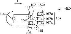
在图7中的浓度测量装置151将被描述。浓度测量装置151同样地包括一个类型判断电极152。如在图7中所示的,在浓度测量装置151中,正电极102和负电极103被排列在与在试片被插入的入口的设置方向I成直角的方向,以及一个第一类型判断电极152a、一个第二类型判断电极152b和一个第三类型判断电极152c被排列在比正的和负的电极102、103的位置靠里的测量装置151的内部。第一类型判断电极152a、第二类型判断电极152b和第三类型判断电极152c被统称为类型判断电极152。The concentration measuring device 151 in FIG. 7 will be described. The concentration measuring device 151 likewise includes a type judgment electrode 152 . As shown in FIG. 7, in the concentration measuring device 151, the
该正电极102被连接到该放大器105的输入。放大器105的输出通过A/D转换器107被连接到CPU153。该负电极103和第三类型判断电极152c两者都被接地。另一方面,第一类型判断电极152a和第二类型判断电极152b通过相对应的连接线路154、155被连接到CPU153,线路154、155通过各自的电阻器被正常地施加一个+5V的电压。The
CPU153如在下文中将描述的,只有当具有可由测量装置151测量的反应试剂的一个试片被设置到测量装置151中时,控制测量在液体检验样品中的成分的浓度。更具体地说,参照图10,当一个试片被设置到测量装置151中时,CPU153检测通过连接线路154、155获得的第一和第二类型判断电极152a、152b的各自的电势。只有在“适合的试片设置电势”的状态,其是当一个适当的试片被设置时获得的一个电势状态,即,第一类型判断电极152a的电势是一个高电平并且第二类型判断电极152b的电势是一个低电平,CPU153承认设置在测量装置151中的试片是具有可由该装置151测量的反应试剂的一个试片,并且开始测量在液体检验样品中的成分。如果第一和第二类型判断电极152a、152b不是上面的由适当的试片获得的电势状态,CPU153显示例如一个警告并且制止测量。The CPU 153 controls to measure the concentrations of components in the liquid test sample only when a test strip having a reaction reagent measurable by the measuring device 151 is set in the measuring device 151 as will be described hereinafter. More specifically, referring to FIG. 10, when a test strip is set into the measuring device 151, the CPU 153 detects respective potentials of the first and second
在该实施例,该CPU153被用于判断该类型判断电极152的电势。然而,本发明不限制为这种结构,只用于评价类型判断电极的电势的一个电势判断装置可以是在测量装置151之内分离地设置的。In this embodiment, the CPU 153 is used to judge the potential of the type judging electrode 152 . However, the present invention is not limited to this structure, and a potential judging means only for evaluating the potential of the type judging electrode may be provided separately within the measuring means 151 .
另外,类型判断电极的数量不再限制为3个。可以形成四个或者更多的类型判断电极以满足将被识别的试片类型的数量,在此情况下至少那些类型判断电极的电势的一个组合是适合于上面的适合试片设置电势。In addition, the number of type judgment electrodes is no longer limited to 3. Four or more type judging electrodes may be formed to satisfy the number of test strip types to be recognized, in which case at least one combination of potentials of those type judging electrodes is suitable for the above suitable test strip setting potential.
因此构成的浓度测量装置151的工作过程将被描述。图8和图9是将被设置到浓度测量装置151的试片161、165的简化的示意图。试片161、165基本上与图33和34的常规的试片1相同。图8和图9的标号162、166为前面所描述的反应试剂。在图中测量电极5和相反的电极6被反应试剂遮盖并没有示出。试片161是其上加有可由测量装置151测量的反应试剂的试片,而且即使试片165被设置到测量装置中,在液体测试样品中的成分也不可以由试片165测量。The operation of the thus constituted concentration measuring device 151 will be described. 8 and 9 are simplified schematic diagrams of the
当试片161被完全地插入到测量装置151中时,在试片161中形成的正极端子117和负极端子119将与测量装置151的正电极102和负电极103连接。此外,在试片161中形成一个第一类型判断端子163a,其将与测量装置151的第一类型判断电极152a连接。在试片161上设置的第二类型判断端子163b能与测量装置151的第二和第三类型判断电极152b和152c连接。第一类型判断端子163a和第二类型判断端子163b统称类型判断端子163。When the
在试片161被完全插入测量装置151的同时,测量装置151的第二和第三类型判断电极152b和152c被第二类型判断端子163b短路。因为第三类型判断电极152c被接地,所以第二类型判断电极152b的电势变为低电平。同时,虽然第一类型判断电极152a连接到试片161的第一类型判断端子163a,因为第一类型判断端子163a没有电连接,所以第一类型判断电极152a保持在+5伏。While the
此外,CPU153判断第一类型判断电极152a是高电平而第二类型判断电极152b是低电平,换句话说,满足适合的试片设置电平。CPU153认为被插入到测量装置151中的试片是配备有可由测量装置151测量的反应试剂的试片,从而开始在液体测试样品中的成分的测量。In addition, the CPU 153 judges that the first
试片165有正极端子117和负极端子119,类似于试片161。试片165还有一个第一个类型判断端子167a、一个第二类型判断端子167b和一个第三类型判断端子167c,当试片165完全地设置到测量装置151中时,它们可以分别与测量装置151的第一个类型判断电极152a、第二类型判断电极152b和第三类型判断电极152c电连接。这些第一、第二和第三类型判断端子167a、167b、167c是彼此独立的没有任何相互的电的连接。
当上面的结构的试片165被完全地插入到测量装置151中时,因为在试片165的第一、第二和第三类型判断端子167a、167b和167c之中没有相互的电的连接,该测量装置151的第一类型判断电极152a和第二类型判断电极152b的具有保持在+5V的状态。因此,该CPU153断定该第一和第二类型判断电极152a,152b两者在高电位,从而承认设置到该测量装置151中的该试片165不是具有可由该测量装置151测量的反应试剂的试片。在CPU153中不实施该成分的测量。When the
成分的浓度还可以在图7所示电路构成中测量。例如,血被滴到试片161的反应试剂162上,例如,在该血中葡萄糖的浓度通过测量装置151的正的和负的电极102和103测量。因为测量操作是基本上与第一实施例相同的,所以对其的描述将被省略。Concentrations of components can also be measured in the circuit configuration shown in FIG. 7 . For example, blood is dropped onto the
根据第三实施例,只有当具有可由测量装置151测量的反应试剂162的试片161被设置到测量装置151中,才允许成分测量。因此这样一个不慎的事故被防止,即,虽然葡萄糖是需要被测量的,但是一个用于乳酸测量的试片被不注意地设置到测量装置151中,并且获得一个错误的结果。According to the third embodiment, component measurement is allowed only when the
在上面的实施例中,虽然在试片中至少形成两个类型判断端子(163a和163b),但是端子数不限制于此。在四个或者更多类型判断电极提供于该测量装置中时,至少两个类型判断端子要被形成,以使电势判断装置可以从类型判断电极和类型判断端子的连接组合判断适当的试片设置电势。第四实施例In the above embodiment, although at least two type judgment terminals (163a and 163b) are formed in the test piece, the number of terminals is not limited thereto. When four or more type judging electrodes are provided in the measuring device, at least two type judging terminals are formed so that the potential judging means can judge an appropriate test piece setting from the connection combination of the type judging electrodes and the type judging terminals electric potential. Fourth embodiment
根据本发明第四实施例的一种浓度测量装置和用于该浓度测量装置的试片被显示在图11至15中。A concentration measuring device and a test strip used for the concentration measuring device according to a fourth embodiment of the present invention are shown in FIGS. 11 to 15 .
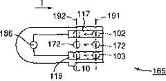
一种稍后将描述的CPU173作为在“发明的公开”中的变化判断装置的例子描述。下面将描述图11中的一种浓度测量装置。浓度测量装置171同样地装备有类型判断电极172,正如图11所示,正电极102、类型判断电极172和负电极103被排列在与设置方向I成直角的方向。正电极102被连接到放大器105的输入,输出放大器的输出通过A/D转换器107连接到CPU173。负电极103接地。该类型判断电极172通过一种连接线174被连接到该CPU173。一个+5V的电压通过一个电阻器正常地施加到该连接线174。A
CPU173以下列方式控制,以便只有当带有可由测量装置171测量的反应试剂的试片被设置到测量装置171中时,测量在液体检验样品中的分量。关于图14,在步骤(图14中由S指明的)21在一个试片被插入到测量装置171之后以及在步骤22中当该试片被完全地设置到装置171时,CPU173立即检测类型判断电极172的电势。在步骤23检测在两个时间点之间的电势的变化。更明确的地说,CPU173判断是不是电势的改变对应于一“适当的试片设置变化”,该“适当的试片设置变化”只有当带有可由测量装置171测量的反应试剂的一适当的试片被设置到测量装置171中时才会出现。当该电势变化是适当的试片设置变化时,CPU173承认带有可由测量装置171测量的反应试剂的试片被设置到测量装置171中,从而开始成分测量。当断定电势变化不是适当的试片设置变化时,CPU173作出一个警告显示,不开始该测量。The
在上面的实施例中,CPU173在上面的两个时间点检测类型判断电极172的电势藉此判断电势变化。然而,本发明不限制于本实施例,并且用于检测电势和判断电势变化的变化判断装置可以在测量装置171中分离地设置。In the above embodiment, the
浓度测量装置171的操作过程将被描述。要被设置到测量装置171中的并且是以简化的形式画出的图12和13中的试验元件181、185与图33和34的传统的试片1为基本上类似的结构。在图12和13中的参考数字182、186对应于反应试剂。设置的测量电极5和相反的电极6被反应试剂182、186遮避并且在图中看不见。试片181具有施加到其上的可由测量装置171测量的反应试剂,并且即使当试片185设置到测量装置171,试片185也不能测量液体检验样品中的成分。The operation procedure of the
在试片181中,与浓度测量装置171的正电极102和负电极103相对应,正极端子117和负极端子119沿着设置方向I扩展。而且,一个类型判断端子183被形成在试片181中,试片181在以设置方向I被插入到测量装置171中之后立即电地连接到浓度测量装置171的类型判断电极172。类型判断端子183是与负极端子119整体的形成的。In the test strip 181 , the
从图12中清楚的看出,在试片181沿着设置方向I对测量装置171的插入之后,测量装置171的正电极102、类型判断电极172和负电极103位于由参考数字191指定的一条线上,并且分别地电连接到正极端子117、类型判断端子183和负极端子119。因为试片181的类型判断端子183和负极端子119是集成的,所以在插入之后测量装置171的类型判断电极172和负电极103立即短路。因为负电极103被接地,所以测量装置171的类型判断电极172的电势变成地电平,就是低电位。As is clear from FIG. 12, after the test strip 181 is inserted into the measuring
当试片181在设置方向I被更进一步插入时并且完全地设置到测量装置171中时,测量装置171的正电极102、类型判断电极172和负电极103是呈现在一条线192上。在这个状态中,正电极102和负电极103被维护在电连接到正极端子117和负极端子119的状态。然而,因为在试片181上与类型判断电极172相当的位置处没有端子,所以测量装置171的类型判断电极172不被电连接。当试片被完全地设置时,测量装置171的类型判断电极172的电势被改变到+5V,即,高电位。When the test strip 181 is further inserted in the setting direction I and is completely set into the measuring
正如上面所描述的,当带有可由测量装置171测量的反应试剂182的试片181被设置到测量装置171中时,作为试片181的插入的结果,测量装置171的类型判断电极172的电势从最初的高电位变化到低电位,并且当该插入完成时再一次返回到高电位,即,产生较早提及的适当的试片设置变化。CPU173检测适当的试片设置变化,从而承认带有可由测量装置171测量的反应试剂182的试片181被设置到测量装置171,并且开始在液体检验样品中成分的测量。As described above, when the test strip 181 with the
顺便地,只有正极端子117和负极端子119被形成在试片185中,没有类型判断端子183。如图13所示,在试片185沿着设置方向I被插入到测量装置171之后,测量装置171的正电极102、类型判断电极172和负电极103位于线191上,致使正电极102和负电极103分别地电连接到正极端子117和负极端子119。因为试片185未装备有对应于类型判断电极172的一个端子,所以类型判断电极172没有电的连接。在该插入之后,类型判断电极172相应地保持在+5V。Incidentally, only the
当试片185被更进一步沿着设置方向I插入并且完全地设置到测量装置171中时,正电极102、类型判断电极172和负电极103是在线192上,正电极102和负电极103被保持在与正极端子117和负极端子119分别地电连接。因为在试片185中未形成与类型判断电极172对应的一个端子,所以测量装置171的类型判断电极172没有电的连接,并且保留+5V,即,甚至在完成插入后,是高电位。When the
当带有不能由测量装置171测量的反应试剂186的试片185被设置到测量装置171中时,测量装置171的类型判断电极172的电势不会从最初的高电位变化。因此,CPU173认定具有反应试剂186的试片185被设置到测量装置171中,并且不开始在液体检验样品中的成分的测量。When a
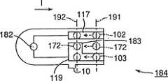
根据第四实施例,在测量装置171的类型判断电极172的适当的试片设置变化被适用于初始时表示高电位,在后来的试片的插入时为低电位,并且当插入完成时为高电位。电势变化不限制为这个模式,并且是由形成在试片中的与类型判断电极172相对应的类型判断端子的形状决定的。例如,在图15中的试片184可以被设计为以设定电势变化,即,适当的试片设置变化从当试片被插入时的高电位到当完成插入时的低电位。According to the fourth embodiment, an appropriate test strip setting change of the
成分浓度是以图11的电路结构测量的。例如,血被滴到试片181的反应试剂182上,并且通过测量装置171的正电极102和负电极103测量在该血液中的葡萄糖的浓度。由于上面的用于浓度测量的操作与第一实施例的描述基本上没有不同,所以它的描述被相应地省略。Component concentrations were measured with the circuit configuration of FIG. 11 . For example, blood is dropped onto the
根据该第四实施例,只有当有可由该测量装置171测量的反应试剂182的试片181被设置到测量装置171时,该成分能被测量。这样防止了一个不便,即,虽然需要测量葡萄糖,但是用于乳酸盐测量的一个试片被不注意地设置到测量装置171中并且获得一个错误的结果。According to the fourth embodiment, only when the test piece 181 having the
在前面的实施例中,各个浓度测量装置适合于识别与各个浓度测量装置相符的试片,这些试片在这些测量装置之中不能通用。例如,图2的试片115合适于图1的测量装置101,同样地,图5的试片141适合于图4的测量装置131。即使当图5的试片141被设置到测量装置101中,在测量装置101中也不能执行该成分的测量。同样地,即使图1的试片115被设置到测量装置131,该测量装置131不能执行该成分测量。由此,在这些实施例中,本发明可以实现一个生物传感器系统,它禁止在不同的浓度测量装置之中试片共享。In the foregoing embodiments, the respective concentration measuring devices are adapted to identify test strips corresponding to the respective concentration measuring devices, which cannot be used in common among the measuring devices. For example, the test strip 115 in FIG. 2 is suitable for the measurement device 101 in FIG. 1 , and similarly, the
图16是图1的浓度测量装置101的一个改变的例子。浓度测量装置201可以是由正电极102、负电极103和类型判断电极104按此顺序在与设置方向I成直角的方向设置构成的。能够在测量装置201中测量成分的一个试片205被显示在图17中。试片205具有用于电连接测量装置201的正电极102和类型判断电极104的一个第一端子206。而且,形成一个第二端子207,它电连接到测量装置201的负电极103。FIG. 16 is a modified example of the concentration measuring device 101 of FIG. 1 . The
即使当与测量装置101相符的试片被设置到测量装置201,也不可能进行该成分测量。而且,即使当与测量装置201匹配的试片205被设置到测量装置101,也不能测量该成分。那是因为正电极102和类型判断电极104在任何情况下不短路。如上所述,通过改变结构本发明可以提供生物传感器系统,在其中甚至在相同的实施例的测量装置之中试片也不能共享。Even when a test piece conforming to the measuring device 101 is set to the
基本上,在上面描述的各个实施例中的浓度测量装置能够测量一种成分,例如,葡萄糖,并且只有当带有适合葡萄糖测量的反应试剂被设置时,才适合执行葡萄糖浓度的测量。然而,在各个实施例中的上面的浓度测量装置和要在下面描述的根据第五实施例的浓度测量装置不限制于这个模式。例如,测量装置是可分的,当运输或者使用之前并可组合,以使它能测量许多种需要的成分,并且只有当与需要成分一致的试片被插入时,执行浓度测量。Basically, the concentration measuring device in each of the embodiments described above is capable of measuring one component, eg, glucose, and is suitable for performing glucose concentration measurement only when a reaction reagent suitable for glucose measurement is set. However, the above concentration measuring device in the respective embodiments and the concentration measuring device according to the fifth embodiment to be described below are not limited to this mode. For example, the measuring device is detachable before shipping or use and can be combined so that it can measure many kinds of required components, and only when a test strip corresponding to the required components is inserted, concentration measurement is performed.
在前面的描述中,类型判断电极和类型判断端子被用于检测是不是与要被测量装置检测的成分一致的试片被设置到该测量装置中。然而,使用类型判断电极和类型判断端子的技术的思想不是限制为上述实施例的概念,它是可利用的,例如,如在下列第五实施例中校准测量装置。在该测量装置中执行的校准至少包括通过在许多校准曲线之中一个需要的校准曲线的选择对成分浓度误差的补偿,以及当要显示预定浓度值的预先调整的试片被设置到该测量装置中时,基于一个预定浓度值显示检验测量装置的操作。第五实施例例示上面的校准曲线的选择。第五实施例In the foregoing description, the type judging electrodes and the type judging terminals are used to detect whether or not a test piece consistent with the composition to be detected by the measuring device is set into the measuring device. However, the idea of the technique using the type judging electrodes and the type judging terminals is not limited to the concepts of the above-described embodiments, and it is available, for example, to calibrate the measuring device as in the following fifth embodiment. Calibration performed in the measuring device includes at least compensation for component concentration errors by selection of a desired calibration curve among a plurality of calibration curves, and when a pre-adjusted test strip to display a predetermined concentration value is set to the measuring device When in the middle, the display verifies the operation of the measurement device based on a predetermined concentration value. The fifth embodiment exemplifies selection of the above calibration curve. fifth embodiment
正如在“实现本发明的最佳方式”的开始描述的,包括在施加在与要被检测的成分相应的试片的基底材料上的反应试剂中的酶对于每个生产批量有一个生产误差。例如,当包含100mg/dl浓度的葡萄糖的一种液体检验样品被滴到包括第一生产批量的酶上时,测量装置显示100mg/dl。另一方面,当相同的液体检验样品被滴到包括第二生产批量的酶的一种反应试剂上时,测量装置显示90mg/dl。由于该酶本身的生产误差,如上所述在检测的值中包括一误差。虽然在检测的值中引起最大的误差的一个因素是酶的制造误差,但是形成在试片的底部材料上的正极端子、负极端子等的电阻值也同样招致误差,这是因为被印刷以便形成端子的传导性的碳糊也不是无制造误差的。As described at the beginning of "Best Mode for Carrying Out the Invention", the enzyme included in the reaction reagent applied on the base material of the test piece corresponding to the component to be detected has a production error for each production lot. For example, when a liquid test sample containing glucose at a concentration of 100 mg/dl is dropped onto the enzyme comprising the first production batch, the measuring device indicates 100 mg/dl. On the other hand, when the same liquid test sample was dropped onto a reaction reagent including the enzyme of the second production lot, the measuring device showed 90 mg/dl. Due to the production error of the enzyme itself, an error is included in the detected value as described above. Although one factor that causes the largest error in the detected value is the manufacturing error of the enzyme, the resistance value of the positive terminal, negative terminal, etc. formed on the bottom material of the test piece also causes errors because it is printed to form The conductive carbon paste of the terminals is also not free from manufacturing errors.
为了消除上面的问题,照惯例,用于补偿在检测的浓度中的误差从而显示一个真实的浓度的校准曲线信息被预先储存在测量装置中,正如在日本的专利的出版物4-357452中所揭示的。以及,为每一组具有相同的生产批量的试片准备一个用于从许多校准曲线信息中选择可以补偿每个生产批量的制造误差的校准曲线信息的校准试片。因为对于测量的大有影响的因素是酶的制造误差,相同的生产批量通常对应于一组试片,该组试片被施加包括相同的生产误差的酶的反应试剂。照惯例,使用不同的生产批量的试片的一个用户首先设置校准试片到测量装置,然后选择与使用的试片的生产批量一致的校准曲线信息。只要使用的试片是相同的生产批量的试片,选择一次校准曲线信息是足够的,而不必要在相同的生产批量的各个试片被使用时每次都选择该信息。In order to eliminate the above problems, conventionally, calibration curve information for compensating for errors in detected concentrations so as to show a true concentration is stored in the measuring device in advance, as disclosed in Japanese Patent Publication No. 4-357452 revealed. And, a calibration test piece for selecting calibration curve information capable of compensating for a manufacturing error for each production lot is prepared for each group of test pieces having the same production lot. Since the most influential factor for the measurement is the production error of the enzyme, the same production lot usually corresponds to a group of test strips which are applied with the reaction reagent of the enzyme including the same production error. Conventionally, a user who uses test strips of different production lots first sets calibration test strips to the measuring device, and then selects calibration curve information consistent with the production lot of the test strips used. As long as the test pieces used are test pieces of the same production lot, it is sufficient to select the calibration curve information once, and it is not necessary to select the information every time each test piece of the same production lot is used.
正如在前面所描述的,在传统的浓度测量装置中,用户需要关注试片的酶的变化,就是,生产批量的变化。除非与酶的生产误差一致的校准曲线信息被选择,否则在测量装置显示的检测的值中包含大的误差。As described above, in the conventional concentration measuring device, the user needs to pay attention to the variation of the enzyme of the test piece, that is, the variation of the production lot. Unless calibration curve information consistent with production errors of the enzyme is selected, large errors are contained in the detected values displayed by the measuring device.
第五实施例是被设计为要解决该问题,在其中选择校准曲线信息的功能是根据前面的实施例描述的类型判断电极和类型判断端子的使用的技术的概念,由类型判断电极、类型判断端子和CPU进行的。The fifth embodiment is designed to solve this problem, wherein the function of selecting the calibration curve information is based on the concept of the technology of the use of the type judgment electrode and the type judgment terminal described in the previous embodiment, by the type judgment electrode, the type judgment terminal and CPU.
正如将在前面描述的,被构成的第五实施例将是第四实施例的一个修改,这是因为将被检测的每个成分通常有十种或者更多种类校准曲线信息,因此必需使试片的类型判断端子用尽可能少的类型判断端子数量区别十种或者更多种类的校准曲线信息。然而,不只是通过第四实施例改变结构能使校准曲线信息的选择有效,而且如果将被区分的校准曲线信息仅仅包含几种,那么上面的第二或者第三实施例的修改在某些情况下可以处理该选择。As will be described earlier, the fifth embodiment constructed will be a modification of the fourth embodiment, because each component to be detected usually has ten or more kinds of calibration curve information, so it is necessary to make the test The type judgment terminal of the sheet distinguishes ten or more kinds of calibration curve information with as few type judgment terminals as possible. However, not only changing the structure by the fourth embodiment can make the selection of the calibration curve information effective, but also if the calibration curve information to be distinguished contains only several kinds, the modification of the second or third embodiment above may in some cases The selection can be handled below.
第五实施例是如此构成以至通过形成在试片上的类型判断端子选择校准曲线信息,同时,测量装置的类型判断电极和CPU判断可测量的成分,类似于第一至第四实施例。第五实施例不限制于这个结构,可以是适合于只是选择校准曲线信息。The fifth embodiment is so constituted that the calibration curve information is selected by the type judgment terminal formed on the test strip, while the type judgment electrodes and CPU of the measuring device judge measurable components, similarly to the first to fourth embodiments. The fifth embodiment is not limited to this structure, and may be adapted to select only calibration curve information.
根据本发明第五实施例的一种浓度测量装置和用于该浓度测量装置的试片将参照图19至24被描述。在下文将被描述的CPU258、308和358是发挥“变化判断装置”功能的实施例。A concentration measuring device and a test strip used for the concentration measuring device according to a fifth embodiment of the present invention will be described with reference to FIGS. 19 to 24 . The
图19显示第五实施例的一例子的浓度测量装置251,图20是将被设置到该浓度测量装置251中的一个试片271。FIG. 19 shows a
浓度测量装置251对应于关于图11的第四实施例的浓度测量装置171的一个修改,具有在与试片271的设置I成直角的方向设置的正电极102、三个类型判断电极252、253和254,以及负电极103。正电极102被连接到放大器105的输入,输出放大器的输出通过A/D转换器107连接到CPU258。负电极103接地。类型判断电极252-254通过各自的连接线255-257连接到CPU258。通常,每个+5V的电压通过电阻器被施加到每一连接线255-257。The
CPU258配备有一个储存部分259,储存用于补偿包括在液体检验样品中的特定的成分的浓度中的测量误差的多条校准曲线信息。类似于上面的各个实施例描述的测量装置,只有当带有可由浓度测量装置251测量的反应试剂的试片271被设置到测量装置251中时,CPU258实现控制以测量该浓度,以及按照插入测量装置251中的试片271的生产批量从储存部分259中选择和提取可以补偿测量误差的一个预定校准曲线信息。虽然CPU258的操作将稍后详细地讨论,基本上,在试片271被开始在设置方向I插入以测量装置251之后及试片271被完全地设置到251中之前,CPU258检测在类型判断电极252、253和254中的每一个上的电势变化模式,即,正如在第四实施例中描述的适当的试片设置变化,并且也检测将稍后描述的“校准曲线信息选择变化”。基于检测的适当的试片设置变化,CPU258判断是不是具有与该可由测量装置251测量的特定的成分起反应的反应试剂的试片被设置到该装置251。此外,基于该检测的校准曲线信息选择变化,CPU258选择一个校准曲线信息,通过该校准曲线信息按照该设置试片的在检测的浓度中的误差可以被校准。The
类型判断电极252-254可以被分为第一电极和第二电极。在试片开始被插入之后及试片被完全地插入测量装置之前,第一电极产生从高电位到低电位以及从低电位到高电位的适当的试片设置变化,并且产生校准曲线信息选择变化。在第五实施例中,类型判断电极252和253作为第一电极。在本实施例中低电位电势对应于接地电位,高电位电势对应于+5V。第二电极与在第一电极的电势变化同步交替地产生高和低电位电势,以便于检测第一电极的适当的试片设置变化和校准曲线信息选择变化的定时。类型判断电极254对应于在第五实施例中的第二电极。The type judgment electrodes 252-254 may be divided into first electrodes and second electrodes. After the test strip is initially inserted and before the test strip is fully inserted into the measuring device, the first electrode produces the appropriate test strip setting changes from high potential to low potential and from low potential to high potential, and generates calibration curve information selection changes . In the fifth embodiment, the
虽然在第五实施例中,第一电极包含两个电极,但是第一电极的电极数量不特定的限制于此。Although in the fifth embodiment, the first electrode includes two electrodes, the number of electrodes of the first electrode is not particularly limited thereto.
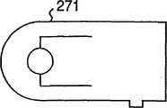
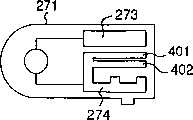
图20的试片271基本上是构成为与图33和34中显示的传统的试片1类似的结构。参考数字272对应于反应试剂,在图中它遮避了测量电极5和相反的电极6。可由测量装置251测量的反应试剂被应用到试片271。The
试片271具有在设置方向I扩展的将分别地电连接到测量装置251的正电极102和负电极103的一个正极端子273和一个负极端子274。在试片271开始被插入到测量装置251之后及被完全地设置到测量装置251中之前,在试片271在I方向移动的同时,在正电极102和正极端子273之间和在负电极103和负极端子274之间的电的连接被维持。试片271更进一步配备有与测量装置251的类型判断电极252、253和254一致的类型判断端子275、276和277。构成类型判断端子275的两个类型判断端子275-1和275-2被间断地形成在类型判断电极252的通路上,构成类型判断端子276的四个类型判断端子276-1至276-4被间断地形成在类型判断电极253的通路上,如此以致于在试片271沿着方向I开始被插入到测量装置251之后及最后设置到测量装置251之前的时候,造成类型对判断电极252和253的合适试片设置变化和校准曲线信息选择变化。类型判断端子275和276对应于用于对于第一电极产生电势变化的一个部分。类型判断端子275-1和275-2,以及类型判断端子276-1至276-4通过连接线被连接到负极端子274。连接线是与类型判断电极252-254电绝缘的,以致防止在类型判断电极252-254和随类型判断电极252-254移动的连接线路之间的电的连接。The
在试片271沿着方向I开始被插入到测量装置251之后及完全地设置到测量装置251之前的时候,为了产生对判断电极254的合适试片设置变化和校准曲线信息选择变化,构成类型判断端子277的两个类型判断端子277-1和277-2被间断地形成在类型判断电极254的通路上,类型判断端子277对应于用于为第二电极产生定时的一个部分。在本实施例中,类型判断端子277-1和277-2是与负极端子274整体的形成的。When the
同时,一个设置完成检测端子278与负极端子274整体的形成在试片271中,以使测量装置251检测试片271何时被完全地设置到装置251中。Meanwhile, a setting
上面描述的正端子273、负极端子274、类型判断端子275-277和设置完成检测端子278是通过印制导电性的材料等等形成的,类似于已有技术。稍后将更详细地描述端子的形成方法。The above-described positive terminal 273,
虽然根据第五实施例提供了六个类型判断端子275和276作为对第一电极的电势变化的部分,但是类型判断端子的数量不被限制于此,并且可以是由将被选择的校准曲线信息的种类数量确定的。Although according to the fifth embodiment six
如上面的构成的浓度测量装置251以下列方式操作。The
在图20中,在紧随试片271以设置方向I被插入到测量装置251之后的那一时间点,测量装置251的正电极102、类型判断电极252-254和负电极103被放置在由行281所示的位置。正电极102被电连接到试片271的正极端子273,类型判断电极253和254分别地电连接到类型判断端子276-1和277-1,负电极103电连接到负极端子274,而没有相应端子的类型判断电极252没有电的连接。类型判断端子275-1和275-2,以及类型判断端子276-1至276-4电连接到负极端子274,类型判断端子277-1和277-2是与负极端子274整体的形成的。结果,接地负电极103电连接到负极端子274,那么类型判断端子275-1、275-2、276-1至276-4和277-1、277-2通过负极端子274变成低电位电势,就是,在本实施例中的接地电势。在试片被开始插入的时间点281,类型判断电极253、254和负电极103是接地电势,即,低电位电势,而连接到类型判断电极253、254的连接线256、257是接地电势,而连接到类型判断电极252的连接线255是+5V,即,该高电位电势。In FIG. 20, at the point of time immediately after the
根据试片271沿着设置方向I对测量装置251的更进一步的插入,当正电极102、类型判断电极252、253、254和负电极103出现在由线282所示的位置时,正电极102保持与正极端子273的连接,负电极103也保持与负极端子274的连接,而类型判断电极252、253分别地电连接到类型判断端子275-1、275-2。同时,类型判断电极254没有相对应的端子,因此没有电连接。因此,在位置282,类型判断电极252和253以及负电极103是接地电势,连接到类型判断电极252的连接线255和连接线256是接地电势,连接到类型判断电极254的连接线257是+5V,即,高电位电势。According to the further insertion of the
同样地,当试片271在设置方向I对测量装置251的更进一步的插入时,正电极102、类型判断电极252-254和负电极103出现在由线283所示的位置上,正电极102保持与正极端子273的连接状态,同样地,负电极103保持与负极端子274的连接,连接线255导致高电位电势而连接线256和257改变到接地电势。其后,当试验271在设置方向I对测量装置251的更进一步的插入时,导致将正电极102、类型判断电极252-254和负电极103定位在由线284所示的位置上,正电极102保持与正极端子273的连接状态,负电极103仍然与负极端子274连接,连接线255和256变为接地电势而连接线257改变到高电位电势。当试片271被最后设置到测量装置251中时,正电极102、类型判断电极252-254和负电极103出现在线285所示的一个位置,正电极102与正极端子273的和负电极103与负极端子274的各个连接状态被保持,连接线255-257全部被变成接地电势。Likewise, when the
根据试片271被开始设置之后及试片271被完全地设置到测量装置251中之前试片271的移动,换言之,根据正电极102、类型判断电极252-254,以及负电极103从位置281到位置285的移动,测量装置251的CPU258检测在类型判断电极252-254,即,连接线255-257的电势变化。更明确的说,当试片271被完全地设置到测量装置251中,以及当CPU258检测每一连接线255-257达到接地电势时,CPU258断定试片271被插入到测量装置251的一个设置完成位置。根据试片271从一个开始位置到完成位置的移动,连接线257的变化是从接地电势-->高电位电势-->接地电势-->高电位电势-->接地电势。换句话说,在连接线257上接地电势和高电位电势被交替重复的。CPU258检测在连接线257上的交替的电势变化。基于交替的电势变化,CPU258获得适当的试片设置变化的一个检测定时,该适当的试片设置变化是在连接线255、256上的电势变化,并且也检查试片271是不是被正常地设置到测量装置251。即,只有在试片271的开始位置之后到设置完成位置连接线257两次变成高电位电势时,CPU258断定试片271被正常地设置到测量装置251。在上面的情况之外的其他情况下,CPU258断定试片271在与设置方向I相反的方向至少移动一次,换句话说,试片271返回,例如表现一误差显示。According to the movement of the
与连接线257的电势变化同步,CPU258检测在连接线255、256上产生的适当的试片设置变化。更明确的说,在第五实施例中,当试片271从设置开始到设置完成被正常地设置到测量装置251中时,连接线255的变化是从高电位电势-->接地电势-->高电位电势-->接地电势,由高电位电势变到接地电势,并且连接线256是从接地电势-->接地电势-->接地电势-->接地电势到接地电势变化的。CPU258识别在每一连接线255和256的电势变化模式,同时类型判断电极252、253被移动以定位从位置281至284。在本实施例中,因为在位置281至284有六个类型判断端子275、276,电势变化可以是26,即最大值64个模式。电势变化的64个模式对应于校准曲线信息,以及在本实施例更进一步对应于可由设置试片271测量的被储存在储存部分259中的特定的成分的信息。在第五实施例中,根据在类型判断端子252、253定位于设置完成位置285之前那一刻的连接线255、256的每一电势,在位置284,CPU258选择特定的成分的信息,即,用于试片的类型认证的信息,以及根据“校准曲线信息选择变化”选择校准曲线信息。“校准曲线信息选择变化”是在类型判断端子252、253从位置281到283移动时连接线255、256的电势变化。相应地,在第五实施例中,存在有用于选择校准曲线信息的校准曲线信息选择变化的24=16个模式,以及用于选择特定的成分的信息的电势变化的22=4个模式。Synchronously with the potential change of the connecting
基于识别出的电势变化,CPU258从储存部分259中选择并取出与设置试片271的生产批量一致的校准曲线信息以及可由试片271测量的特定的成分的信息。Based on the identified potential change, the
当试片271被设置到浓度测量装置251中时,基于表示特定的成分的被选择的信息、用于标识试片的类型的信息,如果CPU258决定与可由测量装置251测量的特定的成分一致的试片271被设置,那么CPU258变成了一个可测量的状态。然后CPU258选择和提取与试片271的生产批量一致的校准曲线信息。例如,当血被滴在设置试片271的反应试剂上时,在血中的葡萄糖的浓度是通过测量装置251的正电极102和负电极103检测的。CPU258利用在选择的校准曲线信息校准在进行特定的成分的浓度测量中的浓度,并且使得结果被显示。因为本浓度测量操作是基本上类似于第一实施例描述的方式实现的,所以在这里将相关的描述省略。When the
在对比中,如果设置了一个对应于不可由测量装置251测量的特定的成分的试片,那么CPU258不会变成可测量的状态,并且显示一错误显示。In contrast, if a test piece corresponding to a specific component not measurable by the measuring
在上面描述的第五实施例中,只有当具有可由测量装置251测量的反应试剂的试片271被设置到测量装置251中时,可以执行该测量。因此,这样可以防止一个不便,即,虽然需要测量葡萄糖,但是用于乳酸盐测量的一个试片被不注意地设置到测量装置171中并且获得一个错误的结果。此外,当用于特定成分的试片271被设置时,可以利用与该试片271的生产批量一致的校准曲线信息校准浓度,从而使得用户不必要注意试片的生产批量和设置校准试片以选择校准曲线信息。因此,当一个正确的试片,即,具有可由一个测量装置测量的反应试剂的一个试片被设置,可以没有校准的获得该成分的浓度。用户相应地免除了使用校准试片和测量试片两者的传统的麻烦,于是从烦恼中解放出来。In the fifth embodiment described above, only when the
根据第五实施例,正如前面所描述的,为在连接线255、256上的电势变化的适当的试片设置变化模式通常是两个种类,用于校准曲线信息选择变化的电势变化模式和用于选择表示特定的成分的信息的电势变化模式。然而,本发明不限制于此。例如,在可由测量装置测量的特定的成分已经知道以及与特定的成分一致的试片在被设置的情况下,不需要用于选择特定的成分的信息的电势变化模式,因此,在适当的试片设置变化中的模式可以完全地利用校准曲线信息选择变化的模式。相反地,其他种类的电势变化可以被加到上面的模式中以形成三种或者更多种类的模式。According to the fifth embodiment, as described above, the appropriate test strip setting change pattern for the potential change on the
浓度测量装置和试片不被限制为在图19和20中显示的实施例,例如,可以被改变成在图21至24中显示的将在下面描述的形式。The concentration measuring device and the test strip are not limited to the embodiments shown in FIGS. 19 and 20 , for example, may be changed to the forms shown in FIGS. 21 to 24 to be described below.
在上面的浓度测量装置251中两个连接线255、256的电势变化被用于选择校准曲线信息和特定的成分信息。另一方面,根据图21的浓度测量装置301,在连接到三个类型判断电极302-304的三个连接线305-307之中的一个连接线306的电势变化被CPU308检测到,此检测的信息至少被用于校准曲线信息的选择。连接线305、307两者通过各自的10k欧姆电阻器被连接到各个+5V电源,连接线306通过一个100k欧姆电阻器接地。在其他点上测量装置301的结构与上述的测量装置251的结构相同。In the upper
与将被设置到测量装置301中的试片321上端子的形成有关基本原理是与试验271的形成相类似的。然而,虽然试片271具有与类型判断电极252和253一致的分开的类型判断端子275和276,差别是试片321装备有将类型判断电极302和303对应的一个类型判断端子325。因为一个类型判断端子325是与类型判断电极302和303相对应的提供的,所以类型判断端子325是适合于被放在沿着设置方向I的六个点上,以致获得上面的适当的试片设置变化的64个模式,这类似于该测量装置251。不用说,类型判断端子325的数量不被限制为上面的六个点,并且可以根据适当的试片设置变化的模式的数量确定。The basic principles related to the formation of the terminals on the
下面将描述上面的结构的测量装置301的操作过程。The operation of the measuring
在试片321开始被设置到测量装置301的起始时间点,正电极102、三个别类型判断电极302-304和负电极103位于由线331显示的位置。正电极102被电连接到试片321的正极端子323,类型判断电极302、303电连接到类型判断端子325,类型判断电极304电连接到类型判断端子327,负电极103电连接到负极端子324。类似于试片271的类型判断端子277,试片321的类型判断端子327产生定时。根据试片321在设置方向I的移动,类型判断端子327产生对连接到类型判断电极304的连接线307的接地电势和高电位电势的交替的电势变化。在测量装置301中,在试片321的设置开始到完成之后,当连接线307三次变成高电位电势时,CPU308断定试片321是完全正常地设置到测量装置301中,并且在除了上述情况之外的其它情况下显示一错误显示。At the initial point in time when the
当类型判断电极302和303是由类型判断端子325电连接时,电源电压通过10千欧姆电阻器和连接线305被施加到与类型判断电极303连接的连接线306,以使连接线306变成高电位电势。当试片321更进一步在设置方向I移动时,以及如果类型判断端子325不在的话,例如,当类型判断电极302和303位于由线333表示一个位置时,类型判断电极302和303彼此并不电连接。在这种情况下,连接线306通过100千欧姆电阻器接地并因此变成低电位电势。在目前的例子中,根据试片321从开始位置到在那里有正电极102的一个设置完成位置的移动,三个类型判断电极302-304和负电极103是在一条线337上,连接线306显示出从高电位电势-->高电位电势-->低电位电势-->高电位电势-->高电位电势-->高电位电势到低电位电势的变化。取决于类型判断端子325的存在/不存在,在试片321从开始位置移动到设置完成位置的同时,可以引起对连接线306的电势变化上升。CPU308检测在连接线306的电势变化模式,然后选择并提取例如预先储存在与连接线306的电势变化模式相对应的一个储存部分309中的校准曲线信息。在其它点上测量装置301是与测量装置251的相同方式操作的,因此在这里省略对它们的描述。When the
参照图23,在浓度测量装置351中,在连接线356的电势变化被检测,这类似于测量装置301,从而选择例如校准曲线信息。用于产生到连接线356的电势变化的结构与测量装置251相比是不同的。具体地说,测量装置351具有三个类型判断电极352-354,连接到类型判断电极352-354的连接线355-357,一个CPU358以及一个储存校准曲线信息等的一个储存部分359。各个+5V电源经由各自的电阻器连接到连接线355-357。测量装置351另外备有一个接地电极360,其与产生由CPU358检测的电势变化的连接线356的类型判断电极相邻。当CPU358检测类型判断电极352电连接到将稍后描述的一个设置完成检测端子378时,CPU358识别出对装置351的一个试片371的设置完成。Referring to FIG. 23, in the
在此期间,将被设置到测量装置351的试片371类似于试片321,其具有正极端子323、负极端子324以及类型判断端子375等。试片371还包括与负极端子324整体的形成的设置完成检测端子378。设置完成检测端子378检测何时试片371被完全地设置到测量装置351中。当类型判断电极352位于由387表示的设置完成位置时,检测端子378将形成电连接到类型判断电极352的结构。在其他方面试片371的结构是与试片321的结构相同的。During this time, the
在下文将描述如此构成的测量装置351的操作。因为该操作与测量装置301的操作基本上是类似的,将仅仅描述装置351和装置301之间的差别。The operation of the measuring
即,当试片371开始被设置到测量装置351时,类型判断电极353和接地电极360位于由线381表明的位置并且电连接到类型判断端子375。因为类型判断电极353的电连接是通过类型判断端子375电连接到接地电极360,所以由CPU358检测的连接线356的电势变化变成接地电势。当试片371被更进一步在设置方向I插入并且类型判断电极353和接地电极360位于由线383表明的位置时,由于试片371没有类型判断端子,所以连接线356变成+5V的高电位电势。That is, when the
根据前面描述的实施例,利用在试片371被开始插入之后及正电极102、三个类型判断电极352-354、接地360以及负电极103达到线387表示的位置之前试片371的移动,连接线356显示出电势变化是从接地电势-->接地电势-->高电位电势-->接地电势-->接地电势-->接地电势到该接地电势。因此,基于类型判断端子375的存在/不存在,根据在设置开始到完成之后的试片371的移动,连接线356经历电势变化。CPU358检测在连接线356的电势变化模式,然后选择并提取例如预先储存在与连接线356的电势变化模式相对应的一个储存部分359中的校准曲线信息。在其它点上测量装置351是与较早描述的测量装置251以相同方式操作的,因此在这里省略对它们的描述。According to the previously described embodiment, using the movement of the
在下面将说明用于正极端子、类型判断端子、负极端子以及形成在第五实施例的试片中的设置完成检测端子的一种方法,尤其是,用于形成类型判断端子的一种方法。A method for the positive terminal, the type judgment terminal, the negative terminal, and the setting completion detection terminal formed in the test piece of the fifth embodiment, in particular, a method for forming the type judgment terminal will be described below.
正如以前描述的,试片不可避免地包括对于每一生产批量的测量误差,并且对于测量误差影响大的因素是在反应试剂中酶的生产误差。因此,用于形成将在下文描述的判断元件方法是一种基于酶的生产误差形成判断元件的方法。试片271作为下列描述中的一个例子,下列描述是关于到试片的类型判断端子275-277形成校准曲线信息选择模式的一种情况。As described before, test strips inevitably include measurement errors for each production lot, and a factor having a large influence on measurement errors is the production error of enzymes in reaction reagents. Therefore, a method for forming a judgment element to be described below is a method for forming a judgment element based on production errors of enzymes. The
通常有两个方法用于形成正极端子、类型判断端子等等。根据第一个方法,在反应试剂的生产误差,尤其是酶的生产误差被确认之后,形成类型判断端子,以致至少造成对连接线的校准曲线信息选择变化。根据第二方法,尤其是在酶的生产误差被确认之后,预先沿着设置方向I形成没有模式图案的一个类型判断端子,并且在该没有模式图案的类型判断端子上施加绝缘物质,所以至少造成对该连接线路的校准曲线信息选择变化。Generally, there are two methods for forming the positive terminal, the type judgment terminal, and the like. According to the first method, after the production error of the reaction reagent, especially the production error of the enzyme is confirmed, the type judgment terminal is formed so as to cause at least a selection change of the calibration curve information of the connecting line. According to the second method, especially after the production error of the enzyme is confirmed, a type judgment terminal without a pattern pattern is formed in advance along the installation direction I, and an insulating substance is applied to the type judgment terminal without a pattern pattern, so that at least Select Change for the calibration curve information for this connection.
下面将参照图25至28描述上述的第一个方法。正如图25所示,25,测量电极、相反的电极以及连接到这些电极的连接线被形成在样品试片271的基底材料上,以确定校准曲线信息。除了测量电极和相反的电极的一部分之外,利用绝缘糊等形成一绝缘层,正如在图26中由倾斜线指出的,并且其后反应试剂272被施加在测量电极和相反的电极上。在图26-28中的倾斜线不是表示横截面的阴影。那么,在图27中,包含与反应试剂272起反应并且它的浓度是已知的一种特定的成分的一种规格的溶液被滴到该反应试剂272上,并且一个电压被施加到反应试剂272的一部分上。那么一个浓度,一个电流值被测量。根据检测的浓度和知道的浓度,获得该反应试剂272的测量误差。在图28中,类型判断端子275、276和正极端子273等等是由导电材料形成的,以使与对于上面的测量错误的校准曲线信息补偿一致的校准曲线信息选择变化利用类型判断端子275、276和正极端子273等引出。The above-mentioned first method will be described below with reference to FIGS. 25 to 28. FIG. As shown in FIG. 25, 25, measurement electrodes, opposite electrodes, and connection lines connected to these electrodes are formed on the base material of the
在前面的描述中,试片是用于确定校准曲线信息的样品。在为了出售的其中包括与施加到样品元件的反应试剂的酶相同的生产批量的酶的试片271被应用的情况中,应该根据在该基底材料上反应试剂的应用时间测定,选择形成判断端子275的一种传导性的材料。即,通常,包括在反应试剂272中的酶被稍微加热而酶的活力被减少,或者一旦不比50摄氏度低的一个温度作用到酶上,酶变成非活性的。因此试片271是不可用的。因此,在与生产批量一致的校准曲线信息被确定之后产生试片271的情况中,以及如果在类型判断端子275等被形成之前反应试剂272被施加在基底材料上,一种在标准温度处理的传导性的材料应该用于该类型判断端子275等,正如图28所示。例如,上面的类型的传导性的材料是包含银和环氧基树脂粘合剂的的导电的粘合剂比如“ELECTRODAG5820”(Acheson(日本)公司商品名)或者包含镍和热塑性的粘合剂比如“SS24306”(Acheson(日本)公司商品名),等等。In the foregoing description, a test strip is a sample used to determine calibration curve information. In the case where the
同时,在类型判断端子275等等被形成之后当反应试剂272被施加在基底材料上时,上面描述的适于正常温度类型的导电的材料不是必需的,而可以使用照惯例需要在大致130-150摄氏度加热使用的热硬化性的导电的材料。Meanwhile, when the
第二方法将参照图29-32描述。The second method will be described with reference to Figures 29-32.
在图29中,在用于确定校准曲线信息的样品试片271的基底材料上形成测量电极、相反的电极、连接到这些电极的连接线、正极端子273、负极端子274、设置完成检测端子278以及没有模式的类型判断端子401、402。类似于参照图26的描述,在形成除了测量电极和相反的电极的部分之外的一绝缘层之后,施加反应试剂272,正如在图30中倾斜线所显示。在图30-32中的倾斜线不是用于表示横截面的阴影。在图31,标准溶液被滴到反应试剂272,以及一个电压通过正极端子273以及负极端子274施加到部分反应试剂272上。然后,检测标准溶液的浓度、电流。根据检测的浓度和知道的浓度,获得反应试剂272的测量误差。在图32,绝缘糊405、406等被如倾斜线指出的施加在没有模式的类型判断端子401、402上,以使能够补偿上面的测量误差的校准曲线信息可以被选择,从而形成用于选择该校准曲线信息的一个模式并且获得类型判断端子275、276。作为为了选择校准曲线信息对没有模式的类型判断端子401、402形成图形模式的方法,一对类型判断端子401、402进行切割或类似的处理,代替在常温下进行的施加绝缘糊405、406。例如,上面的类型的绝缘糊405、406是包含聚亚安酯PV序列树脂粘合剂的绝缘颜料,正如“JEF-226C”(Acheson(日本)有限公司商品名))或者包含聚酯树脂粘合剂的绝缘颜料比如“JEH-116G”(Acheson(日本)有限公司商品名)的绝缘颜料等等。In FIG. 29 , on the base material of a
正如较早地提到的,根据施加到试片271的反应试剂272的应用时间,热硬化性类型的绝缘糊能被使用。As mentioned earlier, depending on the application time of the
根据上面的第二方法,如图31,当标准溶液的浓度被检测时,因为正极端子273和负极端子274被使用,该浓度可以利用作为正极端子273和负极端子274包括的材料的导电的碳糊的产品误差被检测,和第一个方法不同。因此,特定的成分的浓度可以用比第一个方法更高的准确性检测。According to the second method above, as shown in FIG. 31, when the concentration of the standard solution is detected, since the
在1997年7月22递交的日本专利申请No.9-195866的内容包括说明书、权利要求书、附图、以及摘要被合并在此处被引用。The contents of Japanese Patent Application No. 9-195866 filed on July 22, 1997 including specification, claims, drawings, and abstract are incorporated herein by reference.
虽然本发明已经参照附图结合优选的实施例被完全地描述,显然的对于本领域的熟练者来说是能够做出改变和修改的。这样的变化和修改只要没有脱离由权利要求所定义的本发明的范围,将被认为是在本发明的范围内。Although the present invention has been fully described with reference to the accompanying drawings and preferred embodiments, it will be apparent that changes and modifications will occur to those skilled in the art. Such changes and modifications are to be considered within the scope of the present invention as long as they do not depart from the scope of the present invention defined by the claims.
Claims (32)
Translated fromChineseApplications Claiming Priority (2)
| Application Number | Priority Date | Filing Date | Title |
|---|---|---|---|
| JP195866/1997 | 1997-07-22 | ||
| JP19586697 | 1997-07-22 |
Publications (2)
| Publication Number | Publication Date |
|---|---|
| CN1265194A CN1265194A (en) | 2000-08-30 |
| CN1129792Ctrue CN1129792C (en) | 2003-12-03 |
Family
ID=16348300
Family Applications (1)
| Application Number | Title | Priority Date | Filing Date |
|---|---|---|---|
| CN98807506AExpired - LifetimeCN1129792C (en) | 1997-07-22 | 1998-07-15 | Densitometer, test piece for densitometer, biosensor system, and method for forming terminal of test piece |
Country Status (16)
| Country | Link |
|---|---|
| US (2) | US6599406B1 (en) |
| EP (5) | EP2056108A1 (en) |
| JP (1) | JP3859239B2 (en) |
| KR (1) | KR100675463B1 (en) |
| CN (1) | CN1129792C (en) |
| AT (1) | ATE427483T1 (en) |
| AU (1) | AU725457B2 (en) |
| BR (2) | BR9810794B1 (en) |
| CA (1) | CA2296608C (en) |
| DE (1) | DE69840703D1 (en) |
| EA (1) | EA002856B1 (en) |
| ES (1) | ES2323393T3 (en) |
| NZ (1) | NZ502011A (en) |
| PT (1) | PT1024358E (en) |
| TR (1) | TR200000200T2 (en) |
| WO (1) | WO1999005516A1 (en) |
Families Citing this family (188)
| Publication number | Priority date | Publication date | Assignee | Title |
|---|---|---|---|---|
| US6036924A (en) | 1997-12-04 | 2000-03-14 | Hewlett-Packard Company | Cassette of lancet cartridges for sampling blood |
| US8071384B2 (en) | 1997-12-22 | 2011-12-06 | Roche Diagnostics Operations, Inc. | Control and calibration solutions and methods for their use |
| US7407811B2 (en) | 1997-12-22 | 2008-08-05 | Roche Diagnostics Operations, Inc. | System and method for analyte measurement using AC excitation |
| US7494816B2 (en) | 1997-12-22 | 2009-02-24 | Roche Diagnostic Operations, Inc. | System and method for determining a temperature during analyte measurement |
| US7390667B2 (en) | 1997-12-22 | 2008-06-24 | Roche Diagnostics Operations, Inc. | System and method for analyte measurement using AC phase angle measurements |
| US6391005B1 (en) | 1998-03-30 | 2002-05-21 | Agilent Technologies, Inc. | Apparatus and method for penetration with shaft having a sensor for sensing penetration depth |
| US8688188B2 (en) | 1998-04-30 | 2014-04-01 | Abbott Diabetes Care Inc. | Analyte monitoring device and methods of use |
| US9066695B2 (en) | 1998-04-30 | 2015-06-30 | Abbott Diabetes Care Inc. | Analyte monitoring device and methods of use |
| US8346337B2 (en) | 1998-04-30 | 2013-01-01 | Abbott Diabetes Care Inc. | Analyte monitoring device and methods of use |
| US6949816B2 (en)* | 2003-04-21 | 2005-09-27 | Motorola, Inc. | Semiconductor component having first surface area for electrically coupling to a semiconductor chip and second surface area for electrically coupling to a substrate, and method of manufacturing same |
| US8465425B2 (en) | 1998-04-30 | 2013-06-18 | Abbott Diabetes Care Inc. | Analyte monitoring device and methods of use |
| US8480580B2 (en) | 1998-04-30 | 2013-07-09 | Abbott Diabetes Care Inc. | Analyte monitoring device and methods of use |
| US8974386B2 (en) | 1998-04-30 | 2015-03-10 | Abbott Diabetes Care Inc. | Analyte monitoring device and methods of use |
| US6175752B1 (en)* | 1998-04-30 | 2001-01-16 | Therasense, Inc. | Analyte monitoring device and methods of use |
| US20050103624A1 (en) | 1999-10-04 | 2005-05-19 | Bhullar Raghbir S. | Biosensor and method of making |
| US6616819B1 (en) | 1999-11-04 | 2003-09-09 | Therasense, Inc. | Small volume in vitro analyte sensor and methods |
| US20060091006A1 (en)* | 1999-11-04 | 2006-05-04 | Yi Wang | Analyte sensor with insertion monitor, and methods |
| EP2151683A3 (en)* | 1999-11-15 | 2010-07-28 | Panasonic Corporation | Biosensor, thin film electrode forming method, quantification apparatus, and quantification method |
| WO2001071328A1 (en)* | 2000-03-22 | 2001-09-27 | All Medicus Co., Ltd. | Electrochemical biosensor test strip with recognition electrode and readout meter using this test strip |
| JP2002156358A (en)* | 2000-11-20 | 2002-05-31 | Matsushita Electric Ind Co Ltd | Biosensor, notification device, and measurement device |
| US8641644B2 (en) | 2000-11-21 | 2014-02-04 | Sanofi-Aventis Deutschland Gmbh | Blood testing apparatus having a rotatable cartridge with multiple lancing elements and testing means |
| EP2388587B1 (en) | 2000-11-30 | 2018-01-10 | Panasonic Healthcare Holdings Co., Ltd. | Method of quantifying substrate |
| US6560471B1 (en) | 2001-01-02 | 2003-05-06 | Therasense, Inc. | Analyte monitoring device and methods of use |
| AU2002344825A1 (en) | 2001-06-12 | 2002-12-23 | Pelikan Technologies, Inc. | Method and apparatus for improving success rate of blood yield from a fingerstick |
| US7344507B2 (en) | 2002-04-19 | 2008-03-18 | Pelikan Technologies, Inc. | Method and apparatus for lancet actuation |
| WO2002101359A2 (en) | 2001-06-12 | 2002-12-19 | Pelikan Technologies, Inc. | Integrated blood sampling analysis system with multi-use sampling module |
| US7749174B2 (en) | 2001-06-12 | 2010-07-06 | Pelikan Technologies, Inc. | Method and apparatus for lancet launching device intergrated onto a blood-sampling cartridge |
| US9226699B2 (en) | 2002-04-19 | 2016-01-05 | Sanofi-Aventis Deutschland Gmbh | Body fluid sampling module with a continuous compression tissue interface surface |
| US7041068B2 (en) | 2001-06-12 | 2006-05-09 | Pelikan Technologies, Inc. | Sampling module device and method |
| EP1395185B1 (en) | 2001-06-12 | 2010-10-27 | Pelikan Technologies Inc. | Electric lancet actuator |
| US9795747B2 (en) | 2010-06-02 | 2017-10-24 | Sanofi-Aventis Deutschland Gmbh | Methods and apparatus for lancet actuation |
| US9427532B2 (en) | 2001-06-12 | 2016-08-30 | Sanofi-Aventis Deutschland Gmbh | Tissue penetration device |
| US8337419B2 (en) | 2002-04-19 | 2012-12-25 | Sanofi-Aventis Deutschland Gmbh | Tissue penetration device |
| JP4209767B2 (en) | 2001-06-12 | 2009-01-14 | ペリカン テクノロジーズ インコーポレイテッド | Self-optimized cutting instrument with adaptive means for temporary changes in skin properties |
| JP4272051B2 (en) | 2001-06-12 | 2009-06-03 | ペリカン テクノロジーズ インコーポレイテッド | Blood sampling apparatus and method |
| US7981056B2 (en) | 2002-04-19 | 2011-07-19 | Pelikan Technologies, Inc. | Methods and apparatus for lancet actuation |
| US6814844B2 (en)* | 2001-08-29 | 2004-11-09 | Roche Diagnostics Corporation | Biosensor with code pattern |
| WO2003029804A1 (en) | 2001-09-28 | 2003-04-10 | Arkray, Inc. | Measurement instrument and concentration measurement apparatus |
| US7344894B2 (en) | 2001-10-16 | 2008-03-18 | Agilent Technologies, Inc. | Thermal regulation of fluidic samples within a diagnostic cartridge |
| JP4217161B2 (en)* | 2002-03-08 | 2009-01-28 | アークレイ株式会社 | Analytical apparatus having information recognition function, analytical tool used therefor, and unit of analytical apparatus and analytical tool |
| US7331931B2 (en) | 2002-04-19 | 2008-02-19 | Pelikan Technologies, Inc. | Method and apparatus for penetrating tissue |
| US8784335B2 (en) | 2002-04-19 | 2014-07-22 | Sanofi-Aventis Deutschland Gmbh | Body fluid sampling device with a capacitive sensor |
| US7582099B2 (en) | 2002-04-19 | 2009-09-01 | Pelikan Technologies, Inc | Method and apparatus for penetrating tissue |
| US8267870B2 (en) | 2002-04-19 | 2012-09-18 | Sanofi-Aventis Deutschland Gmbh | Method and apparatus for body fluid sampling with hybrid actuation |
| US7976476B2 (en) | 2002-04-19 | 2011-07-12 | Pelikan Technologies, Inc. | Device and method for variable speed lancet |
| US7485128B2 (en) | 2002-04-19 | 2009-02-03 | Pelikan Technologies, Inc. | Method and apparatus for penetrating tissue |
| US7141058B2 (en) | 2002-04-19 | 2006-11-28 | Pelikan Technologies, Inc. | Method and apparatus for a body fluid sampling device using illumination |
| US7232451B2 (en) | 2002-04-19 | 2007-06-19 | Pelikan Technologies, Inc. | Method and apparatus for penetrating tissue |
| WO2003088824A2 (en) | 2002-04-19 | 2003-10-30 | Pelikan Technologies, Inc. | Device and method for variable speed lancet |
| US7892183B2 (en) | 2002-04-19 | 2011-02-22 | Pelikan Technologies, Inc. | Method and apparatus for body fluid sampling and analyte sensing |
| US7374544B2 (en) | 2002-04-19 | 2008-05-20 | Pelikan Technologies, Inc. | Method and apparatus for penetrating tissue |
| US7901362B2 (en) | 2002-04-19 | 2011-03-08 | Pelikan Technologies, Inc. | Method and apparatus for penetrating tissue |
| US7524293B2 (en) | 2002-04-19 | 2009-04-28 | Pelikan Technologies, Inc. | Method and apparatus for penetrating tissue |
| US9248267B2 (en) | 2002-04-19 | 2016-02-02 | Sanofi-Aventis Deustchland Gmbh | Tissue penetration device |
| US7563232B2 (en) | 2002-04-19 | 2009-07-21 | Pelikan Technologies, Inc. | Method and apparatus for penetrating tissue |
| US7491178B2 (en) | 2002-04-19 | 2009-02-17 | Pelikan Technologies, Inc. | Method and apparatus for penetrating tissue |
| US8579831B2 (en) | 2002-04-19 | 2013-11-12 | Sanofi-Aventis Deutschland Gmbh | Method and apparatus for penetrating tissue |
| US7648468B2 (en) | 2002-04-19 | 2010-01-19 | Pelikon Technologies, Inc. | Method and apparatus for penetrating tissue |
| US9314194B2 (en) | 2002-04-19 | 2016-04-19 | Sanofi-Aventis Deutschland Gmbh | Tissue penetration device |
| US7291117B2 (en) | 2002-04-19 | 2007-11-06 | Pelikan Technologies, Inc. | Method and apparatus for penetrating tissue |
| US7674232B2 (en) | 2002-04-19 | 2010-03-09 | Pelikan Technologies, Inc. | Method and apparatus for penetrating tissue |
| US7717863B2 (en) | 2002-04-19 | 2010-05-18 | Pelikan Technologies, Inc. | Method and apparatus for penetrating tissue |
| US8372016B2 (en) | 2002-04-19 | 2013-02-12 | Sanofi-Aventis Deutschland Gmbh | Method and apparatus for body fluid sampling and analyte sensing |
| US7244265B2 (en) | 2002-04-19 | 2007-07-17 | Pelikan Technologies, Inc. | Method and apparatus for penetrating tissue |
| US7297122B2 (en) | 2002-04-19 | 2007-11-20 | Pelikan Technologies, Inc. | Method and apparatus for penetrating tissue |
| US8221334B2 (en) | 2002-04-19 | 2012-07-17 | Sanofi-Aventis Deutschland Gmbh | Method and apparatus for penetrating tissue |
| US8360992B2 (en) | 2002-04-19 | 2013-01-29 | Sanofi-Aventis Deutschland Gmbh | Method and apparatus for penetrating tissue |
| US8702624B2 (en) | 2006-09-29 | 2014-04-22 | Sanofi-Aventis Deutschland Gmbh | Analyte measurement device with a single shot actuator |
| US7909778B2 (en) | 2002-04-19 | 2011-03-22 | Pelikan Technologies, Inc. | Method and apparatus for penetrating tissue |
| US7708701B2 (en) | 2002-04-19 | 2010-05-04 | Pelikan Technologies, Inc. | Method and apparatus for a multi-use body fluid sampling device |
| US9795334B2 (en) | 2002-04-19 | 2017-10-24 | Sanofi-Aventis Deutschland Gmbh | Method and apparatus for penetrating tissue |
| US7229458B2 (en) | 2002-04-19 | 2007-06-12 | Pelikan Technologies, Inc. | Method and apparatus for penetrating tissue |
| US7371247B2 (en) | 2002-04-19 | 2008-05-13 | Pelikan Technologies, Inc | Method and apparatus for penetrating tissue |
| US7547287B2 (en) | 2002-04-19 | 2009-06-16 | Pelikan Technologies, Inc. | Method and apparatus for penetrating tissue |
| US7410468B2 (en) | 2002-04-19 | 2008-08-12 | Pelikan Technologies, Inc. | Method and apparatus for penetrating tissue |
| US6946299B2 (en)* | 2002-04-25 | 2005-09-20 | Home Diagnostics, Inc. | Systems and methods for blood glucose sensing |
| CN100498320C (en)* | 2002-05-23 | 2009-06-10 | 爱科来株式会社 | Analytical tool, analytical device, analytical tool set, and method for manufacturing analytical tool set |
| DE10397003B4 (en) | 2002-07-02 | 2015-04-30 | Panasonic Healthcare Holdings Co., Ltd. | Biosensor, biosensor chip and biosensor device |
| KR100540849B1 (en)* | 2002-07-05 | 2006-01-10 | 주식회사 올메디쿠스 | Device for quantitative analysis of biomaterials |
| CN100504371C (en)* | 2002-07-25 | 2009-06-24 | 爱科来株式会社 | Sample analyzing method and sample analyzer |
| US7316929B2 (en)* | 2002-09-10 | 2008-01-08 | Bayer Healthcare Llc | Auto-calibration label and apparatus comprising same |
| DE10253595A1 (en)* | 2002-11-15 | 2004-05-27 | Endress + Hauser Conducta Gesellschaft für Mess- und Regeltechnik mbH + Co. KG | Process for monitoring a reference half-cell comprises intermittently operating a measuring point in an operating mode and in a test mode, measuring the ion concentration in the operating mode, and testing the functionality |
| EP1571442B1 (en)* | 2002-12-02 | 2014-09-17 | ARKRAY, Inc. | Analyser system |
| US20040115754A1 (en)* | 2002-12-11 | 2004-06-17 | Umax Data Systems Inc. | Method for establishing a long-term profile of blood sugar level aiding self-control of the same |
| US8574895B2 (en) | 2002-12-30 | 2013-11-05 | Sanofi-Aventis Deutschland Gmbh | Method and apparatus using optical techniques to measure analyte levels |
| TW200411178A (en)* | 2002-12-31 | 2004-07-01 | Veutron Corp | Method for determining the resolution of blood glucose by using rising time curve |
| TW592667B (en)* | 2003-04-04 | 2004-06-21 | Veutron Corp | Method for determining the resolution of blood glucose |
| DE602004028463D1 (en) | 2003-05-30 | 2010-09-16 | Pelikan Technologies Inc | METHOD AND DEVICE FOR INJECTING LIQUID |
| US7850621B2 (en) | 2003-06-06 | 2010-12-14 | Pelikan Technologies, Inc. | Method and apparatus for body fluid sampling and analyte sensing |
| WO2006001797A1 (en) | 2004-06-14 | 2006-01-05 | Pelikan Technologies, Inc. | Low pain penetrating |
| EP1635700B1 (en) | 2003-06-13 | 2016-03-09 | Sanofi-Aventis Deutschland GmbH | Apparatus for a point of care device |
| WO2004113911A1 (en)* | 2003-06-20 | 2004-12-29 | Roche Diagnostics Gmbh | System and method for coding information on a biosensor test strip |
| US8148164B2 (en) | 2003-06-20 | 2012-04-03 | Roche Diagnostics Operations, Inc. | System and method for determining the concentration of an analyte in a sample fluid |
| US8679853B2 (en) | 2003-06-20 | 2014-03-25 | Roche Diagnostics Operations, Inc. | Biosensor with laser-sealed capillary space and method of making |
| JP4447009B2 (en) | 2003-06-20 | 2010-04-07 | エフ ホフマン−ラ ロッシュ アクチェン ゲゼルシャフト | Test strip with slot vent opening |
| US7645373B2 (en) | 2003-06-20 | 2010-01-12 | Roche Diagnostic Operations, Inc. | System and method for coding information on a biosensor test strip |
| US7645421B2 (en)* | 2003-06-20 | 2010-01-12 | Roche Diagnostics Operations, Inc. | System and method for coding information on a biosensor test strip |
| US7597793B2 (en) | 2003-06-20 | 2009-10-06 | Roche Operations Ltd. | System and method for analyte measurement employing maximum dosing time delay |
| US8206565B2 (en)* | 2003-06-20 | 2012-06-26 | Roche Diagnostics Operation, Inc. | System and method for coding information on a biosensor test strip |
| US7604721B2 (en) | 2003-06-20 | 2009-10-20 | Roche Diagnostics Operations, Inc. | System and method for coding information on a biosensor test strip |
| US8071030B2 (en) | 2003-06-20 | 2011-12-06 | Roche Diagnostics Operations, Inc. | Test strip with flared sample receiving chamber |
| US7452457B2 (en) | 2003-06-20 | 2008-11-18 | Roche Diagnostics Operations, Inc. | System and method for analyte measurement using dose sufficiency electrodes |
| US7488601B2 (en) | 2003-06-20 | 2009-02-10 | Roche Diagnostic Operations, Inc. | System and method for determining an abused sensor during analyte measurement |
| US8058077B2 (en) | 2003-06-20 | 2011-11-15 | Roche Diagnostics Operations, Inc. | Method for coding information on a biosensor test strip |
| US7718439B2 (en) | 2003-06-20 | 2010-05-18 | Roche Diagnostics Operations, Inc. | System and method for coding information on a biosensor test strip |
| US8282576B2 (en) | 2003-09-29 | 2012-10-09 | Sanofi-Aventis Deutschland Gmbh | Method and apparatus for an improved sample capture device |
| EP1680014A4 (en) | 2003-10-14 | 2009-01-21 | Pelikan Technologies Inc | METHOD AND DEVICE FOR A VARIABLE USER INTERFACE |
| DE602004021835D1 (en)* | 2003-10-31 | 2009-08-13 | Lifescan Scotland Ltd | METHOD FOR REDUCING INTERFERENCE IN AN ELECTROCHEMICAL SENSOR USING TWO DIFFERENT APPROPRIATE POTENTIALS |
| US7655119B2 (en)* | 2003-10-31 | 2010-02-02 | Lifescan Scotland Limited | Meter for use in an improved method of reducing interferences in an electrochemical sensor using two different applied potentials |
| US7822454B1 (en) | 2005-01-03 | 2010-10-26 | Pelikan Technologies, Inc. | Fluid sampling device with improved analyte detecting member configuration |
| US9012232B2 (en)* | 2005-07-15 | 2015-04-21 | Nipro Diagnostics, Inc. | Diagnostic strip coding system and related methods of use |
| US8668656B2 (en) | 2003-12-31 | 2014-03-11 | Sanofi-Aventis Deutschland Gmbh | Method and apparatus for improving fluidic flow and sample capture |
| US7807043B2 (en)* | 2004-02-23 | 2010-10-05 | Oakville Hong Kong Company Limited | Microfluidic test device |
| WO2006011062A2 (en) | 2004-05-20 | 2006-02-02 | Albatros Technologies Gmbh & Co. Kg | Printable hydrogel for biosensors |
| JP5215661B2 (en)* | 2004-05-21 | 2013-06-19 | アガマトリックス インコーポレーテッド | Electrochemical cell and method for making an electrochemical cell |
| WO2005120365A1 (en) | 2004-06-03 | 2005-12-22 | Pelikan Technologies, Inc. | Method and apparatus for a fluid sampling device |
| US9775553B2 (en) | 2004-06-03 | 2017-10-03 | Sanofi-Aventis Deutschland Gmbh | Method and apparatus for a fluid sampling device |
| US7601299B2 (en) | 2004-06-18 | 2009-10-13 | Roche Diagnostics Operations, Inc. | System and method for coding information on a biosensor test strip |
| US7569126B2 (en) | 2004-06-18 | 2009-08-04 | Roche Diagnostics Operations, Inc. | System and method for quality assurance of a biosensor test strip |
| US7556723B2 (en) | 2004-06-18 | 2009-07-07 | Roche Diagnostics Operations, Inc. | Electrode design for biosensor |
| US20060070878A1 (en)* | 2004-10-06 | 2006-04-06 | Shu-Mei Wu | Electrochemical biosensor strip |
| CA2590956A1 (en)* | 2004-12-29 | 2006-07-06 | Lifescan Scotland Limited | Analyte measurement meter or system incorporating an improved measurement circuit |
| US8652831B2 (en) | 2004-12-30 | 2014-02-18 | Sanofi-Aventis Deutschland Gmbh | Method and apparatus for analyte measurement test time |
| US7713392B2 (en) | 2005-04-15 | 2010-05-11 | Agamatrix, Inc. | Test strip coding and quality measurement |
| US8192599B2 (en)* | 2005-05-25 | 2012-06-05 | Universal Biosensors Pty Ltd | Method and apparatus for electrochemical analysis |
| US8323464B2 (en)* | 2005-05-25 | 2012-12-04 | Universal Biosensors Pty Ltd | Method and apparatus for electrochemical analysis |
| US7316766B2 (en)* | 2005-05-27 | 2008-01-08 | Taidoc Technology Corporation | Electrochemical biosensor strip |
| US7955856B2 (en)* | 2005-07-15 | 2011-06-07 | Nipro Diagnostics, Inc. | Method of making a diagnostic test strip having a coding system |
| US8999125B2 (en)* | 2005-07-15 | 2015-04-07 | Nipro Diagnostics, Inc. | Embedded strip lot autocalibration |
| EP1924848A2 (en)* | 2005-08-16 | 2008-05-28 | Home Diagnostics, Inc. | Method for test strip manufacturing and analysis |
| KR100981222B1 (en)* | 2006-01-31 | 2010-09-10 | 파나소닉 주식회사 | Blood sensor and blood test device having it |
| TWM297470U (en)* | 2006-02-21 | 2006-09-11 | Visgeneer Inc | Structures of biosensor strips |
| JP4972956B2 (en)* | 2006-02-27 | 2012-07-11 | 住友電気工業株式会社 | Biosensor system and measuring instrument |
| JP2007232379A (en)* | 2006-02-27 | 2007-09-13 | Sumitomo Electric Ind Ltd | Biosensor chip |
| US8012321B2 (en)* | 2006-02-27 | 2011-09-06 | Sumitomo Electric Industries, Ltd. | Biosensor chip, biosensor system and measuring instrument thereof |
| EP1860432B1 (en)* | 2006-05-24 | 2017-12-13 | Bionime GmbH | A method for operating a measuring meter and a measuring meter |
| US7465597B2 (en) | 2006-06-29 | 2008-12-16 | Home Diagnostics, Inc. | Method of manufacturing a diagnostic test strip |
| CA2659152C (en) | 2006-07-17 | 2015-11-03 | Universal Biosensors Pty Ltd | Electrochemical detection of magnetic particle mobility |
| US20080020452A1 (en)* | 2006-07-18 | 2008-01-24 | Natasha Popovich | Diagnostic strip coding system with conductive layers |
| WO2008057479A2 (en)* | 2006-11-07 | 2008-05-15 | Bayer Healthcare Llc | Method of making an auto-calibrating test sensor |
| AU2012254906B2 (en)* | 2006-11-09 | 2015-01-29 | Trividia Health, Inc. | Diagnostic strip test system and related methods of use |
| WO2008076212A1 (en)* | 2006-12-13 | 2008-06-26 | Bayer Healthcare Llc | Biosensor with coded information and method for manufacturing the same |
| TW200829918A (en)* | 2007-01-03 | 2008-07-16 | Hmd Biomedical Inc | Identification notation-containing test strip and test instrument thereof |
| AU2012201370B2 (en)* | 2007-03-02 | 2013-10-03 | I-Sens, Inc. | Electrochemical Biosensor Measuring System |
| US8206564B2 (en)* | 2007-07-23 | 2012-06-26 | Bayer Healthcare Llc | Biosensor calibration system |
| RU2010108229A (en)* | 2007-08-06 | 2011-09-20 | БАЙЕР ХЕЛТКЭА ЭлЭлСи (US) | SYSTEM AND METHOD FOR AUTOMATIC CALIBRATION |
| KR100915383B1 (en)* | 2007-09-04 | 2009-09-03 | 주식회사 휴빛 | Biosensor and readout meter |
| KR20150108949A (en) | 2007-10-10 | 2015-09-30 | 아가매트릭스, 인코포레이티드 | Identification method for electro chemical test strips |
| US8241488B2 (en)* | 2007-11-06 | 2012-08-14 | Bayer Healthcare Llc | Auto-calibrating test sensors |
| US7809512B2 (en)* | 2007-11-11 | 2010-10-05 | Bayer Healthcare Llc | Biosensor coding system |
| US8906209B2 (en) | 2007-12-10 | 2014-12-09 | Bayer Healthcare Llc | Auto-calibrating test sensor and method of making the same |
| GB0725234D0 (en)* | 2007-12-24 | 2008-02-06 | Oxtex Ltd | Electrochemical assays |
| US20090205399A1 (en)* | 2008-02-15 | 2009-08-20 | Bayer Healthcare, Llc | Auto-calibrating test sensors |
| EP2265324B1 (en) | 2008-04-11 | 2015-01-28 | Sanofi-Aventis Deutschland GmbH | Integrated analyte measurement system |
| US8124014B2 (en) | 2008-06-09 | 2012-02-28 | Bayer Healthcare Llc | Auto-calibration circuit or label and method of forming the same |
| US20100012490A1 (en)* | 2008-07-15 | 2010-01-21 | Tien-Tsai Hsu | Test strip with optical identification patterns and test instrument using the same |
| US8032321B2 (en)* | 2008-07-15 | 2011-10-04 | Bayer Healthcare Llc | Multi-layered biosensor encoding systems |
| US20100015006A1 (en)* | 2008-07-16 | 2010-01-21 | Tien-Tsai Hsu | Test strip with identification openings and test instrument using the same |
| KR101013184B1 (en)* | 2008-08-22 | 2011-02-10 | 주식회사 아이센스 | Biosensor measuring device and measuring method |
| US8424763B2 (en)* | 2008-10-07 | 2013-04-23 | Bayer Healthcare Llc | Method of forming an auto-calibration circuit or label |
| WO2010048277A2 (en) | 2008-10-21 | 2010-04-29 | Bayer Healthcare Llc | Optical auto-calibration method |
| US20100186334A1 (en)* | 2009-01-27 | 2010-07-29 | Seem Charles T | Metal roofing shingle, metal roofing shingle system, and method of installing |
| US9375169B2 (en) | 2009-01-30 | 2016-06-28 | Sanofi-Aventis Deutschland Gmbh | Cam drive for managing disposable penetrating member actions with a single motor and motor and control system |
| TWM359696U (en)* | 2009-02-13 | 2009-06-21 | Apex Biotechnology Corp | Biochemical test system, measurement device, and biochemical test strip |
| US8608937B2 (en) | 2009-03-30 | 2013-12-17 | Roche Diagnostics Operations, Inc. | Biosensor with predetermined dose response curve and method of manufacturing |
| US8173008B2 (en) | 2009-06-24 | 2012-05-08 | Lifescan, Inc. | Method for determining an analyte in a bodily fluid sample using an analyte test strip with combination electrode contact and meter identification feature |
| US20100326824A1 (en)* | 2009-06-24 | 2010-12-30 | Lifescan, Inc. | Analyte test strip with combination electrode contact and meter identification feature |
| US20110057671A1 (en)* | 2009-09-04 | 2011-03-10 | Lifescan Scotland, Ltd. | Methods, system and device to identify a type of test strip |
| US8965476B2 (en) | 2010-04-16 | 2015-02-24 | Sanofi-Aventis Deutschland Gmbh | Tissue penetration device |
| CN102608196A (en)* | 2011-01-18 | 2012-07-25 | 爱科来株式会社 | Analysis deviceand analysis method |
| US9128039B2 (en)* | 2011-10-05 | 2015-09-08 | Joinsoon Medical Technology Co., Ltd. | Biosensor test strip |
| US9572922B2 (en) | 2012-12-21 | 2017-02-21 | Larry Leonard | Inventive diabetic systems, tools, kits, and supplies for better diabetic living and mobility |
| TW201333459A (en)* | 2012-02-10 | 2013-08-16 | Delbio Inc | Method for calibrating test meter by biosensor test strip |
| CN103364458A (en)* | 2012-04-01 | 2013-10-23 | 郡是株式会社 | Measurement and display device |
| JP5978868B2 (en)* | 2012-09-06 | 2016-08-24 | オムロンヘルスケア株式会社 | Test piece for measuring biological components, measuring device main body, and biological component measuring device including them |
| US9459232B2 (en)* | 2013-09-05 | 2016-10-04 | Lifescan Scotland Limited | Method and system to determine erroneous measurement signals during a test measurement sequence |
| US20150068893A1 (en)* | 2013-09-12 | 2015-03-12 | Joinsoon Medical Technology Co., Ltd. | Biosensor test strip for biosensor test device |
| KR101443827B1 (en) | 2014-02-18 | 2014-09-26 | 현기봉 | Apparatus for noninvasive blood constituent measurement |
| JP6402371B2 (en)* | 2014-10-17 | 2018-10-10 | 株式会社タニタ | measuring device |
| CN105445447B (en)* | 2015-09-28 | 2018-03-27 | 腾讯科技(深圳)有限公司 | Measuring method and device based on test paper |
| US11450437B2 (en) | 2015-09-24 | 2022-09-20 | Tencent Technology (Shenzhen) Company Limited | Health management method, apparatus, and system |
| TWI580966B (en)* | 2015-12-09 | 2017-05-01 | 博通生技股份有限公司 | Blood glucose meter start system |
| US10739296B2 (en)* | 2017-05-24 | 2020-08-11 | Philosys Co., Ltd. | Test strip providing code sequence to be automatically recognized, and biological analyte monitoring device |
| CN108508206A (en)* | 2018-06-04 | 2018-09-07 | 深圳市卡卓无线信息技术有限公司 | Blood sugar detection apparatus and system |
| CN111323462B (en)* | 2018-12-14 | 2024-12-10 | 霍尼韦尔国际公司 | Electronic circuits for electrochemical gas sensors |
| CN110456046A (en)* | 2019-08-26 | 2019-11-15 | 刘海波 | Immune rapid detection card |
| CN110609076B (en)* | 2019-08-30 | 2021-11-12 | 贵州拉雅科技有限公司 | Based on I2C-communication multi-blood index detection method |
| JP2023116144A (en) | 2022-02-09 | 2023-08-22 | アークレイ株式会社 | Testing tool and measurement apparatus |
Citations (8)
| Publication number | Priority date | Publication date | Assignee | Title |
|---|---|---|---|---|
| WO1985002257A1 (en)* | 1983-11-10 | 1985-05-23 | Sentech Medical Corporation | Clinical chemistry analyzer |
| CN1037968A (en)* | 1988-05-23 | 1989-12-13 | 中国人民解放军第三○四医院 | Multifunctional oxygen measurer for tissue and cell |
| EP0471986A2 (en)* | 1990-07-20 | 1992-02-26 | Matsushita Electric Industrial Co., Ltd. | Quantitative analysis method and its system using a disposable sensor |
| CN2177946Y (en)* | 1993-12-14 | 1994-09-21 | 南京理工大学 | Biological sensor |
| WO1994029705A1 (en)* | 1993-06-08 | 1994-12-22 | Boehringer Mannheim Corporation | Biosensing meter which detects proper electrode engagement and distinguishes sample and check strips |
| CN1097468A (en)* | 1993-06-30 | 1995-01-18 | 中国科学院武汉病毒研究所 | Measure the double-electrode complex enzyme sensor for ditermining of dextrose plus saccharose simultaneously |
| JPH0894571A (en)* | 1994-09-28 | 1996-04-12 | Matsushita Electric Ind Co Ltd | Small simple sensor |
| JPH09159644A (en)* | 1995-12-11 | 1997-06-20 | Dainippon Printing Co Ltd | Biosensor and manufacturing method thereof |
Family Cites Families (14)
| Publication number | Priority date | Publication date | Assignee | Title |
|---|---|---|---|---|
| SE449275B (en) | 1985-08-30 | 1987-04-13 | Asea Ab | STROMBEGRENSARE |
| US4714874A (en)* | 1985-11-12 | 1987-12-22 | Miles Inc. | Test strip identification and instrument calibration |
| JPS6361157A (en) | 1986-09-02 | 1988-03-17 | Tosoh Corp | chemical sensor card |
| US5320732A (en) | 1990-07-20 | 1994-06-14 | Matsushita Electric Industrial Co., Ltd. | Biosensor and measuring apparatus using the same |
| JPH0810208B2 (en)* | 1990-07-20 | 1996-01-31 | 松下電器産業株式会社 | Biosensor and biosensor measuring device |
| DE4041905A1 (en)* | 1990-12-27 | 1992-07-02 | Boehringer Mannheim Gmbh | TEST CARRIER ANALYSIS SYSTEM |
| JP2541081B2 (en)* | 1992-08-28 | 1996-10-09 | 日本電気株式会社 | Biosensor and method of manufacturing and using biosensor |
| US5413690A (en)* | 1993-07-23 | 1995-05-09 | Boehringer Mannheim Corporation | Potentiometric biosensor and the method of its use |
| US5597532A (en)* | 1994-10-20 | 1997-01-28 | Connolly; James | Apparatus for determining substances contained in a body fluid |
| JP3498105B2 (en) | 1995-04-07 | 2004-02-16 | アークレイ株式会社 | Sensor, method for manufacturing the same, and measuring method using the sensor |
| JP3437016B2 (en) | 1995-07-31 | 2003-08-18 | 松下電器産業株式会社 | Biosensor and method of quantifying substrate using the same |
| JPH09195866A (en) | 1996-01-12 | 1997-07-29 | Hideyori Takahashi | Reforming device for fuel |
| JP3702582B2 (en) | 1997-06-03 | 2005-10-05 | Nok株式会社 | Measuring method using biosensor |
| US6066243A (en)* | 1997-07-22 | 2000-05-23 | Diametrics Medical, Inc. | Portable immediate response medical analyzer having multiple testing modules |
- 1998
- 1998-07-15ESES98932524Tpatent/ES2323393T3/ennot_activeExpired - Lifetime
- 1998-07-15EPEP09151312Apatent/EP2056108A1/ennot_activeWithdrawn
- 1998-07-15TRTR2000/00200Tpatent/TR200000200T2/enunknown
- 1998-07-15PTPT98932524Tpatent/PT1024358E/enunknown
- 1998-07-15EPEP98932524Apatent/EP1024358B1/ennot_activeExpired - Lifetime
- 1998-07-15EPEP08163430Apatent/EP2015068A1/ennot_activeWithdrawn
- 1998-07-15EPEP08163431Apatent/EP2006669A3/ennot_activeCeased
- 1998-07-15USUS09/463,179patent/US6599406B1/ennot_activeExpired - Lifetime
- 1998-07-15NZNZ502011Apatent/NZ502011A/ennot_activeIP Right Cessation
- 1998-07-15BRBRPI9810794-1Apatent/BR9810794B1/enactiveIP Right Grant
- 1998-07-15DEDE69840703Tpatent/DE69840703D1/ennot_activeExpired - Lifetime
- 1998-07-15ATAT98932524Tpatent/ATE427483T1/ennot_activeIP Right Cessation
- 1998-07-15EPEP10152531Apatent/EP2199403A1/ennot_activeWithdrawn
- 1998-07-15BRBRPI9816314-0Apatent/BRPI9816314B1/enactiveIP Right Grant
- 1998-07-15EAEA200000149Apatent/EA002856B1/ennot_activeIP Right Cessation
- 1998-07-15WOPCT/JP1998/003170patent/WO1999005516A1/ennot_activeCeased
- 1998-07-15CACA002296608Apatent/CA2296608C/ennot_activeExpired - Lifetime
- 1998-07-15AUAU82421/98Apatent/AU725457B2/ennot_activeExpired
- 1998-07-15CNCN98807506Apatent/CN1129792C/ennot_activeExpired - Lifetime
- 1998-07-15KRKR1020007000735Apatent/KR100675463B1/ennot_activeExpired - Lifetime
- 1998-07-15JPJP50964499Apatent/JP3859239B2/ennot_activeExpired - Lifetime
- 2003
- 2003-03-06USUS10/379,726patent/US6827829B2/ennot_activeExpired - Lifetime
Patent Citations (8)
| Publication number | Priority date | Publication date | Assignee | Title |
|---|---|---|---|---|
| WO1985002257A1 (en)* | 1983-11-10 | 1985-05-23 | Sentech Medical Corporation | Clinical chemistry analyzer |
| CN1037968A (en)* | 1988-05-23 | 1989-12-13 | 中国人民解放军第三○四医院 | Multifunctional oxygen measurer for tissue and cell |
| EP0471986A2 (en)* | 1990-07-20 | 1992-02-26 | Matsushita Electric Industrial Co., Ltd. | Quantitative analysis method and its system using a disposable sensor |
| WO1994029705A1 (en)* | 1993-06-08 | 1994-12-22 | Boehringer Mannheim Corporation | Biosensing meter which detects proper electrode engagement and distinguishes sample and check strips |
| CN1097468A (en)* | 1993-06-30 | 1995-01-18 | 中国科学院武汉病毒研究所 | Measure the double-electrode complex enzyme sensor for ditermining of dextrose plus saccharose simultaneously |
| CN2177946Y (en)* | 1993-12-14 | 1994-09-21 | 南京理工大学 | Biological sensor |
| JPH0894571A (en)* | 1994-09-28 | 1996-04-12 | Matsushita Electric Ind Co Ltd | Small simple sensor |
| JPH09159644A (en)* | 1995-12-11 | 1997-06-20 | Dainippon Printing Co Ltd | Biosensor and manufacturing method thereof |
Also Published As
| Publication number | Publication date |
|---|---|
| CN1265194A (en) | 2000-08-30 |
| EP2006669A3 (en) | 2008-12-31 |
| EA002856B1 (en) | 2002-10-31 |
| EP1024358A4 (en) | 2005-03-02 |
| EP2015068A1 (en) | 2009-01-14 |
| NZ502011A (en) | 2001-06-29 |
| EP2006669A2 (en) | 2008-12-24 |
| EP2199403A1 (en) | 2010-06-23 |
| PT1024358E (en) | 2009-04-16 |
| CA2296608C (en) | 2004-10-12 |
| EP2056108A1 (en) | 2009-05-06 |
| CA2296608A1 (en) | 1999-02-04 |
| EP1024358A1 (en) | 2000-08-02 |
| AU8242198A (en) | 1999-02-16 |
| US6599406B1 (en) | 2003-07-29 |
| WO1999005516A1 (en) | 1999-02-04 |
| EA200000149A1 (en) | 2000-10-30 |
| KR100675463B1 (en) | 2007-01-26 |
| ES2323393T3 (en) | 2009-07-14 |
| US6827829B2 (en) | 2004-12-07 |
| AU725457B2 (en) | 2000-10-12 |
| TR200000200T2 (en) | 2000-05-22 |
| EP1024358B1 (en) | 2009-04-01 |
| KR20010022163A (en) | 2001-03-15 |
| BRPI9816314B1 (en) | 2017-10-31 |
| DE69840703D1 (en) | 2009-05-14 |
| JP3859239B2 (en) | 2006-12-20 |
| BR9810794A (en) | 2000-07-25 |
| ATE427483T1 (en) | 2009-04-15 |
| US20030150724A1 (en) | 2003-08-14 |
| BR9810794B1 (en) | 2014-10-14 |
Similar Documents
| Publication | Publication Date | Title |
|---|---|---|
| CN1129792C (en) | Densitometer, test piece for densitometer, biosensor system, and method for forming terminal of test piece | |
| CN1238711C (en) | Biosensor and investigating device for biosensor | |
| CN1620607A (en) | Measuring tools and concentration measuring devices | |
| CN1629630A (en) | Quantitative method for biosensor, measuring device for biosensor, and substrate | |
| CN100347537C (en) | Biosensor, method of forming thin-film electrode, and method and apparatus for quantitative determination | |
| CN1613009A (en) | Biosensor, biosensor chip, and biosensor device | |
| CN1815236A (en) | Electrochemical biosensor | |
| CN1230679C (en) | Biosensor with improved sampling performance | |
| CN1591011A (en) | Analyzer | |
| CN101076405A (en) | Standalone Test Sensor | |
| CN1991368A (en) | Glucose biosensor and method | |
| CN1521274A (en) | Systems and methods for detecting biological and chemical materials | |
| CN1322299A (en) | Small volume in vitro analyte sensor and related methods | |
| CN1625686A (en) | Biosensors, measurement methods for magnetic molecules and targets to be measured | |
| CN1842705A (en) | Test strips with flared sample receiving chamber | |
| CN1839318A (en) | Biosensors and object assay methods | |
| CN1932041A (en) | The primers specific to cervus elaphus, c. nippon, c. canadensis and rangifer tarandus gene and the method to identify cervi parvum cornu species | |
| CN1639564A (en) | Analyzer having information recognizing function, analytic tool for use therein, and unit of analyzer and analytic tool | |
| CN1890566A (en) | Biological sample identification device, biological sample identification method, and biological sample identification plate | |
| CN101059504A (en) | Matrix Quantification Methods | |
| CN1768262A (en) | Biosensor, biosensing chip and biosensing device | |
| CN1453580A (en) | Biological sensor, and adaptor and measuring equipment used for the same | |
| CN1287146C (en) | Molecular detection and analysis using electrobiochip microarrays | |
| JP4454249B2 (en) | Method for detecting pancreatic islet amyloid protein mutant gene and nucleic acid probe and kit therefor | |
| CN1947013A (en) | Gene detection method and gene detection device |
Legal Events
| Date | Code | Title | Description |
|---|---|---|---|
| C06 | Publication | ||
| PB01 | Publication | ||
| C10 | Entry into substantive examination | ||
| SE01 | Entry into force of request for substantive examination | ||
| C14 | Grant of patent or utility model | ||
| GR01 | Patent grant | ||
| ASS | Succession or assignment of patent right | Owner name:PANASONIC HEALTHCARE + MEDICAL EQUIPMENT CO., LTD. Free format text:FORMER OWNER: MATSUSHITA ELECTRIC INDUSTRIAL CO, LTD. Effective date:20140515 | |
| C41 | Transfer of patent application or patent right or utility model | ||
| C56 | Change in the name or address of the patentee | Owner name:ARKRAY INC. Free format text:FORMER NAME: KYOTO DAIICHI KAGAKU CO. LTD. | |
| CP01 | Change in the name or title of a patent holder | Address after:Kyoto Japan Patentee after:ARKRAY, Inc. Patentee after:Matsushita Electric Industrial Co.,Ltd. Address before:Kyoto Japan Patentee before:Kyoto Daiichi Kagaku Co.,Ltd. Patentee before:Matsushita Electric Industrial Co.,Ltd. | |
| TR01 | Transfer of patent right | Effective date of registration:20140515 Address after:Kyoto Japan Patentee after:ARKRAY, Inc. Patentee after:PANASONIC Corp. Address before:Kyoto Japan Patentee before:ARKRAY, Inc. Patentee before:Matsushita Electric Industrial Co.,Ltd. | |
| CX01 | Expiry of patent term | Granted publication date:20031203 | |
| CX01 | Expiry of patent term |