Movatterモバイル変換


[0]ホーム

URL:


CN112971901B - Delivery sheath and medical instrument - Google Patents

Delivery sheath and medical instrument
Download PDF

Info

Publication number
CN112971901B
CN112971901BCN201911301098.3ACN201911301098ACN112971901BCN 112971901 BCN112971901 BCN 112971901BCN 201911301098 ACN201911301098 ACN 201911301098ACN 112971901 BCN112971901 BCN 112971901B
Authority
CN
China
Prior art keywords
tube
flexible
hardness
pipe
flexible tube
Prior art date
Legal status (The legal status is an assumption and is not a legal conclusion. Google has not performed a legal analysis and makes no representation as to the accuracy of the status listed.)
Active
Application number
CN201911301098.3A
Other languages
Chinese (zh)
Other versions
CN112971901A (en
Inventor
胡龙虎
李安宁
唐辉强
刘奎
Current Assignee (The listed assignees may be inaccurate. Google has not performed a legal analysis and makes no representation or warranty as to the accuracy of the list.)
Lifetech Scientific Shenzhen Co Ltd
Original Assignee
Lifetech Scientific Shenzhen Co Ltd
Priority date (The priority date is an assumption and is not a legal conclusion. Google has not performed a legal analysis and makes no representation as to the accuracy of the date listed.)
Filing date
Publication date
Application filed by Lifetech Scientific Shenzhen Co LtdfiledCriticalLifetech Scientific Shenzhen Co Ltd
Priority to CN201911301098.3ApriorityCriticalpatent/CN112971901B/en
Priority to CA3162237Aprioritypatent/CA3162237A1/en
Priority to PCT/CN2020/126982prioritypatent/WO2021120917A1/en
Priority to EP20900879.6Aprioritypatent/EP4079367A4/en
Priority to US17/786,816prioritypatent/US20230028589A1/en
Publication of CN112971901ApublicationCriticalpatent/CN112971901A/en
Application grantedgrantedCritical
Publication of CN112971901BpublicationCriticalpatent/CN112971901B/en
Activelegal-statusCriticalCurrent
Anticipated expirationlegal-statusCritical

Links

Images

Classifications

Landscapes

Abstract

The invention relates to a conveying sheath tube and a medical apparatus, wherein the conveying sheath tube comprises an outer layer tube and a traction structure, the outer layer tube comprises a connecting tube, a tube body and a far-end tube, the tube body is positioned between the connecting tube and the far-end tube, the tube body comprises a first flexible tube, a spacing tube and a second flexible tube, the spacing tube is arranged between the far end of the first flexible tube and the near end of the second flexible tube, the hardness of the connecting tube is greater than that of the first flexible tube and that of the second flexible tube, the hardness of the spacing tube is greater than that of the first flexible tube and that of the second flexible tube, the traction structure comprises a first traction wire and a second traction wire, the first traction wire is connected with the far end of the first flexible tube, the second traction wire is connected with the far end of the second flexible tube, the first traction wire can drive the first flexible tube to bend in a first plane, the second traction wire drives the second flexible tube to bend in a second plane, and the first plane is intersected with the second plane. The conveying sheath tube can ensure that the conveying sheath tube is coaxial with the left auricle.

Description

Translated fromChinese
输送鞘管和医疗器械Delivery sheaths and medical devices

技术领域technical field

本发明涉及医疗器械领域,特别是涉及一种输送鞘管和医疗器械。The invention relates to the field of medical instruments, in particular to a delivery sheath and medical instruments.

背景技术Background technique

微创介入手术由于其创伤较小,越来越受到医生和患者的青睐。在微创手术中,输送鞘管用于建立体外至体内(主要是病变部位)的输送通道,植入器械可由该输送通道输送至病变部位或回收。通过该输送通道还可以向患者体内输入药物或将患者体内的体液导出。Minimally invasive interventional surgery is more and more favored by doctors and patients because of its less trauma. In minimally invasive surgery, the delivery sheath is used to establish a delivery channel from the outside of the body to the body (mainly the lesion), and the implanted device can be delivered to the lesion or retrieved through the delivery channel. Drugs can also be injected into the patient's body or body fluids in the patient's body can be exported through the delivery channel.

现有的用于输送左心耳封堵器的输送鞘管包括经预塑型的输送鞘管。Existing delivery sheaths for delivering left atrial appendage occluders include pre-shaped delivery sheaths.

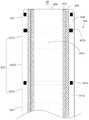
如图1所示,预塑型的输送鞘管包括单弯预塑型输送鞘管10。具体地,单弯预塑型输送鞘管10包括近端段11、远端段13和塑弯段15,近端段11和远端段13在自然状态下均为直型管,近端段11位于单弯预塑型输送鞘管10的近端一侧,远端段13位于单弯预塑型输送鞘管10的远端一侧。塑弯段15在自然状态下为一段弯曲形态的管结构,其数量为一段,塑弯段15位于近端段11和远端段13之间,近端段11和远端段13通过塑弯段15相连。近端段11的延伸方向与远端段13的延伸方向呈45°夹角。As shown in FIG. 1 , the preshaped delivery sheath includes a single bend preshapeddelivery sheath 10 . Specifically, the single-curved pre-shapeddelivery sheath 10 includes aproximal section 11, adistal section 13, and aplastic bending section 15. Both theproximal section 11 and thedistal section 13 are straight tubes in a natural state, and theproximal section 11 is located on the proximal side of the single-curved pre-shapeddelivery sheath 10 , and thedistal section 13 is located on the distal side of the single-curved pre-shapeddelivery sheath 10 . Theplastic bending section 15 is a section of curved pipe structure in the natural state, and its number is one section. Theplastic bending section 15 is located between theproximal section 11 and thedistal section 13, and theproximal section 11 and thedistal section 13 pass through theplastic bending Segment 15 is connected. The extension direction of theproximal section 11 and the extension direction of thedistal section 13 form an included angle of 45°.

如图2所示,人体包括心脏21和下腔静脉31,心脏21包括右心房23、左心房25、房间隔27和左心耳29。右心房23与下腔静脉31相连通。房间隔27位于右心房23与左心房29之间,房间隔27将右心房23与左心房29隔开,房间隔27具有第一端部271和第二端部272,第一端部271靠近心尖,第二端部272与第一端部相对设置并远离心尖,房间隔具有由第二端部272向第一端部271延伸的延伸方向。左心耳29大致呈桶状结构,其具有开放端和封闭端,开放端为开口结构,该开放端可使得左心耳29与左心房25相连通,封闭端对左心耳29进行封闭,左心耳29的中心轴线291与下腔静脉的延伸方向所形成的锐角大致为45°。As shown in FIG. 2 , the human body includes aheart 21 and aninferior vena cava 31 , and theheart 21 includes aright atrium 23 , aleft atrium 25 , aninteratrial septum 27 and a leftatrial appendage 29 . Theright atrium 23 communicates with theinferior vena cava 31 . Theinteratrial septum 27 is located between theright atrium 23 and theleft atrium 29, theatrial septum 27 separates theright atrium 23 from theleft atrium 29, theinteratrial septum 27 has afirst end 271 and asecond end 272, thefirst end 271 is close to The apex of the heart, thesecond end portion 272 is opposite to the first end portion and away from the apex of the heart, and the atrial septum has an extension direction extending from thesecond end portion 272 to thefirst end portion 271 . The leftatrial appendage 29 is roughly barrel-shaped, and has an open end and a closed end. The open end is an open structure. The open end allows the leftatrial appendage 29 to communicate with theleft atrium 25. The closed end closes the leftatrial appendage 29, and the leftatrial appendage 29 The acute angle formed by thecentral axis 291 and the extending direction of the inferior vena cava is approximately 45°.

单弯预塑型输送鞘管10在使用时,一般是经下腔静脉31进入右心房23,再对房间隔27进行穿刺使得单弯预塑型输送鞘管10的远端段13进入左心房25内,并且近端段11保持在下腔静脉31内。保持在下腔静脉31内的近端段11可视为与下腔静脉31同轴。由于左心耳29的中心轴线291与下腔静脉31的延伸方向形成的锐角大致为45°,也就相当于左心耳29的中心轴线291与近端段11形成的锐角为45°。在房间隔27的穿刺点选择正确的情况下,房间隔27不会改变近端段11与远端段13之间的夹角,也就是说,近端段11与穿刺后的远端段13的夹角为45°,相当于下腔静脉31的延伸方向与穿刺后的远端段13形成的锐角为45°。因此,单弯预塑型鞘管10的远端段13可伸入左心耳29内,且远端段13与左心耳29的中心轴线291重合。When in use, the single-curved pre-shapeddelivery sheath 10 generally enters theright atrium 23 through theinferior vena cava 31, and then punctures theinteratrial septum 27 so that thedistal section 13 of the single-curved pre-shapeddelivery sheath 10 enters theleft atrium 25, and theproximal segment 11 remains in theinferior vena cava 31. Theproximal segment 11 held within theinferior vena cava 31 can be considered coaxial with theinferior vena cava 31 . Since the acute angle formed by thecentral axis 291 of the leftatrial appendage 29 and the extending direction of theinferior vena cava 31 is approximately 45°, it is equivalent to that the acute angle formed by thecentral axis 291 of the leftatrial appendage 29 and theproximal segment 11 is 45°. When the puncture point of theinteratrial septum 27 is selected correctly, theinteratrial septum 27 will not change the angle between theproximal segment 11 and thedistal segment 13, that is, theproximal segment 11 and the punctureddistal segment 13 The included angle is 45°, which is equivalent to that the acute angle formed by the extension direction of theinferior vena cava 31 and the punctureddistal end section 13 is 45°. Therefore, thedistal section 13 of the single-curvedpreshaped sheath 10 can extend into the leftatrial appendage 29 , and thedistal section 13 coincides with thecentral axis 291 of the leftatrial appendage 29 .

但是在实际操作中,实际的穿刺点与理想的穿刺点经常会出现偏差,并且有部分患者的左心耳29的中心轴线291与下腔静脉31的延伸方向的夹角小于45°,相当于左心耳29以封闭端为轴,左心耳29的开口向房间隔29的第一端部271一侧偏转一定角度。在对房间隔29进行穿刺时,当房间隔穿刺的位置不合适的时候,例如实际穿刺点相较于理想穿刺点偏高,即在房间隔29的长度方向,实际的穿刺点朝远离心尖的方向偏离理想的穿刺点,单弯预塑型输送鞘管10的远端段13可能在左心耳29的开口处与左心耳29的侧壁相抵,造成单弯预塑型输送鞘管10的远端段13无法伸入左心耳内,并且单弯预塑型输送鞘管10的远端段13无法与左心耳29的中心轴线291同轴。在此情况下,输送或者释放左心耳封堵器,左心耳封堵器的固定盘难以固定于左心耳29的内壁,左心耳封堵器易脱落造成器械栓塞。However, in actual operation, the actual puncture point often deviates from the ideal puncture point, and in some patients, the angle between thecentral axis 291 of the leftatrial appendage 29 and the extension direction of theinferior vena cava 31 is less than 45°, which is equivalent to the left Theatrial appendage 29 takes the closed end as the axis, and the opening of the leftatrial appendage 29 deflects to the side of thefirst end 271 of theinteratrial septum 29 at a certain angle. When puncturing theinteratrial septum 29, when the position of the interatrial septum puncture is inappropriate, for example, the actual puncture point is higher than the ideal puncture point, that is, in the length direction of theinteratrial septum 29, the actual puncture point faces away from the apex. If the direction deviates from the ideal puncture point, thedistal section 13 of the single-curved pre-shapeddelivery sheath 10 may abut against the side wall of the leftatrial appendage 29 at the opening of the leftatrial appendage 29, resulting in the far-end section 13 of the single-curved pre-shapeddelivery sheath 10. Theend section 13 cannot extend into the left atrial appendage, and thedistal end section 13 of the single-curvedpreshaped delivery sheath 10 cannot be coaxial with thecentral axis 291 of the leftatrial appendage 29 . In this case, when the left atrial appendage occluder is delivered or released, the fixed plate of the left atrial appendage occluder is difficult to be fixed on the inner wall of the leftatrial appendage 29, and the left atrial appendage occluder is easy to fall off, resulting in device embolism.

在手术过程中,操作者可能会通过移动或者转动单弯预塑型输送鞘管10的近端以改变远端段13的位置,但是由于穿刺点偏高,不论如何移动或推拉,也无法使得远端段13与左心耳29的中心轴线29同轴。During the operation, the operator may change the position of thedistal section 13 by moving or rotating the proximal end of the single-curved pre-shapeddelivery sheath 10, but because the puncture point is too high, no matter how much it moves or pushes or pulls, it cannot make it Thedistal segment 13 is coaxial with thecentral axis 29 of the leftatrial appendage 29 .

发明内容Contents of the invention

基于此,有必要提供一种输送鞘管,以解决现有技术中输送鞘管无法与左心耳同轴的问题。Based on this, it is necessary to provide a delivery sheath to solve the problem in the prior art that the delivery sheath cannot be coaxial with the left atrial appendage.

一种输送鞘管,包括管体部分,管体部分包括外层管和牵引结构,外层管包括连接管、管身及远端管,管身位于连接管与远端管之间,管身包括第一柔性管、间隔管以及第二柔性管,间隔管设于第一柔性管的远端与第二柔性管的近端之间,连接管的硬度大于第一、第二柔性管的硬度,间隔管的硬度大于第一、第二柔性管的硬度,牵引结构包括第一牵引丝和第二牵引丝,第一牵引丝与第一柔性管相连,第二牵引丝与第二柔性管相连,第一牵引丝和第二牵引丝均在外层管内延伸,且第一牵引丝的自由端和第二牵引丝的自由端均延伸出连接管的近端,第一牵引丝相对管身可滑动,并能够带动第一柔性管在第一平面内产生弯曲,第二牵引丝相对管身可滑动,能够带动第二柔性管在第二平面内产生弯曲,第一平面与第二平面相交、平行或共面。A delivery sheath, including a tube body part, the tube body part includes an outer tube and a traction structure, the outer tube includes a connecting tube, a tube body and a distal tube, the tube body is located between the connecting tube and the distal tube, and the tube body It includes a first flexible tube, a spacer tube and a second flexible tube, the spacer tube is arranged between the distal end of the first flexible tube and the proximal end of the second flexible tube, and the hardness of the connecting tube is greater than that of the first and second flexible tubes , the hardness of the spacer tube is greater than the hardness of the first and second flexible tubes, the traction structure includes a first traction wire and a second traction wire, the first traction wire is connected with the first flexible pipe, and the second traction wire is connected with the second flexible pipe , the first pulling wire and the second pulling wire both extend in the outer tube, and the free ends of the first pulling wire and the free end of the second pulling wire both extend out of the proximal end of the connecting tube, and the first pulling wire is slidable relative to the tube body , and can drive the first flexible tube to bend in the first plane, the second drawing wire can slide relative to the tube body, and can drive the second flexible tube to bend in the second plane, the first plane intersects and is parallel to the second plane or coplanar.

在其中一个实施例中,第一柔性管的硬度大于或等于第二柔性管的硬度。In one embodiment, the stiffness of the first flexible tube is greater than or equal to the stiffness of the second flexible tube.

在其中一个实施例中,管身还包括过渡管,In one of the embodiments, the pipe body also includes a transition pipe,

过渡管设于间隔管与第一柔性管之间,过渡管的硬度小于间隔管的硬度,过渡管的硬度大于第一柔性管的硬度,或,过渡管设于间隔管与第二柔性管之间,过渡管的硬度小于间隔管的硬度,过渡管的硬度大于第二柔性管的硬度,或,过渡管设于连接管与第一柔性管之间,过渡管的硬度小于连接管的硬度,过渡管的硬度大于第一柔性管的硬度,或,过渡管设于远端管与第二柔性管之间,过渡管的硬度小于远端管的硬度,过渡管的硬度大于第二柔性管的硬度。The transition tube is arranged between the spacer tube and the first flexible tube, the hardness of the transition tube is smaller than the hardness of the spacer tube, the hardness of the transition tube is greater than the hardness of the first flexible tube, or the transition tube is set between the spacer tube and the second flexible tube Between, the hardness of the transition pipe is less than the hardness of the interval pipe, the hardness of the transition pipe is greater than the hardness of the second flexible pipe, or, the transition pipe is arranged between the connecting pipe and the first flexible pipe, and the hardness of the transition pipe is less than the hardness of the connecting pipe, The hardness of the transition tube is greater than that of the first flexible tube, or the transition tube is arranged between the distal tube and the second flexible tube, the hardness of the transition tube is less than that of the distal tube, and the hardness of the transition tube is greater than that of the second flexible tube hardness.

在其中一个实施例中,第一平面与第二平面相互垂直。In one embodiment, the first plane and the second plane are perpendicular to each other.

在其中一个实施例中,牵引结构还包括固定于管身中的第一固定结构和/或第二固定结构,第一固定结构设于第一柔性管的远端,第二固定结构设于第二柔性管的远端,第一固定结构和/或第二固定结构的侧壁开设有第一连接孔、第二连接孔及第三连接孔,沿第一固定结构和/或第二固定结构的圆周方向,第二连接孔位于第一连接孔和第三连接孔之间,第一连接孔、第二连接孔和第三连接孔的孔心的连线可形成三角形;三角形中在第二连接孔的孔心所形成的内角为钝角,第一牵引丝依次穿过第一固定结构的第一连接孔、第二连接孔、第三连接孔以与第一固定结构相连,和/或,第二牵引丝依次穿过第二固定结构的第一连接孔、第二连接孔、第三连接孔以与第二固定结构相连。In one of the embodiments, the traction structure further includes a first fixing structure and/or a second fixing structure fixed in the tube body, the first fixing structure is arranged at the distal end of the first flexible tube, and the second fixing structure is arranged at the first flexible tube. At the far end of the two flexible tubes, the side walls of the first fixing structure and/or the second fixing structure are provided with a first connecting hole, a second connecting hole and a third connecting hole, along the first fixing structure and/or the second fixing structure In the circumferential direction, the second connection hole is located between the first connection hole and the third connection hole, and the connecting line of the center of the first connection hole, the second connection hole and the third connection hole can form a triangle; The inner angle formed by the center of the connecting hole is an obtuse angle, and the first drawing wire passes through the first connecting hole, the second connecting hole, and the third connecting hole of the first fixing structure in order to be connected with the first fixing structure, and/or, The second pulling wire passes through the first connection hole, the second connection hole and the third connection hole of the second fixing structure in order to be connected with the second fixing structure.

在其中一个实施例中,管身还包括设于管身中的至少一个支撑件,当支撑件的数量为一个时,支撑件设于第一柔性管或第二柔性管所在的区间段内,当支撑件的数量为多个时,第一柔性管和第二柔性管所在的区间段内均设有支撑件。In one of the embodiments, the pipe body further includes at least one support member arranged in the pipe body. When the number of the support member is one, the support member is arranged in the section where the first flexible pipe or the second flexible pipe is located, When there are multiple support members, support members are provided in the section where the first flexible pipe and the second flexible pipe are located.

在其中一个实施例中,支撑件包括沿螺旋线延伸的延伸体,沿平行于支撑件的中心轴线方向切割支撑件的一侧壁后,再沿支撑件的径向展开切割后的支撑件,延伸体与支撑件的中心轴线形成的夹角E的范围为60°至90°。In one of the embodiments, the support member includes an extension body extending along a helix, and after cutting a side wall of the support member along a direction parallel to the central axis of the support member, the cut support member is expanded along the radial direction of the support member, The angle E formed by the extension body and the central axis of the support member ranges from 60° to 90°.

在其中一个实施例中,第一柔性管在自然状态下为弯曲形态,第一柔性管近端端部的延伸方向与第一柔性管远端端部的延伸方向形成夹角B,夹角B的范围为45°至90°。In one of the embodiments, the first flexible tube is in a curved shape in a natural state, and the extension direction of the proximal end of the first flexible tube forms an included angle B with the extension direction of the distal end of the first flexible tube, and the included angle B The range is 45° to 90°.

在其中一个实施例中,间隔管在其自然状态下为直线形态或弯曲形态,当间隔管在其自然状态下弯曲形态时,间隔管在第二平面内呈弯曲形态,间隔管的弯曲方向与第二柔性管的弯曲方向相反,当间隔管在其自然状态下为直线形态时,间隔管在第二平面内呈直线形态。In one of the embodiments, the spacer tube is straight or curved in its natural state, and when the spacer tube is curved in its natural state, the spacer tube is curved in the second plane, and the bending direction of the spacer tube is the same as The bending direction of the second flexible tube is opposite, and when the spacing tube is straight in its natural state, the spacing tube is straight in the second plane.

在其中一个实施例中还提供一种医疗器械,医疗器械包括上述的输送鞘管。In one embodiment, there is also provided a medical device, which includes the above delivery sheath.

上述输送鞘管使用时,输送鞘管由下腔静脉进入右心房,然后再对房间隔进行穿刺,在穿刺后输送鞘管的远端管和管身的一部分进入左心房,然后通过第一牵引丝对第一柔性管的远端施加牵引力,第一柔性管在第一平面内弯曲变形并带动远端管运动,然后通过第二牵引丝对第二柔性管的远端施加牵引力,第二柔性管在第二平面内弯曲变形并带动远端管运动,由于第一平面和第二平面相交,因此通过第一牵引丝和第二牵引丝可在两个维度上调整远端管的位置,使得远端管与左心耳实现同轴,连接管的硬度大于第一柔性管和第二柔性管的硬度,可为输送鞘管提供足够轴向支撑力,使得在手术过程中,第一柔性管和第二柔性管在稳定的结构上进行调弯,进而使得第一柔性管和第二柔性管的调弯可控以及弯曲形态可预测,进而使得输送管鞘管能够快速完成与左心耳的同轴的操作,间隔管的硬度大于第一柔性管和第二柔性管的硬度,可以避免对第二柔性管调弯时的支点移动至第一柔性管上,进而达到避免第二柔性管调弯时影响第一柔性管的形态的效果,使得输送管鞘管能够快速完成与左心耳的同轴的操作。When the above-mentioned delivery sheath is used, the delivery sheath enters the right atrium from the inferior vena cava, and then punctures the interatrial septum. The wire applies traction to the distal end of the first flexible tube, the first flexible tube bends and deforms in the first plane and drives the distal tube to move, and then applies traction to the distal end of the second flexible tube through the second traction wire, and the second flexible tube The tube bends and deforms in the second plane and drives the distal tube to move. Since the first plane and the second plane intersect, the position of the distal tube can be adjusted in two dimensions through the first and second pulling wires, so that The distal tube is coaxial with the left atrial appendage, and the hardness of the connecting tube is greater than that of the first flexible tube and the second flexible tube, which can provide sufficient axial support for the delivery sheath, so that during the operation, the first flexible tube and the second flexible tube can provide sufficient axial support. The second flexible tube is bent on a stable structure, so that the bending of the first flexible tube and the second flexible tube can be controlled and the bending shape can be predicted, so that the delivery tube sheath can be quickly completed coaxial with the left atrial appendage operation, the hardness of the spacer tube is greater than the hardness of the first flexible tube and the second flexible tube, which can prevent the fulcrum from moving to the first flexible tube when the second flexible tube is bent, thereby avoiding the bending of the second flexible tube The effect of affecting the shape of the first flexible tube enables the coaxial operation of the delivery tube sheath and the left atrial appendage to be completed quickly.

附图说明Description of drawings

图1为现有技术中单弯预塑型鞘管的结构示意图。Fig. 1 is a schematic structural view of a single-curved pre-shaped sheath in the prior art.

图2为现有技术中单弯预塑型鞘管使用时的一状态图。Fig. 2 is a state diagram of the single-curved pre-shaped sheath in use in the prior art.

图3为一实施例的输送鞘管的剖视结构示意图。Fig. 3 is a schematic cross-sectional structure diagram of a delivery sheath according to an embodiment.

图4为一实施例的输送鞘管的局部剖视图。4 is a partial cross-sectional view of a delivery sheath of an embodiment.

图5为一实施例的输送鞘管的局部剖视图。5 is a partial cross-sectional view of a delivery sheath of an embodiment.

图6为一实施例的第一固定结构的立体图。Fig. 6 is a perspective view of a first fixing structure of an embodiment.

图7为一实施例的第一牵引丝与第一固定结构配合的结构示意图。Fig. 7 is a structural schematic diagram of the cooperation between the first pulling wire and the first fixing structure according to an embodiment.

图8为一实施例的连接管的结构示意图。Fig. 8 is a schematic structural diagram of a connecting pipe according to an embodiment.

图9为一实施例的输送鞘管使用时的状态图。Fig. 9 is a state diagram of the delivery sheath in use according to an embodiment.

图10为图9中的A-A的剖视图。Fig. 10 is a sectional view of A-A in Fig. 9 .

图11为一实施例的输送鞘管的结构示意图。Fig. 11 is a schematic structural view of a delivery sheath according to an embodiment.

图12为一实施例的输送鞘管的结构示意图。Fig. 12 is a schematic structural view of a delivery sheath according to an embodiment.

图13为一实施例的输送鞘管的剖视结构示意图。Fig. 13 is a schematic cross-sectional structure diagram of a delivery sheath according to an embodiment.

图14为一实施例的输送鞘管的剖视结构示意图。Fig. 14 is a schematic cross-sectional structure diagram of a delivery sheath according to an embodiment.

图15为一实施例的支撑件的结构示意图。Fig. 15 is a schematic structural diagram of a support member according to an embodiment.

图16为一实施例的支撑件的结构示意图。Fig. 16 is a schematic structural diagram of a support member according to an embodiment.

图17为一实施例的支撑件的结构示意图。Fig. 17 is a schematic structural diagram of a support member according to an embodiment.

图18为一实施例的支撑件的结构示意图。Fig. 18 is a schematic structural diagram of a support member according to an embodiment.

图19为一实施例的支撑件的结构示意图。Fig. 19 is a schematic structural diagram of a support member according to an embodiment.

具体实施方式detailed description

为使本发明的上述目的、特征和优点能够更加明显易懂,下面结合附图对本发明的具体实施方式做详细的说明。在下面的描述中阐述了很多具体细节以便于充分理解本发明。但是本发明能够以很多不同于在此描述的其它方式来实施,本领域技术人员可以在不违背本发明内涵的情况下做类似改进,因此本发明不受下面公开的具体实施的限制。In order to make the above objects, features and advantages of the present invention more comprehensible, specific implementations of the present invention will be described in detail below in conjunction with the accompanying drawings. In the following description, numerous specific details are set forth in order to provide a thorough understanding of the present invention. However, the present invention can be implemented in many other ways different from those described here, and those skilled in the art can make similar improvements without departing from the connotation of the present invention, so the present invention is not limited by the specific implementations disclosed below.

需要说明的是,当元件被称为“固定于”或“设置于”另一个元件,它可以直接在另一个元件上或者也可以存在居中的元件。当一个元件被认为是“连接”另一个元件,它可以是直接连接到另一个元件或者可能同时存在居中元件。本文所使用的术语“垂直的”、“水平的”、“左”、“右”以及类似的表述只是为了说明的目的,并不表示是唯一的实施方式。It should be noted that when an element is referred to as being “fixed on” or “disposed on” another element, it may be directly on the other element or there may be an intervening element. When an element is referred to as being "connected to" another element, it can be directly connected to the other element or intervening elements may also be present. The terms "vertical," "horizontal," "left," "right," and similar expressions are used herein for purposes of illustration only and are not intended to represent the only embodiments.

除非另有定义,本文所使用的所有的技术和科学术语与属于本发明的技术领域的技术人员通常理解的含义相同。本文中在本发明的说明书中所使用的术语只是为了描述具体的实施方式的目的,不是旨在于限制本发明。本文所使用的术语“及/或”包括一个或多个相关的所列项目的任意的和所有的组合。Unless otherwise defined, all technical and scientific terms used herein have the same meaning as commonly understood by one of ordinary skill in the technical field of the invention. The terminology used herein in the description of the present invention is only for the purpose of describing specific embodiments, and is not intended to limit the present invention. As used herein, the term "and/or" includes any and all combinations of one or more of the associated listed items.

为了更加清楚地描述本申请的结构,采用“远端”、“近端”作为方位词,其中“远端”表示手术过程中远离操作者的一端,“近端”表示手术过程中靠近操作者的一端。In order to describe the structure of this application more clearly, "distal end" and "proximal end" are used as orientation words, wherein "distal end" means the end far away from the operator during the operation, and "near end" means the end close to the operator during the operation one end.

第一实施例first embodiment

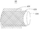
请参阅图3,本实施例提供的输送鞘管60为可调弯的鞘管,输送鞘管60包括管体部分600,管体部分600在自然状态下呈直线形态。Please refer to FIG. 3 , thedelivery sheath 60 provided in this embodiment is an adjustable and bendable sheath, and thedelivery sheath 60 includes atube body portion 600 , which is straight in a natural state.

管体部分600包括由内至外层叠的内层管610、中间层620、外层管630和牵引结构640。Thetube body part 600 includes aninner layer tube 610 , amiddle layer 620 , anouter layer tube 630 and atraction structure 640 stacked from inside to outside.

内层管610由高分子材料制成,具有高润滑性、低摩擦性,其内表面光滑,可保证植入器械(例如左心耳封堵器,图未示)顺畅地从内表面通过,其材料可以为PTFE(聚四氟乙烯)等高分子材料。Theinner tube 610 is made of polymer material, has high lubricity and low friction, and its inner surface is smooth, which can ensure that implanted instruments (such as left atrial appendage occluder, not shown) pass through the inner surface smoothly. The material can be polymer materials such as PTFE (polytetrafluoroethylene).

中间层620为金属层,贴设于内层管610的外表面上。请参阅图4,中间层620可以是由金属丝编织的编织管。请参阅图5,中间层620也可以是金属弹簧管。编织管是由编织机利用金属丝编织而成。金属弹簧管是由绕制弹簧的弹簧机绕制而成。Themiddle layer 620 is a metal layer, which is pasted on the outer surface of theinner tube 610 . Referring to FIG. 4 , themiddle layer 620 may be a braided tube braided by metal wires. Referring to FIG. 5 , themiddle layer 620 can also be a metal spring tube. The braided tube is braided by a braiding machine using metal wire. Metal spring tubes are wound by a spring machine that winds springs.

外层管630由硬度不同(或者说是弹性不同)的高分子材料制成,其材料可以为Pebax(尼龙弹性体)等高分子材料。Theouter tube 630 is made of polymer materials with different hardness (or different elasticity), such as Pebax (nylon elastomer) and other polymer materials.

在制作输送鞘管60的过程中,将中间层620束紧并贴设于内层管610的外表面上,然后套上外层管630,再进行热熔成型,热熔后的内层管610的外表面与外层管630的内表面相接合,进而使得内层管610、中间层620和外层管630形成一体的结构。In the process of making thedelivery sheath tube 60, themiddle layer 620 is tightened and attached to the outer surface of theinner layer tube 610, and then theouter layer tube 630 is put on, and then thermally melted, and the inner layer tube after thermal melting The outer surface of theouter tube 610 is joined with the inner surface of theouter tube 630 , so that theinner tube 610 , themiddle layer 620 and theouter tube 630 form an integrated structure.

请再次参阅图3,外层管630包括连接管631、管身632及远端管633。连接管631位于管身632的近端,远端管633位于管身632的远端,管身632位于连接管631与远端管633之间,管身632的一端与连接管631相连,管身632的另一端与远端管633相连。Please refer to FIG. 3 again, theouter tube 630 includes a connectingtube 631 , atube body 632 and adistal tube 633 . The connectingpipe 631 is located at the proximal end of thepipe body 632, thedistal pipe 633 is located at the far end of thepipe body 632, thepipe body 632 is located between the connectingpipe 631 and thedistal pipe 633, one end of thepipe body 632 is connected with the connectingpipe 631, and thepipe body 632 is connected to the connectingpipe 631. The other end of thebody 632 is connected with thedistal tube 633 .

管身632包括第一柔性管6321、间隔管6322以及第二柔性管6323。第一柔性管6321的近端与连接管631相连。间隔管6322在其自然状态下为直形管,间隔管6322设于第一柔性管6321的远端与第二柔性管6323的近端之间。第二柔性管6323的远端与远端管633的近端相连,第一柔性管6321和第二柔性管6323为可调弯的管状结构,即第一柔性管6321和第二柔性管6323受牵引力作用可发生弯曲变形,连接管631的硬度大于第一柔性管6321和第二柔性管6323的硬度,间隔管6322的硬度大于第一柔性管6321和第二柔性管6323的硬度,远端管633的硬度大于第一柔性管6321和第二柔性管6323的硬度,第一柔性管6321和第二柔性管6323受牵引力作用弯曲变形时,连接管631、间隔管6322和远端管633均不发生弯曲变形。Thetube body 632 includes a firstflexible tube 6321 , aninterval tube 6322 and a secondflexible tube 6323 . The proximal end of the firstflexible tube 6321 is connected with the connectingtube 631 . Thespacer tube 6322 is a straight tube in its natural state, and thespacer tube 6322 is arranged between the distal end of the firstflexible tube 6321 and the proximal end of the secondflexible tube 6323 . The distal end of the secondflexible tube 6323 is connected to the proximal end of thedistal tube 633, and the firstflexible tube 6321 and the secondflexible tube 6323 are adjustable bendable tubular structures, that is, the firstflexible tube 6321 and the secondflexible tube 6323 are Bending deformation can occur under the action of traction, the hardness of the connectingtube 631 is greater than the hardness of the firstflexible tube 6321 and the secondflexible tube 6323, the hardness of thespacer tube 6322 is greater than the hardness of the firstflexible tube 6321 and the secondflexible tube 6323, the distal tube The hardness of 633 is greater than that of the firstflexible tube 6321 and the secondflexible tube 6323. When the firstflexible tube 6321 and the secondflexible tube 6323 are bent and deformed by the traction force, the connectingtube 631, thespacer tube 6322 and thedistal tube 633 are not Bending deformation occurs.

牵引结构640包括第一牵引丝641a、第二牵引丝642a、第一固定结构和641b第二固定结构642b。The pullingstructure 640 includes a first pullingwire 641a, a second pullingwire 642a, a first fixing structure and 641b asecond fixing structure 642b.

第一牵引丝641a与第一柔性管6321的远端相连,第二牵引丝642a与第二柔性管6323的远端相连,第一牵引丝641a和第二牵引丝642a均在外层管630内直线延伸,且第一牵引丝641a的自由端和第二牵引丝642a的自由端均延伸出连接管631的近端。第一牵引丝641a相对管身632可滑动,并能够带动第一柔性管6321在第一平面P(在图10中示出)内向受力一侧产生弯曲。第二牵引丝642a相对管身632可滑动,能够带动第二柔性管6323在第二平面Q(在图10中示出)内向受力一侧产生弯曲。第一平面P与第二平面Q相交。The first pullingwire 641a is connected to the distal end of the firstflexible tube 6321, the second pullingwire 642a is connected to the distal end of the secondflexible tube 6323, and both the first pullingwire 641a and the second pullingwire 642a are straight in theouter tube 630 The free end of the first pullingwire 641a and the free end of the second pullingwire 642a both extend out of the proximal end of the connectingtube 631 . The first pullingwire 641a is slidable relative to thetube body 632, and can drive the firstflexible tube 6321 to bend toward the force receiving side in the first plane P (shown in FIG. 10 ). The second pullingwire 642a is slidable relative to thetube body 632, and can drive the secondflexible tube 6323 to bend toward the force-bearing side in the second plane Q (shown in FIG. 10 ). The first plane P intersects the second plane Q.

第一固定结构641b和第二固定结构642b均固定于管身632中,第一固定结构641b和第二固定结构642b均为环状体。具体地,第一固定结构641b设于第一柔性管6321的远端,第一固定结构641b的远端与第一柔性管6321的远端平齐,且第一固定结构641b嵌入第一柔性管6321中。第二固定结构642b设于第二柔性管6323的远端,第二固定结构642b的远端与第二柔性管6323的远端平齐,且第二固定结构642b嵌入第二柔性管6323中。Both thefirst fixing structure 641b and thesecond fixing structure 642b are fixed in thetube body 632, and both thefirst fixing structure 641b and thesecond fixing structure 642b are annular bodies. Specifically, thefirst fixing structure 641b is arranged at the distal end of the firstflexible tube 6321, the distal end of thefirst fixing structure 641b is flush with the distal end of the firstflexible tube 6321, and thefirst fixing structure 641b is embedded in the firstflexible tube 6321 in. Thesecond fixing structure 642b is disposed on the distal end of the secondflexible tube 6323 , the distal end of thesecond fixing structure 642b is flush with the distal end of the secondflexible tube 6323 , and thesecond fixing structure 642b is embedded in the secondflexible tube 6323 .

第一固定结构641b和第二固定结构642b的侧壁开设三个连接孔。由于第一固定结构641b和第二固定结构642b上的连接孔的分布相同,在此仅以第一固定结构641b上的连接孔进行说明,请参阅图6,第一固定结构641b的侧壁开设有第一连接孔6411a、第二连接孔6411b和第三连接孔6411c。沿第一固定结构641b的圆周方向,第二连接孔6411b位于第一连接孔6411a与第三连接孔6411c之间,第一连接孔6411a、第二连接孔6411b和第三连接孔6411c的孔心的连线可形成一个三角形6412。三角形6412在第二连接孔6411b的孔心所形成的内角A为钝角。第一牵引丝641a依次穿过第一连接孔6411a、第二连接孔6411b和第三连接孔6411c以与第一固定结构641b相连。第二牵引丝642a依次穿过第二固定结构642b的三个连接孔6411以与第二固定结构642b相连。The side walls of thefirst fixing structure 641b and thesecond fixing structure 642b define three connection holes. Since the distribution of the connecting holes on thefirst fixing structure 641b and thesecond fixing structure 642b are the same, only the connecting holes on thefirst fixing structure 641b will be described here. Please refer to FIG. 6, the side wall of thefirst fixing structure 641b has There are afirst connection hole 6411a, asecond connection hole 6411b, and athird connection hole 6411c. Along the circumferential direction of thefirst fixing structure 641b, the second connectinghole 6411b is located between the first connectinghole 6411a and the third connectinghole 6411c, and the centers of the first connectinghole 6411a, the second connectinghole 6411b and the third connectinghole 6411c The connecting lines of can form atriangle 6412. The interior angle A formed by thetriangle 6412 at the center of the second connectinghole 6411b is an obtuse angle. The first pullingwire 641a passes through the first connectinghole 6411a, the second connectinghole 6411b and the third connectinghole 6411c in order to be connected with thefirst fixing structure 641b. The second pullingwire 642a sequentially passes through the threeconnection holes 6411 of thesecond fixing structure 642b to be connected with thesecond fixing structure 642b.

请参阅图7,第一连接孔6411a和第三连接孔6411c的孔心位于第一固定结构641b的同一圆周线上,第一牵引丝641a依次穿过第一连接孔6411a、第二连接孔6411b和第三连接孔6411c以与第一固定结构641b相连,使得第一牵引丝641a在第一固定结构641b的第一连接孔6411a、第二连接孔6411b和第三连接孔6411c三处形成的夹角均为钝角,进而可以避免第一牵引丝641a在使用过程中出现应力集中,提高使用寿命。Please refer to Fig. 7, the centers of the first connectinghole 6411a and the third connectinghole 6411c are located on the same circumferential line of thefirst fixing structure 641b, and the first pullingwire 641a passes through the first connectinghole 6411a and the second connectinghole 6411b in sequence and the third connectinghole 6411c to be connected with thefirst fixing structure 641b, so that the first pullingwire 641a forms clips at three places of the first connectinghole 6411a, the second connectinghole 6411b and the third connectinghole 6411c of thefirst fixing structure 641b The angles are all obtuse, thereby avoiding stress concentration of the first pullingwire 641a during use and improving the service life.

可以理解地,第二固定结构642b的结构与第一固定结构641b的结构相同,第二牵引丝642a与第二固定结构642b之间的连接方式与第一牵引丝641a与第一固定结构641b的连接方式相同,也可以避免第二牵引丝642a在使用过程中出现应力集中。It can be understood that the structure of thesecond fixing structure 642b is the same as that of thefirst fixing structure 641b, and the connection mode between thesecond drawing wire 642a and thesecond fixing structure 642b is the same as that of thefirst drawing wire 641a and thefirst fixing structure 641b. The same connection method can also avoid stress concentration of the second pullingwire 642a during use.

在其他实施例中,牵引结构640只包括上述的第一固定结构641b以及与之相连的第一牵引丝641a,或者,牵引结构640只包括上述的第二固定结构642b以及与之相连的第二牵引丝642a。In other embodiments, the pullingstructure 640 only includes the above-mentioned first fixingstructure 641b and the first pullingwire 641a connected thereto, or, the pullingstructure 640 only includes the above-mentionedsecond fixing structure 642b and the second connectingwire 641b connected thereto. Pullwire 642a.

第一柔性管6321的硬度范围为10D至40D,可以保证第一柔性管6321在第一平面P内可调弯。第二柔性管6323的硬度范围为10D至40D,可以保证第二柔性管6323在第二平面Q内可调弯。The hardness range of the firstflexible tube 6321 is 10D to 40D, which can ensure that the firstflexible tube 6321 can be adjusted to bend in the first plane P. The hardness of the secondflexible tube 6323 ranges from 10D to 40D, which can ensure that the secondflexible tube 6323 can be adjusted to bend in the second plane Q.

连接管631的硬度范围为55D至72D,即连接管631的硬度大于第一柔性管6321和第二柔性管6323的硬度,如此,在输送鞘管60满足适应血管形态的要求下,连接管631为输送鞘管60提供足够轴向支撑力,使得在手术过程中,第一柔性管6321和第二柔性管6323在稳定的结构上进行调弯,使得第一柔性管6321和第二柔性管6323的调弯可控以及弯曲可预测,使得输送管鞘管60能够快速完成与左心耳的同轴的操作。间隔管6322的硬度范围为55D至72D,即间隔管6322的硬度大于第一柔性管6321和第二柔性管6323的硬度,可以避免第二柔性管6323调弯时的支点移动至第一柔性管6321上,进而达到避免第二柔性管6323调弯时影响第一柔性管6321的形态的效果,使得输送管鞘管60能够快速完成与左心耳的同轴的操作。远端管633的硬度范围为55D至72D,可以保证远端管633的轴向强度,使远端管633在释放或回收植入器械时,始终保持直线形态,保证植入器械能够顺畅的释放和回收。优选地,连接管631、间隔管6322和远端管633硬度相同,硬度均为72D,可以在输送鞘管60满足适应血管形态的要求下,提供足够的轴向支撑力。The hardness of the connectingtube 631 ranges from 55D to 72D, that is, the hardness of the connectingtube 631 is greater than the hardness of the firstflexible tube 6321 and the secondflexible tube 6323. In this way, when thedelivery sheath 60 meets the requirements of adapting to the shape of the blood vessel, the connectingtube 631 Provide sufficient axial support for thedelivery sheath 60, so that during the operation, the firstflexible tube 6321 and the secondflexible tube 6323 are bent on a stable structure, so that the firstflexible tube 6321 and the secondflexible tube 6323 The controllable and predictable bending adjustment of thedelivery tube sheath 60 can quickly complete the coaxial operation with the left atrial appendage. The hardness of thespacer tube 6322 ranges from 55D to 72D, that is, the hardness of thespacer tube 6322 is greater than the hardness of the firstflexible tube 6321 and the secondflexible tube 6323, which can prevent the fulcrum of the secondflexible tube 6323 from moving to the first flexible tube when it is bent. 6321, so as to avoid the effect of affecting the shape of the firstflexible tube 6321 when the secondflexible tube 6323 is bent, so that thedelivery tube sheath 60 can quickly complete the coaxial operation with the left atrial appendage. The hardness range of thedistal tube 633 is 55D to 72D, which can ensure the axial strength of thedistal tube 633, so that thedistal tube 633 always maintains a straight line when releasing or recovering the implanted device, ensuring the smooth release of the implanted device and recycling. Preferably, the connectingtube 631 , thespacer tube 6322 and thedistal tube 633 have the same hardness of 72D, which can provide sufficient axial support force when thedelivery sheath 60 meets the requirements of adapting to the shape of the blood vessel.

第一柔性管6321的硬度大于或等于第二柔性管6323的硬度,也可以避免第二柔性管6323在调弯时,影响第一柔性管6321的形态,进而可以避免由于第二柔性管6323对第一柔性管6321的形态影响所造成的远端管633无法与左心耳同轴。The hardness of the firstflexible tube 6321 is greater than or equal to the hardness of the secondflexible tube 6323, which can also prevent the secondflexible tube 6323 from affecting the shape of the firstflexible tube 6321 when it is bent, thereby avoiding the impact of the secondflexible tube 6323 on the The shape of the firstflexible tube 6321 causes thedistal tube 633 to be unable to be coaxial with the left atrial appendage.

第一牵引丝641a采用高强度材料,例如碳纤维丝或者镍钛丝。第一牵引丝641a均为多股丝,与单根丝相比,多股丝的疲劳应力更小,与第一固定结构641b连接时,不易发生疲劳应力集中断裂,即使第一牵引丝641a中的某根丝断裂,其他丝也可调节鞘管的角度。可以延长第一牵引丝641a的使用寿命,并且,当第一牵引丝641a的某根丝发生断裂,则会发出的异响声(例如“嘭”的声响),可以提醒操着者,第一牵引丝641a中的某根丝已损坏,应小心使用,尽快结束操作过程。Thefirst drawing wire 641a is made of high-strength material, such as carbon fiber wire or nickel-titanium wire. The first pullingwires 641a are all multi-strand wires. Compared with single wires, the fatigue stress of multi-strand wires is smaller. If one of the wires is broken, other wires can also adjust the angle of the sheath. The service life of thefirst drawing wire 641a can be extended, and when a certain wire of thefirst drawing wire 641a breaks, an abnormal sound (such as a "bang" sound) can be issued, which can remind the operator that the first One of the pullingwires 641a has been damaged, it should be used with care and the operation should be finished as soon as possible.

第二牵引丝642a的结构与第一牵引丝641a的结构和材料均相同,均为多股丝。The structure and material of thesecond drawing wire 642a are the same as that of thefirst drawing wire 641a, and both are multi-strand wires.

请参图8,连接管631包括近端部分6311和远端部分6312,远端部分6312与管身632的第一柔性管6321相连。输送鞘管60在近端部分6311的长度区间内具有第一壁厚,输送鞘管60在远端部分6312的长度区间内具有第二壁厚,第一壁厚大于第二壁厚。进而增强输送鞘管60在近端部分6311的长度区间内的强度,在对输送鞘管60调弯时,可避免牵引结构640带动输送鞘管60的近端部分6311的长度区间内的管体发生弯曲变形(即可避免近端部分6311的长度区间内对应的输送鞘管60发生“驼背”变形)。进而可避免输送鞘管60“驼背”所导致压迫血管和内脏器官。Referring to FIG. 8 , the connectingtube 631 includes aproximal portion 6311 and adistal portion 6312 , and thedistal portion 6312 is connected to the firstflexible tube 6321 of thetube body 632 . Thedelivery sheath 60 has a first wall thickness over the length of theproximal portion 6311, and thedelivery sheath 60 has a second wall thickness over the length of thedistal portion 6312, the first wall thickness being greater than the second wall thickness. Further, the strength of thedelivery sheath 60 in the length interval of theproximal portion 6311 is enhanced, and when thedelivery sheath 60 is bent, thetraction structure 640 can be prevented from driving the tube body in the length interval of theproximal portion 6311 of thedelivery sheath 60. Bending deformation occurs (that is, the correspondingdelivery sheath 60 within the length interval of theproximal portion 6311 is prevented from being “hunchbacked” deformed). Furthermore, it is possible to avoid compression of blood vessels and internal organs caused by the "hunchback" of thedelivery sheath 60 .

具体地,输送鞘管60在其外层管630之外设有一层硬度高的高分子材料,该硬度较高的高分子材料的硬度范围为63D至72D,该硬度较高的高分子材料设于近端部分6311对应的长度区间内,可增强输送鞘管60在近端部分6311的长度区间内的壁厚和强度。或者,加厚近端部分6311的长度区间内的中间层620的厚度,以增强输送鞘管60在近端部分6311的长度区间内的壁厚和强度。Specifically, thedelivery sheath 60 is provided with a layer of high-hardness polymer material outside itsouter tube 630, and the hardness of the high-hardness polymer material ranges from 63D to 72D. In the length interval corresponding to theproximal portion 6311 , the wall thickness and strength of thedelivery sheath 60 in the length interval of theproximal portion 6311 can be enhanced. Alternatively, the thickness of themiddle layer 620 in the length region of theproximal portion 6311 is thickened to enhance the wall thickness and strength of thedelivery sheath 60 in the length region of theproximal portion 6311 .

输送鞘管60在各区间段内的内径均相同,输送鞘管60在第一壁厚的部分具有第一外径,输送鞘管60在第二壁厚的部分具有第二外径,第一外径大于第二外径。输送鞘管60的第一外径平滑过渡至第二外径,可减小输送鞘管60对病人血管及内脏器官的伤害。The inner diameters of thedelivery sheath 60 in each section are the same, thedelivery sheath 60 has a first outer diameter at the first wall thickness part, thedelivery sheath 60 has a second outer diameter at the second wall thickness part, and the first outer diameter is at the second wall thickness part. The outer diameter is greater than the second outer diameter. The first outer diameter of thedelivery sheath 60 smoothly transitions to the second outer diameter, which can reduce the damage of thedelivery sheath 60 to the patient's blood vessels and internal organs.

当然,在其他实施例中,输送鞘管60在各区间段内的内径、外径均相同,输送鞘管60在各区间段内的壁厚均相同。Of course, in other embodiments, the inner diameter and outer diameter of thedelivery sheath 60 in each section are the same, and the wall thickness of thedelivery sheath 60 in each section is the same.

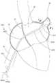
请一并参阅图9和图10,输送鞘管60使用时,输送鞘管60由下腔静脉31进入右心房23,然后再对房间隔27进行穿刺,穿刺后输送鞘管60的远端管633和管身632的一部分进入左心房25,然后通过第一牵引丝641a对第一柔性管6321的远端施加牵引力,第一柔性管6321在第一平面P内弯曲变形,远端管633可由X位置运动至Y位置,然后通过第二牵引丝642a对第二柔性管6323的远端施加牵引力,第二柔性管6323在第二平面Q内弯曲变形,远端管633可由Y位置运动至Z位置。至此,远端管633与左心耳29实现同轴。由于第一平面P和第二平面Q相交,因此通过第一牵引丝641a和第二牵引丝642a可在两个维度上调整远端管633的位置。本实施例的输送鞘管60可以适用于所有解剖形态的心脏,可从两个维度调整输送鞘管60的远端管633的位置,保证远端管633与左心耳29同轴,进而提高输送鞘管60操作的便利性,同时还可以节约手术时间,可降低对患者的伤害。Please refer to Fig. 9 and Fig. 10 together. When thedelivery sheath 60 is in use, thedelivery sheath 60 enters theright atrium 23 from theinferior vena cava 31, and then theinteratrial septum 27 is punctured, and the distal end of thedelivery sheath 60 is punctured. 633 and a part of thetube body 632 enter theleft atrium 25, and then apply traction to the distal end of the firstflexible tube 6321 through thefirst traction wire 641a, the firstflexible tube 6321 bends and deforms in the first plane P, and thedistal tube 633 can be Move from the X position to the Y position, and then apply traction to the distal end of the secondflexible tube 6323 through the second pullingwire 642a, the secondflexible tube 6323 bends and deforms in the second plane Q, and thedistal tube 633 can move from the Y position to the Z position. Location. So far, thedistal tube 633 is coaxial with the leftatrial appendage 29 . Since the first plane P and the second plane Q intersect, the position of thedistal tube 633 can be adjusted in two dimensions through the first pullingwire 641a and the second pullingwire 642a. Thedelivery sheath 60 of this embodiment can be applied to hearts of all anatomical shapes, and the position of thedistal tube 633 of thedelivery sheath 60 can be adjusted from two dimensions to ensure that thedistal tube 633 is coaxial with the leftatrial appendage 29, thereby improving delivery The operation convenience of thesheath tube 60 can also save operation time and reduce the harm to the patient.

在第一柔性管6321与第二柔性管6323之间设有间隔管6322,且该间隔管6322的硬度大于第一柔性管6321和第二柔性管6323的硬度,在操作第二牵引丝642a对第二柔性管6323调弯时,可将第二柔性管6323弯曲时的支点锁定在第二柔性管6323中与间隔管6322相抵的端部(即第二柔性管6323的近端),从而避免第二柔性管6323在调弯时,影响第一柔性管6321的形态,进而可以避免由于第二柔性管6323对第一柔性管6321的形态影响所造成的远端管633无法与左心耳同轴。Aspacer tube 6322 is provided between the firstflexible tube 6321 and the secondflexible tube 6323, and the hardness of thespacer tube 6322 is greater than that of the firstflexible tube 6321 and the secondflexible tube 6323. When the secondflexible tube 6323 is bent, the fulcrum of the secondflexible tube 6323 can be locked at the end of the secondflexible tube 6323 that is against the spacer tube 6322 (ie, the proximal end of the second flexible tube 6323), thereby avoiding When the secondflexible tube 6323 is bent, it affects the shape of the firstflexible tube 6321, thereby avoiding that thedistal tube 633 cannot be coaxial with the left atrial appendage due to the influence of the secondflexible tube 6323 on the shape of the firstflexible tube 6321. .

优选地,第一平面P与第二平面Q相互垂直,第一柔性管6321在第一平面P你调弯,第二柔性管6323在第二平面Q内调弯,可进一步提高输送鞘管60的调弯精度降低手术时间,提高操作的便利性。Preferably, the first plane P and the second plane Q are perpendicular to each other, the firstflexible tube 6321 is bent in the first plane P, and the secondflexible tube 6323 is bent in the second plane Q, so that thedelivery sheath 60 can be further improved. Excellent bending accuracy reduces operation time and improves operation convenience.

在其他实施例中,第一平面P与第二平面Q平行共面,或者,第一平面P与第二平面Q平行。当第一平面P与第二平面Q平行共面时,可以避免穿刺点偏后或者偏前所导致的输送鞘管60无法与左心耳同轴,需要理解地,刺点偏后是指,在房间隔所在的平面内,沿垂直于房间隔的延伸方向,偏向人体的后背,穿刺点偏前的方向与穿刺点偏后的方向相反。当第一平面P与第二平面Q平行时,既可以避免穿刺点偏前或者偏后所导致的输送鞘管60无法与左心耳同轴,还可以避免穿刺点偏高或者偏低所导致的输送鞘管60无法与左心耳同轴,需要理解地,刺点偏低是指,在房间隔所在的平面内,沿房间隔的延伸方向偏向心尖的方向,刺点偏高的方向与刺点偏低的方向相反。In other embodiments, the first plane P and the second plane Q are parallel and coplanar, or the first plane P and the second plane Q are parallel. When the first plane P and the second plane Q are parallel and coplanar, it can avoid thedelivery sheath 60 being unable to be coaxial with the left atrial appendage caused by the puncture point being backward or forward. It should be understood that the puncture point is backward. In the plane where the atrial septum is located, along the extension direction perpendicular to the atrial septum, it is biased toward the back of the human body, and the direction of the puncture point forward is opposite to the direction behind the puncture point. When the first plane P is parallel to the second plane Q, it can avoid the failure of thedelivery sheath 60 to be coaxial with the left atrial appendage caused by the forward or backward puncture point, and also avoid the problem caused by the high or low puncture point. Thedelivery sheath 60 cannot be coaxial with the left atrial appendage. It should be understood that the lower prick point means that in the plane where the atrial septum is located, the extension direction of the atrial septum is biased toward the apex, and the higher direction of the prick point is the same as that of the prick point. Low is in the opposite direction.

第二实施例second embodiment

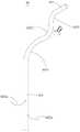
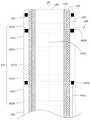
请参阅图11,第二实施例与第一实施例的不同之处在于,管体部分600在自然状态时为弯曲形态。具体地,第一柔性管6321在第一平面P内预塑型成弯曲的管结构,第一柔性管6321近端端部的延伸方向与第一柔性管6321远端端部的延伸方向形成夹角B,该夹角B的范围为45°至90°。Please refer to FIG. 11 , the difference between the second embodiment and the first embodiment is that thetube body portion 600 is in a curved shape in a natural state. Specifically, the firstflexible tube 6321 is preformed into a curved tube structure in the first plane P, and the extending direction of the proximal end of the firstflexible tube 6321 and the extending direction of the distal end of the firstflexible tube 6321 form a clamp. Angle B, the included angle B ranges from 45° to 90°.

第二柔性管6323在自然状态时,第二柔性管6323在第二平面Q内预塑型成弯曲的管结构,第二柔性管6323在近端端部的延伸方向与第二柔性管6323在远端端部的延伸方向形成夹角C,该夹角C的范围为30°至60°。When the secondflexible tube 6323 is in the natural state, the secondflexible tube 6323 is pre-molded into a curved tube structure in the second plane Q, and the extension direction of the proximal end of the secondflexible tube 6323 is in the same direction as the secondflexible tube 6323. The direction of extension of the distal end forms an included angle C, which ranges from 30° to 60°.

输送鞘管60在第一柔性管6321和第二柔性管6323预塑型的基础上,只需要对输送鞘管60的形态进行微调,即可使得输送鞘管60的远端管633与左心耳同轴。On the basis of the pre-molding of the firstflexible tube 6321 and the secondflexible tube 6323, thedelivery sheath 60 only needs to fine-tune the shape of thedelivery sheath 60, so that thedistal tube 633 of thedelivery sheath 60 can be connected to the left atrial appendage. coaxial.

在其他实施例中,第一柔性管6321和第二柔性管6323两者之一,在其自然状态下为弯曲形,即第一柔性管6321近端端部的延伸方向与第一柔性管6321远端端部的延伸方向形成夹角B,该夹角B为45°至90°。或者,第二柔性管6323近端端部的延伸方向与第二柔性管6323远端端部的延伸方向形成夹角C,该夹角C为30°至60°。In other embodiments, one of the firstflexible tube 6321 and the secondflexible tube 6323 is curved in its natural state, that is, the extension direction of the proximal end of the firstflexible tube 6321 is the same as that of the firstflexible tube 6321. The direction of extension of the distal end forms an included angle B, which is 45° to 90°. Alternatively, the extension direction of the proximal end of the secondflexible tube 6323 and the extension direction of the distal end of the secondflexible tube 6323 form an included angle C, and the included angle C is 30° to 60°.

第三实施例third embodiment

请参阅图12,本实施例与第二实施例的不同之处在于,间隔管6322在其自然状态时,在第二平面Q内呈弯曲形态。具体地,可通过预塑型的方式,使得间隔管6322在第二平面Q内呈弯曲形态。间隔管6322与第二柔性管6323的弯曲方向相反,使输送鞘管60在其自然状态下呈“S”型。间隔管6322近端端部的延伸方向与间隔管6322远端端部的延伸方向形成夹角D,夹角D的范围为30°至60°。Please refer to FIG. 12 , the difference between this embodiment and the second embodiment is that thespacer tube 6322 is curved in the second plane Q in its natural state. Specifically, thespacer tube 6322 may be bent in the second plane Q through pre-shaping. Thespacer tube 6322 is bent in the opposite direction to the secondflexible tube 6323, making thedelivery sheath 60 in an "S" shape in its natural state. The extending direction of the proximal end of thespacing tube 6322 and the extending direction of the distal end of thespacing tube 6322 form an included angle D, and the included angle D ranges from 30° to 60°.

第四实施例Fourth embodiment

请参阅图13,本实施例与第一实施例的不同之处在于,管身632还包括过渡管6324,过渡管6324的数量可以是一个,也可以是多个。过渡管6324的硬度小于连接管631、间隔管6322和远端管633的硬度。过渡管6324的硬度大于第一柔性管6321、第二柔性管6323的硬度。过渡管6324的硬度范围为40D至55D。Please refer to FIG. 13 , the difference between this embodiment and the first embodiment is that thetube body 632 further includes atransition tube 6324, and the number of thetransition tube 6324 can be one or more. The hardness of thetransition tube 6324 is less than that of the connectingtube 631 , thespacer tube 6322 and thedistal tube 633 . The hardness of thetransition pipe 6324 is greater than the hardness of the firstflexible pipe 6321 and the secondflexible pipe 6323 . The durometer of thetransition tube 6324 ranges from 40D to 55D.

本实施例中过渡管6324的数量为四个。具体地,远端管633与第二柔性管6323之间设有一过渡管6324,在回收植入器械时,可以避免由于第二柔性管6323与远端管633的硬度相差过大,所导致的输送鞘管60在第二柔性管6323与远端管633相接合处弯折。连接管631与第一柔性管6321之间设有一过渡管6324,在回收植入器械时,可以避免由于第一柔性管6321与连接管631的硬度相差过大,所导致的输送鞘管60在第一柔性管6321与连接管631相接合处弯折。间隔管6322与第一柔性管6321之间设有一过渡管6324,在回收植入器械时,可以避免由于第一柔性管6321与间隔管6322的硬度相差过大,所导致的输送鞘管60在第一柔性管6321与间隔管6322相接合处弯折。间隔管6322与第二柔性管6323之间设有一过渡管6324,在回收植入器械时,可以避免由于第二柔性管6323与间隔管6322的硬度相差过大,所导致的输送鞘管60在第二柔性管6323与间隔管6322相结合处弯折。从而确保输送鞘管60能够安全地回收植入器械。The number oftransition pipes 6324 in this embodiment is four. Specifically, atransition tube 6324 is provided between thedistal tube 633 and the secondflexible tube 6323, which can avoid the excessive difference in hardness between the secondflexible tube 6323 and thedistal tube 633 when recovering the implanted instrument. Thedelivery sheath 60 bends where the secondflexible tube 6323 meets thedistal tube 633 . Atransition tube 6324 is provided between the connectingtube 631 and the firstflexible tube 6321. When recovering the implanted device, thedelivery sheath 60 can be avoided due to the large difference in hardness between the firstflexible tube 6321 and the connectingtube 631. The junction of the firstflexible tube 6321 and the connectingtube 631 is bent. Atransition tube 6324 is provided between thespacer tube 6322 and the firstflexible tube 6321. When recovering the implanted device, thedelivery sheath 60 can be avoided due to the large difference in hardness between the firstflexible tube 6321 and thespacer tube 6322. The junction of the firstflexible tube 6321 and thespacer tube 6322 is bent. Atransition tube 6324 is provided between thespacer tube 6322 and the secondflexible tube 6323. When recovering the implant device, it can avoid the excessive difference in hardness between the secondflexible tube 6323 and thespacer tube 6322. The joint of the secondflexible tube 6323 and thespacer tube 6322 is bent. Thus, it is ensured that thedelivery sheath 60 can safely retrieve the implanted instrument.

当然,在其他实施例中,也可以根据实际需求选择过渡管6324的数量和设置位置,例如过渡管6324的数量为一个。过渡管6324可以设于间隔管6322与第二柔性管6323之间。或者,过渡管6324设于间隔管6322与第一柔性管6321之间。或者,过渡管6324设于连接管631与第一柔性管6321之间。或者,过渡管6324设于远端管633与第二柔性管6323之间。Of course, in other embodiments, the number and location of thetransition tubes 6324 can also be selected according to actual needs, for example, the number oftransition tubes 6324 is one. Thetransition tube 6324 may be disposed between thespacer tube 6322 and the secondflexible tube 6323 . Alternatively, thetransition tube 6324 is disposed between thespacer tube 6322 and the firstflexible tube 6321 . Alternatively, thetransition pipe 6324 is disposed between theconnection pipe 631 and the firstflexible pipe 6321 . Alternatively, thetransition tube 6324 is disposed between thedistal tube 633 and the secondflexible tube 6323 .

第五实施例fifth embodiment

请参阅图14,第五实施例与第四实施例的不同之处在于,本实施例中的输送鞘管60还包括支撑件651,支撑件651的数量至少为一个。支撑件651设于中间层620外表面的外侧,且支撑件651位于外层管630的外表面的内侧。Please refer to FIG. 14 , the difference between the fifth embodiment and the fourth embodiment is that thedelivery sheath 60 in this embodiment further includes asupport member 651 , and the number of thesupport member 651 is at least one. The supportingmember 651 is disposed on the outside of the outer surface of themiddle layer 620 , and the supportingmember 651 is located on the inner side of the outer surface of theouter tube 630 .

本实施例中,支撑件651的数量为多个。第一柔性管6321和第二柔性管6323所在的区间段内均设有支撑件651。在第一柔性管6321所在的区间段内,支撑件651的远端与第一固定结构641b固定连接,使得支撑件651的远端与第一固定结构641b共同形成环形的端面,可以避免支撑件651的远端过于尖锐,在第一柔性管6321由弯曲形态恢复至其自然状态时的形态过程中,即使支撑件651在外层管630内相对滑动也不会刺穿外层管630,进而避免器官组织被刺伤。在第二柔性管6323所在的区间段内,支撑件651的远端与第二固定结构642b固定连接,使得支撑件651的远端与第一固定结构642b共同形成环形的端面,可以避免支撑件651的远端过于尖锐,在第二柔性管6323由弯曲形态恢复至其自然状态时的形态过程中,即使支撑件651在外层管630内相对滑动也不会刺穿外层管630,进而避免器官组织被刺伤。In this embodiment, there aremultiple support members 651 . A supportingmember 651 is provided in the section where the firstflexible pipe 6321 and the secondflexible pipe 6323 are located. In the section where the firstflexible tube 6321 is located, the distal end of thesupport member 651 is fixedly connected to thefirst fixing structure 641b, so that the distal end of thesupport member 651 and thefirst fixing structure 641b jointly form an annular end surface, which can avoid the The distal end of 651 is too sharp, and when the firstflexible tube 6321 returns to its natural state from the bent shape, even if thesupport member 651 slides relatively in theouter tube 630, it will not pierce theouter tube 630, thereby avoiding Organ tissue was stabbed. In the section where the secondflexible tube 6323 is located, the distal end of thesupport member 651 is fixedly connected to thesecond fixing structure 642b, so that the distal end of thesupport member 651 and thefirst fixing structure 642b jointly form an annular end surface, which can avoid the The distal end of 651 is too sharp, and when the secondflexible tube 6323 returns to its natural state from the bent shape, even if thesupport member 651 slides relatively in theouter tube 630, it will not pierce theouter tube 630, thereby avoiding Organ tissue was stabbed.

支撑件651可以为具有超弹性的丝材,支撑件651的丝径小于外层管630的壁厚,以便于将支撑件651设于外层管630和中间层620之间。The supportingmember 651 may be a superelastic wire material, and the wire diameter of the supportingmember 651 is smaller than the wall thickness of theouter tube 630 , so that the supportingmember 651 is arranged between theouter tube 630 and themiddle layer 620 .

支撑件651在第一牵引丝641a的牵拉作用下,可跟随第一柔性管6321在第一平面P内弯曲。支撑件651在第二牵引丝642a的牵拉作用下,跟随第二柔性管6323在第二平面Q内弯曲。由于支撑件651具有超弹性,因此,支撑件651不会阻碍第一柔性管6321和第二柔性管6323的弯曲变形,支撑件651能够增加第一柔性管6321和第二柔性管6323的轴向支撑力,进而可提高输送鞘管60在第一柔性管6321和第二柔性管6323内的轴向支撑力,使得输送鞘管60在具有可调弯性能的基础上,增强其轴向支撑力。使输送鞘管60具有稳定的形态,能够顺利地输送、回收植入器械。Thesupport member 651 can follow the firstflexible tube 6321 to bend in the first plane P under the pulling effect of the first pullingwire 641a. Thesupport member 651 bends in the second plane Q following the secondflexible tube 6323 under the pulling effect of the second pullingwire 642a. Since thesupport 651 has superelasticity, thesupport 651 will not hinder the bending deformation of the firstflexible tube 6321 and the secondflexible tube 6323, and thesupport 651 can increase the axial direction of the firstflexible tube 6321 and the secondflexible tube 6323. The supporting force can further improve the axial supporting force of thedelivery sheath 60 in the firstflexible tube 6321 and the secondflexible tube 6323, so that thedelivery sheath 60 can enhance its axial supporting force on the basis of adjustable bending performance . Thedelivery sheath 60 has a stable shape, so that the implantation device can be delivered and retrieved smoothly.

第一牵引丝641a和第二牵引丝642a的牵拉力撤消后,第一柔性管6321在支撑件651的超弹性作用下恢复至其自然状态时的形态过程中,第二柔性管6323在支撑件651的超弹性作用下其自然状态时的形态过程中,支撑件651的超弹性性能弥补了外层管630的弹性迟滞效应。After the pulling force of the first pullingwire 641a and the second pullingwire 642a is removed, the firstflexible tube 6321 returns to its natural state under the action of the superelasticity of thesupport member 651, and the secondflexible tube 6323 supports The superelastic performance of thesupport member 651 compensates for the elastic hysteresis effect of theouter tube 630 during its natural state under the action of the superelasticity of thesupport member 651 .

在其他实施例中,支撑件651的数量还可以为3个、4个或更多个,输送鞘管60在第一柔性管6321内沿其周向设有多个支撑件651,可进一步提高输送鞘管60弯曲部分的轴向支撑力。输送鞘管60在第二柔性管6323内沿其周向设有多个支撑件651,可进一步提高第二柔性管6323的轴向支撑力。In other embodiments, the number ofsupport members 651 can also be 3, 4 or more, and thedelivery sheath 60 is provided with a plurality ofsupport members 651 along its circumference in the firstflexible tube 6321, which can further improve the delivery sheath. The axial support force of the curved part of thetube 60. Thedelivery sheath 60 is provided with a plurality ofsupports 651 along its circumference in the secondflexible tube 6323 , which can further improve the axial support force of the secondflexible tube 6323 .

在其他实施例中,支撑件651的数量也可以是一个,支撑件651可以设于第二柔性管6323和第一柔性管6321其中之一所在的区间段内。In other embodiments, the number of thesupport member 651 may also be one, and thesupport member 651 may be disposed in the section where one of the secondflexible pipe 6323 and the firstflexible pipe 6321 is located.

其他实施例中的支撑件661也可以是片材。支撑件661的壁厚小于外层管630的壁厚以使得支撑件661更易嵌入外层管630内。The supporting member 661 in other embodiments may also be a sheet. The wall thickness of the support member 661 is smaller than that of theouter tube 630 so that the support member 661 is more easily embedded in theouter tube 630 .

第六实施例Sixth embodiment

请参阅图15,第六实施例与第五实施例的不同之处在于,本实施例中的支撑件671为螺旋体,支撑件671套设于中间层620外表面的外侧,且支撑件671位于外层管630的外表面的内侧,支撑件671由具有超弹性的材料制成,支撑件671包括近端段6711、螺旋延伸段6712和远端段6713,螺旋延伸段6712位于近端段6711与远端段6713之间。Please refer to Fig. 15, the difference between the sixth embodiment and the fifth embodiment is that thesupport member 671 in this embodiment is a spiral body, thesupport member 671 is sleeved on the outside of the outer surface of themiddle layer 620, and thesupport member 671 is located Inside the outer surface of theouter tube 630, thesupport member 671 is made of superelastic material. Thesupport member 671 includes aproximal section 6711, ahelical extension section 6712 and adistal section 6713. Thehelical extension section 6712 is located at theproximal section 6711. and between thedistal segment 6713.

支撑件671的近端段6711为一封闭的环状体,近端段6711的远端与螺旋延伸段6712相连。Theproximal section 6711 of thesupport member 671 is a closed annular body, and the distal end of theproximal section 6711 is connected with thehelical extension section 6712 .

支撑件671的远端段6713为一封闭的环状体。第一连接孔6411a、第二连接孔6411b、第三连接孔6411c可不设于固定结构上,而设于支撑件671的远端段6713侧壁上,可以避免第一牵引丝641a和第二牵引丝642a在使用过程中出现应力集中,还可以节约一个固定结构的材料,降低成本。Thedistal section 6713 of thesupport member 671 is a closed ring. Thefirst connection hole 6411a, thesecond connection hole 6411b, and thethird connection hole 6411c may not be arranged on the fixed structure, but on the side wall of thedistal end section 6713 of thesupport member 671, which can avoid the first pullingwire 641a and the second pulling Stress concentration occurs in thewire 642a during use, which can also save the material of a fixed structure and reduce the cost.

螺旋延伸段6712具有延伸体67121,延伸体67121可由激光在螺旋延伸段6712内的管材上切割所形成,延伸体67121在螺旋延伸段内6712螺旋延伸。Thespiral extension section 6712 has anextension body 67121, which can be formed by laser cutting on the pipe in thespiral extension section 6712, and theextension body 67121 spirally extends in thespiral extension section 6712.

沿平行于支撑件671的中心轴线6714方向切割支撑件671的一侧壁,且沿支撑件671的径向展开切割后的支撑件671,延伸体67121与支撑件671的中心轴线6714形成的夹角E的范围为0°至90°。可以在保证支撑件671可调弯的情况下,提供足够的轴向支撑力。优选地,延伸体67121与支撑件671的中心轴线6714形成的夹角E的范围为60°至90°,在输送鞘管调弯过程中,提高输送鞘管60的抗折性能,同时提高输送鞘管60的轴向支撑力。延伸体67121的轴向厚度L为0.05mm-3.0mm,在输送鞘管调弯过程中,提高输送鞘管的抗折性能,同时提高输送鞘管的轴向支撑力。优先地,延伸体67121的轴向厚度L为0.1mm-0.5mm。相邻两延伸体67121的间隙D为0.05mm-3.0mm。优先地,相邻两延伸体67121的间隙D为0.1mm-0.5mm,在输送鞘管调弯过程中,提高输送鞘管的抗折性能,同时提高输送鞘管的轴向支撑力。可以理解地,延伸体67121与支撑件671的中心轴线形成的夹角E,夹角E越小,相邻两延伸体67121的间隙D越大,支撑件671可调弯性能越好,夹角E越大,相邻两延伸体67121的间隙D越小,支撑件671的轴向支撑力更大。Cut the side wall of thesupport member 671 along the direction parallel to thecentral axis 6714 of thesupport member 671, and expand thecut support member 671 along the radial direction of thesupport member 671, the clamp formed by theextension body 67121 and thecentral axis 6714 of thesupport member 671 Angle E ranges from 0° to 90°. Sufficient axial supporting force can be provided under the condition that thesupport member 671 can be adjusted to be bent. Preferably, the angle E formed by theextension body 67121 and thecentral axis 6714 of thesupport member 671 is in the range of 60° to 90°. During the bending process of the delivery sheath, the bending resistance of thedelivery sheath 60 can be improved, and the delivery can be improved at the same time. The axial support force of thesheath tube 60. The axial thickness L of theextension body 67121 is 0.05mm-3.0mm, which improves the bending resistance of the delivery sheath and the axial support force of the delivery sheath during the bending adjustment process of the delivery sheath. Preferably, the axial thickness L of theextension body 67121 is 0.1mm-0.5mm. The gap D between twoadjacent extension bodies 67121 is 0.05mm-3.0mm. Preferably, the gap D between twoadjacent extension bodies 67121 is 0.1mm-0.5mm, so as to improve the bending resistance of the delivery sheath and the axial support force of the delivery sheath during the bending adjustment process of the delivery sheath. It can be understood that the angle E formed by theextension body 67121 and the central axis of thesupport member 671, the smaller the angle E, the larger the gap D between twoadjacent extension bodies 67121, the better the adjustable bending performance of thesupport member 671, the better the angle E The larger E is, the smaller the gap D between twoadjacent extension bodies 67121 is, and the axial supporting force of thesupport member 671 is greater.

第七实施例Seventh embodiment

请参阅图16和图17,第七实施例与第八实施例的不同之处在于,本实施例中的支撑件681为龙骨结构。Please refer to FIG. 16 and FIG. 17 , the difference between the seventh embodiment and the eighth embodiment is that thesupport member 681 in this embodiment is a keel structure.

本实施例中,第一柔性管6321和第二柔性管6323所在的区间段均设有支撑件681,支撑件681包括一龙骨6811和多个骨架6812,多个骨架6812沿龙骨6811的轴向(长度方向)间隔排列,多个骨架6812的两端分别与龙骨6811的两侧相连,龙骨6811与多个骨架6812共同形成一环形的收容空间6813,中间层620(即输送鞘管60的管壁)收容于收容空间6813内以使得支撑件681套设于中间层620外(即支撑件681设于输送鞘管60中)。支撑件681的远端受牵引力作用时,各骨架6812彼此间隔排列,使得各骨架6812之间具有变形的空间,可降低支撑件681弯曲阻力,以保证支撑件681不阻碍第一柔性管6321和第二柔性管6323的调弯,同时,各骨架6812彼此间隔排列,还可供外层管630的高分子材料嵌入,可避免支撑件681沿外层管630轴向滑动,进而可避免支撑件681的近端刺穿外层管630的高分子材料。并且,由于龙骨6811可提供轴向支撑力,因此,支撑件681可以提高第一柔性管6321和第二柔性管6323的轴向支撑力,避免输送鞘管60折弯。In this embodiment, the section where the firstflexible pipe 6321 and the secondflexible pipe 6323 are located is provided with asupport member 681, thesupport member 681 includes akeel 6811 and a plurality ofskeletons 6812, and the plurality ofskeletons 6812 are along the axial direction of the keel 6811 (in the length direction) are arranged at intervals, the two ends of the plurality ofskeletons 6812 are respectively connected to the two sides of thekeel 6811, thekeel 6811 and the plurality ofskeletons 6812 jointly form anannular receiving space 6813, the middle layer 620 (that is, the tube of thedelivery sheath 60 wall) is accommodated in the receivingspace 6813 so that thesupport member 681 is sheathed outside the intermediate layer 620 (that is, thesupport member 681 is disposed in the delivery sheath 60 ). When the distal end of thesupport member 681 is subjected to traction force, theskeletons 6812 are spaced apart from each other, so that there is a space for deformation between theskeletons 6812, which can reduce the bending resistance of thesupport member 681, so as to ensure that thesupport member 681 does not hinder the firstflexible tube 6321 and The bending of the secondflexible tube 6323, at the same time, theskeletons 6812 are arranged at intervals, which can also be embedded in the polymer material of theouter tube 630, which can prevent thesupport 681 from sliding axially along theouter tube 630, thereby avoiding the support The proximal end of 681 pierces the polymeric material ofouter tube 630 . Moreover, since thekeel 6811 can provide axial support force, thesupport member 681 can increase the axial support force of the firstflexible tube 6321 and the secondflexible tube 6323 to avoid bending of thedelivery sheath 60 .

当然,在其他实施例中,也可根据实际需求选择支撑件681所在的区间段,例如,仅在第一柔性管6321所在的区间段内设置支撑件681。或者,仅在第二柔性管6323所在的区间段内设置支撑件681。Of course, in other embodiments, the interval where thesupport member 681 is located may also be selected according to actual needs, for example, thesupport member 681 is only provided in the interval where the firstflexible tube 6321 is located. Alternatively, thesupport member 681 is only provided in the section where the secondflexible tube 6323 is located.

多个骨架6812中最远端的骨架6812具有远端端面68121,龙骨6811的远端端部与远端端面68121平齐,或者,龙骨6811的远端端部位于远端端面68121的近端侧。可以避免在输送鞘管60调弯时,龙骨6811的远端刺穿外层管630。The mostdistal frame 6812 of the plurality offrames 6812 has adistal end face 68121 with the distal end of thekeel 6811 flush with or proximal to thedistal end face 68121 . This can prevent the distal end of thekeel 6811 from piercing theouter tube 630 when thedelivery sheath 60 is bent.

多个骨架6812中最近端的骨架6812具有近端端面68122,龙骨6811的近端端部与近端端面68122平齐,或者,龙骨6811的近端端部位于近端端面68122的远端侧。可以避免在输送鞘管60调弯时,龙骨6811的远端刺穿外层管630。The mostproximal backbone 6812 of the plurality ofbackbones 6812 has aproximal end face 68122 with the proximal end of thekeel 6811 flush with or on the distal side of theproximal end face 68122 . This can prevent the distal end of thekeel 6811 from piercing theouter tube 630 when thedelivery sheath 60 is bent.

支撑件681的远端设有上述的第一连接孔6411a、第二连接孔6411b和第三连接孔6411c,可以避免第一牵引丝641a和第二牵引丝642a在使用过程中出现应力集中,还可以节约一个固定结构的材料,降低成本。具体地,第一连接孔6411a、第二连接孔6411b和第三连接孔6411c可设于龙骨6811的远端。或者,第一连接孔6411a、第二连接孔6411b和第三连接孔6411c可设于支撑件681远端的骨架6812上。The distal end of thesupport member 681 is provided with the above-mentioned first connectinghole 6411a, second connectinghole 6411b and third connectinghole 6411c, which can avoid the stress concentration of the first pullingwire 641a and the second pullingwire 642a during use, and also The material of a fixed structure can be saved and the cost can be reduced. Specifically, thefirst connection hole 6411a, thesecond connection hole 6411b and thethird connection hole 6411c may be disposed at the distal end of thekeel 6811 . Alternatively, thefirst connection hole 6411 a , thesecond connection hole 6411 b and thethird connection hole 6411 c may be disposed on theskeleton 6812 at the distal end of thesupport member 681 .

支撑件681安装于第一柔性管6321内时,支撑件681的长度L2与第一柔性管6321的长度相等,支撑件681安装于第二柔性管6323内时,支撑件681的长度L2与第二柔性管6323的长度相等。龙骨6811的宽度L1小于任一骨架6812周长L3的一半,即L1<L3/2。如此,使龙骨6811的硬度适中,在提高输送鞘管60轴向支撑力的同时,保证输送鞘管60可以在第一牵引丝641a、第二牵引丝642a带动下弯曲变形,支撑件681可由具有超弹性的镍钛合金管材经过激光切割而成。When thesupport member 681 is installed in the firstflexible pipe 6321, the length L2 of thesupport member 681 is equal to the length of the firstflexible pipe 6321; when thesupport member 681 is installed in the secondflexible pipe 6323, the length L2 of thesupport member 681 is equal to the length The lengths of the twoflexible tubes 6323 are equal. The width L1 of thekeel 6811 is less than half of the perimeter L3 of anyskeleton 6812, ie L1<L3/2. In this way, the hardness of thekeel 6811 is moderate, and while increasing the axial support force of thedelivery sheath 60, it is ensured that thedelivery sheath 60 can be bent and deformed under the driving of thefirst drawing wire 641a and thesecond drawing wire 642a, and thesupport member 681 can be formed by The ultra-elastic Nitinol tubing is laser cut.

第八实施例Eighth embodiment

请参阅图18,第八实施例与第七实施例的不同之处在于,龙骨691上还设有镂空结构6913,外层管630的弹性尼龙可进入镂空结构6913内,增大龙骨691与外层管630的接触面积,可以提高支撑件691与外层管630的弹性尼龙的结合强度,以及提高支撑件691疲劳寿命,延长使用周期。镂空结构6913的形状可以为矩形、圆形、椭圆形、方形、三角形、菱形等。优选地,镂空结构6913的形状为菱形。镂空结构6913的形状为菱形,提高支撑件691的可弯曲变形能力,进而降低支撑件691对第一柔性管6321和第二柔性管6323弯曲变形的阻碍作用。龙骨6911与骨架6912相接合的部位设有凹槽6914,使得龙骨6911在弯曲变形时其材料具有变形空间,增大支撑件691弯曲时的顺应性。Please refer to Fig. 18, the difference between the eighth embodiment and the seventh embodiment is that thekeel 691 is also provided with ahollow structure 6913, and the elastic nylon of theouter tube 630 can enter thehollow structure 6913 to increase the distance between thekeel 691 and the outer shell. The contact area of thelayer tube 630 can increase the bonding strength between thesupport member 691 and the elastic nylon of theouter layer tube 630, improve the fatigue life of thesupport member 691, and prolong the service life. The shape of thehollow structure 6913 can be rectangle, circle, ellipse, square, triangle, rhombus and so on. Preferably, the shape of thehollow structure 6913 is rhombus. The shape of thehollow structure 6913 is a rhombus, which improves the bending and deformation capability of thesupport member 691 , thereby reducing the resistance of thesupport member 691 to the bending deformation of the firstflexible tube 6321 and the secondflexible tube 6323 . Agroove 6914 is provided at the junction of thekeel 6911 and theframe 6912, so that the material of thekeel 6911 has a deformation space when it is bent and deformed, and the compliance of thesupport member 691 is increased when it is bent.

骨架6912包括相对设置于龙骨6911两侧的第一连接部69121和第二连接部69123,第一连接部69121与第二连接部69123关于龙骨6911的轴线对称。第一连接部69121的自由端设有卡扣69122。优选地,卡扣69122为T形。第二连接部69123的自由端设有卡槽69124,卡槽69124具有弹性,卡槽69124受外力作用其槽宽可在一定范围内变大。也就是说,受外力作用,卡槽69124沿龙骨6912轴线的尺寸可一定程度的变大。卡槽69124的形状与卡扣69122相配合,以使得卡槽能69124够容纳卡扣69122,并且实现卡槽69124与卡扣69122的卡接配合形成收容空间6813。卡扣69122插入卡槽69124以使得第一连接部69121与第二连接部69123卡接。由于卡槽69124具有弹性,卡槽69124受外力作用其槽宽可再一定范围内变大,卡扣69122在卡槽69124内可沿卡槽69124的长度方向滑动,即骨架6912的周长在一定范围内可变,进而使得支撑件691可以适用多种管径的输送鞘管60。Theframe 6912 includes a first connectingportion 69121 and a second connectingportion 69123 disposed on opposite sides of thekeel 6911 , and the first connectingportion 69121 and the second connectingportion 69123 are symmetrical about the axis of thekeel 6911 . The free end of the first connectingportion 69121 is provided with abuckle 69122 . Preferably, thebuckle 69122 is T-shaped. The free end of the second connectingpart 69123 is provided with aslot 69124, theslot 69124 is elastic, and the slot width of theslot 69124 can be enlarged within a certain range under the action of external force. That is to say, under the action of external force, the size of the lockinggroove 69124 along the axis of thekeel 6912 can be enlarged to a certain extent. The shape of theslot 69124 matches thebuckle 69122, so that theslot 69124 can accommodate thebuckle 69122, and the snap fit between theslot 69124 and thebuckle 69122 forms a receivingspace 6813. Thebuckle 69122 is inserted into theslot 69124 so that the first connectingportion 69121 is engaged with the second connectingportion 69123 . Due to the elasticity of theslot 69124, the slot width of theslot 69124 can be enlarged within a certain range under the action of an external force, and thebuckle 69122 can slide along the length direction of theslot 69124 in theslot 69124, that is, the circumference of theskeleton 6912 is within a certain range. The range is variable, so that thesupport member 691 can be applied todelivery sheaths 60 of various diameters.

第九实施例Ninth embodiment

请参阅图19,第九实施例与第八实施例的不同之处在于,本实施例的支撑件711还包括多个近端加强筋7115、远端加强筋7116及中间加强筋7117,近端加强筋7115、远端加强筋7116及中间加强筋7117均沿龙骨7111的长度方向延伸延伸排布,近端加强筋7115、远端加强筋7116及中间加强筋7117均成对设置。在支撑件711的近端相邻两骨架7112之间设有一对近端加强筋7115,该对近端加强筋7115关于支撑件711的纵向中心轴7118对称。在支撑件711的远端相邻两骨架7112之间设有一对远端加强筋7116,该对远端加强筋7116关于支撑件711的纵向中心轴7118对称。沿支撑件711的长度方向,在近端加强筋7115与远端近端加强筋7116之间的相邻的两骨架7112之间设有中间加强筋7117,中间加强筋7117成对分布于纵向中心轴线7118的两侧,成对设置的中间加强筋7117关于纵向中心轴线7118对称,近端加强筋7115、远端加强筋7116及中间加强筋7117可增加支撑件的轴向支撑力,进而增加输送鞘管60的轴向支撑力。支撑件711关于其横向中心轴7119对称。Please refer to Fig. 19, the difference between the ninth embodiment and the eighth embodiment is that thesupport member 711 of this embodiment also includes a plurality of proximal reinforcingribs 7115, distal reinforcingribs 7116 andmiddle reinforcing ribs 7117, the proximal Thereinforcement ribs 7115, thedistal reinforcement ribs 7116 and themiddle reinforcement ribs 7117 are all extended and arranged along the length direction of thekeel 7111, and theproximal reinforcement ribs 7115, thedistal reinforcement ribs 7116 and themiddle reinforcement ribs 7117 are arranged in pairs. A pair of near-end reinforcing ribs 7115 is arranged between twoadjacent frameworks 7112 at the proximal end of thesupport member 711 , and the pair of proximal reinforcingribs 7115 are symmetrical about the longitudinalcentral axis 7118 of thesupport member 711 . A pair of distal reinforcingribs 7116 is arranged between twoadjacent skeletons 7112 at the distal end of thesupport member 711 , and the pair of distal reinforcingribs 7116 are symmetrical about the longitudinalcentral axis 7118 of thesupport member 711 . Along the length direction of thesupport member 711,intermediate ribs 7117 are arranged between the adjacent twoskeletons 7112 between the proximal reinforcingrib 7115 and the distalproximal reinforcing rib 7116, and the intermediate reinforcingribs 7117 are distributed in pairs in the longitudinal center On both sides of theaxis 7118, themiddle ribs 7117 arranged in pairs are symmetrical about the longitudinalcentral axis 7118. Theproximal ribs 7115, thedistal ribs 7116 and themiddle ribs 7117 can increase the axial support force of the support, thereby increasing the transport The axial support force of thesheath tube 60. Thesupport 711 is symmetrical about its transversecentral axis 7119 .

沿支撑件711的宽度方向,近端加强筋7115、远端加强筋7116及中间加强筋7117均与龙骨7111间距设置。具体地,近端加强筋7115到纵向中心轴7118的距离与远端加强筋7116到纵向中心轴7118的距离相等,均为D1。中间加强筋7117到纵向中心轴7118的距离为D2,D1大于或等于D2。Along the width direction of thesupport member 711 , theproximal reinforcement rib 7115 , thedistal reinforcement rib 7116 and themiddle reinforcement rib 7117 are all spaced apart from thekeel 7111 . Specifically, the distance from the proximal reinforcingrib 7115 to the longitudinalcentral axis 7118 is equal to the distance from the distal reinforcingrib 7116 to the longitudinalcentral axis 7118, both being D1. The distance from themiddle rib 7117 to the longitudinalcentral axis 7118 is D2, and D1 is greater than or equal to D2.

本实施例中,近端加强筋7115、远端加强筋7116及中间加强筋7117均与龙骨7111间距设置,D1大于或等于D2,在增大支撑件711的轴向支撑力的同时,增大支撑件711弯曲时的顺应性,进而减小支撑件711调弯时所需牵引力。成对设置的近端加强筋7115、远端加强筋7116及中间加强筋7117均关于纵向中心轴7118对称,以及支撑件711关于横向中心轴线7119对称,也可在增大支撑件711的轴向支撑力的同时,增大支撑件711弯曲时的顺应性,进而减小支撑件711调弯时所需牵引力。In this embodiment, the proximal reinforcingrib 7115, the distal reinforcingrib 7116, and themiddle reinforcing rib 7117 are arranged at a distance from thekeel 7111, and D1 is greater than or equal to D2. While increasing the axial support force of thesupport member 711, the The compliance of thesupport member 711 when it is bent can further reduce the traction force required when thesupport member 711 is adjusted to bend. Theproximal ribs 7115,distal ribs 7116 andmiddle ribs 7117 arranged in pairs are all symmetrical about the longitudinalcentral axis 7118, and thesupport 711 is symmetrical about the transversecentral axis 7119, and the axial direction of thesupport 711 can also be enlarged. While supporting the force, the compliance of thesupport member 711 when bending is increased, thereby reducing the required traction force when thesupport member 711 is bent.

当然,在其他实施例中,近端加强筋7115到纵向中心轴7118的距离与远端加强筋7116到纵向中心轴7118的距离不相等,近端加强筋7115到纵向中心轴7118的距离与远端加强筋7116到纵向中心轴7118的距离均大于中间加强筋7117到纵向中心轴7118的距离,也可在增大支撑件711的轴向支撑力的同时,增大支撑件711弯曲时的顺应性,进而减小支撑件711调弯时所需牵引力。Of course, in other embodiments, the distance from the proximal reinforcingrib 7115 to the longitudinalcentral axis 7118 is not equal to the distance from the distal reinforcingrib 7116 to the longitudinalcentral axis 7118, and the distance from the proximal reinforcingrib 7115 to the longitudinalcentral axis 7118 is the same as the distance from the distal reinforcingrib 7115 to the longitudinalcentral axis 7118. The distance from theend reinforcing rib 7116 to the longitudinalcentral axis 7118 is greater than the distance from themiddle reinforcing rib 7117 to the longitudinalcentral axis 7118, which can also increase the axial support force of the supportingmember 711 while increasing the compliance of the supportingmember 711 when bending performance, thereby reducing the traction force required when thesupport member 711 is turned.

第十实施例Tenth embodiment

本实施例提供一种医疗器械,包括上述实施例中的输送鞘管。This embodiment provides a medical device, including the delivery sheath in the above embodiment.

以上所述实施例的各技术特征可以进行任意的组合,为使描述简洁,未对上述实施例中的各个技术特征所有可能的组合都进行描述,然而,只要这些技术特征的组合不存在矛盾,都应当认为是本说明书记载的范围。The technical features of the above-mentioned embodiments can be combined arbitrarily. To make the description concise, all possible combinations of the technical features in the above-mentioned embodiments are not described. However, as long as there is no contradiction in the combination of these technical features, should be considered as within the scope of this specification.

以上所述实施例仅表达了本发明的几种实施方式,其描述较为具体和详细,但并不能因此而理解为对发明专利范围的限制。应当指出的是,对于本领域的普通技术人员来说,在不脱离本发明构思的前提下,还可以做出若干变形和改进,这些都属于本发明的保护范围。因此,本发明专利的保护范围应以所附权利要求为准。The above-mentioned embodiments only express several implementation modes of the present invention, and the descriptions thereof are relatively specific and detailed, but should not be construed as limiting the patent scope of the invention. It should be noted that those skilled in the art can make several modifications and improvements without departing from the concept of the present invention, and these all belong to the protection scope of the present invention. Therefore, the protection scope of the patent for the present invention should be based on the appended claims.

Claims (10)

Translated fromChinese
1.一种输送鞘管,包括管体部分,其特征在于,所述管体部分包括:1. A delivery sheath comprising a body part, characterized in that the body part comprises:外层管,包括连接管、管身及远端管,所述管身位于所述连接管与所述远端管之间,所述管身包括第一柔性管、间隔管以及第二柔性管,所述间隔管设于所述第一柔性管的远端与所述第二柔性管的近端之间,所述连接管的硬度大于所述第一、第二柔性管的硬度,所述间隔管的硬度大于所述第一、第二柔性管的硬度,远端管的硬度大于所述第一柔性管和第二柔性管的硬度,及The outer tube includes a connecting tube, a tube body and a distal tube, the tube body is located between the connecting tube and the distal tube, and the tube body includes a first flexible tube, a spacer tube and a second flexible tube , the spacer tube is arranged between the distal end of the first flexible tube and the proximal end of the second flexible tube, the hardness of the connecting tube is greater than the hardness of the first and second flexible tubes, the The hardness of the spacer tube is greater than the hardness of the first and second flexible tubes, the hardness of the distal tube is greater than the hardness of the first flexible tube and the second flexible tube, and牵引结构,所述牵引结构包括第一牵引丝和第二牵引丝,所述第一牵引丝与所述第一柔性管的相连,所述第二牵引丝与所述第二柔性管的相连,所述第一牵引丝和所述第二牵引丝均在所述外层管内延伸,且所述第一牵引丝的自由端和所述第二牵引丝的自由端均延伸出所述连接管的近端,所述第一牵引丝相对所述管身可滑动,并能够带动所述第一柔性管在第一平面内产生弯曲,所述第二牵引丝相对所述管身可滑动,能够带动所述第二柔性管在第二平面内产生弯曲,所述第一平面与所述第二平面相交、平行或共面。a traction structure, the traction structure includes a first traction wire and a second traction wire, the first traction wire is connected to the first flexible pipe, and the second traction wire is connected to the second flexible pipe, Both the first drawing wire and the second drawing wire extend inside the outer tube, and the free ends of the first drawing wire and the free ends of the second drawing wire both extend out of the connecting pipe At the proximal end, the first pulling wire is slidable relative to the tube body and can drive the first flexible tube to bend in the first plane, and the second pulling wire is slidable relative to the tube body and can drive The second flexible tube is bent in a second plane, and the first plane is intersecting, parallel or coplanar with the second plane.2.如权利要求1所述的输送鞘管,其特征在于,所述第一柔性管的硬度大于或等于所述第二柔性管的硬度。2. The delivery sheath of claim 1, wherein the stiffness of the first flexible tube is greater than or equal to the stiffness of the second flexible tube.3.如权利要求1所述的输送鞘管,其特征在于,所述管身还包括过渡管,3. The delivery sheath according to claim 1, wherein the tube body further comprises a transition tube,所述过渡管设于所述间隔管与所述第一柔性管之间,所述过渡管的硬度小于所述间隔管的硬度,所述过渡管的硬度大于所述第一柔性管的硬度,The transition pipe is arranged between the spacer pipe and the first flexible pipe, the hardness of the transition pipe is smaller than the hardness of the spacer pipe, and the hardness of the transition pipe is greater than the hardness of the first flexible pipe,或,所述过渡管设于所述间隔管与所述第二柔性管之间,所述过渡管的硬度小于所述间隔管的硬度,所述过渡管的硬度大于所述第二柔性管的硬度,Or, the transition pipe is arranged between the spacer pipe and the second flexible pipe, the hardness of the transition pipe is less than that of the spacer pipe, and the hardness of the transition pipe is greater than that of the second flexible pipe. hardness,或,所述过渡管设于所述连接管与所述第一柔性管之间,所述过渡管的硬度小于所述连接管的硬度,所述过渡管的硬度大于所述第一柔性管的硬度,Or, the transition pipe is arranged between the connecting pipe and the first flexible pipe, the hardness of the transition pipe is smaller than that of the connecting pipe, and the hardness of the transition pipe is greater than that of the first flexible pipe. hardness,或,所述过渡管设于所述远端管与所述第二柔性管之间,所述过渡管的硬度小于所述远端管的硬度,所述过渡管的硬度大于所述第二柔性管的硬度。Or, the transition tube is arranged between the distal tube and the second flexible tube, the hardness of the transition tube is less than that of the distal tube, and the hardness of the transition tube is greater than that of the second flexible tube. Tube hardness.4.如权利要求1所述的输送鞘管,其特征在于,所述第一平面与所述第二平面相互垂直。4. The delivery sheath of claim 1, wherein the first plane and the second plane are perpendicular to each other.5.如权利要求1所述的输送鞘管,其特征在于,所述牵引结构还包括固定于所述管身中的第一固定结构和/或第二固定结构,所述第一固定结构设于所述第一柔性管的远端,所述第二固定结构设于所述第二柔性管的远端,所述第一固定结构和/或所述第二固定结构的侧壁开设有第一连接孔、第二连接孔及第三连接孔,沿所述第一固定结构和/或所述第二固定结构的圆周方向,所述第二连接孔位于所述第一连接孔和所述第三连接孔之间,所述第一连接孔、所述第二连接孔和所述第三连接孔的孔心的连线可形成三角形;所述三角形中在所述第二连接孔的孔心所形成的内角为钝角,所述第一牵引丝依次穿过所述第一固定结构的所述第一连接孔、所述第二连接孔、所述第三连接孔以与所述第一固定结构相连,和/或,所述第二牵引丝依次穿过所述第二固定结构的所述第一连接孔、所述第二连接孔、所述第三连接孔以与所述第二固定结构相连。5. The delivery sheath according to claim 1, wherein the traction structure further comprises a first fixing structure and/or a second fixing structure fixed in the tube body, and the first fixing structure is set At the far end of the first flexible tube, the second fixing structure is arranged at the far end of the second flexible tube, and the side wall of the first fixing structure and/or the second fixing structure is provided with a first A connecting hole, a second connecting hole and a third connecting hole, along the circumferential direction of the first fixing structure and/or the second fixing structure, the second connecting hole is located between the first connecting hole and the Between the third connecting holes, the connecting line of the center of the first connecting hole, the second connecting hole and the third connecting hole can form a triangle; The inner angle formed by the heart is an obtuse angle, and the first pulling wire passes through the first connection hole, the second connection hole, and the third connection hole of the first fixing structure in order to connect with the first fixed structure, and/or, the second drawing wire passes through the first connection hole, the second connection hole, and the third connection hole of the second fixed structure in order to connect with the second Fixed structure connected.6.如权利要求1所述的输送鞘管,其特征在于,所述管身还包括设于所述管身中的至少一个支撑件,当所述支撑件的数量为一个时,所述支撑件设于所述第一柔性管或所述第二柔性管所在的区间段内,当所述支撑件的数量为多个时,所述第一柔性管和所述第二柔性管所在的区间段内均设有所述支撑件。6. The delivery sheath according to claim 1, wherein the tube body further comprises at least one support provided in the tube body, and when the number of the support is one, the support parts are arranged in the section where the first flexible pipe or the second flexible pipe is located, and when the number of the support members is multiple, the section where the first flexible pipe and the second flexible pipe are located The supports are provided in each section.7.如权利要求6所述的输送鞘管,其特征在于,所述支撑件包括沿螺旋线延伸的延伸体,沿平行于所述支撑件的中心轴线方向切割所述支撑件的一侧壁后,再沿所述支撑件的径向展开切割后的所述支撑件,所述延伸体与所述支撑件的中心轴线形成的夹角E的范围为60°至90°。7. The delivery sheath according to claim 6, wherein the support member comprises an extension body extending along a helix, and a side wall of the support member is cut along a direction parallel to the central axis of the support member Afterwards, the cut support member is deployed along the radial direction of the support member, and the angle E formed by the extension body and the central axis of the support member ranges from 60° to 90°.8.如权利要求1所述的输送鞘管,其特征在于,所述第一柔性管在自然状态下为弯曲形态,所述第一柔性管近端端部的延伸方向与所述第一柔性管远端端部的延伸方向形成夹角B,所述夹角B的范围为45°至90°。8. The delivery sheath according to claim 1, wherein the first flexible tube is in a curved shape in a natural state, and the extension direction of the proximal end of the first flexible tube is in the same direction as the first flexible tube. The direction of extension of the distal end of the tube forms an included angle B ranging from 45° to 90°.9.如权利要求1所述的输送鞘管,其特征在于,所述间隔管在其自然状态下为直线形态或弯曲形态,当所述间隔管在其自然状态下弯曲形态时,所述间隔管在所述第二平面内呈弯曲形态,所述间隔管的弯曲方向与所述第二柔性管的弯曲方向相反,当所述间隔管在其自然状态下为直线形态时,所述间隔管在所述第二平面内呈直线形态。9. The delivery sheath according to claim 1, wherein the spacer tube is in a straight line or a curved shape in its natural state, and when the spacer tube is in a curved shape in its natural state, the spacer The tube is curved in the second plane, and the bending direction of the spacer tube is opposite to that of the second flexible tube. When the spacer tube is straight in its natural state, the spacer tube It is in the form of a straight line in the second plane.10.一种医疗器械,其特征在于,所述医疗器械包括如权利要求1至9中任意一项所述的输送鞘管。10. A medical device, characterized in that the medical device comprises the delivery sheath according to any one of claims 1-9.
CN201911301098.3A2019-12-172019-12-17Delivery sheath and medical instrumentActiveCN112971901B (en)

Priority Applications (5)

Application NumberPriority DateFiling DateTitle
CN201911301098.3ACN112971901B (en)2019-12-172019-12-17Delivery sheath and medical instrument
CA3162237ACA3162237A1 (en)2019-12-172020-11-06Delivery sheath and medical device
PCT/CN2020/126982WO2021120917A1 (en)2019-12-172020-11-06Delivery sheath and medical device
EP20900879.6AEP4079367A4 (en)2019-12-172020-11-06Delivery sheath and medical device
US17/786,816US20230028589A1 (en)2019-12-172020-11-06Delivery sheath and medical device

Applications Claiming Priority (1)

Application NumberPriority DateFiling DateTitle
CN201911301098.3ACN112971901B (en)2019-12-172019-12-17Delivery sheath and medical instrument

Publications (2)

Publication NumberPublication Date
CN112971901A CN112971901A (en)2021-06-18
CN112971901Btrue CN112971901B (en)2023-01-03

Family

ID=76342100

Family Applications (1)

Application NumberTitlePriority DateFiling Date
CN201911301098.3AActiveCN112971901B (en)2019-12-172019-12-17Delivery sheath and medical instrument

Country Status (1)

CountryLink
CN (1)CN112971901B (en)

Families Citing this family (8)

* Cited by examiner, † Cited by third party
Publication numberPriority datePublication dateAssigneeTitle
CN113558681B (en)*2021-07-262022-07-15宁波市第一医院Bendable left atrial appendage occluder conveying system and using method
CN115715838A (en)*2021-08-242023-02-28先健科技(深圳)有限公司Medical instrument capable of adjusting bending
CN114082075B (en)*2021-09-282023-07-18四川大学华西医院 An auxiliary bending control sheath
CN116328152A (en)*2021-12-152023-06-27微创优通医疗科技(嘉兴)有限公司Balloon catheter
CN114886498A (en)*2022-04-262022-08-12骨圣元化机器人(深圳)有限公司Bone drill device
CN119606493B (en)*2023-09-142025-09-19杭州德晋医疗科技有限公司 Transseptal puncture system for easy positioning
CN118787836A (en)*2024-08-222024-10-18无忧跳动医疗科技(深圳)有限公司 Delivery Sheath
CN118902361A (en)*2024-10-092024-11-08湖南省华芯医疗器械有限公司Traction rope assembly, insertion part and endoscope

Family Cites Families (3)

* Cited by examiner, † Cited by third party
Publication numberPriority datePublication dateAssigneeTitle
EP3077035B1 (en)*2013-12-062022-11-02Kalila Medical, Inc.Steerable medical devices
EP3672675A1 (en)*2017-08-242020-07-01Tricares SASDouble steerable sheath and method for deployment of a medical device
US11305095B2 (en)*2018-02-222022-04-19Scientia Vascular, LlcMicrofabricated catheter having an intermediate preferred bending section

Also Published As

Publication numberPublication date
CN112971901A (en)2021-06-18

Similar Documents

PublicationPublication DateTitle
CN112971901B (en)Delivery sheath and medical instrument
CN107496055B (en)Heart valve delivery catheter and delivery system
CN109965946B (en) Dilation and puncture devices, assemblies and medical devices
CN107529942B (en)Balloon catheter visualization systems, methods, and devices with pledget
WO2019019937A1 (en)Adjustable curved sheath and medical instrument
CN210728388U (en)Adjustable bent sheath tube
JP2007522881A (en) Embolization capture sheath
CN109009355B (en)Pericardium puncture needle assembly
US10517641B2 (en)Anti-fracture sheath and delivery system having same
EP3632337A1 (en)Medical apparatus
CN111134755B (en) Supports and Medical Devices
WO2019167985A1 (en)Guide wire and medical device
CN219109865U (en)Cutting tube, sheath tube and conveying system
WO2025184970A1 (en)Adjustably bending catheter assembly and medical instrument
WO2021120917A1 (en)Delivery sheath and medical device
CN114306884A (en) A double-layer telescoping bendable super-selective catheter
CN112971899B (en)Delivery sheath and medical instrument
US20200121337A1 (en)Basket catheter, method for producing the same and medical treatment instrument
CN217448663U (en)Double-layer intussusception bending variable type over-selection catheter
CN217744701U (en)Loading tube for a blood flow directing stent
CN118178075A (en)Cutting tube, sheath tube and conveying system
CN112971872B (en) Push cable and push system
JP4586545B2 (en) Balloon catheter
CN219630395U (en) An adjustable curved sheath
CN113143384B (en) Conveying system

Legal Events

DateCodeTitleDescription
PB01Publication
PB01Publication
SE01Entry into force of request for substantive examination
GR01Patent grant
GR01Patent grant

[8]ページ先頭

©2009-2025 Movatter.jp