CN112967597B - Electronic device with a detachable cover - Google Patents
Electronic device with a detachable coverDownload PDFInfo
- Publication number
- CN112967597B CN112967597BCN201911282283.2ACN201911282283ACN112967597BCN 112967597 BCN112967597 BCN 112967597BCN 201911282283 ACN201911282283 ACN 201911282283ACN 112967597 BCN112967597 BCN 112967597B
- Authority
- CN
- China
- Prior art keywords
- flexible display
- electronic device
- display screen
- flexible
- assembly
- Prior art date
- Legal status (The legal status is an assumption and is not a legal conclusion. Google has not performed a legal analysis and makes no representation as to the accuracy of the status listed.)
- Active
Links
Images


Classifications
- G—PHYSICS
- G09—EDUCATION; CRYPTOGRAPHY; DISPLAY; ADVERTISING; SEALS
- G09F—DISPLAYING; ADVERTISING; SIGNS; LABELS OR NAME-PLATES; SEALS
- G09F9/00—Indicating arrangements for variable information in which the information is built-up on a support by selection or combination of individual elements
- G09F9/30—Indicating arrangements for variable information in which the information is built-up on a support by selection or combination of individual elements in which the desired character or characters are formed by combining individual elements
- G09F9/301—Indicating arrangements for variable information in which the information is built-up on a support by selection or combination of individual elements in which the desired character or characters are formed by combining individual elements flexible foldable or roll-able electronic displays, e.g. thin LCD, OLED
Landscapes
- Physics & Mathematics (AREA)
- General Physics & Mathematics (AREA)
- Engineering & Computer Science (AREA)
- Theoretical Computer Science (AREA)
- Devices For Indicating Variable Information By Combining Individual Elements (AREA)
Abstract
Description
Translated fromChinese技术领域technical field
本申请涉及电子技术领域,具体涉及一种电子装置。The present application relates to the field of electronic technology, and in particular to an electronic device.
背景技术Background technique
在相关技术中,通过设计卷轴式柔性屏移动端来实现对显示区域的大小的调节,在不需要使用显示屏或者只需要使用小屏幕时,柔性显示屏卷设在卷轴内或者只有小部分位于卷轴内,在需要使用较大的屏幕时,可将柔性显示屏从卷轴内拉出以调节屏幕的大小。然而,这种形态的移动终端在调节屏幕大小时容易出现屏幕运动不平稳以及屏幕出现褶皱等问题。In the related art, the adjustment of the size of the display area is realized by designing the scroll-type flexible screen mobile terminal. When the display screen is not required or only a small screen is required, the flexible display screen is rolled in the scroll or only a small part is located on the Inside the reel, when a larger screen needs to be used, the flexible display can be pulled out from the reel to adjust the size of the screen. However, when adjusting the size of the screen, the mobile terminal of this form is prone to problems such as unstable motion of the screen and wrinkling of the screen.
发明内容Contents of the invention
本申请实施方式提供了一种电子装置。The embodiment of the present application provides an electronic device.
本申请实施方式的电子装置包括:The electronic device in the embodiment of the present application includes:
壳体,包括能够相对运动的第一部分和第二部分;a housing comprising a first part and a second part capable of relative movement;
卷轴,所述卷轴转动设置在所述第一部分;a reel rotatably disposed on the first portion;
柔性显示屏组件,所述柔性显示屏组件的一端连接在所述第二部分,另一端设在所述卷轴上;和a flexible display assembly, one end of which is connected to the second part and the other end is provided on the reel; and
设置在所述第一部分的驱动机构,所述驱动机构与所述第二部分以及所述卷轴连接,所述驱动机构用于驱动所述第二部分相对于所述第一部分做相离运动以使所述柔性显示屏组件伸展,并驱动所述卷轴转动以释放所述柔性显示屏组件,从而扩展所述柔性显示屏组件的显示部分。A driving mechanism arranged on the first part, the driving mechanism is connected with the second part and the reel, and the driving mechanism is used to drive the second part to move away from the first part so that The flexible display assembly is stretched and drives the reel to rotate to release the flexible display assembly, thereby expanding the display portion of the flexible display assembly.
在本申请实施方式的电子装置中,第一驱动机构可驱动第二部分相对于第一部分做相离运动以带动柔性显示屏组件的一端运动从而带动卷轴转动以释放柔性显示屏组件的另一端以扩展柔性显示屏组件的显示部分。第二驱动机构可驱动卷轴转动以卷收柔性显示屏组件的一端从而带动第二部分相对于第一部分做相向运动以缩减柔性显示屏组件的显示部分。如此,两个驱动机构的设置可以使得电子装置在扩展或者缩减柔性显示屏组件的显示部分时保证柔性显示屏组件的运动的平稳性和可靠性,也可使得柔性显示屏组件在伸展和回收过程中不易出现褶皱。In the electronic device according to the embodiment of the present application, the first driving mechanism can drive the second part to move away from the first part to drive one end of the flexible display assembly to move, thereby driving the reel to rotate to release the other end of the flexible display assembly. Extends the display portion of the flexible display component. The second driving mechanism can drive the reel to rotate to wind up one end of the flexible display assembly so as to drive the second part to move relative to the first part to reduce the display portion of the flexible display assembly. In this way, the setting of the two driving mechanisms can ensure the stability and reliability of the movement of the flexible display assembly when the electronic device expands or shrinks the display part of the flexible display assembly, and can also make the flexible display assembly Less prone to wrinkles.
本申请的实施方式的附加方面和优点将在下面的描述中部分给出,部分将从下面的描述中变得明显,或通过本申请的实施方式的实践了解到。Additional aspects and advantages of the embodiments of the application will be set forth in the description which follows, and in part will be obvious from the description, or may be learned by practice of the embodiments of the application.
附图说明Description of drawings
本申请的上述和/或附加的方面和优点从结合下面附图对实施方式的描述中将变得明显和容易理解,其中:The above and/or additional aspects and advantages of the present application will become apparent and understandable from the description of the embodiments in conjunction with the following drawings, wherein:
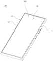
图1是本申请实施方式的电子装置的结构示意图;FIG. 1 is a schematic structural diagram of an electronic device according to an embodiment of the present application;
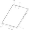
图2是本申请实施方式的电子装置的另一结构示意图;FIG. 2 is another schematic structural view of an electronic device according to an embodiment of the present application;
图3是本申请实施方式的电子装置的立体分解示意图;FIG. 3 is a three-dimensional exploded schematic diagram of an electronic device according to an embodiment of the present application;
图4是本申请实施方式的电子装置的平面示意图;4 is a schematic plan view of an electronic device according to an embodiment of the present application;
图5是图4中的电子装置沿线V-V的剖面示意图;5 is a schematic cross-sectional view of the electronic device in FIG. 4 along the line V-V;
图6是本申请实施方式的电子装置的另一平面示意图;6 is another schematic plan view of an electronic device according to an embodiment of the present application;
图7是图6中的电子装置沿线VII-VII的剖面示意图;7 is a schematic cross-sectional view of the electronic device in FIG. 6 along line VII-VII;
图8是本申请实施方式的电子装置的部分结构示意图;FIG. 8 is a partial structural schematic diagram of an electronic device according to an embodiment of the present application;
图9是本申请实施方式的电子装置的壳体的第二部分的结构示意图;9 is a schematic structural view of a second part of the casing of the electronic device according to the embodiment of the present application;
图10是本申请实施方式的电子装置的壳体的第二部分的另一结构示意图;FIG. 10 is another structural schematic diagram of the second part of the casing of the electronic device according to the embodiment of the present application;
图11是本申请实施方式的电子装置的又一结构示意图;FIG. 11 is another schematic structural diagram of an electronic device according to an embodiment of the present application;
图12是本申请实施方式的电子装置的再一结构示意图;FIG. 12 is another schematic structural view of the electronic device according to the embodiment of the present application;
图13是本申请实施方式的电子装置的再一结构示意图;FIG. 13 is another schematic structural view of the electronic device according to the embodiment of the present application;
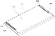
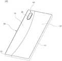
图14是本申请实施方式的电子装置的再一结构示意图;FIG. 14 is another schematic structural view of the electronic device according to the embodiment of the present application;
图15是本申请实施方式的电子装置的剖面示意图;和15 is a schematic cross-sectional view of an electronic device according to an embodiment of the present application; and
图16是本申请实施方式的电子装置的另一剖面示意图。FIG. 16 is another schematic cross-sectional view of the electronic device according to the embodiment of the present application.
具体实施方式detailed description
以下结合附图对本申请的实施方式作进一步说明。附图中相同或类似的标号自始至终表示相同或类似的元件或具有相同或类似功能的元件。Embodiments of the present application will be further described below in conjunction with the accompanying drawings. The same or similar reference numerals in the drawings represent the same or similar elements or elements having the same or similar functions throughout.
另外,下面结合附图描述的本申请的实施方式是示例性的,仅用于解释本申请的实施方式,而不能理解为对本申请的限制。In addition, the embodiments of the present application described below in conjunction with the accompanying drawings are exemplary, and are only used to explain the embodiments of the present application, and should not be construed as limiting the present application.
下文的公开提供了许多不同的实施方式或例子用来实现本申请的不同结构。为了简化本申请的公开,下文中对特定例子的部件和设置进行描述。当然,它们仅仅为示例,并且目的不在于限制本申请。此外,本申请可以在不同例子中重复参考数字和/或参考字母,这种重复是为了简化和清楚的目的,其本身不指示所讨论各种实施方式和/或设置之间的关系。The following disclosure provides many different implementations or examples for implementing different structures of the present application. To simplify the disclosure of the present application, components and arrangements of specific examples are described below. Of course, they are examples only and are not intended to limit the application. Furthermore, the present application may repeat reference numerals and/or reference letters in various instances, such repetition is for simplicity and clarity and does not in itself indicate a relationship between the various embodiments and/or arrangements discussed.
请结合图1至图3,本实施方式的电子装置100包括壳体10、卷轴20、柔性显示屏组件30、限位件40、盖体50、摄像头60、主板101和驱动机构70。卷轴20、柔性显示屏组件30、限位件40、盖体50、摄像头60和主板以及驱动机构70均可设置在壳体10。可以理解的是,本申请实施方式的电子装置100包括但不限于手机、平板等移动终端或者其它便携式电子设备,在本文中,以电子装置100为手机为例进行说明。Please refer to FIG. 1 to FIG. 3 , the
请结合图4至图7,在本实施方式中,壳体10包括第一部分12和第二部分14,第一部分12和第二部分14能够相对运动。具体地,在本实施方式中,第一部分12和第二部分14滑动连接,也即是说,第二部分14能够相对第一部分12滑动。Please refer to FIG. 4 to FIG. 7 , in this embodiment, the
请参阅图3至图7,在一实施例中,第一部分12可以基本呈矩形体状,第一部分12形成有容置空间120。容置空间120可用于放置卷轴20、限位件40、摄像头60、主板101和驱动机构70等部件。当然,请结合图4和图6,容置空间120也还可以用于堆叠放置电子装置100的其它电气元件,例如电池102、副板103,副板103可用于设置电子装置100的扬声器和麦克风等电气件。Referring to FIGS. 3 to 7 , in an embodiment, the
为了实现轻薄化,电子装置100内部用于堆叠电气元件的空间非常有限,本实施例在第一部分12内设置卷轴20可收纳柔性显示屏组件30,占用空间小,可以为其它电气元件的堆叠设计提供较大的空间。In order to achieve lightness and thinness, the space for stacking electrical components inside the
请结合图3和图8,第一部分12包括第一顶板122,第一顶板122开设有第一开口1222和第二开口1224,第一开口1222和第二开口1224均连通容置空间120。第一开口1222的开设方向与第二开口1224的方向垂直。第一开口1222用于供柔性显示屏组件30的一端穿设以使柔性显示屏组件30的一端与卷轴20连接,第二开口1224用于供驱动机构70从容置空间120露出以与第二部分12连接。Please refer to FIG. 3 and FIG. 8 , the
具体地,请参阅图3和图8,在本实施方式中,第一开口1222可沿电子装置100纵向方向开设,第二开口1224可沿电子装置100的横向方向开设。第二开口1224的数量可以为两个,两个第二开口1224位于第一顶板122的两侧且沿纵向方向对称设置。Specifically, referring to FIG. 3 and FIG. 8 , in this embodiment, the
第二部分14可相对第一部分12沿电子装置100的横向方向运动。此外,第一部分12开设有滑槽124,滑槽124用于与第二部分14配合以使得第二部分14能够相对第一部分12滑动。The
需要指出的是,在本申请的描述中,需要理解的是,术语“中心”、“纵向”、“横向”、“长度”、“宽度”、“厚度”、“上”、“下”、“竖直”、“水平”、“顶”、“底”、“内”、“外”指示的方位或位置关系为基于附图所示的方位或位置关系,仅是为了便于描述本申请和简化描述,而不是指示或暗示所指的装置或元件必须具有特定的方位、以特定的方位构造和操作,因此不能理解为对本申请的限制。此外,术语“第一”、“第二”仅用于描述目的,而不能理解为指示或暗示相对重要性或者隐含指明所指示的技术特征的数量。由此,限定有“第一”、“第二”的特征可以明示或者隐含地包括一个或者更多个所述特征。在本申请的描述中,“多个”的含义是两个或两个以上,除非另有明确具体的限定。It should be noted that in the description of the present application, it should be understood that the terms "center", "longitudinal", "transverse", "length", "width", "thickness", "upper", "lower", The orientation or positional relationship indicated by "vertical", "horizontal", "top", "bottom", "inner" and "outer" is based on the orientation or positional relationship shown in the drawings, and is only for the convenience of describing the present application and The description is simplified, rather than indicating or implying that the device or element referred to must have a specific orientation, be constructed in a specific orientation, and operate, and thus should not be construed as limiting the application. In addition, the terms "first" and "second" are used for descriptive purposes only, and cannot be interpreted as indicating or implying relative importance or implicitly specifying the quantity of indicated technical features. Thus, a feature defined as "first" or "second" may explicitly or implicitly include one or more of said features. In the description of the present application, "plurality" means two or more, unless otherwise specifically defined.
请参阅图3、图5和图7,第二部分14位于第一部分12上,第二部分14也可以基本成矩形体状,第二部分14包括滑动部144和第二顶板142。滑动部144连接在第二顶板142纵向的两侧且基本对称设置。滑动部144用于与第一部分12的滑槽124配合以实现第一部分12和第二部分14的滑动连接,第二顶板142和第一顶板122贴合。需要说明的是,本文中,“贴合”可以理解为两者接触但不影响两者之间的滑动,或者可以理解为两者之间的间隙在装配误差范围之内。Referring to FIG. 3 , FIG. 5 and FIG. 7 , the
需要指出的是,在本申请中,除非另有明确的规定和限定,第一特征在第二特征之“上”或之“下”可以包括第一和第二特征直接接触,也可以包括第一和第二特征不是直接接触而是通过它们之间的另外的特征接触。而且,第一特征在第二特征“之上”、“上方”和“上面”包括第一特征在第二特征正上方和斜上方,或仅仅表示第一特征水平高度高于第二特征。第一特征在第二特征“之下”、“下方”和“下面”包括第一特征在第二特征正下方和斜下方,或仅仅表示第一特征水平高度小于第二特征。It should be pointed out that in this application, unless otherwise clearly specified and limited, the first feature being "on" or "below" the second feature may include direct contact between the first and second features, and may also include the first feature being in direct contact with the second feature. The first and second features are not in direct contact but are in contact through another feature between them. Moreover, "above", "above" and "above" the first feature on the second feature include that the first feature is directly above and obliquely above the second feature, or simply means that the first feature is horizontally higher than the second feature. "Below", "beneath" and "under" the first feature to the second feature include that the first feature is directly below and obliquely below the second feature, or simply means that the first feature has a lower level than the second feature.
可以理解的是,在本实施方式中,第二部分14可相对第一部分12滑动以远离或者靠近第一部分12。在本实施方式中,“第一部分12和第二部分14做相离运动”可以理解为第二部分14相对第一部分12滑动且滑动方向背离第一部分12。另外,在本实施方式中,第一部分12和第二部分14也可做相向运动,两者做相向运动可以理解为第二部分14相对第一部分12滑动且滑动方向朝向第一部分12。It can be understood that, in this embodiment, the
还需要指出的是,在本申请的描述中,需要说明的是,除非另有明确的规定和限定,术语“安装”、“相连”、“连接”应做广义理解,例如,可以是固定连接,也可以是可拆卸连接,或一体地连接;可以是机械连接;可以是直接相连,也可以通过中间媒介间接相连,可以是两个元件内部的连通或两个元件的相互作用关系。对于本领域的普通技术人员而言,可以根据具体情况理解上述术语在本申请中的具体含义。It should also be pointed out that in the description of this application, it should be explained that unless otherwise clearly specified and limited, the terms "installation", "connection" and "connection" should be understood in a broad sense, for example, it may be a fixed connection , can also be a detachable connection, or an integral connection; it can be a mechanical connection; it can be a direct connection or an indirect connection through an intermediary, and it can be an internal communication between two components or an interaction relationship between two components. Those of ordinary skill in the art can understand the specific meanings of the above terms in this application according to specific situations.
请参阅图1、图4和图5,在本实施方式中,在第一部分12和第二部分14做相向运动至极限位置(即第一部分12和第二部分14相互靠近至第一部分12和第二部分14配合在一起时)时,第一部分12和第二部分14两者整体组成一个基本呈矩形体状的壳体10。请参阅图2、图6和图7,在第一部分12和第二部分14做相离运动(即两者相互远离)时,第二部分14远离第一部分12。Referring to Fig. 1, Fig. 4 and Fig. 5, in the present embodiment, the
请参阅图3、图5和图7,卷轴20转动设置在第一部分12,具体地,卷轴20转动设置在容置空间120内。也即是说,卷轴20安装在第一部分12且可相对第一部分12转动。卷轴20用于与驱动机构70连接以使卷轴20能够在驱动机构70的驱动下相对于第一部分12转动以释放或者卷收柔性显示屏组件30。Referring to FIG. 3 , FIG. 5 and FIG. 7 , the
可以理解的是,卷轴20转动设置在第一部分12可以指卷轴20直接地安装在第一部分12,也可以指卷轴20通过其它介质安装在第一部分12。It can be understood that the rotatable arrangement of the
此外,请继续参阅图5和图7,柔性显示屏组件30的一端连接在第二部分14,在本实施例中,该端部固定连接第二部分14,在其它实施例中,该端部也可以通过一活动机构连接第二部分14,例如上述活动机构可以是用于调节柔性显示屏组件30紧绷度的结构。柔性显示屏组件30的另一端设在卷轴20上,使得部分柔性显示屏组件30可以卷绕在卷轴20上。卷轴20可用于卷收柔性显示屏组件30和释放柔性显示屏组件30。其中,在第一部分12和第二部分14做相离运动时,卷轴20能够转动以释放柔性显示屏组件30,从而扩展柔性显示屏组件30的显示部分301。具体地,柔性显示屏组件30的一端与第二部分14固定连接,另一端穿过第一部分12的第一开口1222后与设置在容置空间120内的卷轴20连接。In addition, please continue to refer to FIG. 5 and FIG. 7, one end of the
如此,在第一部分12和第二部分14做相离运动时,卷轴20能够转动以释放柔性显示屏组件30,从而扩展柔性显示屏组件30的显示部分301。如此,可对电子装置100的屏幕显示区域的大小进行自由调节,在不需要使用大屏幕时,可以不对显示部分301进行扩展,从而使得整机尺寸较小,方便携带;在需要使用大屏幕时可以扩展柔性显示屏组件30的显示部分301以提高用户的操作体验。In this way, when the
可以理解,请参阅图5,在一种情况下,第一部分12和第二部分14靠近连接在一起,在这样的情况下,柔性显示屏组件30的显示部分301没有被扩展,原显示部分301中没有被扩展的部分,被收容于容置空间120内,电子装置100处于窄屏模式,此时,柔性显示屏组件30的一部分卷设在卷轴20上,一部分位于第一顶板122上方且从壳体10露出以用于显示。需要说明的是,在本实施方式中“柔性显示屏组件30的显示部分301”可以理解为位于第二部分14的第二顶板142上方的部分,即,从壳体10上露出的部分。It can be understood that referring to FIG. 5, in one case, the
请参阅图7,在需要扩展柔性显示屏组件30的显示部分301时,第一部分12和第二部分14做相离运动,这样,第二部分14会带动柔性显示屏组件30的伸展,此时,卷轴20可释放柔性显示屏组件30,从而使得柔性显示屏组件30的显示部分301增大,进而提高用户的操作体验以及需求。在这样的情况下,电子装置100处于扩展模式。Referring to Fig. 7, when the
可以理解的是,第二部分14和第一部分12两者做相离运动时存在极限位置,在处于极限位置时,电子装置100的显示区域最大,即柔性显示屏32组从壳体10露出的区域最大,也即柔性显示屏组件30的显示部分301面积最大(如图7所示)。在第一部分12和第二部分14靠近且连接配合在一起时,电子装置100的显示区域最小,即柔性显示屏组件30的显示部分301最小,也即柔性显示屏组件30的显示部分301面积最小(如图5所示)。It can be understood that there is a limit position when the
在本实施方式中,柔性显示屏组件30的一端固定连接在第二部分14,可以指的是柔性显示组件30的一端直接固定在第二部分14,也可以指柔性显示组件30通过其它介质固定在第二部分14。柔性显示屏组件30的一端与相对于第二部分14无法运动。In this embodiment, one end of the
本申请的实施方式中,柔性显示屏组件30的一端指的是柔性显示屏组件30的第一边缘,柔性显示屏组件30的另一端指的是柔性显示组件30的第二边缘,第二边缘与第一边缘相对设置。In the embodiment of the present application, one end of the
具体地,请参阅图3、图5和图7,柔性显示屏组件30包括柔性显示屏32和柔性支撑件34,柔性显示屏32与柔性支撑件34层叠设置且固定连接。Specifically, referring to FIG. 3 , FIG. 5 and FIG. 7 , the flexible
请参阅图5,柔性显示屏32包括第一区域322和与第一区域322连接的第二区域324。第一区域322贴设在第二顶板142上,第一区域322与第二顶板142相对应,第一区域322可通过光学胶(Optically Clear Adhesive,OCA)与第二顶板142固定连接。第二区域324至少部分地位于第一部分12的容置空间120内且贴设在柔性支撑件34上。Referring to FIG. 5 , the
柔性支撑件34设置在第二区域324的底部并且完全覆盖第二区域324,柔性支撑件34也可以通过光学胶(Optically Clear Adhesive,OCA)与第二区域324固定连接。在图5和图7所示的示例中,柔性支撑件34完全覆盖且超出第二区域324,柔性支撑件34的超出部分与卷轴20连接,即超出部分卷设在卷轴20上。请参阅图5,在电子装置100处于窄屏模式时,柔性支撑件34卷设在卷轴20上,柔性显示屏32大致呈“U”字型。这样,柔性支撑金34的支撑面积较大,从而可减小柔性显示屏32出现按压变形等现象。The
如此,在电子装置100处于窄屏模式时(即第一部分12和第二部分14做相向运动至极限位置时),卷轴20卷收的仅仅只是柔性支撑件34,而柔性显示屏32不会直接被卷轴20卷收,这样可以减少柔性显示屏32的被弯折程度和次数,提高了柔性显示屏32的使用寿命。当然,可以理解,在其它实施方式中,柔性显示屏32也可以是与柔性支撑件34完全对应后两者均与卷轴20连接,卷轴20可将柔性支撑件34和柔性显示屏32两者同时卷收和同时释放,具体设置方式在此不作限制。另外,柔性支撑件34完全覆盖第二区域324,柔性支撑,件34的支撑面积较大,这样可减小柔性显示屏32出现按压变形等现象。In this way, when the
此外,在本实施方式中,柔性显示屏32大致呈的“U”字型,电子装置100的主板101、电池102、副板103和传感器等电气元件可以收纳在柔性显示屏组件30围成的空间内。这样,柔性显示屏组件30的设置方式不会影响主板101和电池102等电气元件的摆放,有效的提高了空间的利用率,有利于主板101、电池102等电气元件的堆叠和摆放。In addition, in this embodiment, the
请参阅图5和图7,在本实施方式中,在第一部分12和第二部分14做相离运动时,柔性支撑件34抵持第一部分12以使柔性显示屏32的显示部分301保持平整。Please refer to FIG. 5 and FIG. 7. In this embodiment, when the
具体地,在第一部分12和第二部分14相离时,柔性支撑件34与第一顶板122相对设置且与第一顶板122贴合。柔性支撑件34位于柔性显示屏32与第一顶板122之间且填充柔性显示屏32与第一顶板122之间的间隙。也即是说,柔性支撑件34的厚度等于第一部分12的上表面与第二部分14的上表面之间的距离。Specifically, when the
可以理解,请参阅图7,在第一部分12与第二部分14做相离运动时,第一顶板122的上表面和第二顶板142的上表面之间具有高度差,柔性显示屏32固定连接在第二顶板142的上表面,此时,柔性支撑件34抵持第一部分12的第一顶板122,即并柔性支撑件34填充柔性显示屏32与第一顶板122之间的间隙。也即是说,由于第一顶板122和第二顶板142上下贴合,柔性显示屏32固定连接在第二顶板142的上表面。因此,柔性支撑件34的厚度等于第二顶板142的厚度可以填充第一顶板122和第二顶板142之间的高度差,即填充柔性显示屏32与第一顶板122之间的间隙,从而使得柔性显示屏32在运动时能够保持平整,从而避免在电子装置100处于扩展模式时柔性显示屏32在被触摸和按压时时出现塌陷现象,提高用户的操作体验。It can be understood that, referring to FIG. 7 , when the
此外,请继续参阅图3、图5和图7,柔性支撑件34的底部形成有第一齿部342,第一齿部342用于与限位件40啮合以使得在限位件40能够支撑柔性显示屏组件30并保持柔性显示屏组件30能够平稳运动。In addition, please continue to refer to FIG. 3 , FIG. 5 and FIG. 7 , the bottom of the
另外,在本实施方式中,柔性支撑件34可由磁性材料制成,第一顶板122可由能够被磁化的金属材料制成或者第一顶板122包括涂覆在其表面的能够被磁化的金属层。这样,在第二部分14相对于第一部分12做相离运动以扩展柔性显示屏组件30的显示部分301时,柔性支撑件34可以吸附在第一顶板122上。这样可以防止在操作时柔性显示屏组件30出现错位或者窜动现象。In addition, in this embodiment, the flexible supporting
请参阅图5、图7和图8,限位件40转动设置在第一部分12的容置空间120内且从第一开口1222露出,柔性显示屏组件30的中间部分绕设在限位件40上,限位件40用于限制柔性显示屏组件30的形态。Referring to FIG. 5 , FIG. 7 and FIG. 8 , the limiting
具体地,限位件40呈柱状,限位件40的圆周上形成有第二齿部42,第二齿部42用于与柔性支撑件34上的第一齿部342啮合以对柔性显示屏组件30进行支撑和对柔性显示屏组件30的扩展进行导向。可以理解,柔性显示屏组件30的中间部分可以理解为位于柔性显示屏组件30的两端之间的部位。Specifically, the limiting
如此,限位件40可以限制柔性显示组件30的形态,以使柔性显示组件30的显示部分301可以呈平整的状态,即可以使得柔性显示屏组件30保持处于U型状态。另外,限位件40与柔性支撑件34啮合既可以对柔性显示屏组件30进行支撑,又可以在第二部分14带动柔性显示屏组件30运动时进行导向以保持柔性显示屏组件30能够的平稳运动。In this way, the limiting
具体地,在本实施方式中,限位件40为一个导向齿轮,限位件40设置在于第一开口1222对应的位置,柔性显示屏组件30的中间部分绕设在限位件40上,柔性支撑件34上的第一齿部342和第二齿部42啮合。也即是说,柔性显示屏组件30的一端与第二部分14固定连接,另一端穿过第一开口1222并绕过限位件40后与卷轴20连接。在第二部分14带动柔性显示屏32的一端运动时,限位件40在柔性支撑件34的带动下逐渐转动,卷轴20逐渐释放柔性支撑件34的一端。Specifically, in this embodiment, the limiting
可以理解的是,在其它实施方式中,限位件40也可以不形成有第二齿部42,而是直接为光轴或者滚筒,柔性支撑件34也可不形成第一齿部342,限位件40和柔性支撑件34直接滚动连接,柔性显示屏组件30直接绕过光轴或者滚筒,这样,限位件40同样也能够对柔性显示屏32进行支撑和导向。It can be understood that, in other embodiments, the limiting
请参阅图5、图7和图10,在本实施方式中,摄像头60可设置在第一部分12的容置空间120,盖体50与第一部分12连接并盖设容置空间120,摄像头60能够通过盖体50进行图像采集。也即是说,在本实施方式中,第一部分12与盖体50是形成一个整体,在第二部分14相对于第一部分12运动时,摄像头60不会跟随移动,在处于扩展模式时,摄像头60位于整个柔性显示屏32的中间位置。Referring to Fig. 5, Fig. 7 and Fig. 10, in this embodiment, the
在本实施方式中,盖体50与第一部分12可拆卸地连接,如此,可以方便将盖体50拆卸下来对堆叠设置在容置空间120内的主板101、电池102或者传感器等电气元件进行维修和更换。可以理解,在其它实施方式中,盖体50与第一部分12也可为一体结构,两者一体成型,具体设置方式在此不作限制。In this embodiment, the
此外,请结合图11和图12,盖体50上可开设有与摄像头60位置相对应的透光部56,光线可透过透光部56以被摄像头60接收以使摄像头60能够通过盖体50进行图像采集以对外进行拍摄。这样,透光部56可以在不影响摄像头60的拍摄效果的前提下对摄像头60进行保护,从而防止摄像头60直接暴露在壳体10外而导致意外划伤摄像头60。在这样的情况下,摄像头60可以是手机的后置摄像头,后置摄像头可以通过盖体50上的透光部56进行图像采集。可以理解的是,在一些实施方式中,摄像头60也可以是手机的前置摄像头,在这样的情况下,摄像头60可以是通过在柔性显示屏组件30上开孔或者是在壳体10上开孔以进行图像采集,也可以是采用弹出或者滑出式机构,在需要使用前置摄像头时,可以通过弹出机构或者滑出机构将摄像头60从壳体10内弹出或者滑出,这样可以提高电子装置100的屏占比。In addition, please refer to FIG. 11 and FIG. 12 , the
可以理解的是,请参阅图13和图14,在其它实施方式中,摄像头60也可以是与第二部分14固定连接并通过第二部分14采集图像。具体地,在这样的实施方式中,第二部分14形成有收纳空间140,摄像头60设置在收纳空间140内,光线能够透过第二部分14以被摄像头60接收从而使得摄像头60能够通过第二部分60进行图像采集,在第二部分14相对第一部分12运动时,摄像头60也会跟随第二部分14运动。这样,可以在实现能够调节柔性显示屏组件30的显示区域301的大小的也不会影响摄像头60的拍照和摄像功能,从而用户在任何情况下都可以方便拍照使用。It can be understood that, referring to FIG. 13 and FIG. 14 , in other implementation manners, the
请参阅图15,在这样的实施方式中,第二部分14还包括底板146,底板146和第二顶板142相对设置且限定形成收纳腔室140,也即是说,摄像头60可设置在第二顶板142和底板146之间的收纳腔室140内,即摄像头30可通过第二部分14的底板146进行图像采集。当然,可以理解的是,摄像头60也可以只是部分位于收纳腔室140内,只要能够实现摄像头60的正常拍摄和拍照功能即可,具体在此不作限制。Please refer to FIG. 15 , in such an embodiment, the
进一步地,在这样的实施方式中,为了使得摄像头60能够正常拍照和拍摄,底板146上可开设有与摄像头60相对应的通孔或者底板146包括与摄像头60相对应的透光区域,摄像头60从通孔露出或者是通过透光区域采集图像,即光线可穿过通孔或者透过透光区域以被摄像头60接收,透光区域可采用玻璃等透光材料制成。Further, in such an embodiment, in order to enable the
此外,请参阅图15和图16,在这样的实施方式中,盖体50包括第一连接部52和第二连接部54,第一连接部52固定连接在第一部分12的底部并封闭容置空间120,第二连接部54固定连接在第二部分14的底部,摄像头60能够通过第二连接部54采集图像。也即是说,第二连接部54与第一部分12固定连接,第二连接部54与第二部分14固定连接,第二连接部54可相对于第一连接部52分运动,摄像头60能够跟随第二部分14运动。In addition, please refer to FIG. 15 and FIG. 16 , in such an embodiment, the
具体地,第二连接部52可固定或者可拆卸地连接在底板146的底板,第二连接部52包括与通孔或者透光区域对应的透光部56,也即是说,摄像头60、通孔(或者透光区域)以及透光部56三者是相对应的。这样,摄像头60可以通过通孔(或者透光区域)以及透光部56接收光线以进行图像采集。Specifically, the second connecting
请参阅图13和图15,在电子装置100处于窄屏模式,即第一部分12和第二部分14相向运动至极限位置时,第一连接部52和第二连接部54拼接以共同形成电子装置100的盖体50。请参阅图14和图16,在第二部分14相对第一部分12做相离运动时,第二连接部54与第二连接部52分离。Please refer to FIG. 13 and FIG. 15 , when the
具体地,请结合图13和图14,在这样的实施方式中,第一连接部52上形成有呈弧形的凹部542,第二连接部54上形成有与凹部542相匹配的凸部522,凸部522也呈弧形在电子装置100处于窄屏模式时(如图13和图15所示),凹部542与凸部522拼接在一起以实现第一连接部52和第二连接部54的拼接。可以理解的是,第一连接部52和第二连接部54也可以制作成其它形态,例如,两者都呈矩形状,两者可直接拼接成盖体50,再例如,两者的其中一个上可形成有规则排列的凸起,在另一个上形成有与凸起对应的凹槽,这样,在电子装置100处于扩展模式时可以丰富壳体10的形态以提高美感。Specifically, please refer to FIG. 13 and FIG. 14 , in such an embodiment, an arc-shaped
进一步地,在这样的实施方式中,第一连接部52和第二连接部54可设计成两种不同的颜色效果,这样可以丰富电子装置100的外观效果。Further, in such an embodiment, the
请参阅图3、图5和图7,在本实施方式中,驱动机构70可设置在第一部分12的容置空间120内,驱动机构70包括第一驱动机构72和第二驱动机构74。第一驱动机构72与第二部分14连接,第一驱动机构72用于驱动第二部分14相对于第一部分12做相离运动以使卷轴20转动而释放柔性显示屏组件30,从而扩展柔性显示屏组件30的显示部分301。第二驱动机构74与卷轴20连接,第二驱动机构74用于驱动卷轴20转动以卷收柔性显示屏组件30从而缩减柔性显示屏组件30的显示部分301。Referring to FIG. 3 , FIG. 5 and FIG. 7 , in this embodiment, the
具体地,第一驱动机构72可包括第一电机(图未示出)和第一传动结构722,第一电机可固定设置在第一部分12的容置空间120内。第一传动结构722和第二部分12连接,第一电机用于通过第一传动结构722驱动第二部分12相对于第一部分12运动。Specifically, the
进一步地,第一传动结构722包括第一传动齿轮723和齿条724。第一传动齿轮723固定在第一电机的电机轴上,齿条724与第二部分14固定连接,齿条724与第一传动齿轮723啮合。具体地,在本实施方式中,齿条724与第二部分14的第二顶板142一体成型,也即是说,齿条724可以直接一体成型在第二顶板142的下表面。可以理解的是,在其它实施方式中,齿条724也可以是与第二部分14分体成型,然后两者通过焊接等方式固定连接在一起,具体在此不作限制。这样,通过齿轮齿条啮合方式可使得传动稳定可靠,同时组装也较为简便。可以理解的是,在其它实施方式中,第一传动结构722也可采用更多的齿轮组成传动齿轮组后与齿条724啮合来进行传动,具体在此不作限制。Further, the
请再次参阅图5和图7,第二驱动机构74包括第二电机(图未示出)和第二传动结构742。第二电机也可固定设置在第二部分12的容置空间120内。第二传动结构742和第二电机以及卷轴20连接,第二电机用于通过第二传动结构742驱动卷轴20转动以卷收柔性显示屏组件30从而缩减柔性显示屏组件30的显示部分301。Please refer to FIG. 5 and FIG. 7 again, the
进一步地,第二传动结构742包括第二传动齿轮743和第三传动齿轮744,第二传动齿轮743固定在卷轴20上且与卷轴20同心设置,第三传动齿轮744固定设置在第二电机的电机轴上且与第二传动齿轮743啮合。第二电机的启动时带动第三传动齿轮744转动,第三传动齿轮744带动第二传动齿轮742转动,从而带动卷轴20转动。这样,通过齿轮啮合的方式进行传动可使得传动稳定可靠,同时组装也较为简便。可以理解的是,在其它实施方式中,第一传动结构722也可采用更多的齿轮组成传动齿轮组后与齿条724啮合来进行传动,具体在此不作限制。Further, the
可以理解的是,在其它实施方式中,卷轴20也可以是与第二电机的电机轴直接连接或者也可至通过单个传动齿轮或者更多传动齿轮与第二电机的电机轴连接,具体在此不作限制。It can be understood that, in other embodiments, the
在本实施方式中,在需要对扩展电子装置100的显示区域,即扩展柔性显示屏组件30的显示部分301时,可通过第一电机带动第一传动齿轮723转动,第一传动齿轮723通过齿条724驱动第二部分14相对于第一部分12做相离运动,第二部分14带动柔性显示屏组件30的伸展,即带动柔性显示屏组件30的一端相对于第一部分12做相离运动,柔性显示屏组件30带动卷轴20转动而释放柔性显示屏组件30,进而达到扩展柔性显示屏组件30的显示部分301的目的。需要指出的是,在本实施方式中,在扩展显示部分301的过程中,第二电机处于关闭状态,卷轴20处于自由状态,即,卷轴20能够在柔性显示屏组件30的带动下自由转动。当然,在一些实施方式中,第二电机也可处于开启状态,在第一电机驱动第二部分14相对第一部分12做相离运动时,第二电机转动以同步驱动卷轴20转动以释放柔性显示屏组件。In this embodiment, when it is necessary to expand the display area of the
在需要缩减柔性显示屏组件30的显示部分301时,可通过第二电机带动第三传动齿轮744转动,从而带动第二传动齿轮743转动从而带动卷轴20转动以卷收柔性显示屏组件30,柔性显示屏组件30可带动第二部分14相对于第一部分12做相向运动,进而达到缩减柔性显示屏组件30的显示部分301的目的。需要指出的是,在缩减显示部分301的过程中,第一电机处于关闭状态,第一传动齿轮723处于自由状态,即第一传动齿轮723能够在第二部分14相对于第一部分12做相离运动时在第二部分14的带动下转动。当然,在一些实施方式中,第以电机也可处于开启状态,第二电机转动以驱动卷轴20转动以卷收柔性显示屏组件。在第一电机同步驱动第二部分14相对第一部分12做相向运动。When the
可以理解的是,在本实施方式中,在单位时间内,第二部分14的运动行程与卷轴20转动所释放或者卷收的柔性显示屏组件30的长度是相等的。也即是说,在第二部分14相对于第一部分12做相离运动时运动多少距离,卷轴20就转动以释放多少长度,在第二部分14相对于第一部分12做相向运动时运动多少距离,卷轴20就转动以卷收多少长度,这样可以保证柔性显示屏组件30能够平稳的运动。It can be understood that, in this embodiment, within a unit time, the movement stroke of the
此外,还可以理解的是,在某些实施方式中,为了保证卷轴20卷收和释放柔性显示屏组件30的平稳性,第一驱动机构72和第二驱动机构74的数量均可为两个,卷轴20的数量也为两个,两个第一驱动机构72可沿电子装置100的纵向方向对称设置在容置空间120内且分别与第二部分14连接,两个第二驱动机构74也可可沿电子装置100的纵向方向对称设置在容置空间120内且也分别与两个卷轴20连接。这样,可通过两个相同的第一驱动机构72同步驱动第二部分14的平稳移动以及通过两个相同的第二驱动机构74来实现两个卷轴20的同步且平稳转动,从而保证电子装置100在扩展柔性显示屏组件30的显示部分301时的运动的可靠性。In addition, it can also be understood that, in some embodiments, in order to ensure the stability of the
下面,对本实施方式的电子装置100工作原理进行介绍。Next, the working principle of the
请参阅图4至图7,正如上述,电子装置100能够在窄屏模式和扩展模式之间切换。在图4和图5所示的状态中,电子装置100处于窄屏模式,在图6和图7所示的状态中,电子装置100处于扩展模式。在处于窄屏模式时,第一部分12和第二部分14相互配合以形成壳体10,柔性显示屏组件30的一端卷设在卷轴20上,另一端固定连接第二部分14,此时,柔性显示屏组件30只有较小的部分从壳体10露出,显示部分301较窄,这样可方便用户携带。Please refer to FIG. 4 to FIG. 7 , as mentioned above, the
在用户需要较大的显示部分301时,可通过第一驱动机构72驱动第二部分14相对于第一部分12做相离运动,此时,第二部分14带动柔性显示屏组件30伸展,柔性显示屏组件30带动卷轴20转动而释放柔性显示屏组件30,这样,柔性显示屏组件30的隐藏在壳体10内部分逐渐被第二部分14拉出(即从图4所示的状态运动至图6所示的状态),从而达到扩展柔性显示屏组件30的显示部分301的目的,此时,显示部分301的区域较大,可以方便用户操作以提高用户的操作体验。When the user needs a
在需要从扩展模式切换至窄屏模式时,第二驱动机构74驱动卷轴20转动从而逐渐卷收柔性显示屏组件30,柔性显示屏组件30带动第二部分14相对于第一部分12做相相运动,位于壳体10外的部分柔性显示屏组件30逐渐被拉回至第一部分12的容置空间120内,在运动至第一部分12和第二部分14之间的相向运动的极限位置时,第二驱动机构74停止运行,电子装置100回归至窄屏模式。When it is necessary to switch from the extended mode to the narrow screen mode, the
综合上述,本申请实施方式的电子装置100包括壳体10、卷轴20、柔性显示屏组件30、第一驱动机构72和第二驱动机构74。壳体10包括能够相对运动的第一部分12和第二部分14。卷轴20转动设置在第一部分12。柔性显示屏组件30的一端连接在第二部分14,另一端设在卷轴20上。第一驱动机构72连接第二部分14,第一驱动机构72用于驱动第二部分20相对于第一部分12做相离运动以使卷轴20转动而释放柔性显示屏组件30,从而扩展柔性显示屏组件30的显示部分301。第二驱动机构74与卷轴20连接,第二驱动机构74用于驱动卷轴20转动以卷收柔性显示屏组件30从而缩减柔性显示屏组件30的显示部分301。In summary, the
综上,在本申请实施方式的电子装置100中,第一驱动机构72可驱动第二部分14相对于第一部分12做相离运动以带动柔性显示屏组件30的一端运动从而带动卷轴20转动以释放柔性显示屏组件30的另一端以扩展柔性显示屏组件30的显示部分301。第二驱动机构74可驱动卷轴20转动以卷收柔性显示屏组件30的一端从而带动第二部分14相对于第一部分12做相向运动以缩减柔性显示屏组件30的显示部分301。如此,两个驱动机构的设置可以使得电子装置100在扩展或者缩减柔性显示屏组件30的显示部分301时保证柔性显示屏组件30的运动的平稳性和可靠性,也可使得柔性显示屏组件30在伸展和回收过程中不易出现褶皱。To sum up, in the
在本说明书的描述中,参考术语“某些实施方式”、“一个实施方式”、“一些实施方式”、“示意性实施方式”、“示例”、“具体示例”、或“一些示例”的描述意指结合所述实施方式或示例描述的具体特征、结构、材料或者特点包含于本申请的至少一个实施方式或示例中。在本说明书中,对上述术语的示意性表述不一定指的是相同的实施方式或示例。而且,描述的具体特征、结构、材料或者特点可以在任何的一个或多个实施方式或示例中以合适的方式结合。In the description of this specification, references to the terms "certain embodiments," "one embodiment," "some embodiments," "exemplary embodiments," "examples," "specific examples," or "some examples" To describe means that a specific feature, structure, material, or characteristic described in connection with the embodiment or example is included in at least one embodiment or example of the present application. In this specification, schematic representations of the above terms do not necessarily refer to the same embodiment or example. Furthermore, the described specific features, structures, materials or characteristics may be combined in any suitable manner in any one or more embodiments or examples.
尽管上面已经示出和描述了本申请的实施例,可以理解的是,上述实施例是示例性的,不能理解为对本申请的限制,本领域的普通技术人员在本申请的范围内可以对上述实施例进行变化、修改、替换和变型,本申请的范围由权利要求及其等同物限定。Although the embodiments of the present application have been shown and described above, it can be understood that the above embodiments are exemplary and should not be construed as limitations on the present application, and those skilled in the art can make the above-mentioned The embodiments are subject to changes, modifications, substitutions and variations, the scope of the present application is defined by the claims and their equivalents.
Claims (9)
Priority Applications (1)
| Application Number | Priority Date | Filing Date | Title |
|---|---|---|---|
| CN201911282283.2ACN112967597B (en) | 2019-12-13 | 2019-12-13 | Electronic device with a detachable cover |
Applications Claiming Priority (1)
| Application Number | Priority Date | Filing Date | Title |
|---|---|---|---|
| CN201911282283.2ACN112967597B (en) | 2019-12-13 | 2019-12-13 | Electronic device with a detachable cover |
Publications (2)
| Publication Number | Publication Date |
|---|---|
| CN112967597A CN112967597A (en) | 2021-06-15 |
| CN112967597Btrue CN112967597B (en) | 2022-12-30 |
Family
ID=76271053
Family Applications (1)
| Application Number | Title | Priority Date | Filing Date |
|---|---|---|---|
| CN201911282283.2AActiveCN112967597B (en) | 2019-12-13 | 2019-12-13 | Electronic device with a detachable cover |
Country Status (1)
| Country | Link |
|---|---|
| CN (1) | CN112967597B (en) |
Families Citing this family (4)
| Publication number | Priority date | Publication date | Assignee | Title |
|---|---|---|---|---|
| CN113709279B (en)* | 2021-08-31 | 2023-08-15 | Oppo广东移动通信有限公司 | Electronic device |
| CN115762332B (en)* | 2021-09-02 | 2025-09-05 | 北京小米移动软件有限公司 | electronic devices |
| CN114216012B (en)* | 2021-12-08 | 2023-07-04 | 合肥维信诺科技有限公司 | Flexible screen supporting device and display equipment |
| CN115035794B (en)* | 2022-06-10 | 2024-02-20 | 武汉华星光电半导体显示技术有限公司 | Flexible display modules and electronic devices |
Citations (3)
| Publication number | Priority date | Publication date | Assignee | Title |
|---|---|---|---|---|
| CN102419933A (en)* | 2010-09-28 | 2012-04-18 | 富泰华工业(深圳)有限公司 | Display and electronic device with same |
| CN105518767A (en)* | 2014-12-25 | 2016-04-20 | 深圳市柔宇科技有限公司 | Flexible display apparatus |
| CN106371506A (en)* | 2015-07-20 | 2017-02-01 | 三星电子株式会社 | Electronic device with flexible display |
Family Cites Families (5)
| Publication number | Priority date | Publication date | Assignee | Title |
|---|---|---|---|---|
| US7440265B2 (en)* | 2005-12-27 | 2008-10-21 | Lite-On Technology Corporation | Variable-sized screen |
| US9860998B2 (en)* | 2016-04-04 | 2018-01-02 | Mansoor Malik | Modular deployable display unit and system thereof |
| KR102389189B1 (en)* | 2017-11-29 | 2022-04-22 | 삼성전자주식회사 | Electronic device with flexible display having expandable display area |
| WO2019210766A1 (en)* | 2018-05-02 | 2019-11-07 | Guangdong Oppo Mobile Telecommunications Corp., Ltd. | Foldable screen assembly and electronic device |
| CN110491289B (en)* | 2019-07-29 | 2024-03-15 | 武汉华星光电半导体显示技术有限公司 | Display device |
- 2019
- 2019-12-13CNCN201911282283.2Apatent/CN112967597B/enactiveActive
Patent Citations (3)
| Publication number | Priority date | Publication date | Assignee | Title |
|---|---|---|---|---|
| CN102419933A (en)* | 2010-09-28 | 2012-04-18 | 富泰华工业(深圳)有限公司 | Display and electronic device with same |
| CN105518767A (en)* | 2014-12-25 | 2016-04-20 | 深圳市柔宇科技有限公司 | Flexible display apparatus |
| CN106371506A (en)* | 2015-07-20 | 2017-02-01 | 三星电子株式会社 | Electronic device with flexible display |
Also Published As
| Publication number | Publication date |
|---|---|
| CN112967597A (en) | 2021-06-15 |
Similar Documents
| Publication | Publication Date | Title |
|---|---|---|
| CN112991930B (en) | Electronic device with a detachable cover | |
| CN112991928B (en) | Electronic device with a detachable cover | |
| CN113067915B (en) | Mobile terminal | |
| CN112995364B (en) | Mobile terminal | |
| CN112967597B (en) | Electronic device with a detachable cover | |
| CN112991929B (en) | Electronic device | |
| CN112991927B (en) | Electronic device | |
| CN114844965B (en) | Electronic device | |
| CN112991933B (en) | Mobile terminal | |
| WO2021121157A1 (en) | Flexible display screen assembly and electronic device | |
| CN113068336A (en) | electronic device | |
| CN112968982B (en) | Electronic device | |
| WO2021115433A1 (en) | Electronic device | |
| CN112991932B (en) | electronic device | |
| CN112995371B (en) | mobile terminal | |
| CN113012568B (en) | electronic device |
Legal Events
| Date | Code | Title | Description |
|---|---|---|---|
| PB01 | Publication | ||
| PB01 | Publication | ||
| SE01 | Entry into force of request for substantive examination | ||
| SE01 | Entry into force of request for substantive examination | ||
| GR01 | Patent grant | ||
| GR01 | Patent grant |