CN112957590B - Ablation system, ablation device and bendable catheter - Google Patents
Ablation system, ablation device and bendable catheterDownload PDFInfo
- Publication number
- CN112957590B CN112957590BCN202011626219.4ACN202011626219ACN112957590BCN 112957590 BCN112957590 BCN 112957590BCN 202011626219 ACN202011626219 ACN 202011626219ACN 112957590 BCN112957590 BCN 112957590B
- Authority
- CN
- China
- Prior art keywords
- ring
- rack
- driven ring
- limiting
- distal end
- Prior art date
- Legal status (The legal status is an assumption and is not a legal conclusion. Google has not performed a legal analysis and makes no representation as to the accuracy of the status listed.)
- Active
Links
Images


Classifications
- A—HUMAN NECESSITIES
- A61—MEDICAL OR VETERINARY SCIENCE; HYGIENE
- A61M—DEVICES FOR INTRODUCING MEDIA INTO, OR ONTO, THE BODY; DEVICES FOR TRANSDUCING BODY MEDIA OR FOR TAKING MEDIA FROM THE BODY; DEVICES FOR PRODUCING OR ENDING SLEEP OR STUPOR
- A61M25/00—Catheters; Hollow probes
- A61M25/01—Introducing, guiding, advancing, emplacing or holding catheters
- A61M25/0105—Steering means as part of the catheter or advancing means; Markers for positioning
- A—HUMAN NECESSITIES
- A61—MEDICAL OR VETERINARY SCIENCE; HYGIENE
- A61B—DIAGNOSIS; SURGERY; IDENTIFICATION
- A61B18/00—Surgical instruments, devices or methods for transferring non-mechanical forms of energy to or from the body
- A—HUMAN NECESSITIES
- A61—MEDICAL OR VETERINARY SCIENCE; HYGIENE
- A61M—DEVICES FOR INTRODUCING MEDIA INTO, OR ONTO, THE BODY; DEVICES FOR TRANSDUCING BODY MEDIA OR FOR TAKING MEDIA FROM THE BODY; DEVICES FOR PRODUCING OR ENDING SLEEP OR STUPOR
- A61M25/00—Catheters; Hollow probes
- A61M25/0021—Catheters; Hollow probes characterised by the form of the tubing
- A—HUMAN NECESSITIES
- A61—MEDICAL OR VETERINARY SCIENCE; HYGIENE
- A61B—DIAGNOSIS; SURGERY; IDENTIFICATION
- A61B18/00—Surgical instruments, devices or methods for transferring non-mechanical forms of energy to or from the body
- A61B2018/00571—Surgical instruments, devices or methods for transferring non-mechanical forms of energy to or from the body for achieving a particular surgical effect
- A61B2018/00577—Ablation
- A61B2018/00583—Coblation, i.e. ablation using a cold plasma
- A—HUMAN NECESSITIES
- A61—MEDICAL OR VETERINARY SCIENCE; HYGIENE
- A61B—DIAGNOSIS; SURGERY; IDENTIFICATION
- A61B18/00—Surgical instruments, devices or methods for transferring non-mechanical forms of energy to or from the body
- A61B2018/00636—Sensing and controlling the application of energy
- A61B2018/00773—Sensed parameters
- A61B2018/00839—Bioelectrical parameters, e.g. ECG, EEG
Landscapes
- Health & Medical Sciences (AREA)
- Life Sciences & Earth Sciences (AREA)
- Veterinary Medicine (AREA)
- Public Health (AREA)
- Engineering & Computer Science (AREA)
- General Health & Medical Sciences (AREA)
- Biomedical Technology (AREA)
- Heart & Thoracic Surgery (AREA)
- Animal Behavior & Ethology (AREA)
- Hematology (AREA)
- Anesthesiology (AREA)
- Pulmonology (AREA)
- Biophysics (AREA)
- Surgery (AREA)
- Nuclear Medicine, Radiotherapy & Molecular Imaging (AREA)
- Otolaryngology (AREA)
- Medical Informatics (AREA)
- Molecular Biology (AREA)
- Media Introduction/Drainage Providing Device (AREA)
Abstract
Translated fromChinese
Description
Translated fromChinese技术领域technical field
本发明涉及医疗器械技术领域,特别涉及一种消融系统、消融装置及可调弯导管。The invention relates to the technical field of medical devices, in particular to an ablation system, an ablation device and an adjustable bendable catheter.
背景技术Background technique
介入诊疗是近几十年迅速推广的现代化医学技术,通常需要借助各种不同结构、形状、尺寸的导管装置,在患者体内病变部位与外界操作端之间建立通道,以导入各种各样的诊疗器械、药物、植入器械至病患的病变部位,或者导出病变部位的体液等。在医学领域,已有很多种介入型导管装置,如:导引导管、输送鞘管、引流导管等。Interventional diagnosis and treatment is a modern medical technology that has been rapidly promoted in recent decades. It usually requires the use of various catheter devices of different structures, shapes and sizes to establish channels between the diseased part of the patient's body and the external operating end, so as to introduce various types of catheters. Diagnosis and treatment devices, drugs, implanted devices into the diseased part of the patient, or to export body fluids from the diseased part, etc. In the medical field, there are many kinds of interventional catheter devices, such as guide catheters, delivery sheaths, drainage catheters, and the like.
介入型诊疗导管通常具有一个可供药物、体液、器械通过的内腔管。由于人体心血管循环系统迂回曲折的特性,介入型导管通常必须同时具备良好的柔顺性、扭控性、导向性以及足够的轴向与径向支撑力。另外,在介入型导管的设计制造过程中,会根据预期用途的不同,将导管远端制作成不同的弯曲形状,以适应特定病变部位的管腔解剖形态,使导管远端管口对准病变部位,将导管内的器械或药物精确导向病变部位。近年来,形态众多的远端预塑形介入型导管被陆续开发出来,并用于临床治疗。Interventional diagnostic catheters usually have an inner lumen through which drugs, body fluids, and instruments can pass. Due to the tortuous nature of the human cardiovascular circulatory system, interventional catheters usually must have good flexibility, twist control, guidance, and sufficient axial and radial support forces at the same time. In addition, during the design and manufacture of the interventional catheter, the distal end of the catheter will be made into different curved shapes according to the intended use to adapt to the lumen anatomy of the specific lesion site, so that the distal end of the catheter can be aligned with the lesion. The device or drug in the catheter is precisely directed to the lesion site. In recent years, a variety of distal pre-shaped interventional catheters have been developed and used in clinical treatment.
然而,在临床使用过程中,经常遇到人体管腔解剖结构的个体化差异,即使是根据特定的人体生理解剖结构而设计的远端预塑形鞘管,也难以适应个体化的人体管腔解剖结构,妨碍手术操作过程,进而影响手术效果。为了防备手术过程中出现此类问题,医生通常会预备几种不同规格的远端预塑形鞘管。一旦发现所选导管的远端形状不合适病变部位,就将该导管撤出管腔,选择其它规格的预塑形导管,重复操作插入管腔。有时,甚至要根据病患的生理解剖结构,在手术现场将鞘管远端重新塑形成所需的形状。如此,无疑增加了病患所承担的费用,增加了手术过程的复杂性,而且会延长患者暴露于X射线环境下的时间,不利于患者的健康。However, in the process of clinical use, individual differences in the anatomical structure of the human lumen are often encountered. Even the distal pre-shaped sheath designed according to the specific human physiological and anatomical structure is difficult to adapt to the individual human lumen. The anatomical structure hinders the surgical operation process, thereby affecting the surgical effect. To prevent such problems during surgery, doctors usually prepare several different sizes of distal pre-shaped sheaths. Once the shape of the distal end of the selected catheter is found to be inappropriate for the lesion site, the catheter is withdrawn from the lumen, pre-shaped catheters of other specifications are selected, and the operation is repeated to insert into the lumen. In some cases, the distal end of the sheath may even be reshaped at the surgical site to the desired shape based on the patient's anatomy. In this way, the cost borne by the patient will undoubtedly be increased, the complexity of the surgical procedure will be increased, and the time of exposure of the patient to the X-ray environment will be prolonged, which is not conducive to the patient's health.
发明内容SUMMARY OF THE INVENTION
为解决上述技术问题,本发明采用如下技术方案:一种可调弯导管,包括:In order to solve the above-mentioned technical problems, the present invention adopts the following technical solutions: an adjustable bendable catheter, comprising:
外鞘管,其远端具有柔性并且能够弯曲;an outer sheath, the distal end of which is flexible and capable of bending;
牵拉钢丝,位于所述外鞘管内,且所述牵拉钢丝的远端与所述外鞘管的远端固定连接,近端穿出所述外鞘管;A pulling wire is located in the outer sheath, and the distal end of the pulling wire is fixedly connected with the distal end of the outer sheath, and the proximal end passes through the outer sheath;
手柄,连接于所述外鞘管的近端;所述手柄包括调弯机构以及限位机构;所述调弯机构包括从动环以及旋钮,所述旋钮能够绕所述手柄的轴向旋转,所述从动环与所述牵拉钢丝的近端固定连接,且所述从动环能够随所述旋钮的转动而一起转动,进而使得所述牵拉钢丝的远端向近端移动,带动所述外鞘管的远端向一侧弯曲;所述限位机构用于限制所述从动环在一预设角度范围内的转动,而使所述外鞘管保持当前的弯曲状态。a handle, connected to the proximal end of the outer sheath; the handle includes a bend adjustment mechanism and a limit mechanism; the bend adjustment mechanism includes a driven ring and a knob, the knob can rotate around the axial direction of the handle, The driven ring is fixedly connected with the proximal end of the pulling wire, and the driven ring can rotate together with the rotation of the knob, thereby making the distal end of the pulling wire move toward the proximal end, driving the The distal end of the outer sheath is bent to one side; the limiting mechanism is used to limit the rotation of the driven ring within a preset angle range, so that the outer sheath maintains the current bending state.
在一些实施例中,所述从动环的外周向外凸设有外凸块,所述旋钮的内周向内凸设有内凸块,所述内凸块与所述外凸块在周向上相抵接时,所述从动环随所述旋钮一起转动。In some embodiments, the outer periphery of the driven ring is provided with an outer protrusion protruding outward, the inner periphery of the knob is provided with an inner protrusion protruding inward, and the inner protrusion and the outer protrusion are at the periphery When abutting upward, the driven ring rotates together with the knob.
在一些实施例中,所述手柄包括主轴;所述从动环套设于所述主轴上,所述从动环上设有绕线柱,所述绕线柱沿所述主轴的轴向延伸并凸伸出所述从动环的端面,所述牵拉钢丝的近端绕设于所述主轴上并延伸至与所述绕线柱固定。In some embodiments, the handle includes a main shaft; the driven ring is sleeved on the main shaft, and a winding column is provided on the driven ring, and the winding column extends along the axial direction of the main shaft and protrudes out of the end surface of the driven ring, and the proximal end of the pulling wire is wound around the main shaft and extends to be fixed with the winding post.
在一些实施例中,所述牵拉钢丝的数量为多个时,一所述牵拉钢丝采用顺时针方向绕设在所述主轴上并与所述绕线柱固定,另一所述牵拉钢丝采用逆时针方向绕设在所述主轴上并与所述绕线柱固定。In some embodiments, when the number of the pulling wires is multiple, one of the pulling wires is wound on the main shaft in a clockwise direction and is fixed to the winding column, and the other is the pulling wire. The steel wire is wound on the main shaft in a counterclockwise direction and fixed with the winding column.
在一些实施例中,所述外鞘管的近端容置于所述主轴中,所述主轴的外周上设有出线口,所述牵拉钢丝穿出所述外鞘管,由所述主轴的出线口穿出而绕设于所述主轴上。In some embodiments, the proximal end of the outer sheath is accommodated in the main shaft, the outer circumference of the main shaft is provided with a wire outlet, the pulling wire passes through the outer sheath, and the main shaft is driven by the main shaft. The outlet of the wire is passed out and wound around the main shaft.
在一些实施例中,所述从动环的外周还设有备用柱;所述备用柱用于与所述牵拉钢丝的近端固定连接。In some embodiments, the outer periphery of the driven ring is further provided with a spare column; the spare column is used for fixed connection with the proximal end of the pulling wire.
在一些实施例中,所述从动环的外周向外凸设有外凸块,所述旋钮的内周向内凸设有内凸块,所述内凸块与所述外凸块在周向上相抵接时,所述从动环随所述旋钮一起转动;In some embodiments, the outer periphery of the driven ring is provided with an outer protrusion protruding outward, the inner periphery of the knob is provided with an inner protrusion protruding inward, and the inner protrusion and the outer protrusion are at the periphery When abutting upwards, the driven ring rotates together with the knob;
所述备用柱外周沿所述从动环的径向向外凸出,所述备用柱与所述外凸块在周向上错位布置,且在所述外凸块与所述内凸块在周向上相抵接时,所述备用柱与所述内凸块在周向上均错位布置。The outer periphery of the spare column protrudes outward along the radial direction of the driven ring, the spare column and the outer convex block are arranged at a circumferential dislocation, and the outer convex block and the inner convex block are arranged in a circumferential direction. When abutting upwards, the spare column and the inner bump are arranged in a circumferential direction with a dislocation.
在一些实施例中,所述备用柱在轴向上向外超出所述从动环的端面。In some embodiments, the backup post extends axially outward beyond the end face of the driven ring.
在一些实施例中,所述从动环上设有定位孔,所述手柄包括主轴,所述从动环套设于所述主轴上,所述主轴的外周上环设有第一齿条,所述旋钮的内周设有向内凸伸的限位凸块组件,所述限位凸块组件与所述从动环在周向上对应;In some embodiments, a positioning hole is formed on the driven ring, the handle includes a main shaft, the driven ring is sleeved on the main shaft, and a first rack is arranged on the outer circumference of the main shaft, The inner circumference of the knob is provided with a limiting protrusion assembly protruding inwardly, and the limiting protrusion assembly corresponds to the driven ring in the circumferential direction;
所述限位机构包括:The limiting mechanism includes:
限位环,位于所述从动环的近端;所述限位环的近端面沿周向设有与所述第一齿条相互啮合的第二齿条,所述限位环的侧壁设有限位槽;A limit ring is located at the proximal end of the driven ring; the proximal end surface of the limit ring is provided with a second rack intermeshing with the first rack along the circumferential direction, and the side wall of the limit ring is provided with a second rack. limited slot;
第一弹性件,设置于所述从动环和所述限位环之间,并能够沿轴向伸缩,而使所述限位环的第二齿条靠近或远离所述第一齿条,从而使所述第二齿条与所述第一齿条啮合或解除啮合;The first elastic member is arranged between the driven ring and the limit ring, and can expand and contract in the axial direction, so that the second rack of the limit ring is close to or away from the first rack, so that the second rack is engaged with or disengaged from the first rack;
滑动件,插设于所述定位孔与所述限位槽内,而使所述限位环与所述从动环沿周向同步转动,所述限位凸块的近端抵顶所述从动环的远端面,所述滑动件的近端抵顶所述限位环的近端面,所述限位凸块转动时,能够带动所述滑动件以及所述限位环沿轴向向远端移动,使所述第二齿条与所述第一齿条解除啮合。A sliding piece is inserted into the positioning hole and the limiting groove, so that the limiting ring and the driven ring rotate synchronously in the circumferential direction, and the proximal end of the limiting protrusion abuts against the The distal end surface of the driven ring, the proximal end of the sliding member abuts the proximal end surface of the limiting ring, and when the limiting protrusion rotates, it can drive the sliding member and the limiting ring along the axis Moving distally disengages the second rack from the first rack.
在一些实施例中,所述滑动件包括滑块、设置于所述滑块近端的杆体以及设置于所述杆体近端的栓柱,所述杆体用于插设于所述定位孔与所述限位槽内,所述滑块的径向尺寸大于所述定位孔,并位于所述从动环的远端侧,所述栓柱沿径向超出所述杆体,所述栓柱的远端用于抵顶所述限位环的近端面。In some embodiments, the sliding member includes a slider, a rod body disposed at the proximal end of the slider, and a bolt disposed at the proximal end of the rod body, and the rod body is configured to be inserted into the positioning hole and the In the limiting groove, the radial dimension of the sliding block is larger than that of the positioning hole, and is located at the distal end side of the driven ring. The end is used to abut the proximal end face of the limiting ring.
在一些实施例中,所述限位凸块的远端面具有第一倾斜面,所述滑块的外周具有沿轴向倾斜的第二倾斜面,所述滑块位于所述限位凸块的远端,使所述第二倾斜面位于所述第一倾斜面的远端,且所述第二倾斜面与所述第一倾斜面相互抵接;In some embodiments, the distal end surface of the limiting protrusion has a first inclined surface, the outer periphery of the slider has a second inclined surface inclined in the axial direction, and the sliding block is located on the limiting protrusion The distal end of the second inclined surface is located at the distal end of the first inclined surface, and the second inclined surface and the first inclined surface abut each other;
在所述限位凸块相对于所述主轴的轴线转动的旋转角度小于所述预设角度时,所述第一倾斜面在周向上转动并沿所述第二倾斜面滑动,使得所述第二倾斜面相对于所述第一倾斜面向远端运动,进而所述滑块带动所述限位环沿轴向向远端移动,使所述限位环压缩所述第一弹性件;When the rotation angle of the limiting projection relative to the axis of the main shaft is smaller than the preset angle, the first inclined surface rotates in the circumferential direction and slides along the second inclined surface, so that the first inclined surface is rotated The two inclined surfaces move distally relative to the first inclined surface, and then the slider drives the limit ring to move distally in the axial direction, so that the limit ring compresses the first elastic member;
在所述旋转角度为所述预设角度时,所述限位环向远端移动使所述第二齿条与所述第一齿条解除啮合;When the rotation angle is the preset angle, the limit ring moves to the distal end to disengage the second rack from the first rack;
在所述旋转角度大于所述预设角度时,所述内凸块与所述外凸块在周向上相互抵接,进而使所述旋钮带动所述从动环和所述限位环沿周向转动。When the rotation angle is greater than the preset angle, the inner bump and the outer bump abut against each other in the circumferential direction, so that the knob drives the driven ring and the limiting ring along the circumference turn to.
在一些实施例中,所述旋钮凸设所述内凸块的数量为多个,相邻内凸块之间形成卡槽,所述外凸块位于所述卡槽中,所述外凸块在周向上占据的圆心角记为α,所述旋钮未旋转时,两所述内凸块对称分列于所述外凸块的两侧,所述外凸块的周向一侧与对应该侧的所述内凸块之间的距离在周向上占据的圆心角为预设角度β,所述卡槽在周向上占据的角度记为γ,且γ=α+2β。In some embodiments, the knob protrudes with a plurality of the inner bumps, a slot is formed between adjacent inner bumps, the outer bump is located in the slot, and the outer bump is located in the slot. The central angle occupied in the circumferential direction is denoted as α. When the knob is not rotated, the two inner bumps are symmetrically arranged on both sides of the outer bump, and the circumferential side of the outer bump is aligned with the corresponding The central angle occupied by the distance between the inner protrusions on the side in the circumferential direction is a preset angle β, and the angle occupied by the card grooves in the circumferential direction is denoted as γ, and γ=α+2β.
在一些实施例中,所述从动环的近端上还凸设有一定位环,所述第一弹性件套设于所述定位环上。In some embodiments, a positioning ring is further protruded from the proximal end of the driven ring, and the first elastic member is sleeved on the positioning ring.
在一些实施例中,所述定位环上设有开口朝向近端的同步槽,所述限位环内周设有同步凸块,所述同步凸块能够卡置于所述同步槽内而使所述限位环与所述从动环沿周向同步转动。In some embodiments, the positioning ring is provided with a synchronizing groove with an opening toward the proximal end, and the inner periphery of the limiting ring is provided with a synchronizing protrusion, and the synchronizing protrusion can be clamped in the synchronizing groove so that the The limiting ring and the driven ring rotate synchronously in the circumferential direction.
在一些实施例中,所述限位环能够套设于所述定位环的外周,以使所述限位环沿所述定位环的轴向移动。In some embodiments, the limiting ring can be sleeved on the outer circumference of the positioning ring, so that the limiting ring can move along the axial direction of the positioning ring.
在一些实施例中,所述从动环的远端面设有向远端凸伸的两延伸块,两所述延伸块沿所述从动环的周向间隔设置。In some embodiments, the distal end surface of the driven ring is provided with two extension blocks protruding toward the distal end, and the two extension blocks are arranged at intervals along the circumference of the driven ring.
本发明还提供一种消融装置,包括消融机构和如上所述的可调弯导管;所述消融机构包括支撑骨架和设置于所述支撑骨架上的消融件,所述可调弯导管包括设于所述外鞘管内的内鞘管,所述支撑骨架的近端与所述外鞘管的远端连接,所述支撑骨架的远端与所述内鞘管的远端连接,所述外鞘管与所述内鞘管在轴向上的相对运动能够改变所述支撑骨架的径向尺寸。The present invention also provides an ablation device, including an ablation mechanism and the above-mentioned adjustable bendable catheter; the ablation mechanism includes a support frame and an ablation piece disposed on the support frame, and the bendable catheter includes a support frame and an ablation member disposed on the support frame. The inner sheath in the outer sheath, the proximal end of the support frame is connected with the distal end of the outer sheath, the distal end of the support frame is connected with the distal end of the inner sheath, the outer sheath The relative movement of the tube and the inner sheath in the axial direction can change the radial dimension of the support frame.
在一些实施例中,所述手柄的外壳上开设有沿轴向延伸的开口;所述可调弯导管还包括调径机构;所述调径机构包括:In some embodiments, the housing of the handle is provided with an opening extending in the axial direction; the adjustable bendable conduit further includes a diameter adjustment mechanism; the diameter adjustment mechanism includes:
固定件,与所述内鞘管的外周固定连接;且所述固定件上开设有容纳槽;a fixing piece, which is fixedly connected with the outer periphery of the inner sheath tube; and a accommodating groove is opened on the fixing piece;
按钮,其底部位于所述容纳槽内,顶部能够伸出开口;a button, the bottom of which is located in the accommodating slot, and the top can extend out of the opening;
所述按钮能在所述开口内沿轴向移动,进而带动所述固定件以及所述内鞘管沿轴向移动。The button can move in the axial direction in the opening, thereby driving the fixing member and the inner sheath to move in the axial direction.
在一些实施例中,所述调径机构还包括:In some embodiments, the diameter adjusting mechanism further includes:
第三齿条,在所述外壳表面;a third rack on the surface of the housing;
所述按钮上还设有与所述第三齿条在径向上相互啮合的第四齿条;The button is also provided with a fourth rack that meshes with the third rack in the radial direction;
第二弹性件,其两端分别抵接所述按钮底部和所述容纳槽的底壁;所述第二弹性件能够沿径向伸缩而使所述按钮能够沿径向移动,从而使所述第四齿条能够脱离所述第三齿条或与所述第三齿条啮合;A second elastic member, two ends of which abut against the bottom of the button and the bottom wall of the accommodating groove respectively; the second elastic member can expand and contract in the radial direction so that the button can move in the radial direction, so that the the fourth rack can be disengaged from or engaged with the third rack;
在所述第四齿条脱离所述第三齿条时,所述按钮能在所述开口内沿轴向移动,进而带动所述固定件以及内鞘管沿轴向移动;在所述第四齿条与所述第三齿条啮合时,所述按钮在轴向锁定。When the fourth rack is separated from the third rack, the button can move in the axial direction in the opening, thereby driving the fixing member and the inner sheath to move in the axial direction; in the fourth rack The button is axially locked when the rack is engaged with the third rack.
在一些实施例中,所述固定件还设有径向延伸的定位柱,所述定位柱设置于所述容纳槽内;所述第二弹性件套设于所述定位柱上。In some embodiments, the fixing member is further provided with a radially extending positioning column, and the positioning column is arranged in the accommodating groove; the second elastic member is sleeved on the positioning column.
本发明还提供一种消融系统,包括标测装置和如上所述的消融装置;所述标测装置包括标测导管和设置于所述标测导管远端的标测电极,所述标测导管用于穿置在所述手柄内,所述标测电极由所述内鞘管的远端伸出,以用于贴靠组织壁检测目标组织区域中的电生理信号。The present invention also provides an ablation system, comprising a mapping device and the above-mentioned ablation device; the mapping device includes a mapping catheter and a mapping electrode disposed at the distal end of the mapping catheter, the mapping catheter For being inserted into the handle, the mapping electrode extends from the distal end of the inner sheath tube for detecting electrophysiological signals in the target tissue area against the tissue wall.
由上述技术方案可知,本发明至少具有如下优点和积极效果:As can be seen from the above technical solutions, the present invention at least has the following advantages and positive effects:
本发明的可调弯导管包括外鞘管、牵拉钢丝和手柄,手柄中的调弯机构包括旋钮和从动环,通过旋转旋钮带动从动环转动而控制外鞘管的远端向一侧弯曲,进而能够依据病患的生理解剖结构,在手术现场依据所需的形状而适时调节外鞘管的远端以引导器械到达目标位置,降低了手术的复杂性,保证了手术效果。The adjustable bendable catheter of the present invention includes an outer sheath, a pulling wire and a handle, and the bending mechanism in the handle includes a knob and a driven ring, and the rotating knob drives the driven ring to rotate to control the distal end of the outer sheath to one side By bending, according to the physiological anatomy of the patient, the distal end of the outer sheath can be adjusted in time according to the required shape at the operation site to guide the instrument to the target position, which reduces the complexity of the operation and ensures the operation effect.
附图说明Description of drawings
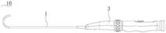
图1是本发明可调弯导管其中一实施例的结构示意图。FIG. 1 is a schematic structural diagram of an embodiment of the adjustable bendable conduit according to the present invention.
图2是图1中可调弯导管的爆炸结构示意图。FIG. 2 is a schematic diagram of an exploded structure of the adjustable bendable conduit in FIG. 1 .
图3是图1中可调弯导管的部分结构示意图。FIG. 3 is a partial structural schematic diagram of the adjustable bendable conduit in FIG. 1 .
图4是图3的第一方向视图。FIG. 4 is a first direction view of FIG. 3 .
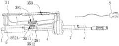
图5是图1中可调弯导管的牵拉钢丝与手柄除去外壳后的爆炸结构示意图。Fig. 5 is a schematic diagram of the explosion structure after the pulling wire and handle of the adjustable bendable conduit in Fig. 1 are removed from the outer casing.
图6是图1中可调弯导管的主轴和牵拉钢丝的结构示意图。FIG. 6 is a schematic structural diagram of the main shaft and the pulling wire of the adjustable bendable catheter in FIG. 1 .
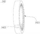
图7是本发明从动环的结构示意图。FIG. 7 is a schematic structural diagram of the driven ring of the present invention.
图8是本发明从动环另一方向的结构示意图。FIG. 8 is a schematic view of the structure of the driven ring of the present invention in another direction.
图9是本发明旋钮的机构示意图。FIG. 9 is a schematic view of the mechanism of the knob of the present invention.
图10是本发明旋钮的另一方向的机构示意图。FIG. 10 is a schematic view of the mechanism of the knob of the present invention in another direction.
图11是限位环的结构示意图。Fig. 11 is a schematic view of the structure of the limit ring.
图12是限位环另一方向的结构示意图。FIG. 12 is a schematic view of the structure of the limit ring in another direction.
图13是滑动件的结构示意图。Fig. 13 is a schematic diagram of the structure of the slider.
图14是滑动件另一方向的结构示意图。Fig. 14 is a schematic view of the structure of the sliding member in another direction.
图15是从动环和旋钮的剖视图。15 is a cross-sectional view of the follower ring and the knob.
图16是本发明中消融系统的结构示意图。FIG. 16 is a schematic structural diagram of the ablation system in the present invention.
图17是图16中部分结构的爆炸图。FIG. 17 is an exploded view of part of the structure in FIG. 16 .
附图标记说明如下:The reference numerals are explained as follows:
10、可调弯导管;1、外鞘管;2、牵拉钢丝;3、手柄;31、外壳;32、主轴;321、出线口;322、第一齿条;331、从动环;3311、延伸块;3312、外凸块;3313、绕线柱;3314、备用柱;3315、定位孔;3316、定位环;3317、同步槽;332、旋钮;3321、第一内凸块;3322、第二内凸块;3323、限位凸块;3324、凹陷部;3326、第一倾斜面;341、滑动件;3411、滑块;3412、杆体;3413、栓柱;3416、第二倾斜面;342、限位环;3421、第二齿条;3422、限位槽;3423、同步凸块;343、第一弹性件;351、固定件;3511、定位柱;3512、容纳槽;352、按钮;3521、第四齿条;353、第三齿条;4、内鞘管;5、三通模块;7、鲁尔接头;9、连接件;10. Adjustable bendable catheter; 1. Outer sheath; 2. Pulling wire; 3. Handle; 31. Housing; 32. Spindle; 321, Outlet; 322, First rack; 331, Driven ring; 3311 , extension block; 3312, outer bump; 3313, winding column; 3314, spare column; 3315, positioning hole; 3316, positioning ring; 3317, synchronization groove; 332, knob; 3321, first inner bump; 3322, 3323, limit bump; 3324, concave part; 3326, first inclined surface; 341, slider; 3411, slider; 3412, rod body; 3413, bolt; 3416, second inclined surface ; 342, limit ring; 3421, second rack; 3422, limit slot; 3423, synchronizing bump; 343, first elastic piece; 351, fixing piece; 3511, positioning post; 3512, accommodating slot; 352, Button; 3521, the fourth rack; 353, the third rack; 4, the inner sheath; 5, the tee module; 7, the Luer connector; 9, the connector;
60、消融机构;60. Ablation institutions;
800、标测装置。800. Mapping device.
具体实施方式Detailed ways
体现本发明特征与优点的典型实施方式将在以下的说明中详细叙述。应理解的是本发明能够在不同的实施方式上具有各种的变化,其皆不脱离本发明的范围,且其中的说明及图示在本质上是当作说明之用,而非用以限制本发明。Exemplary embodiments embodying the features and advantages of the present invention will be described in detail in the following description. It should be understood that the present invention can have various changes in different embodiments without departing from the scope of the present invention, and the descriptions and drawings therein are essentially used for illustration rather than limitation this invention.
本发明提供一种可调弯导管,可用于微创伤介入疗法。该可调弯导管可以依据实际需要而调节远端的弯曲方向及弯曲角度,以满足对可调弯导管的远端形态有不同要求的手术需求。The present invention provides an adjustable bendable catheter, which can be used for minimally invasive interventional therapy. The bendable catheter can adjust the bending direction and bending angle of the distal end according to actual needs, so as to meet the surgical requirements with different requirements for the distal end shape of the bendable catheter.
本发明在描述方位时,以可调弯导管的操作者为参照,靠近操作者的一端为近端,相反的一端则为远端。When describing the orientation of the present invention, the operator of the bendable catheter is used as a reference, the end close to the operator is the proximal end, and the opposite end is the distal end.
参阅图1至图5所示的结构,该可调弯导管10包括外鞘管1、牵拉钢丝2和手柄3。通过对手柄3的操作,以控制牵拉钢丝2的远端向近端移动,从而使外鞘管1的远端弯曲。Referring to the structures shown in FIGS. 1 to 5 , the
外鞘管1呈管状,外鞘管1的侧壁中沿轴向形成有通道。该外鞘管1的远端具有柔性而能够弯曲。具体地,外鞘管1沿轴向包括位于远端的柔性段和连接于柔性段近端的主体段。外鞘管1整体均具有柔性,其中,柔性段的柔性大于主体段的柔性。柔性段弯曲时,能够调整位于其远端端部的医疗组件的轴线的指向,以便将医疗组件输送至目标区域。牵拉钢丝2位于外鞘管1的夹层通道内,优选地,每根牵拉钢丝2容置于一对应的通道中,两个通道关于外鞘管1的轴线对称设置。牵拉钢丝2的远端与外鞘管1的远端固定连接,牵拉钢丝2的近端向外鞘管1的近端延伸,并穿出外鞘管1的近端。The
本实施例中,牵拉钢丝2的数量为两个,两条牵拉钢丝2的远端分别固定在柔性段的相对两侧,以控制外鞘管1的远端能够朝向牵拉钢丝2对应的两个方向进行弯曲。其他实施例中,牵拉钢丝2的数量为一个、三个或其他数量,具体可依据实际而设置。In this embodiment, the number of the pulling
手柄3连接于外鞘管1的近端,用于供操作者操作以调节外鞘管1远端的形态。具体地,手柄3包括外壳31、主轴32、调弯机构和限位机构。The
外壳31的远端与外鞘管1的近端连接。本实施例中,外壳31的截面呈圆形,其内具有容置空间。牵拉钢丝2由外鞘管1的近端穿出后进入外壳31的容置空间内。The distal end of the
具体地,外壳31的外周环设有一凹槽。Specifically, the outer peripheral ring of the
主轴32设置于外壳31的容置空间内。且主轴32的轴向与外壳31的轴向平行,主轴32的外周与外壳31的内壁在径向之间具有间隔。The
参阅图6所示的结构,主轴32呈管状,其内部具有通道。Referring to the structure shown in FIG. 6 , the
主轴32的外周上设有一出线口321,以供牵拉钢丝2穿出。具体地,两牵拉钢丝2进入主轴32的通道后,均由出线口321穿出。本实施例中,出线口321的位置位于主轴32长度方向的中心与远端端点之间的区域,即出线口321靠近远端。A
主轴32的外周上环设有第一齿条322,第一齿条322朝向远端设置。本实施例中,第一齿条322与出线口321之间间隔设置,且第一齿条322设置于出线口321的近端。A
调弯机构与牵拉钢丝2的近端连接,用于调节牵拉钢丝2的远端向近端移动,带动外鞘管1远端的柔性段向一侧弯曲。具体地,调弯机构包括旋钮332和从动环331。The bending mechanism is connected with the proximal end of the pulling
参阅图7和图8,从动环331呈环状,并套设于主轴32的外周,以用于与牵拉钢丝2的近端连接。从动环331能够绕主轴32的轴向转动,也就是沿主轴32的周向转动,从而带动牵拉钢丝2的远端向近端移动。Referring to FIGS. 7 and 8 , the driven
较优地,从动环331上设有两延伸块3311。两延伸块3311沿从动环331的周向间隔设置,且两延伸块3311沿从动环331的轴向延伸。具体在本实施例中,两延伸块3311对称设置。Preferably, the driven
两延伸块3311的设置能够延长了从动环331的轴向长度,从而避免了牵拉钢丝2被从动环331牵拉时,牵拉钢丝2对从动环331的反作用力使从动环331的轴线偏离主轴32的轴线,影响从动环331绕主轴32的转动的问题发生,进而保证了从动环331转动的顺畅。The arrangement of the two
从动环331的外周向外凸设有外凸块3312。本实施例中,外凸块3312的数量为两个,沿从动环331的周向间隔设置。较优地,两外凸块3312在从动环331的外周对称设置。在变更实施方式中,从动环331上外凸块3312的数量为一个。The outer periphery of the driven
较优地,外凸块3312与延伸块3311在从动环331的周向上错位布置,也就是在周向上间隔布置。Preferably, the
从动环331上设有两绕线柱3313,以用于与牵拉钢丝2的近端连接。两绕线柱3313沿从动环331的周向间隔设置,且各绕线柱3313沿主轴32的轴向延伸。其中,绕线柱3313可设置于从动环331的远端面上并凸伸出远端面,也可以设置于从动环331的近端面上凸伸出近端面。绕线柱3313还可以设置于从动环331的周侧表面上。The driven
具体在本实施例中,两绕线柱3313设置于其中一延伸块3311的远端面上,并凸伸出延伸块3311的远端面。Specifically, in this embodiment, the two winding
牵拉钢丝2与从动环331的连接如下:牵拉钢丝2的近端由主轴32的出线口321穿出,并绕主轴32的周向缠绕后,再与绕线柱3313固定。其中,本实施中的两牵拉钢丝2绕主轴32周向上的不同方向缠绕,具体表现为一牵拉钢丝2绕主轴32顺时针方向缠绕,另一牵拉钢丝2绕主轴32周向的逆时针方向缠绕。因此,在从动环331转动时,一个牵拉钢丝2拉紧,另一个牵拉钢丝2放松,且两个牵拉钢丝2的远端固定于外鞘管1的远端的柔性段中,所以,拉紧的牵拉钢丝2的远端带动柔性段向一侧弯曲,放松的牵拉钢丝2的远端所在柔性段一侧跟随弯曲一侧被拉伸,进而使柔性段的远端朝向一个方向弯曲。The connection between the pulling
进一步地,从动环331的外周还设有备用柱3314,用于与绕线柱3313一起固定牵拉钢丝2。例如,牵拉钢丝2在绕线柱3313上缠绕固定难度比较大时,通过绕线柱3313与备用柱3314共同的作用,保证牵拉钢丝2与从动环331之间的牢固的固定。Further, the outer circumference of the driven
备用柱3314与绕线柱3313对应设置,具体表现为,备用柱3314的数量与绕线柱3313相对应,即备用柱3314的数量为两个。并且备用柱3314在从动环331的周向位置也与绕线柱3313对应,即备用柱3314与对应的绕下柱位于同一周向位置。The
备用柱3314的外周沿从动环331的径向向外凸出,且备用柱3314与外凸块3312在周向上错位布置。两备用柱3314在从动环331的外周间隔布置,而使两备用柱3314之间以及两备用柱3314两侧形成了缠绕通道。牵拉钢丝2不仅能够在近端一侧缠绕备用柱3314上,牵拉钢丝2还能够在从动环331的周侧表面上缠绕于备用柱3314上,避免了绕线滑动,减小了绕线难度。The outer circumference of the
备用柱3314在周向上与绕线柱3313对应,绕线柱3313设置于延伸块3311的远端面,因此,本实施例中的备用柱3314由延伸块3311的远端延伸至从动环331的近端。The
牵拉钢丝2缠绕备用柱3314的一种缠绕方法如下:牵拉钢丝2的近端由绕线柱3313进入缠绕通道内,在通道内沿轴向由远端延伸至近端,然后在备用柱3314的近端转折并使牵拉钢丝2沿径向缠绕在备用柱3314的近端面,接着继续转折并使牵拉钢丝2沿轴向由近端延伸至远端,最后回到绕线柱3313处,完成绕备用柱3314一周。具体可以依据实际情况设置缠绕绕线柱3313以及绕备用柱3314的方式。A winding method for the pulling
进一步地,备用柱3314在近端面处超出从动环331,从而使得从动环331的近端也凸伸有两柱子。因此,牵拉钢丝2在缠绕备用柱3314时,其通过缠绕通道后,能够在备用柱3314的近端缠绕于备用柱3314的周向上一周或多周,然后再沿轴向延伸并回到绕线柱3313,从而避免了绕线滑动,加强了牵拉钢丝2与从动环331之间的连接的牢固性。Further, the
在变更实施方式中,绕线柱3313的数量为一个,本实施方式中的两个牵拉钢丝2可以从周向上的不同方向固定于一个绕线柱3313上,调弯效果不受影响。相应地,备用柱3314的数量也可以设置为一个,绕线柱3313与备用柱3314的数量可以不相等,在周向上设置的位置可以不对应。In the modified embodiment, the number of the winding
从动环331上还设有定位孔3315,定位孔3315的轴线平行于从动环331的轴线。具体在本实施例中,定位孔3315数量为两个,并一一对应外凸块3312设置。即定位孔3315与对应的外凸块3312在同一径向上。在变更实施方式中,定位孔3315的轴线与从动环331以及主轴32的轴线不平行,即定位孔3315的延伸方向与轴线之间具有大于0度夹角。并且,定位孔3315的数量可以是一个,或者多于两个的其他数量。另外,定位孔3315可以在周向上与外凸块3312错位设置。The driven
从动环331的近端上还凸设有一定位环3316。该定位环3316的外径小于从动环331的外径,使定位环3316的外周与从动环331的外周之间沿径向具有间隔。具体在本实施例中,定位环3316的内径与从动环331的内径一致。且定位环3316与从动环331一体成型。A
参阅图9和图10所示的结构,旋钮332呈环状,套设于从动环331的外周。旋钮332能够绕主轴32的轴线转动,并带动从动环331转动,进而带动牵拉钢丝2的远端弯曲。Referring to the structure shown in FIG. 9 and FIG. 10 , the
且在轴向上,旋钮332卡置于外壳31的凹槽处。通过该凹槽的卡置作用,使旋钮332能绕轴线方向旋转,但不能沿轴向移动。And in the axial direction, the
旋钮332的内周向内凸设有内凸块。其中,内和外是以旋钮332的使用状态为参照,朝向旋钮332的圆心的方向为内,反之为外。The inner circumference of the
本实施例中,内凸块的数量为四个,四个内凸块沿旋钮332的周向间隔设置。其中,两内凸块为一组,即旋钮332上设有两组内凸块,两组内凸块与从动环331上的两外凸块3312一一对应。In this embodiment, the number of the inner protrusions is four, and the four inner protrusions are arranged at intervals along the circumferential direction of the
每组内凸块包括两个内凸块,分别为第一内凸块3321和第二内凸块3322,第一内凸块3321与第二内凸块3322之间在周向上具有间隔,从而形成一卡槽。Each group of inner bumps includes two inner bumps, namely a first
该旋钮332具有两组内凸块,因此,卡槽的数量为两个。本实施例中,两卡槽沿旋钮332的周向对称设置。The
两卡槽与从动环331的两外凸块3312一一对应。且各卡槽用于卡置一外凸块3312,而使旋钮332在转动时带动从动环331转动。在仅设置一个外凸块3312的实施方式中,旋钮332上设有一组内凸块,形成一卡槽即可。The two locking grooves are in one-to-one correspondence with the two
其中,第一内凸块3321沿周向的长度小于第二内凸块3322沿周向的长度。且两组内凸块在旋钮332的周向上设置时,与第一内凸块3321相邻的是第一内凸块3321和第二内凸块3322,与第二内凸块3322相邻的是第一内凸块3321和第二内凸块3322。Wherein, the length of the first
两卡槽沿旋钮332的周向对称设置,且卡槽由每组的第一内凸块3321和第二内凸块3322之间的间隔形成,因此,在旋钮332的周向上,两个第一内凸块3321之间的距离L1大于两个第二内凸块3322之间的距离L2。The two clamping grooves are symmetrically arranged along the circumferential direction of the
旋钮332在套设于从动环331外周时,从动环331的外凸块3312位于旋钮332对应的卡槽内,从而使旋钮332在顺时针转动或逆时针转动时,外凸块3312与卡槽两侧的第一内凸块3321或第二内凸块3322抵接,进而带动从动环331随旋钮332一起转动。外凸块3312卡置于卡槽中时,从动环331外周的备用柱3314位于两组内凸块之间的间隔中,因此,备用柱3314用于缠绕牵拉钢丝2的功能与外凸块3312带动从动环331随旋钮332转动的功能互不干扰。When the
且备用柱位于两第一内凸块3321之间的间隔内,为牵拉钢丝的缠绕提供充足的空间。And the spare column is located in the space between the two first
旋钮332的内周向内凸设有限位凸块3323。本实施例中,限位凸块3323的数量为四个,四个限位凸块3323沿旋钮332的周向间隔设置。四个限位凸块3323与内凸块一一对应设置。其中,限位凸块3323沿旋钮332的周向的长度小于内凸块的长度。A limiting
具体地,限位凸块3323设置于内凸块的远端面,并与内凸块抵接。且限位凸块3323沿旋钮332的径向方向的尺寸大于内凸块。即限位凸块3323向内超出内凸块。Specifically, the limiting
限位凸块3323的远端面为一倾斜面,定义为第一倾斜面3326。第一倾斜面3326沿顺时针方向从远端向近端延伸。具体表现为,以图9的视图方向为参照,其中一限位凸块3323的第一倾斜面3326的四个端点中,位于下方的端点相对于位于上方的端点更靠近旋钮332的远端。The distal end surface of the limiting
对应一组内凸块的两限位凸块3323上的两个第一倾斜面3326对称设置。具体表现为:两限位凸块3323的第一倾斜面3326之间的周向距离由远至近逐渐减小,即对应一组内凸块的两个第一倾斜面3326的近端沿相互靠近的方向延伸,两限位凸块3323由远端至近端形成一类似口径渐缩的漏斗状。The two first
旋钮332的外周间隔设有多个凹陷部3324,以使操作者便于抓握以及转动旋钮332。限位机构用于在从动环331于一预设角度范围内的转动的过程中,限制外鞘管1保持当前的弯曲状态。具体地,限位机构包括限位环342,第一弹性件343和滑动件341。The outer circumference of the
参阅图11和图12所示的结构,限位环342呈环状,其设置于从动环331的近端。其中,限位环342的近端面环设有第二齿条3421,该第二齿条3421与第一齿条322能够相互啮合,而使限位环342无法沿主轴32的周向转动,实现锁止的功能,以使外鞘管1保持当前的弯曲状态。Referring to the structures shown in FIGS. 11 and 12 , the limiting
其中,从动环331位于限位环342的远端,从动环331的远端面与旋钮332上的限位凸块3323的近端面抵顶,且旋钮332在轴向上的位置是被限制的,因此,限位凸块3323限制了从动环331在轴向上向远端的移动。Wherein, the driven
限位环342的侧壁上设有限位槽3422。其中,限位槽3422的开口朝向限位环342径向的外端。本实施例中,限位槽3422的数量为两个,与从动环331上的定位孔3315对应设置。在变更实施方式中,限位槽3422未在限位环342周侧表面上形成开口,即在限位环342的侧壁中形成完整穿孔。A limiting
限位环342的内径尺寸与定位环3316的外径尺寸相匹配,而使限位环342能够沿轴向移动至套设于定位环3316上,对限位环342的移动起到导向作用。The inner diameter of the limiting
进一步,限位环342的内周还向内凸设有同步凸块3423。定位环3316上还开设有开口朝向近端的同步槽3317。同步槽3317与同步凸块3423对应设置,且同步凸块3423能够卡置于同步槽3317内,使限位环342与从动环331沿周向同步转动,进一步地保证限位环342与从动环331的同步转动。Further, the inner circumference of the limiting
本实施例中,同步凸块3423的数量为两个。两同步凸块3423沿限位环342的周向对称设置。相应地,同步槽3317的数量为两个,沿定位环3316的周向间隔并对称设置。其他实施例中,同步凸块3423的数量还可以为一个、三个或其他数量,具体依据实际而设置。同步槽3317的数量对应同步凸块3423而设置,例如,在同步凸块3423为一个时,同步槽3317的数量也为一个;在同步凸块3423的数量为三个时,同步槽3317的数量也为三个。In this embodiment, the number of the synchronization bumps 3423 is two. The two
第一弹性件343设置于从动环331和限位环342之间,并能够沿轴向伸缩,而使限位环342的第二齿条3421靠近或远离第一齿条322,从而使第二齿条3421与第一齿条322啮合或解除啮合。The first
具体地,第一弹性件343套设于定位环3316的外周,保证第一弹性件343沿轴向伸缩。弹性件可为弹簧,也可以为弹性材料制成的呈环状的结构。Specifically, the first
参阅图13和图14所示的结构,滑动件341插设于从动环331的定位孔3315与限位环342的限位槽3422内,而使限位环342与从动环331沿周向同步转动。具体地,滑动件341包括滑块3411、杆体3412和栓头3413。Referring to the structures shown in FIGS. 13 and 14 , the sliding
杆体3412用于插置于定位孔3315和限位槽3422内。The
滑块3411位于杆体3412的远端,栓头3413位于杆体3412的近端。并且在杆体3412插置于定位孔3315和限位槽3422内时,栓头位于限位环342的近端,以限制杆体3412沿轴向朝远端的移动。具体在本实施例中,杆体3412的近端上设有一插槽,栓头3413插置于插槽内,实现栓头3413与杆体3412之间的可拆卸连接。The
滑动件341与从动环331和限位环342的安装过程如下:杆体3412由远端至近端的方向依次插入定位孔3315和限位槽3422内,再将栓头插置于杆体3412的插槽内,实现三者的安装。The installation process of the
滑块3411呈三角块,且滑块3411在可调弯导管10的正常使用状态时,其宽度沿远端至近端,逐渐减小。滑块3411沿主轴32的径向方向的最小尺寸大于杆体3412的尺寸,同时也大于定位孔3315的直径,而使杆体3412在穿过定位孔3315时,滑块3411无法穿过。The
具体地,滑块3411的截面呈三角形,其中一个顶点用于与杆体3412连接,另外两个顶点与该顶点之间的斜边构成滑块3411的两倾斜面,倾斜面即第二倾斜面3416。第二倾斜面3416由远端至近端逐渐靠近杆体3412。滑块341的两倾斜面3416以杆体为对称轴对称设置,使滑块3411与杆体3412形成一类似Y字形结构。Specifically, the cross-section of the
两个第二斜面与两限位凸块3323的第一倾斜面3326一一对应。第二倾斜面3416和第一倾斜面3326的斜率可以是相同的也可以是不同的。The two second inclined surfaces correspond to the first
在旋钮332转动时,限位凸块3323随之一起转动。限位凸块3323相对于主轴32转动的角度为旋转角度。When the
参阅图15所示的结构,从动环331在备用柱3314的对侧外表面上还设置有一外凸块3312,外凸块3312在周向上占据的圆心角记为α。外凸块3312的周向一侧与对应该侧相邻的内凸块之间在周向上占据的圆心角为预设角度β。旋钮332未旋转时,两内凸块对称分列于外凸块3312的两侧,使外凸块3312于周向上相邻的两内凸块之间的周向距离相同,即外凸块3312分别与相邻的两内凸块之间的预设角度β相同,使外凸块3312顺时针方向和逆时针方向的预设角度β一致,进而使得在旋钮332在周向两侧旋转预设角度β的范围内时,保持外鞘管1远端的弯曲状态。具体在本实施例中,预设角度β为2~15°。卡槽在周向上占据的角度记为γ,且γ=α+2β。Referring to the structure shown in FIG. 15 , the driven
在旋转角度小于预设角度β时,第一倾斜面3326在第二倾斜面3416上滑动,使得第二倾斜面3416相对于第一倾斜面3326向远端运动,使滑块3411带动限位环342沿轴向向远端移动。限位环342向远端移动,并压缩第一弹性件343。此时,限位环342上的第二齿条3421依然与主轴32上的第一齿条322啮合,使限位环342和从动环331无法转动,从而无法拉动牵拉钢丝2,保证了外鞘管1当前的状态,避免了误操作导致的外鞘管1状态的变化。When the rotation angle is smaller than the preset angle β, the first
在旋转角度刚好为预设角度β时,限位环342向远端移动的距离刚好使第二齿条3421与第一齿条322解除啮合。When the rotation angle is just the preset angle β, the distance that the
在旋转角度大于预设角度β时,从动环331的外凸块3312与旋钮332的内凸块在周向上相互抵接,进而使旋钮332带动从动环331和限位环342沿周向转动。When the rotation angle is greater than the preset angle β, the
本实施例中的可调弯导管10的调节原理如下:The adjustment principle of the adjustable
在旋钮332旋转的角度小于预设角度时,从动环331与限位环342处于锁止状态,即不跟随旋钮332转动。此时,限位环342的第二齿条3421与主轴32的第一齿条322相互啮合。旋钮332上的限位凸块3323的第一倾斜面3326将滑块3411的第二倾斜面3416向远端抵顶,使得滑动件341向远端运动,并带动限位环342向远端运动,使第一弹性件343被压缩。其中,旋钮332以及主轴32在轴向上的位置是固定的,从而导致限位环342上的第二齿条3421与主轴32上的第一齿条322之间沿轴向的间隙越来越大。When the rotation angle of the
在旋钮332旋转的角度正好等于预设角度时,限位环342上的第二齿条3421与主轴32上的第一齿条322正好脱开,主轴32与限位环342之间的锁定关系解除。When the rotation angle of the
在旋钮332旋转的角度大于预设角度时,旋钮332的内凸起在周向上抵顶从动环331的外凸起,从而带动从动环331、滑动件341及限位环342转动。从动环331转动,带动牵拉钢丝2的远端向近端移动,而使外鞘管1的远端开始调弯。When the rotation angle of the
在将外鞘管1的远端调节至弯曲程度符合要求后,松开旋钮332,第一弹性件343回复,即第一弹性件343向近端移动,带动滑动件341向近端移动。滑动件341在向近端移动时,其第二倾斜面3416沿第一倾斜面3326向近端滑动,使得滑动件341沿周向转动,从而引起从动环331与限位环342产生回转,回转角度为β,使限位环342的第二齿条3421与主轴32上的第一齿条322啮合,锁止从动环331,进而锁定外鞘管1的远端的弯曲状态。且,回转的角度较小,对手术效果影响较小。After the distal end of the
本实施例中的可调弯导管10通过调弯机构能够调节外鞘管1远端的弯曲方向和弯曲程度,从而能够依据病患的生理解剖结构,在手术现场依据所需的形状而调节外鞘管1的远端,降低了手术的复杂性,保证了手术效果。The
本发明中的可调弯导管10可应用于微创伤介入疗法,例如射频或其他能源的消融术、瓣环环缩术、腹主以及胸腹主动脉瘤腔内修复术。The
本发明还提供一种采用上述可调弯导管10的消融系统和消融装置。The present invention also provides an ablation system and an ablation device using the above-mentioned
参阅图16,消融系统包括标测装置800和消融装置。Referring to Figure 16, the ablation system includes a
消融装置包括消融机构60和可调弯导管10。The ablation device includes an
可调弯导管10在应用于消融装置时,做了更进一步的改进,以下具体介绍。When the
参阅图17所示的结构,手柄3的外壳31上开设有一开口,该开口的长度沿轴向延伸。Referring to the structure shown in FIG. 17 , an opening is formed on the
可调弯导管10的还包括呈管状的内鞘管4,内鞘管4位于外鞘管1内。内鞘管4用于牵拉消融机构60。且内鞘管4的近端穿出外鞘管1的近端,并伸入手柄3内。The
内鞘管4的外径小于外鞘管1的内径,使得内鞘管4和外鞘管1在径向上具有间隔。The outer diameter of the inner sheath tube 4 is smaller than the inner diameter of the
消融机构60包括支撑骨架和设置于支撑骨架上的消融件。支撑骨架的近端与外鞘管1的远端连接,支撑骨架的远端与内鞘管4的远端连接,外鞘管1与内鞘管4在轴向上的相对运动能够使支撑骨架沿其自身径向收缩,进而改变支撑骨架的径向尺寸。The
支撑骨架呈网篮状,包括多个支撑杆。多个支撑杆的远端相互连接,并构成支撑骨架的远端。多个支撑杆的近端相互连接,并构成支撑骨架的近端。各支撑杆能够弯曲,使得支撑杆的远端与近端能够相互靠近或远离,进而能够改变支撑骨架的径向尺寸。The support frame is in the shape of a mesh basket and includes a plurality of support rods. The distal ends of the plurality of support rods are connected to each other and constitute the distal ends of the support frame. The proximal ends of the plurality of support rods are connected to each other and constitute the proximal end of the support frame. Each support rod can be bent, so that the distal end and the proximal end of the support rod can approach or move away from each other, thereby changing the radial dimension of the support frame.
可调弯导管10还包括调径机构,以调节消融机构60在远端的径向尺寸。The
参阅图17所示的结构,调径机构包括固定件351、按钮352、第三齿条353和第二弹性件。Referring to the structure shown in FIG. 17 , the diameter adjusting mechanism includes a fixing
其中,固定件351与内鞘管4的外周固定连接。且固定件351上开设有容纳槽。The fixing
按钮352的底部位于容纳槽内,顶部能够伸出开口。The bottom of the
按钮352沿轴向的长度小于开口沿轴向的开口,且按钮352能在开口内沿轴向移动,进而带动固定件351以及内鞘管4沿轴向移动。The axial length of the
第三齿条353固定于开口的侧壁上。第三齿条353沿径向凸伸处开口的侧壁。The
按钮352上还设有与第三齿条353相互啮合的第四齿条3521。该第四齿条3521设置于按钮352底部,并沿径向凸伸。The
第二弹性件的两端分别抵接按钮352底部和容纳槽的底壁。第二弹性件能够沿径向伸缩而使按钮352能够沿径向移动,从而使第四齿条3521能够脱离第三齿条353或与第三齿条353啮合。其中,第二弹性件沿径向的移动可通过按压操作实现。Two ends of the second elastic member abut against the bottom of the
具体地,第二弹性件为弹簧。Specifically, the second elastic member is a spring.
在第四齿条3521脱离第三齿条353时,按钮352能在开口内沿轴向移动,进而带动固定件351以及内鞘管4沿轴向移动。When the
在第四齿条3521与所述第三齿条353啮合时,按钮352在轴向锁定,固定件351以及内鞘管4在轴向方向锁止。When the
进一步地,固定件351上还设有径向延伸的定位柱3511。定位柱3511设置于容纳槽内。第二弹性件套设于定位柱3511上,以对第二弹性件的伸缩起导向作用。Further, the fixing
本实施例中,第二弹性件的数量为四个,定位柱3511的数量为四个,且定位柱3511在容纳槽内间隔设置。In this embodiment, the number of the second elastic members is four, the number of the
继续参阅图17所示的结构,手柄3的外壳31内还设有一三通模块5。该三通模块5位于固定件351的远端,且三通模块5近端的侧壁包裹在主轴32中,与主轴32分体设置。Continuing to refer to the structure shown in FIG. 17 , a three-
具体地,三通模块5呈空心状,具有一入口和两个出口。三通模块5的入口处连接外鞘管1的近端,外鞘管1的内腔连通三通模块5的内腔。三通模块5远端设置有鲁尔接头7,以及连接件9。外鞘管1中的内鞘管4从三通模块5的入口进入,穿入三通模块5的一个鲁尔接头7中。Specifically, the three-
医生可通过内嵌有内鞘管4的鲁尔接头7向三通模块5内冲注液体,液体在内鞘管4和外鞘管1之间,以及内鞘管4中流动,并从远端的内鞘管4和外鞘管1之间的孔隙,以及内鞘管4的远端流出,通过另一鲁尔接头7排出内鞘管4中的空气。The doctor can inject liquid into the three-
鲁尔接头7、内鞘管4以及电线从三通模块5的远端伸出并穿过外壳31显露在外部,方便操作者从鲁尔接头7注入液体,从而在手术前保证将导管外鞘管1与内鞘管4之间的空气,以及内鞘管4内部的空气排除干净,进一步提高手术的安全性。The luer connector 7, the inner sheath tube 4 and the wires protrude from the distal end of the three-
电线穿过外壳31通过连接件9连接外部电源。The wires pass through the
标测装置800包括标测导管和设置于标测导管远端的标测电极。标测导管用于穿置在手柄3内,标测电极由内鞘管4的远端伸出,以用于贴靠组织壁检测目标组织区域中的电生理信号。The
本实施例中的消融装置和消融系统采用可调弯导管10,从而可以调节远端弯曲方向、弯曲角度以及调节远端消融机构60的径向尺寸,能够满足不同的手术需求。The ablation device and ablation system in this embodiment use an adjustable
由上述技术方案可知,本发明至少具有如下优点和积极效果:As can be seen from the above technical solutions, the present invention at least has the following advantages and positive effects:
本发明的可调弯导管包括外鞘管、牵拉钢丝和手柄,手柄中的调弯机构包括旋钮和从动环,通过旋转旋钮带动从动环转动而控制外鞘管的远端向一侧弯曲,进而能够依据病患的生理解剖结构,在手术现场依据所需的形状而适时调节外鞘管的远端以引导器械到达目标位置,降低了手术的复杂性,保证了手术效果。The adjustable bendable catheter of the present invention includes an outer sheath, a pulling wire and a handle, and the bending mechanism in the handle includes a knob and a driven ring, and the rotating knob drives the driven ring to rotate to control the distal end of the outer sheath to one side By bending, according to the physiological anatomy of the patient, the distal end of the outer sheath can be adjusted in time according to the required shape at the operation site to guide the instrument to the target position, which reduces the complexity of the operation and ensures the operation effect.
虽然已参照几个典型实施方式描述了本发明,但应当理解,所用的术语是说明和示例性、而非限制性的术语。由于本发明能够以多种形式具体实施而不脱离发明的精神或实质,所以应当理解,上述实施方式不限于任何前述的细节,而应在随附权利要求所限定的精神和范围内广泛地解释,因此落入权利要求或其等效范围内的全部变化和改型都应为随附权利要求所涵盖。While the present invention has been described with reference to several exemplary embodiments, it is to be understood that the terminology used is of description and illustration, and not of limitation. Since the invention can be embodied in many forms without departing from the spirit or spirit of the invention, it is to be understood that the above-described embodiments are not limited to any of the foregoing details, but are to be construed broadly within the spirit and scope defined by the appended claims Therefore, all changes and modifications that come within the scope of the claims or their equivalents should be covered by the appended claims.
Claims (21)
Priority Applications (1)
| Application Number | Priority Date | Filing Date | Title |
|---|---|---|---|
| CN202011626219.4ACN112957590B (en) | 2020-12-31 | 2020-12-31 | Ablation system, ablation device and bendable catheter |
Applications Claiming Priority (1)
| Application Number | Priority Date | Filing Date | Title |
|---|---|---|---|
| CN202011626219.4ACN112957590B (en) | 2020-12-31 | 2020-12-31 | Ablation system, ablation device and bendable catheter |
Publications (2)
| Publication Number | Publication Date |
|---|---|
| CN112957590A CN112957590A (en) | 2021-06-15 |
| CN112957590Btrue CN112957590B (en) | 2022-09-27 |
Family
ID=76271620
Family Applications (1)
| Application Number | Title | Priority Date | Filing Date |
|---|---|---|---|
| CN202011626219.4AActiveCN112957590B (en) | 2020-12-31 | 2020-12-31 | Ablation system, ablation device and bendable catheter |
Country Status (1)
| Country | Link |
|---|---|
| CN (1) | CN112957590B (en) |
Families Citing this family (13)
| Publication number | Priority date | Publication date | Assignee | Title |
|---|---|---|---|---|
| CN113662652B (en)* | 2021-08-19 | 2025-08-15 | 上海捍宇医疗科技股份有限公司 | Atrial labyrinth type pulse electric field ablation catheter and equipment thereof |
| CN114082075B (en)* | 2021-09-28 | 2023-07-18 | 四川大学华西医院 | An auxiliary bending control sheath |
| CN114404109B (en)* | 2022-01-25 | 2025-07-25 | 北京领健医疗科技有限公司 | Sheath tube bending adjusting handle, conveying device and valve repair system |
| CN114515192A (en)* | 2022-03-17 | 2022-05-20 | 无锡帕母医疗技术有限公司 | Sheath tube for radiofrequency ablation catheter and radiofrequency ablation catheter |
| CN115192179A (en)* | 2022-06-06 | 2022-10-18 | 绍兴梅奥心磁医疗科技有限公司 | Robot special-shaped bent visual sheath and surgical device |
| CN115969504A (en)* | 2022-09-29 | 2023-04-18 | 中国人民解放军空军军医大学 | A therapeutic needle for percutaneous intraplaque ablation |
| CN115671505B (en)* | 2022-11-01 | 2023-04-28 | 河北康誉医疗器械有限公司 | Contrast guide wire sleeving device |
| CN219439232U (en)* | 2022-12-29 | 2023-08-01 | 先健科技(深圳)有限公司 | An adjustable curved delivery sheath |
| CN116746989A (en)* | 2023-04-14 | 2023-09-15 | 吉林省沃鸿医疗器械制造有限公司 | Disposable ureter guiding sheath |
| CN117084767B (en)* | 2023-08-10 | 2024-05-03 | 中科智博(珠海)科技有限公司 | Spinal endoscope |
| CN221266201U (en)* | 2023-08-10 | 2024-07-05 | 麦迪领先医疗科技(深圳)有限公司 | Adjustable curved sheath pipe adjustment handle |
| CN117179879A (en)* | 2023-09-19 | 2023-12-08 | 上海市胸科医院 | A controllable sheath, a controllable bronchoscope, a mirror-holding arm and an automatic navigation device |
| CN119680081B (en)* | 2025-02-25 | 2025-06-24 | 北京华脉泰科医疗器械股份有限公司 | Adjustable curved guide wire assembly |
Citations (3)
| Publication number | Priority date | Publication date | Assignee | Title |
|---|---|---|---|---|
| CN102580225A (en)* | 2012-02-10 | 2012-07-18 | 先健科技(深圳)有限公司 | adjustable curved sheath |
| CN111743663A (en)* | 2019-03-29 | 2020-10-09 | 上海微创心通医疗科技有限公司 | A handle for delivering implants and its delivery system |
| CN211935126U (en)* | 2019-12-17 | 2020-11-17 | 先健科技(深圳)有限公司 | Adjustable bent sheath tube |
Family Cites Families (5)
| Publication number | Priority date | Publication date | Assignee | Title |
|---|---|---|---|---|
| US7947000B2 (en)* | 2003-09-12 | 2011-05-24 | Intuitive Surgical Operations, Inc. | Cannula system for free-space navigation and method of use |
| US7648519B2 (en)* | 2006-09-13 | 2010-01-19 | Cambridge Endoscopic Devices, Inc. | Surgical instrument |
| US10646340B2 (en)* | 2016-08-19 | 2020-05-12 | Edwards Lifesciences Corporation | Steerable delivery system for replacement mitral valve |
| US10639462B2 (en)* | 2016-10-18 | 2020-05-05 | Acclarent, Inc. | Dilation system |
| US11376401B2 (en)* | 2017-04-26 | 2022-07-05 | Acclarent, Inc. | Deflectable guide for medical instrument |
- 2020
- 2020-12-31CNCN202011626219.4Apatent/CN112957590B/enactiveActive
Patent Citations (3)
| Publication number | Priority date | Publication date | Assignee | Title |
|---|---|---|---|---|
| CN102580225A (en)* | 2012-02-10 | 2012-07-18 | 先健科技(深圳)有限公司 | adjustable curved sheath |
| CN111743663A (en)* | 2019-03-29 | 2020-10-09 | 上海微创心通医疗科技有限公司 | A handle for delivering implants and its delivery system |
| CN211935126U (en)* | 2019-12-17 | 2020-11-17 | 先健科技(深圳)有限公司 | Adjustable bent sheath tube |
Also Published As
| Publication number | Publication date |
|---|---|
| CN112957590A (en) | 2021-06-15 |
Similar Documents
| Publication | Publication Date | Title |
|---|---|---|
| CN112957590B (en) | Ablation system, ablation device and bendable catheter | |
| US10751158B2 (en) | Atrial appendage blood filtration systems | |
| RU2683389C2 (en) | Catheter coupling arrangement | |
| JP2007181702A (en) | Handle system for deploying prosthetic implant | |
| EP3986520A1 (en) | Catheter handle with torque mechanism and valve relief component | |
| JP2012196504A (en) | Method and apparatus for controlling internal circumference of anatomic orifice or lumen | |
| JP7447273B2 (en) | implant delivery system | |
| CN108261256A (en) | Conveying device and transport system | |
| CN113507895B (en) | Device and method for septum puncture | |
| CN110916746B (en) | Pusher and intervene conveying system | |
| CN204814284U (en) | Artificial heart valve conveyor | |
| WO2022256333A2 (en) | Intravascular blood pump | |
| EP4125647A1 (en) | Apparatus and method for septal punch | |
| CN207286181U (en) | Conveying device and transport system | |
| CN106974694A (en) | Medicine equipment actuating station and PCI system, application method | |
| CN213312821U (en) | Catheter sheath and expansion assembly | |
| CN218961553U (en) | Adjustable curved sheath pipe assembly | |
| WO2024212642A1 (en) | Interventional handle assembly having four degrees of freedom | |
| CN114983632B (en) | Bi-directional mobile release heart valve delivery system | |
| CN115105258A (en) | Heart valve delivery system with circumferential limiting mechanism | |
| CN209221308U (en) | A kind of disposable remote-injection syringe of Microendoscopic | |
| CN113545889A (en) | A position control device for an implant | |
| CN216724617U (en) | Guide rail sliding block assembly and operating handle | |
| CN119679546B (en) | Aortic stent graft in situ fenestration system | |
| US20240081991A1 (en) | Systems, devices and methods for delivery systems |
Legal Events
| Date | Code | Title | Description |
|---|---|---|---|
| PB01 | Publication | ||
| PB01 | Publication | ||
| CB02 | Change of applicant information | Address after:310000 room 316, 3 / F, building 2, 88 Jiangling Road, Xixing street, Binjiang District, Hangzhou City, Zhejiang Province Applicant after:Hangzhou DeNO electrophysiological Medical Technology Co.,Ltd. Address before:310000 room 316, 3 / F, building 2, 88 Jiangling Road, Xixing street, Binjiang District, Hangzhou City, Zhejiang Province Applicant before:HANGZHOU NUOMAO MEDICAL TECHNOLOGY Co.,Ltd. | |
| CB02 | Change of applicant information | ||
| SE01 | Entry into force of request for substantive examination | ||
| SE01 | Entry into force of request for substantive examination | ||
| GR01 | Patent grant | ||
| GR01 | Patent grant | ||
| CB03 | Change of inventor or designer information | ||
| CB03 | Change of inventor or designer information | Inventor after:Gao Guoqing Inventor after:Wang Yongsheng Inventor after:Liu Cheng Inventor before:Gao Guoqing Inventor before:Wang Yongsheng | |
| PP01 | Preservation of patent right | ||
| PP01 | Preservation of patent right | Effective date of registration:20250313 Granted publication date:20220927 | |
| PD01 | Discharge of preservation of patent | ||
| PD01 | Discharge of preservation of patent | Date of cancellation:20250605 Granted publication date:20220927 | |
| PE01 | Entry into force of the registration of the contract for pledge of patent right | ||
| PE01 | Entry into force of the registration of the contract for pledge of patent right | Denomination of invention:Ablation system, ablation device, and adjustable bend catheter Granted publication date:20220927 Pledgee:Shanghai Chenyao Xinchen Private Equity Investment Fund Partnership Enterprise (L.P.) Pledgor:Hangzhou DeNO electrophysiological Medical Technology Co.,Ltd. Registration number:Y2025980023298 |