CN112945130B - Ultrafast Microscopic Imaging System for Simultaneous Acquisition of Depth and Surface Information - Google Patents
Ultrafast Microscopic Imaging System for Simultaneous Acquisition of Depth and Surface InformationDownload PDFInfo
- Publication number
- CN112945130B CN112945130BCN202110152804.3ACN202110152804ACN112945130BCN 112945130 BCN112945130 BCN 112945130BCN 202110152804 ACN202110152804 ACN 202110152804ACN 112945130 BCN112945130 BCN 112945130B
- Authority
- CN
- China
- Prior art keywords
- coupler
- sample
- signal
- spectral
- laser
- Prior art date
- Legal status (The legal status is an assumption and is not a legal conclusion. Google has not performed a legal analysis and makes no representation as to the accuracy of the status listed.)
- Active
Links
- 238000003384imaging methodMethods0.000titleclaimsabstractdescription33
- 239000002609mediumSubstances0.000claimsabstractdescription26
- 238000012545processingMethods0.000claimsabstractdescription13
- 239000002612dispersion mediumSubstances0.000claimsabstractdescription11
- 230000003595spectral effectEffects0.000claimsdescription65
- 230000003287optical effectEffects0.000claimsdescription16
- 239000006185dispersionSubstances0.000claimsdescription14
- 238000001228spectrumMethods0.000claimsdescription14
- 238000005070samplingMethods0.000claimsdescription10
- 238000002310reflectometryMethods0.000claimsdescription8
- 230000009466transformationEffects0.000claimsdescription8
- 230000003111delayed effectEffects0.000claimsdescription7
- 230000010287polarizationEffects0.000claimsdescription7
- 230000005540biological transmissionEffects0.000claimsdescription3
- 238000006243chemical reactionMethods0.000claimsdescription3
- 230000001934delayEffects0.000claimsdescription3
- 238000012014optical coherence tomographyMethods0.000description16
- 238000005516engineering processMethods0.000description13
- 238000000034methodMethods0.000description7
- 238000010586diagramMethods0.000description5
- 230000008569processEffects0.000description4
- 238000005259measurementMethods0.000description3
- 230000008859changeEffects0.000description2
- 238000010276constructionMethods0.000description2
- 230000006978adaptationEffects0.000description1
- 238000004458analytical methodMethods0.000description1
- 238000003491arrayMethods0.000description1
- 230000009286beneficial effectEffects0.000description1
- 238000007796conventional methodMethods0.000description1
- 230000008878couplingEffects0.000description1
- 238000010168coupling processMethods0.000description1
- 238000005859coupling reactionMethods0.000description1
- 238000001514detection methodMethods0.000description1
- 239000000835fiberSubstances0.000description1
- 230000001678irradiating effectEffects0.000description1
- 238000012986modificationMethods0.000description1
- 230000004048modificationEffects0.000description1
Images

Classifications
- G—PHYSICS
- G01—MEASURING; TESTING
- G01B—MEASURING LENGTH, THICKNESS OR SIMILAR LINEAR DIMENSIONS; MEASURING ANGLES; MEASURING AREAS; MEASURING IRREGULARITIES OF SURFACES OR CONTOURS
- G01B11/00—Measuring arrangements characterised by the use of optical techniques
- G01B11/22—Measuring arrangements characterised by the use of optical techniques for measuring depth
- G—PHYSICS
- G01—MEASURING; TESTING
- G01B—MEASURING LENGTH, THICKNESS OR SIMILAR LINEAR DIMENSIONS; MEASURING ANGLES; MEASURING AREAS; MEASURING IRREGULARITIES OF SURFACES OR CONTOURS
- G01B9/00—Measuring instruments characterised by the use of optical techniques
- G01B9/02—Interferometers
- G01B9/02041—Interferometers characterised by particular imaging or detection techniques
Landscapes
- Physics & Mathematics (AREA)
- General Physics & Mathematics (AREA)
- Investigating Or Analysing Materials By Optical Means (AREA)
Abstract
Description
Translated fromChinese技术领域technical field
本发明属于超快显微成像领域,具体涉及一种同时获得深度和表面信息的超快显微成像系统。The invention belongs to the field of ultrafast microscopic imaging, and in particular relates to an ultrafast microscopic imaging system for simultaneously obtaining depth and surface information.
背景技术Background technique
超快成像主要有两种,一种是利用棱镜、光栅等一维衍射器件对超快激光进行一维衍射,从而对待测样品进行线扫描,另一种是采用光栅和虚拟相位阵列结合的方式对超快激光进行二维衍射,从而对待测样品进行面扫描。虽然该方法在显微成像领域有较好的应用前景但是无法获得待测样品的深度信息。而目前测量待测样品的深度信息通常采用光相干层析(OCT)技术,该技术是将光脉冲集中照射到待测样品的一点上,待测样品上该点接收到光脉冲后返回反射光,根据反射光中干涉光谱自由光谱范围(FSR)的变化来反映样品的深度信息,虽然该技术可以获得样品的深度信息,但是如果想得到整个样品的三维图像则需要对待测样品进行逐点扫描,从而降低了系统的有效帧率。There are two main types of ultrafast imaging, one is to use one-dimensional diffraction devices such as prisms and gratings to perform one-dimensional diffraction on ultrafast lasers, so as to perform line scanning on the sample to be tested, and the other is to use a combination of gratings and virtual phase arrays. Two-dimensional diffraction of ultrafast laser light to surface scan the sample to be measured. Although this method has good application prospects in the field of microscopic imaging, the depth information of the sample to be tested cannot be obtained. At present, optical coherence tomography (OCT) technology is usually used to measure the depth information of the sample to be tested. This technology is to irradiate a light pulse to a point of the sample to be tested, and then the point on the sample to be tested receives the light pulse and returns the reflected light. , and reflect the depth information of the sample according to the change of the interference spectrum free spectral range (FSR) in the reflected light. Although this technique can obtain the depth information of the sample, if you want to obtain a three-dimensional image of the entire sample, you need to scan the sample point by point. This reduces the effective frame rate of the system.
发明内容SUMMARY OF THE INVENTION
本发明提供一种同时获得深度和表面信息的超快显微成像系统,以解决目前无法利用同一激光信号同时获得待测样品深度和表面信息的问题。The present invention provides an ultrafast microscopic imaging system that simultaneously obtains depth and surface information, so as to solve the problem that the same laser signal cannot be used to obtain the depth and surface information of a sample to be tested at the same time.
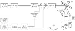
根据本发明实施例的第一方面,提供一种同时获得深度和表面信息的超快显微成像系统,包括激光发生器,所述激光发生器的输出端通过色散介质连接第一耦合器的输入端,所述第一耦合器的第一输出端连接环形器的第一端,所述环形器的第二端连接准直器的第一端,所述准直器的第二端与衍射器件的第一输入/输出端对准,所述衍射器件的第二输入/输出端与平凸透镜的平面对准,所述平凸透镜的凸面与待测样品对准,所述环形器的第三端与第二耦合器的第一输入端连接,所述第一耦合器的第二输出端通过可调延迟介质与所述第二耦合器的第二输入端连接,所述第二耦合器的输出端连接探测器的输入端,所述探测器的输出端连接高速示波器的输入端,所述高速示波器的输出端连接信号处理模块;According to a first aspect of the embodiments of the present invention, an ultrafast microscopic imaging system for simultaneously obtaining depth and surface information is provided, including a laser generator, an output end of the laser generator is connected to an input of a first coupler through a dispersive medium The first output end of the first coupler is connected to the first end of the circulator, the second end of the circulator is connected to the first end of the collimator, and the second end of the collimator is connected to the diffraction device The first input/output end of the diffractive device is aligned with the plane of the plano-convex lens, the convex surface of the plano-convex lens is aligned with the sample to be tested, and the third end of the circulator is connected to the first input end of the second coupler, the second output end of the first coupler is connected to the second input end of the second coupler through an adjustable delay medium, and the output end of the second coupler The end is connected to the input end of the detector, the output end of the detector is connected to the input end of the high-speed oscilloscope, and the output end of the high-speed oscilloscope is connected to the signal processing module;
所述色散介质对所述激光发生器产生的激光信号在时域上进行拉伸,所述第一耦合器将拉伸后的激光信号分成两路,其中一路激光信号依次通过所述环形器、准直器传输给所述衍射器件,该路激光信号经由所述衍射器件产生具有不同衍射路径的衍射光,各个具有不同衍射路径的衍射光通过所述平凸透镜转换为多个平行光,所述多个平行光照射到所述待测样品的不同位置处,所述待测样品的对应位置在接收到平行光后产生反射光,且该对应位置处的反射率被编码到所述反射光的光谱中,所述反射光沿着原传输路径,依次通过所述平凸透镜、衍射器件和准直器传输给所述环形器;所述环形器将所述反射光传输给所述第二耦合器;The dispersive medium stretches the laser signal generated by the laser generator in the time domain, and the first coupler divides the stretched laser signal into two paths, wherein one laser signal passes through the circulator, The collimator is transmitted to the diffractive device, and the laser signal of this route generates diffracted light with different diffraction paths through the diffractive device, and each diffracted light with different diffraction paths is converted into a plurality of parallel lights through the plano-convex lens, and the Multiple parallel lights irradiate different positions of the sample to be tested, the corresponding position of the sample to be tested generates reflected light after receiving the parallel light, and the reflectivity at the corresponding position is encoded into the reflected light. In the spectrum, the reflected light is transmitted to the circulator through the plano-convex lens, the diffraction device and the collimator in sequence along the original transmission path; the circulator transmits the reflected light to the second coupler ;
所述可调延迟介质对所述第一耦合器分成的另一路激光信号进行延迟处理,以与返回的所述反射光进行光程匹配,延迟处理后的该另一路激光信号作为参考光被传输给所述第二耦合器;所述反射光与参考光在所述第二耦合器处发生干涉,产生反射光干涉信号,所述探测器对所述反射光干涉信号进行探测,生成电信号;所述高速示波器对所述电信号进行模数转换,生成数字信号;The adjustable delay medium performs delay processing on another laser signal divided by the first coupler to match the optical path of the returned reflected light, and the delayed laser signal is transmitted as a reference light to the second coupler; the reflected light and the reference light interfere at the second coupler to generate a reflected light interference signal, and the detector detects the reflected light interference signal to generate an electrical signal; The high-speed oscilloscope performs analog-to-digital conversion on the electrical signal to generate a digital signal;
所述信号处理模块根据所述数字信号的光谱强度,来确定所述待测样品在对应位置处的反射率,从而确定该对应位置处的表面信息,并且对所述数字信号进行傅里叶变化,根据傅里叶变化后数字信号的自由光谱范围,来确定所述待测样品在对应位置处的深度信息。The signal processing module determines the reflectivity of the sample to be tested at the corresponding position according to the spectral intensity of the digital signal, so as to determine the surface information at the corresponding position, and performs Fourier transformation on the digital signal. , and according to the free spectral range of the digital signal after Fourier transformation, the depth information of the sample to be tested at the corresponding position is determined.
在一种可选的实现方式中,还包括步进电机,设各个平行光所在的同一平面为第一平面,X轴位于该第一平面上且与各个平行光垂直,Z轴与各个平行光平行,Y轴同时垂直于该X轴和Z轴,所述待测样品位于各个平行光中至少部分平行光的正下方,以使对应平行光对所述待测样品进行X轴方向上的线扫描,所述步进电机带动所述待测样品沿着所述Y轴方向移动,从而对所述待测样品进行X-Y两个维度的面扫描。In an optional implementation manner, a stepping motor is also included, and the same plane where each parallel light is located is a first plane, the X axis is located on the first plane and is perpendicular to each parallel light, and the Z axis is parallel to each parallel light. Parallel, the Y-axis is perpendicular to the X-axis and the Z-axis at the same time, and the sample to be tested is located directly below at least part of the parallel light in each parallel light, so that the corresponding parallel light can perform a line in the X-axis direction on the sample to be tested. Scanning, the stepper motor drives the sample to be tested to move along the direction of the Y axis, so as to perform a surface scan of the sample to be tested in two dimensions of X-Y.
在另一种可选的实现方式中,还包括光放大器,所述色散介质通过所述光放大器与所述第一耦合器的输入端连接。In another optional implementation manner, an optical amplifier is further included, and the dispersion medium is connected to the input end of the first coupler through the optical amplifier.
在另一种可选的实现方式中,还包括偏振控制器,所述环形器的第三端通过所述偏振控制器与所述第二耦合器的第二输入端连接。In another optional implementation manner, a polarization controller is further included, and the third end of the circulator is connected to the second input end of the second coupler through the polarization controller.
在另一种可选的实现方式中,所述激光信号的一个周期内包括多个具有不同波长的光谱成本。In another optional implementation manner, one cycle of the laser signal includes a plurality of spectral costs with different wavelengths.
在另一种可选的实现方式中,所述激光发生器为超快激光器,所述激光信号的光谱范围为十几纳米级,脉冲重复频率大于兆赫兹。In another optional implementation manner, the laser generator is an ultrafast laser, the spectral range of the laser signal is in the order of tens of nanometers, and the pulse repetition frequency is greater than megahertz.
在另一种可选的实现方式中,所述可调延迟介质根据波长大小,对所述激光信号中具有不同波长的光谱成分分别进行延迟处理,以实现延迟处理后的光谱成分与返回的反射光之间的光程匹配。In another optional implementation manner, the tunable delay medium respectively delays spectral components with different wavelengths in the laser signal according to the size of the wavelength, so as to realize the delayed spectral components and the returned reflection. Optical path matching between lights.
在另一种可选的实现方式中,所述系统的视场大小由衍射器件的色散能力,显微物镜的焦距和激光信号光谱带宽共同决定。In another optional implementation manner, the size of the field of view of the system is jointly determined by the dispersion capability of the diffractive device, the focal length of the microscope objective and the spectral bandwidth of the laser signal.
在另一种可选的实现方式中,所述系统的波长分辨能力由以下几个因素决定:一是色散介质的色散能力,二是色散傅里叶变换(DFT)的光谱分辨能力,三是探测器、高速示波器的带宽决定的光谱分辨能力,系统最终的光谱分辨能力由以上三个参数中最大的决定。In another optional implementation manner, the wavelength resolution capability of the system is determined by the following factors: firstly, the dispersion capability of the dispersive medium; secondly, the spectral resolution capability of the dispersive Fourier transform (DFT); thirdly, the The spectral resolution is determined by the bandwidth of the detector and the high-speed oscilloscope. The final spectral resolution of the system is determined by the largest of the above three parameters.
在另一种可选的实现方式中,所述系统的成像帧率由光源的脉冲频率决定,通常超快激光的脉冲频率大于兆赫兹;成像的有效帧率还取决于待测样品在Y轴的移动速度;图像的像素点由激光信号的光谱宽度,色散介质的色散系数和高速示波器的采样率决定。In another optional implementation manner, the imaging frame rate of the system is determined by the pulse frequency of the light source, usually the pulse frequency of the ultrafast laser is greater than megahertz; the effective frame rate of the imaging also depends on the Y-axis of the sample to be tested. The moving speed of the image is determined by the spectral width of the laser signal, the dispersion coefficient of the dispersion medium and the sampling rate of the high-speed oscilloscope.
本发明的有益效果是:The beneficial effects of the present invention are:
1、本发明利用同一激光信号就可同时对待测样品的深度和表面信息进行测量,通过色散傅里叶变换(DFT)技术记录光谱,相比于传统的光谱仪具有在保证光谱分辨率的同时可以将光谱信息用探测器直接采集,从而将采样率提升至兆赫兹;利用超快激光器可以保证一个脉冲既可以包含高达几十纳米的光谱信息相比传统的光相干层析(OCT)具有更宽的扫描范围,此外由于超快激光器具有兆赫兹的重复频率从而可以保证成像系统具有更高的成像帧率;采用衍射光栅来进行色散的方式可以使空间位置和光谱相对应,从而可以用反射光的光谱强度反应样品不同空间位置的信息;1. The present invention can simultaneously measure the depth and surface information of the sample to be tested by using the same laser signal, and record the spectrum through the Dispersive Fourier Transform (DFT) technology. The spectral information is directly collected by the detector, thereby increasing the sampling rate to megahertz; the use of ultrafast lasers can ensure that a pulse can contain spectral information up to tens of nanometers, which is wider than traditional optical coherence tomography (OCT) In addition, because the ultrafast laser has a repetition frequency of megahertz, it can ensure that the imaging system has a higher imaging frame rate; using a diffraction grating for dispersion can make the spatial position and spectrum correspond, so that reflected light can be used. The spectral intensity reflects the information of different spatial positions of the sample;
2、本发明在衍射器件与待测样品之间增加了平凸透镜,使得不同衍射角的衍射光都垂直入射到待测样品上,由此垂直入射到待测样品的各个平行光均与唯一的X轴坐标对应,此外由于不同波长的光入射到衍射器件后,其衍射角是固定的,因此当衍射器件与平凸透镜之间的位置关系确定时,各个平行光与X轴坐标的关系也固定,根据返回的反射光的波长大小,可以识别出是该反射光从待测样品上哪个X坐标位置处返回的;本发明在进行深度信息测量时,并不是针对每个平行光设置分束光,而是设置可调延迟介质,使可调延迟介质根据波长大小,对所述激光信号中具有不同波长的光谱成分分别进行延迟处理,从而实现延迟处理后的光谱成分与返回的反射光之间的光程匹配,由此不仅可以降低多点深度测量的搭建成本,而且即便激光信号中光谱成分的波长大小发生变化,也不需要对传统设置的分束器的位置进行分别调节,适应能力较强;本发明在将激光信号传输给第一耦合器之前,还通过色散介质对激光信号在时域上进行拉伸(该过程将光谱和光脉冲相对应),相比于传统的光谱仪具有在保证光谱分辨率的同时可以将光谱信息用探测器直接采集,从而将采样率提升至兆赫兹;2. In the present invention, a plano-convex lens is added between the diffraction device and the sample to be tested, so that diffracted lights with different diffraction angles are vertically incident on the sample to be tested, so that each parallel light vertically incident to the sample to be tested is the same as the unique one. The X-axis coordinates correspond. In addition, since light of different wavelengths is incident on the diffractive device, its diffraction angle is fixed. Therefore, when the positional relationship between the diffractive device and the plano-convex lens is determined, the relationship between each parallel light and the X-axis coordinate is also fixed. , according to the wavelength of the returned reflected light, it can be identified from which X-coordinate position on the sample to be tested the reflected light returned; when the present invention measures depth information, it is not for each parallel light to set a split beam , but set an adjustable delay medium, so that the adjustable delay medium can delay the spectral components with different wavelengths in the laser signal according to the wavelength, so as to realize the difference between the delayed spectral components and the returned reflected light. It can not only reduce the construction cost of multi-point depth measurement, but also do not need to adjust the position of the traditional beam splitter separately even if the wavelength of the spectral components in the laser signal changes, so the adaptability is relatively high. Strong; before transmitting the laser signal to the first coupler, the present invention also stretches the laser signal in the time domain through the dispersive medium (this process corresponds to the spectrum and the light pulse), compared with the traditional spectrometer, it has the guarantee of With spectral resolution, spectral information can be directly collected with detectors, thereby increasing the sampling rate to megahertz;
3、本发明还设置有步进电机,所述待测样品位于各个平行光中至少部分平行光的正下方,以使对应平行光对所述待测样品进行X轴方向上的线扫描,所述步进电机带动所述待测样品沿着所述Y轴方向移动,从而对所述待测样品进行X-Y两个维度的面扫描。3. The present invention is also provided with a stepping motor, and the sample to be tested is located directly below at least part of the parallel light in each parallel light, so that the corresponding parallel light performs line scanning on the sample to be tested in the X-axis direction, so The stepper motor drives the sample to be tested to move along the direction of the Y-axis, so that the sample to be tested is scanned in two dimensions of X-Y.
附图说明Description of drawings
图1是本发明同时获得深度和表面信息的超快显微成像系统的一个实施例结构示意图;1 is a schematic structural diagram of an embodiment of an ultrafast microscopic imaging system for simultaneously obtaining depth and surface information according to the present invention;
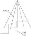
图2是衍射器件输出衍射光入射到待测样品上的示意图;Fig. 2 is the schematic diagram that the diffraction device output diffracted light is incident on the sample to be tested;
图3是本发明同时获得深度和表面信息的超快显微成像系统的另一个实施例结构示意图。FIG. 3 is a schematic structural diagram of another embodiment of the ultrafast microscopic imaging system for simultaneously obtaining depth and surface information according to the present invention.
具体实施方式Detailed ways
为了使本技术领域的人员更好地理解本发明实施例中的技术方案,并使本发明实施例的上述目的、特征和优点能够更加明显易懂,下面结合附图对本发明实施例中技术方案作进一步详细的说明。In order for those skilled in the art to better understand the technical solutions in the embodiments of the present invention, and to make the above objects, features, and advantages of the embodiments of the present invention more clearly understood, the following describes the technical solutions in the embodiments of the present invention with reference to the accompanying drawings. for further details.
在本发明的描述中,除非另有规定和限定,需要说明的是,术语“连接”应做广义理解,例如,可以是机械连接或电连接,也可以是两个元件内部的连通,可以是直接相连,也可以通过中间媒介间接相连,对于本领域的普通技术人员而言,可以根据具体情况理解上述术语的具体含义。In the description of the present invention, unless otherwise specified and limited, it should be noted that the term "connection" should be understood in a broad sense. It is directly connected or indirectly connected through an intermediate medium. For those skilled in the art, the specific meanings of the above terms can be understood according to specific situations.
参见图1,为本发明同时获得深度和表面信息的超快显微成像系统的一个实施例结构示意图。该系统可以包括激光发生器,所述激光发生器的输出端通过色散介质连接第一耦合器的输入端,所述第一耦合器的第一输出端连接环形器的第一端,所述环形器的第二端连接准直器的第一端,所述准直器的第二端与衍射器件的第一输入/输出端对准,所述衍射器件的第二输入/输出端与平凸透镜的平面对准,所述平凸透镜的凸面与待测样品对准,所述环形器的第三端与第二耦合器的第一输入端连接,所述第一耦合器的第二输出端通过可调延迟介质与所述第二耦合器的第二输入端连接,所述第二耦合器的输出端连接探测器的输入端,所述探测器的输出端连接高速示波器的输入端,所述高速示波器的输出端连接信号处理模块。Referring to FIG. 1 , it is a schematic structural diagram of an embodiment of an ultrafast microscopic imaging system for simultaneously obtaining depth and surface information according to the present invention. The system may include a laser generator, the output end of the laser generator is connected to the input end of the first coupler through the dispersive medium, the first output end of the first coupler is connected to the first end of the circulator, the ring The second end of the collimator is connected to the first end of the collimator, the second end of the collimator is aligned with the first input/output end of the diffractive device, and the second input/output end of the diffractive device is aligned with the plano-convex lens The plane of the plano-convex lens is aligned with the sample to be tested, the third end of the circulator is connected to the first input end of the second coupler, and the second output end of the first coupler passes through The adjustable delay medium is connected to the second input end of the second coupler, the output end of the second coupler is connected to the input end of the detector, the output end of the detector is connected to the input end of the high-speed oscilloscope, the The output end of the high-speed oscilloscope is connected to the signal processing module.
所述色散介质对所述激光发生器产生的激光信号在时域上进行拉伸,所述第一耦合器将拉伸后的激光信号分成两路,其中一路激光信号依次通过所述环形器、准直器传输给所述衍射器件,该路激光信号经由所述衍射器件产生具有不同衍射路径的衍射光,各个具有不同衍射路径的衍射光通过所述平凸透镜转换为多个平行光,所述多个平行光照射到所述待测样品的不同位置处,所述待测样品的对应位置在接收到平行光后产生反射光,且该对应位置处的反射率被编码到所述反射光的光谱中,所述反射光沿着原传输路径,依次通过所述平凸透镜、衍射器件和准直器传输给所述环形器;所述环形器将所述反射光传输给所述第二耦合器。The dispersive medium stretches the laser signal generated by the laser generator in the time domain, and the first coupler divides the stretched laser signal into two paths, wherein one laser signal passes through the circulator, The collimator is transmitted to the diffractive device, and the laser signal of this route generates diffracted light with different diffraction paths through the diffractive device, and each diffracted light with different diffraction paths is converted into a plurality of parallel lights through the plano-convex lens, and the Multiple parallel lights irradiate different positions of the sample to be tested, the corresponding position of the sample to be tested generates reflected light after receiving the parallel light, and the reflectivity at the corresponding position is encoded into the reflected light. In the spectrum, the reflected light is transmitted to the circulator through the plano-convex lens, the diffraction device and the collimator in sequence along the original transmission path; the circulator transmits the reflected light to the second coupler .
所述可调延迟介质对所述第一耦合器分成的另一路激光信号进行延迟处理,以与返回的所述反射光进行光程匹配,延迟处理后的该另一路激光信号作为参考光被传输给所述第二耦合器;所述反射光与参考光在所述第二耦合器处发生干涉,产生反射光干涉信号,所述探测器对所述反射光干涉信号进行探测,生成电信号;所述高速示波器对所述电信号进行模数转换,生成数字信号;所述信号处理模块根据所述数字信号的光谱强度,来确定所述待测样品在对应位置处的反射率,从而确定该对应位置处的表面信息,并且对所述数字信号进行傅里叶变化,根据傅里叶变化后数字信号对应的自由光谱范围,来确定所述待测样品在对应位置处的深度信息。The adjustable delay medium performs delay processing on another laser signal divided by the first coupler to match the optical path of the returned reflected light, and the delayed laser signal is transmitted as a reference light to the second coupler; the reflected light and the reference light interfere at the second coupler to generate a reflected light interference signal, and the detector detects the reflected light interference signal to generate an electrical signal; The high-speed oscilloscope performs analog-to-digital conversion on the electrical signal to generate a digital signal; the signal processing module determines the reflectivity of the sample to be measured at the corresponding position according to the spectral intensity of the digital signal, so as to determine the The surface information at the corresponding position is obtained, and the digital signal is subjected to Fourier transformation, and the depth information of the sample to be tested at the corresponding position is determined according to the free spectral range corresponding to the digital signal after the Fourier transformation.
本实施例中,由于入射光入射至衍射器件后,从衍射器件输出的衍射光的衍射角与入射光的波长有关,也就是说不同波长的入射光,其对应从衍射器件中射出的衍射光的衍射路径各不相同,因此无论在现有技术的超快成像中,还是在本发明中,激光发生器产生的激光信号的一个周期内都包括多个具有不同波长的光谱成分,以便对待测样品进行线扫描,其中设各个平行光所在的同一平面为第一平面,X轴位于该第一平面上且与各个平行光垂直,Z轴与各个平行光平行,Y轴同时垂直于该X轴和Z轴。此外,现有光相干层析(OCT)技术是将光脉冲集中照射到待测样品的一点上,待测样品上该点接收到光脉冲后返回反射光,根据反射光中干涉光谱自由光谱范围(FSR)的变化来反映样品的深度信息。由于现有的超快成像技术已经可以对待测样品的线扫描,在此过程中有多个点作用于待测样品上,本领域技术人员在将现有的超快成像技术和光相干层析(OCT)技术相结合时,通常会想到直接利用现有超快成像技术中待测样品上多个点返回的反射光对各个点的深度进行检测,从而提高待测样品上单次检测到深度信息的点的个数。但是结合图2所示,当待测样品中从左到右的第二阶梯如实线所示,则衍射光与待测样品中的A点相交,当待测样品中第二阶梯如虚线所示,则衍射光与待测样品中的B点相交,A点和B点在待测样品上的位置不同,可见若直接利用现有超快成像技术中待测样品上返回的反射光对深度进行检测,同一衍射光无法对不同待测样品在相同X轴坐标处的深度进行测量。为此,本发明在衍射器件与待测样品之间增加了平凸透镜,使得不同衍射角的衍射光都垂直入射到待测样品上,由此垂直入射到待测样品的各个平行光均与唯一的X轴坐标对应,此外由于不同波长的光入射到衍射器件后,其衍射角是固定的,因此当衍射器件与平凸透镜之间的位置关系确定时,各个平行光与X轴坐标的关系也固定,根据返回的反射光的波长大小,可以识别出是该反射光从待测样品上哪个X坐标位置处返回的。In this embodiment, since the incident light is incident on the diffractive device, the diffraction angle of the diffracted light output from the diffractive device is related to the wavelength of the incident light, that is to say, the incident light of different wavelengths corresponds to the diffracted light emitted from the diffractive device The diffraction paths are different, so no matter in the ultrafast imaging of the prior art or in the present invention, one cycle of the laser signal generated by the laser generator includes a plurality of spectral components with different wavelengths, so as to be tested. The sample is subjected to line scanning, wherein the same plane where each parallel light is located is the first plane, the X axis is located on the first plane and is perpendicular to each parallel light, the Z axis is parallel to each parallel light, and the Y axis is perpendicular to the X axis at the same time and Z axis. In addition, the existing optical coherence tomography (OCT) technology focuses on irradiating a light pulse on a point of the sample to be tested, and the point on the sample to be tested receives the light pulse and returns the reflected light, according to the free spectral range of the interference spectrum in the reflected light (FSR) changes to reflect the depth information of the sample. Since the existing ultrafast imaging technology can already scan the line of the sample to be tested, there are multiple points acting on the sample to be tested during this process. Those skilled in the art are combining the existing ultrafast imaging technology and optical coherence tomography ( When combined with OCT) technology, it is usually thought to directly use the reflected light returned from multiple points on the sample to be tested in the existing ultrafast imaging technology to detect the depth of each point, so as to improve the depth information detected on the sample to be tested for a single time. the number of points. However, as shown in Figure 2, when the second step from left to right in the sample to be tested is shown as a solid line, the diffracted light intersects point A in the sample to be tested, and when the second step in the sample to be tested is shown as a dotted line , then the diffracted light intersects point B in the sample to be tested, and the positions of point A and point B on the sample to be tested are different. It can be seen that if the reflected light returned from the sample to be tested in the existing ultrafast imaging technology is directly used for depth analysis Detection, the same diffracted light cannot measure the depth of different samples to be tested at the same X-axis coordinate. To this end, the present invention adds a plano-convex lens between the diffraction device and the sample to be tested, so that diffracted lights with different diffraction angles are vertically incident on the sample to be tested, so that each parallel light vertically incident to the sample to be tested is the same as the unique The X-axis coordinates correspond to , and since the diffraction angles of different wavelengths of light incident on the diffractive device are fixed, when the positional relationship between the diffractive device and the plano-convex lens is determined, the relationship between each parallel light and the X-axis coordinates is also Fixed, according to the wavelength of the returned reflected light, it can be identified from which X-coordinate position on the sample to be tested the reflected light returned.
另外,现有光相干层析(OCT)技术是将入射到待测样品上的光信号进行分束,将一部分传输给待测样品,一部分传输给参考镜,如果按照这种方法,针对每个平行光都要设置对应的分束器,显然设置成本较高,且一旦激光信号中光谱成分的波长发生改变,分束器的位置也需要分别进行调节,操作复杂,适应能力较差,为此本发明设置了可调延迟介质。当位于平凸透镜之下的水平台面上未放置待测样品,各个水平光直接入射到水平台面上时,在衍射器件、平凸透镜和水平台面之间位置固定的前提下,针对激光信号中每个光谱成分,该衍射器件接收到对应波长的光谱成分后,输出的衍射光、平行光和返回的反射光的光程固定,因此本发明中可调延迟介质根据波长大小,对所述激光信号中具有不同波长的光谱成分分别进行延迟处理,可以实现延迟处理后的光谱成分与返回的反射光之间的光程匹配。本发明在进行深度信息测量时,并不是针对每个平行光设置分束光,而是设置可调延迟介质,使可调延迟介质根据波长大小,对所述激光信号中具有不同波长的光谱成分分别进行延迟处理,从而实现延迟处理后的光谱成分与返回的反射光之间的光程匹配,由此不仅可以降低多点深度测量的搭建成本,而且即便激光信号中光谱成分的波长大小发生变化,也不需要对传统设置的分束器的位置进行分别调节,适应能力较强。In addition, the existing optical coherence tomography (OCT) technology splits the light signal incident on the sample to be tested, and transmits part of it to the sample to be tested and part to the reference mirror. Corresponding beam splitters must be set up for parallel light, which is obviously expensive to set up, and once the wavelength of the spectral components in the laser signal changes, the positions of the beam splitters also need to be adjusted separately. The operation is complicated and the adaptability is poor. For this reason The present invention provides an adjustable delay medium. When the sample to be tested is not placed on the horizontal platform under the plano-convex lens, and each horizontal light is directly incident on the horizontal platform, under the premise that the position between the diffractive device, the plano-convex lens and the horizontal platform is fixed, for each of the laser signals Spectral components, after the diffraction device receives the spectral components of the corresponding wavelengths, the optical paths of the output diffracted light, parallel light and returned reflected light are fixed. Therefore, in the present invention, the adjustable retardation medium, according to the size of the wavelength, adjusts the wavelength of the laser signal. The spectral components with different wavelengths are respectively delayed, so that the optical path matching between the spectral components after the delay processing and the returned reflected light can be realized. In the present invention, when measuring depth information, instead of setting split beams for each parallel light, an adjustable delay medium is set, so that the adjustable delay medium can detect spectral components with different wavelengths in the laser signal according to the wavelength. Delay processing is performed separately to achieve optical path matching between the spectral components after delay processing and the returned reflected light, which not only reduces the construction cost of multi-point depth measurement, but also reduces the wavelength of the spectral components in the laser signal even if the wavelength changes. , and there is no need to adjust the position of the traditionally set beam splitter separately, and the adaptability is strong.
对于待测样品,当该待测样品为理想反射镜时,返回的反射光的强度与原始激光信号中对应光谱成分的强度相同,当待测样品表面不均匀时,待测样品表面的反射率发生变化,返回的反射光的强度也会发生变化,因此信号处理模块可以根据数字信号对应的光谱强度,来确定待测样品在对应位置处的反射率,从而确定该对应位置处的表面信息。对于出现分层结构的待测样品,不同深度位置处的反射光由于光程差不同,对应地其干涉谱的自由光谱范围FSR也不同,因此对第二耦合器输出的反射光干涉信号对应的数字信号进行傅里叶变化,根据傅里叶变化后数字信号的自由光谱范围,可以确定所述待测样品在对应位置处的深度信息。此外,本发明中所述激光发生器可以为超快激光器,所述激光信号的光谱范围可以为十几纳米级,脉冲重复频率大于兆赫兹,激光信号的光谱范围可以为十几纳米级,相比于传统的光相干层析(OCT)技术具有更宽的扫描范围,激光信号具有兆赫兹的重复频率,可以保证成像系统具有更高的成像帧率。本发明在将激光信号传输给第一耦合器之前,还通过色散介质对激光信号在时域上进行拉伸(该过程将光谱和光脉冲相对应),相比于传统的光谱仪具有在保证光谱分辨率的同时可以将光谱信息用探测器直接采集,从而将采样率提升至兆赫兹。For the sample to be tested, when the sample to be tested is an ideal mirror, the intensity of the returned reflected light is the same as the intensity of the corresponding spectral component in the original laser signal. When the surface of the sample to be tested is uneven, the reflectivity of the surface of the sample to be tested is Changes, the intensity of the returned reflected light will also change, so the signal processing module can determine the reflectivity of the sample to be tested at the corresponding position according to the spectral intensity corresponding to the digital signal, so as to determine the surface information at the corresponding position. For the sample to be tested with a layered structure, the reflected light at different depths has different optical path differences, and correspondingly the free spectral range FSR of its interference spectrum is also different. Therefore, the reflected light interference signal output by the second coupler corresponds to The digital signal is subjected to Fourier transformation, and according to the free spectral range of the digital signal after the Fourier transformation, the depth information of the sample to be tested at the corresponding position can be determined. In addition, the laser generator in the present invention can be an ultrafast laser, the spectral range of the laser signal can be in the order of ten nanometers, the pulse repetition frequency is greater than megahertz, and the spectral range of the laser signal can be in the order of ten nanometers. Compared with the traditional optical coherence tomography (OCT) technology, it has a wider scanning range, and the laser signal has a repetition frequency of megahertz, which can ensure that the imaging system has a higher imaging frame rate. Before transmitting the laser signal to the first coupler, the present invention also stretches the laser signal in the time domain through the dispersive medium (this process corresponds to the spectrum and the light pulse), compared with the traditional spectrometer, it has the advantages of ensuring the spectral resolution. At the same time, the spectral information can be directly collected with the detector, thereby increasing the sampling rate to megahertz.
上述结构只能实现待测样品的线扫描,在线扫描过程中实现待测样品上对应位置上深度和表面信息的同步测量。为了实现待测样品的面扫描,本发明还设置有步进电机,所述待测样品位于各个平行光中至少部分平行光的正下方,以使对应平行光对所述待测样品进行X轴方向上的线扫描,所述步进电机带动所述待测样品沿着所述Y轴方向移动,从而对所述待测样品进行X-Y两个维度的面扫描。在一个例子中,该激光发生器可以是:中心波长为1565nm,光谱带宽为15nm,重复频率为MHz的超快脉冲激光器;色散介质可以为色散系数为1.2ns/nm的色散补偿光纤;第一耦合器可以为80:20的耦合器,被第一耦合器分成的功率低的一路激光信号传输给可调延迟介质,功率高的一路激光信号传输给环形器;衍射器件为1200线的衍射光栅;第二耦合器的功率耦合比为1:1;探测器的采样率为50Gsa/s,采样时间应大于经过色散介质拉伸后的脉冲时间,采集的脉冲个数取决于需要扫描的样品大小并且受限于高数示波器的存储容量。The above structure can only realize the line scanning of the sample to be tested, and the simultaneous measurement of the depth and surface information at the corresponding position on the sample to be tested can be realized during the line scanning process. In order to realize the surface scanning of the sample to be tested, the present invention is also provided with a stepping motor, and the sample to be tested is located directly under at least part of the parallel lights in each parallel light, so that the corresponding parallel light can perform the X-axis on the sample to be tested. Line scanning in the direction, the stepper motor drives the sample to be tested to move along the direction of the Y-axis, so that the sample to be tested is scanned in two dimensions of X-Y. In one example, the laser generator can be: an ultrafast pulse laser with a center wavelength of 1565 nm, a spectral bandwidth of 15 nm, and a repetition frequency of MHz; the dispersion medium can be a dispersion compensation fiber with a dispersion coefficient of 1.2 ns/nm; the first The coupler can be an 80:20 coupler, a low-power laser signal divided by the first coupler is transmitted to the adjustable delay medium, and a high-power laser signal is transmitted to the circulator; the diffraction device is a 1200-line diffraction grating ; The power coupling ratio of the second coupler is 1:1; the sampling rate of the detector is 50Gsa/s, the sampling time should be greater than the pulse time after the dispersion medium is stretched, and the number of pulses collected depends on the size of the sample to be scanned And it is limited by the storage capacity of the high digital oscilloscope.
其中,本发明显微成像系统的视场大小主要由衍射器件的色散能力,显微物镜的焦距和激光信号光谱带宽共同决定;波长分辨能力主要由以下几个因素决定:一是色散介质的色散能力,二是色散傅里叶变换(DFT)的光谱分辨能力,三是探测器、高速示波器等数字器件的带宽决定的光谱分辨能力,系统最总的光谱分辨能力由以上三个参数中最大的决定;成像帧率主要由光源的脉冲频率决定,通常超快激光的脉冲频率大于兆赫兹;成像的有效帧率还取决于待测样品在Y轴的移动速度;图像的像素点主要由激光信号的光谱宽度,色散介质的色散系数和高速示波器的采样率决定。Among them, the size of the field of view of the microscopic imaging system of the present invention is mainly determined by the dispersion capability of the diffractive device, the focal length of the microscope objective lens and the spectral bandwidth of the laser signal; the wavelength resolution capability is mainly determined by the following factors: First, the dispersion of the dispersion medium The second is the spectral resolution of the dispersive Fourier transform (DFT), and the third is the spectral resolution determined by the bandwidth of digital devices such as detectors and high-speed oscilloscopes. The total spectral resolution of the system is determined by the largest of the above three parameters. The imaging frame rate is mainly determined by the pulse frequency of the light source, usually the pulse frequency of the ultrafast laser is greater than megahertz; the effective frame rate of the imaging also depends on the moving speed of the sample to be tested in the Y axis; the pixels of the image are mainly determined by the laser signal The spectral width, the dispersion coefficient of the dispersive medium and the sampling rate of the high-speed oscilloscope are determined.
由上述实施例可见,本发明利用同一激光信号就可同时对待测样品的深度和表面信息进行测量,通过色散傅里叶变换(DFT)技术记录光谱,相比于传统的光谱仪具有在保证光谱分辨率的同时可以将光谱信息用探测器直接采集,从而将采样率提升至兆赫兹;利用超快激光器可以保证一个脉冲既可以包含高达几十纳米的光谱信息相比传统的光相干层析(OCT)具有更宽的扫描范围,此外由于超快激光器具有兆赫兹的重复频率从而可以保证成像系统具有更高的成像帧率;采用衍射光栅来进行色散的方式可以使空间位置和光谱相对应,从而可以用反射光的光谱强度反应样品不同空间位置的信息。It can be seen from the above-mentioned embodiments that the present invention can simultaneously measure the depth and surface information of the sample to be tested by using the same laser signal, and record the spectrum through the Dispersive Fourier Transform (DFT) technology, which has the advantages of ensuring spectral resolution compared with the traditional spectrometer. At the same time, the spectral information can be directly collected by the detector, thereby increasing the sampling rate to megahertz; the use of ultrafast lasers can ensure that a pulse can contain spectral information up to tens of nanometers. Compared with traditional optical coherence tomography (OCT) ) has a wider scanning range, in addition, because the ultrafast laser has a repetition frequency of megahertz, it can ensure that the imaging system has a higher imaging frame rate; using a diffraction grating for dispersion can make the spatial position and spectrum correspond, so that The spectral intensity of the reflected light can be used to reflect the information of different spatial locations of the sample.
参见图3,为本发明同时获得深度和表面信息的超快显微成像系统的另一个实施例结构示意图。图3与图1所示系统的区别在于,还包括光放大器和偏振控制器,所述色散介质通过所述光放大器与所述第一耦合器的输入端连接,所述光放大器用于对拉伸后的激光信号做放大处理;所述环形器的第三端通过所述偏振控制器与所述第二耦合器的第二输入端连接,所述偏振控制器用于对所述反射光的偏振态进行调节。Referring to FIG. 3 , it is a schematic structural diagram of another embodiment of the ultrafast microscopic imaging system for simultaneously obtaining depth and surface information according to the present invention. The difference between the system shown in FIG. 3 and the system shown in FIG. 1 is that it further includes an optical amplifier and a polarization controller, the dispersion medium is connected to the input end of the first coupler through the optical amplifier, and the optical amplifier is used to pull The extended laser signal is amplified; the third end of the circulator is connected to the second input end of the second coupler through the polarization controller, and the polarization controller is used to polarize the reflected light state to adjust.
由上述实施例可见,本发明利用同一激光信号就可同时对待测样品的深度和表面信息进行测量,通过色散傅里叶变换(DFT)技术记录光谱,相比于传统的光谱仪具有在保证光谱分辨率的同时可以将光谱信息用探测器直接采集,从而将采样率提升至兆赫兹;利用超快激光器可以保证一个脉冲既可以包含高达几十纳米的光谱信息相比传统的光相干层析(OCT)具有更宽的扫描范围,此外由于超快激光器具有兆赫兹的重复频率从而可以保证成像系统具有更高的成像帧率;采用衍射光栅来进行色散的方式可以使空间位置和光谱相对应,从而可以用反射光的光谱强度反应样品不同空间位置的信息。It can be seen from the above-mentioned embodiments that the present invention can simultaneously measure the depth and surface information of the sample to be tested by using the same laser signal, and record the spectrum through the Dispersive Fourier Transform (DFT) technology, which has the advantages of ensuring spectral resolution compared with the traditional spectrometer. At the same time, the spectral information can be directly collected by the detector, thereby increasing the sampling rate to megahertz; the use of ultrafast lasers can ensure that a pulse can contain spectral information up to tens of nanometers. Compared with traditional optical coherence tomography (OCT) ) has a wider scanning range, in addition, because the ultrafast laser has a repetition frequency of megahertz, it can ensure that the imaging system has a higher imaging frame rate; using a diffraction grating for dispersion can make the spatial position and spectrum correspond, so that The spectral intensity of the reflected light can be used to reflect the information of different spatial locations of the sample.
本领域技术人员在考虑说明书及实践这里公开的发明后,将容易想到本发明的其它实施方案。本申请旨在涵盖本发明的任何变型、用途或者适应性变化,这些变型、用途或者适应性变化遵循本发明的一般性原理并包括本发明未公开的本技术领域中的公知常识或惯用技术手段。说明书和实施例仅被视为示例性的,本发明的真正范围和精神由下面的权利要求指出。Other embodiments of the invention will readily occur to those skilled in the art upon consideration of the specification and practice of the invention disclosed herein. This application is intended to cover any variations, uses or adaptations of the invention which follow the general principles of the invention and which include common knowledge or conventional techniques in the art not disclosed by the invention . The specification and examples are to be regarded as exemplary only, with the true scope and spirit of the invention being indicated by the following claims.
应当理解的是,本发明并不局限于上面已经描述并在附图中示出的精确结构,并且可以在不脱离其范围进行各种修改和改变。本发明的范围仅由所附的权利要求来管制。It should be understood that the present invention is not limited to the precise structures described above and illustrated in the accompanying drawings, and that various modifications and changes may be made without departing from its scope. The scope of the present invention is controlled only by the appended claims.
Claims (9)
Priority Applications (1)
| Application Number | Priority Date | Filing Date | Title |
|---|---|---|---|
| CN202110152804.3ACN112945130B (en) | 2021-02-04 | 2021-02-04 | Ultrafast Microscopic Imaging System for Simultaneous Acquisition of Depth and Surface Information |
Applications Claiming Priority (1)
| Application Number | Priority Date | Filing Date | Title |
|---|---|---|---|
| CN202110152804.3ACN112945130B (en) | 2021-02-04 | 2021-02-04 | Ultrafast Microscopic Imaging System for Simultaneous Acquisition of Depth and Surface Information |
Publications (2)
| Publication Number | Publication Date |
|---|---|
| CN112945130A CN112945130A (en) | 2021-06-11 |
| CN112945130Btrue CN112945130B (en) | 2022-09-23 |
Family
ID=76243644
Family Applications (1)
| Application Number | Title | Priority Date | Filing Date |
|---|---|---|---|
| CN202110152804.3AActiveCN112945130B (en) | 2021-02-04 | 2021-02-04 | Ultrafast Microscopic Imaging System for Simultaneous Acquisition of Depth and Surface Information |
Country Status (1)
| Country | Link |
|---|---|
| CN (1) | CN112945130B (en) |
Families Citing this family (5)
| Publication number | Priority date | Publication date | Assignee | Title |
|---|---|---|---|---|
| CN113624453B (en)* | 2021-07-30 | 2023-01-24 | 重庆大学 | High-speed inspection system for large aperture optical components based on ultrafast microscopic imaging |
| CN114442117B (en)* | 2021-12-29 | 2025-03-07 | 上海交通大学 | High-resolution flash lidar imaging system |
| CN114812427B (en)* | 2022-04-22 | 2023-05-02 | 重庆大学 | Ultrafast imaging system with nanoscale resolution |
| CN115824082A (en)* | 2022-10-10 | 2023-03-21 | 重庆大学 | Imaging system with simple structure and adjustable depth measurement range |
| CN115790405B (en)* | 2022-11-04 | 2025-04-25 | 重庆大学 | An ultrafast tomography system for curved transparent objects |
Citations (2)
| Publication number | Priority date | Publication date | Assignee | Title |
|---|---|---|---|---|
| CN101149488A (en)* | 2007-11-07 | 2008-03-26 | 重庆大学 | Hybrid Optical Wavelet Transform Method Based on White Light and Monochromatic Light |
| CN101261158A (en)* | 2008-04-21 | 2008-09-10 | 中国石油大学(北京) | a light detector |
Family Cites Families (10)
| Publication number | Priority date | Publication date | Assignee | Title |
|---|---|---|---|---|
| US6614532B1 (en)* | 2000-04-28 | 2003-09-02 | Mcgill University | Apparatus and method for light profile microscopy |
| JP2008047730A (en)* | 2006-08-17 | 2008-02-28 | Fujifilm Corp | Tunable light source and optical tomographic imaging apparatus |
| CN101458209A (en)* | 2008-12-04 | 2009-06-17 | 重庆大学 | Optical spectrum imaging device based on fresnel diffraction microlens array |
| JP5463473B2 (en)* | 2010-03-18 | 2014-04-09 | サンテック株式会社 | Optical tomographic image display system |
| GB2497792A (en)* | 2011-12-21 | 2013-06-26 | Taylor Hobson Ltd | Metrological apparatus comprising a confocal sensor |
| JP2016080668A (en)* | 2014-10-22 | 2016-05-16 | 株式会社島津製作所 | Device and method for monitoring surface treatment state |
| EP3222964B1 (en)* | 2016-03-25 | 2020-01-15 | Fogale Nanotech | Chromatic confocal device and method for 2d/3d inspection of an object such as a wafer |
| DE102016014802B4 (en)* | 2016-12-13 | 2018-09-27 | Universität Stuttgart | Arrangement and method for robust two-beam interferometry with a triple-reflection arrangement |
| CN110243477B (en)* | 2019-07-12 | 2020-05-05 | 重庆大学 | Real-time full-spectrum pulse laser polarization analyzer |
| CN111289475B (en)* | 2020-03-20 | 2025-06-10 | 佛山大学 | Indocyanine green-loaded carbon nanotube-mediated optical coherence tomography method and system |
- 2021
- 2021-02-04CNCN202110152804.3Apatent/CN112945130B/enactiveActive
Patent Citations (2)
| Publication number | Priority date | Publication date | Assignee | Title |
|---|---|---|---|---|
| CN101149488A (en)* | 2007-11-07 | 2008-03-26 | 重庆大学 | Hybrid Optical Wavelet Transform Method Based on White Light and Monochromatic Light |
| CN101261158A (en)* | 2008-04-21 | 2008-09-10 | 中国石油大学(北京) | a light detector |
Also Published As
| Publication number | Publication date |
|---|---|
| CN112945130A (en) | 2021-06-11 |
Similar Documents
| Publication | Publication Date | Title |
|---|---|---|
| CN112945130B (en) | Ultrafast Microscopic Imaging System for Simultaneous Acquisition of Depth and Surface Information | |
| CN103565405B (en) | Based on the spectral coverage OCT detection method of segmentation spectrum path encoding | |
| CN107860742B (en) | Reflective terahertz time-domain near-field scanning microscope | |
| CN113624453B (en) | High-speed inspection system for large aperture optical components based on ultrafast microscopic imaging | |
| EP1948024B1 (en) | Swept source oct apparatus | |
| US20080002183A1 (en) | Multiplexing Spectrum Interference Optical Coherence Tomography | |
| CN110160440B (en) | Three-dimensional color dynamic imaging device and method based on frequency domain OCT technology | |
| CN112684463B (en) | Area array sweep frequency measuring device and method | |
| TW200937005A (en) | Apparatus for measuring defects in semiconductor wafers | |
| CN105588847B (en) | A large depth OCT scanning device and method for near transparent minerals | |
| CN109596529B (en) | Optical coherence tomography system and method based on optical fiber array parallel detection | |
| CN115078264A (en) | Polarization sensitive optical coherence tomography system and method | |
| CN106441576B (en) | A kind of utilization space chirp terahertz pulse carries out the device of real time imagery | |
| CN115979967B (en) | Ultrafast single-pixel polarization imaging system | |
| CN212363082U (en) | A Fast Sweep OCT System Based on Sweep Light Source | |
| CN113984715A (en) | Coherence tomography device and method | |
| CN206063128U (en) | A kind of compound speckle noise reduction system of angle of full tunnel modulating-coding | |
| CN111981973A (en) | A Fast Sweep OCT System Based on Sweep Light Source | |
| CN110243760B (en) | Line domain frequency domain optical coherence tomography system and longitudinal coordinate calibration method thereof | |
| CN112684460A (en) | Area array sweep frequency measuring device and method | |
| CN112711030A (en) | Microscope area array sweep frequency measuring device and method | |
| CN115718348B (en) | A curved transparent object imaging system | |
| US7046360B2 (en) | Image pickup device | |
| CN113432527B (en) | High-speed spectral-domain optical coherence tomography system based on Mach-Zehnder interferometer | |
| CN110186568B (en) | Photon mixing terahertz wave detection device |
Legal Events
| Date | Code | Title | Description |
|---|---|---|---|
| PB01 | Publication | ||
| PB01 | Publication | ||
| SE01 | Entry into force of request for substantive examination | ||
| SE01 | Entry into force of request for substantive examination | ||
| GR01 | Patent grant | ||
| GR01 | Patent grant |