CN112924722A - Method for determining initial position and wiring mode of motor rotor - Google Patents
Method for determining initial position and wiring mode of motor rotorDownload PDFInfo
- Publication number
- CN112924722A CN112924722ACN201911236594.5ACN201911236594ACN112924722ACN 112924722 ACN112924722 ACN 112924722ACN 201911236594 ACN201911236594 ACN 201911236594ACN 112924722 ACN112924722 ACN 112924722A
- Authority
- CN
- China
- Prior art keywords
- phase
- wiring
- initial potential
- potential angle
- terminal
- Prior art date
- Legal status (The legal status is an assumption and is not a legal conclusion. Google has not performed a legal analysis and makes no representation as to the accuracy of the status listed.)
- Granted
Links
Images


Classifications
- G—PHYSICS
- G01—MEASURING; TESTING
- G01R—MEASURING ELECTRIC VARIABLES; MEASURING MAGNETIC VARIABLES
- G01R1/00—Details of instruments or arrangements of the types included in groups G01R5/00 - G01R13/00 and G01R31/00
- G01R1/02—General constructional details
- G01R1/04—Housings; Supporting members; Arrangements of terminals
- G—PHYSICS
- G01—MEASURING; TESTING
- G01R—MEASURING ELECTRIC VARIABLES; MEASURING MAGNETIC VARIABLES
- G01R31/00—Arrangements for testing electric properties; Arrangements for locating electric faults; Arrangements for electrical testing characterised by what is being tested not provided for elsewhere
- G01R31/34—Testing dynamo-electric machines
- G01R31/343—Testing dynamo-electric machines in operation
Landscapes
- Physics & Mathematics (AREA)
- General Physics & Mathematics (AREA)
- Transmission And Conversion Of Sensor Element Output (AREA)
Abstract
Description
Translated fromChinese技术领域technical field
本发明涉及电机调试技术领域,尤其涉及一种电机转子的初始位置及接线方式确定方法。The invention relates to the technical field of motor debugging, in particular to a method for determining the initial position and wiring mode of a motor rotor.
背景技术Background technique
有旋转变压器(简称“旋转变压器”)的三相电机永磁同步电机、三相无刷直流电机或者三相异步电机广泛应用于新能源汽车、轨道交通、家电、伺服等诸多行业。旋转变压器向控制器输出电机转子相对位置等信号,控制器根据相对位置和转子初始位置计算转子绝对位置,并与其他控制信号一起进行运算,最终通过三相线精确控制电机运行。转子初始位置信号包含初始电位角度和初始电位角度相位两部分,一般在控制器与电机出厂之前已经标定好(简称“出厂位置”),并存储在控制器中。Three-phase motor permanent magnet synchronous motor, three-phase brushless DC motor or three-phase asynchronous motor with resolver (referred to as "resolver") are widely used in new energy vehicles, rail transit, home appliances, servo and many other industries. The resolver outputs signals such as the relative position of the motor rotor to the controller. The controller calculates the absolute position of the rotor according to the relative position and the initial position of the rotor, and performs calculations together with other control signals, and finally controls the motor operation accurately through the three-phase line. The rotor initial position signal includes two parts: the initial potential angle and the initial potential angle phase, which are generally calibrated before the controller and the motor leave the factory (referred to as "factory position") and stored in the controller.
由于诸多原因,实际会出现三相线束或者旋转变压器线束接线错误的情况,导致控制器无法准确计算转子绝对位置而不能正常驱动电机。接线方式是电机运行的一个重要的条件,是故障情况的记录和解决的依据,接线方式对电机安全具有重要的意义。Due to many reasons, the three-phase wiring harness or the resolver wiring harness may actually be wired incorrectly, so that the controller cannot accurately calculate the absolute position of the rotor and cannot drive the motor normally. The wiring method is an important condition for the motor to run, and it is the basis for the record and resolution of the fault situation. The wiring method is of great significance to the safety of the motor.
因此,亟需一种能够确定电机转子的初始位置和接线方式的方法。Therefore, there is an urgent need for a method that can determine the initial position and wiring mode of the motor rotor.
发明内容SUMMARY OF THE INVENTION
有鉴于此,本发明的目的在于提出一种电机转子的初始位置及接线方式确定方法,以解决接线故障电机无法正常运行的问题。In view of this, the purpose of the present invention is to provide a method for determining the initial position of the motor rotor and the wiring method, so as to solve the problem that the motor cannot run normally due to wiring faults.
基于上述目的,本发明提供了一种电机转子的初始位置和接线方式的确定方法,应用于接线错误的有旋转变压器的三相电机的调试,所述初始位置包括初始电位角和初始电位角相位,所述确定方法包括:Based on the above purpose, the present invention provides a method for determining the initial position and wiring mode of a motor rotor, which is applied to the debugging of a three-phase motor with a resolver with a wrong wiring, and the initial position includes the initial potential angle and the initial potential angle phase. , the determination method includes:
提供多种错误接线类型的接线方式,代表旋转变压器和/或三相线束接线错误;Provides wiring methods for multiple incorrect wiring types, representing resolver and/or three-phase wiring harness wiring errors;
分别提供出厂电位角相位为同相和反相时,不同的接线方式对应的初始电位角相位差值和初始电位角差值;Provide the initial potential angle phase difference and initial potential angle difference corresponding to different wiring methods when the factory potential angle phase is in-phase and reversed-phase respectively;
当初始位置已知,接线方式未知时,计算初始电位角相位差值和初始电位角差值,并根据出厂电位角相位,查找对应的接线方式;When the initial position is known and the wiring mode is unknown, calculate the initial potential angle phase difference and the initial potential angle difference, and find the corresponding wiring mode according to the factory potential angle phase;
当接线方式已知,初始位置未知时,根据出厂电位角相位,查找对应的初始电位角相位差值和初始电位角差值,并计算初始电位角相位和初始电位角;When the wiring method is known and the initial position is unknown, according to the factory potential angle phase, find the corresponding initial potential angle phase difference and initial potential angle difference, and calculate the initial potential angle phase and initial potential angle;
当接线方式和初始位置均未知时,依次根据初始电位角相位差值和初始电位角差值计算初始电位角相位和初始电位角,试运行电机,记录电机运行情况良好时对应的初始电位角相位和初始电位角,并查找对应的接线方式。When the wiring mode and initial position are unknown, calculate the initial potential angle phase and the initial potential angle according to the initial potential angle phase difference and the initial potential angle difference in turn, test the motor, and record the corresponding initial potential angle phase when the motor is running well and the initial potential angle, and find the corresponding wiring method.
在其中一个实施例中,所述不同的接线方式对应的初始电位角相位差值通过ΔP=mod(ΔPRD+ΔPP,2)计算,其中,ΔP为初始电位角相位差值,mod为求余函数,ΔPRD为仅旋转变压器接线错误时的初始电位角相位差值,ΔPP为仅三相线束接线错误时的初始电位角相位差值,mod(,2)为对2取余。In one embodiment, the initial potential angle phase difference value corresponding to the different wiring modes is calculated by ΔP=mod(ΔPRD +ΔPP , 2), where ΔP is the initial potential angle phase difference value, and mod is the The residual function, ΔPRD is the initial potential angle phase difference value when only the resolver is wired incorrectly, ΔPP is the initial potential angle phase difference value when only the three-phase wiring harness is incorrectly wired, mod(, 2) is the remainder of 2.
在其中一个实施例中,ΔPRD通过


在其中一个实施例中,ΔPP取值为0或1,当ΔPP取值为0时,表示电机侧的U相端子/V相端子对接至控制器侧的U相端子/V相端子或控制器侧的V相端子/W相端子或控制器侧的W相端子/U相端子;当ΔPP取值为1时,表示电机侧的U相端子/V相端子对接至控制器侧的U相端子/W相端子或控制器侧的V相端子/U相端子或控制器侧的W相端子/V相端子。In one embodiment, ΔPP takes a value of 0 or 1. When ΔPP takes a value of 0, it means that the U-phase terminal/V-phase terminal on the motor side is connected to the U-phase terminal/V-phase terminal on the controller side or The V-phase terminal/W-phase terminal on the controller side or the W-phase terminal/U-phase terminal on the controller side; when the value of ΔPP is 1, it means that the U-phase terminal/V-phase terminal on the motor side is connected to the controller-side terminal. U-phase terminal/W-phase terminal or V-phase terminal/U-phase terminal on the controller side or W-phase terminal/V-phase terminal on the controller side.
在其中一个实施例中,所述计算初始电位角相位差值和所述计算初始电位角相位,包括通过公式P1=mod(P0+ΔP,2)计算,其中,P1为初始电位角相位,P0为出厂初始电位角相位,ΔP为初始电位角相位差值。In one embodiment, the calculating the initial potential angle phase difference value and the calculating the initial potential angle phase include calculating by formula P1 =mod(P0 +ΔP, 2), where P1 is the initial potential angle Phase, P0 is the factory initial potential angle phase, ΔP is the initial potential angle phase difference.
在其中一个实施例中,所述不同的接线方式对应的初始电位角差值通过Δθ=mod(ΔθRD+ΔθPRD,360)计算,其中,Δθ为初始电位角差值,ΔθRD为仅旋转变压器接线错误时的初始电位角差值,ΔθPRD通过
在其中一个实施例中,ΔθRD通过


在其中一个实施例中,P1RD通过P1RD=mod(P0+ΔPRD,2)计算,其中,ΔPRD为仅旋转变压器接线错误时的初始电位角相位差值,通过


在其中一个实施例中,所述计算初始电位角差值和所述计算初始电位角,包括通过公式θ1=mod(θ0+Δθ,360)计算,其中,θ1为初始电位角,θ0为出厂初始电位角,Δθ为初始电位角差值。In one of the embodiments, the calculating the initial potential angle difference and the calculating the initial potential angle include calculating by formula θ1 =mod(θ0 +Δθ, 360), where θ1 is the initial potential angle, θ0 is the factory initial potential angle, Δθ is the initial potential angle difference.
在其中一个实施例中,所述多种错误接线类型包括3种错误接线类型:仅旋转变压器接线错误,三相线束接线正确;仅三相线束接线错误,旋转变压器接线正确;旋转变压器和三相线束均接线错误。In one of the embodiments, the plurality of wrong wiring types includes 3 types of wrong wiring: only the resolver is wired incorrectly, and the three-phase wiring harness is wired correctly; only the three-phase wiring harness is wired incorrectly, and the resolver is wired correctly; The wiring harnesses are all wired incorrectly.
从上面所述可以看出,本发明提供的电机转子的初始位置和接线方式的确定方法,通过提供出厂电位角相位为同相或反相时,可能的错误接线方式所对应的初始电位角相位差值和初始电位角差值,根据接线方式和初始位置的已知情况,查找对应的初始电位角相位差值和初始电位角差值并计算初始电位角相位和初始电位角;或者计算初始电位角相位差值和初始电位角差值,查找接线方式;或者根据提供的初始电位角相位差值和初始电位角差值,试运行电机,根据电机的运行情况,计算对应的初始电位角相位和初始电位角,并得到对应的接线方式,能够快速准确的确定接线方式和初始位置,大大提高了调试现场的调试效率。It can be seen from the above that the method for determining the initial position and wiring mode of the motor rotor provided by the present invention provides the initial potential angle phase difference corresponding to the possible wrong wiring mode when the factory potential angle phase is in-phase or opposite phase. value and the initial potential angle difference, according to the known conditions of the wiring method and initial position, find the corresponding initial potential angle phase difference and initial potential angle difference and calculate the initial potential angle phase and initial potential angle; or calculate the initial potential angle The phase difference value and the initial potential angle difference value, find the wiring method; or according to the provided initial potential angle phase difference value and initial potential angle difference value, test run the motor, and calculate the corresponding initial potential angle phase and initial potential angle according to the operation of the motor. The potential angle and the corresponding wiring method can be obtained, which can quickly and accurately determine the wiring method and initial position, which greatly improves the debugging efficiency of the debugging site.
附图说明Description of drawings
为了更清楚地说明本发明实施例或现有技术中的技术方案,下面将对实施例或现有技术描述中所需要使用的附图作简单地介绍,显而易见地,下面描述中的附图仅仅是本发明的一些实施例,对于本领域普通技术人员来讲,在不付出创造性劳动的前提下,还可以根据这些附图获得其他的附图。In order to explain the embodiments of the present invention or the technical solutions in the prior art more clearly, the following briefly introduces the accompanying drawings that need to be used in the description of the embodiments or the prior art. Obviously, the accompanying drawings in the following description are only These are some embodiments of the present invention. For those of ordinary skill in the art, other drawings can also be obtained according to these drawings without creative efforts.
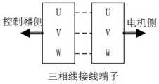
图1为本发明实施例的控制器、旋转变压器、三相线以及电机之间的连接关系示意图;1 is a schematic diagram of the connection relationship between a controller, a resolver, a three-phase line and a motor according to an embodiment of the present invention;
图2为本发明实施例的三相线与控制器侧和电机侧的接线端子的正确的接线方式示意图;2 is a schematic diagram of the correct wiring mode of the three-phase line and the wiring terminals on the controller side and the motor side according to an embodiment of the present invention;
图3为本发明实施例的旋转变压器与控制器侧和电机侧的接线端子的正确的接线方式示意图;3 is a schematic diagram of the correct wiring mode of the resolver and the connection terminals on the controller side and the motor side according to the embodiment of the present invention;
图4为本发明实施例的电机转子的初始位置和接线方式的确定方法的流程图;4 is a flowchart of a method for determining an initial position and a wiring mode of a motor rotor according to an embodiment of the present invention;
图5为本发明实施例的接线方式已知计算初始位置的方法的流程示意图;5 is a schematic flowchart of a method for calculating an initial position with a known wiring method according to an embodiment of the present invention;
图6为本发明实施例的计算初始位置的具体流程示意图。FIG. 6 is a schematic diagram of a specific flow of calculating an initial position according to an embodiment of the present invention.
具体实施方式Detailed ways
为使本发明的目的、技术方案和优点更加清楚明白,以下结合具体实施例,并参照附图,对本发明进一步详细说明。In order to make the objectives, technical solutions and advantages of the present invention clearer, the present invention will be further described in detail below with reference to specific embodiments and accompanying drawings.
需要说明的是,除非另外定义,本发明实施例使用的技术术语或者科学术语应当为本公开所属领域内具有一般技能的人士所理解的通常意义。本公开中使用的“第一”、“第二”以及类似的词语并不表示任何顺序、数量或者重要性,而只是用来区分不同的组成部分。“包括”或者“包含”等类似的词语意指出现该词前面的元件或者物件涵盖出现在该词后面列举的元件或者物件及其等同,而不排除其他元件或者物件。“连接”或者“相连”等类似的词语并非限定于物理的或者机械的连接,而是可以包括电性的连接,不管是直接的还是间接的。“上”、“下”、“左”、“右”等仅用于表示相对位置关系,当被描述对象的绝对位置改变后,则该相对位置关系也可能相应地改变。It should be noted that, unless otherwise defined, the technical or scientific terms used in the embodiments of the present invention shall have the usual meanings understood by those with ordinary skill in the art to which the present disclosure belongs. As used in this disclosure, "first," "second," and similar terms do not denote any order, quantity, or importance, but are merely used to distinguish the various components. "Comprises" or "comprising" and similar words mean that the elements or things appearing before the word encompass the elements or things recited after the word and their equivalents, but do not exclude other elements or things. Words like "connected" or "connected" are not limited to physical or mechanical connections, but may include electrical connections, whether direct or indirect. "Up", "Down", "Left", "Right", etc. are only used to represent the relative positional relationship, and when the absolute position of the described object changes, the relative positional relationship may also change accordingly.
如图1所示,为控制器、旋转变压器、三相线以及电机之间的连接关系示意图。在控制器侧和电机侧分别具有三相端子,即U相、V相和W相。其中,当三相线分别将控制器侧的U相与电机侧的U相、控制器侧的V相与电机侧的V相、控制器侧的W相与电机侧的W相对应连接时,为三相线与控制器侧和电机侧的接线端子的正确的接线方式,如图2所示。As shown in Figure 1, it is a schematic diagram of the connection relationship between the controller, the resolver, the three-phase line and the motor. There are three-phase terminals on the controller side and the motor side, namely U-phase, V-phase and W-phase. Among them, when the three-phase lines connect the U-phase on the controller side and the U-phase on the motor side, the V-phase on the controller side and the V-phase on the motor side, and the W-phase on the controller side and the W-phase on the motor side correspondingly, It is the correct wiring method of the three-phase line and the terminals on the controller side and the motor side, as shown in Figure 2.
旋转变压器有3个绕组,分别为激励绕组、正弦绕组和余弦绕组。3个绕组分别引出到6个接线端子:exc+(激励正),exc-(激励负)、sin+(正弦正)、sin-(正弦负)、cos+(余弦正)、cos-(余弦负)。正确的接线方式如图3所示,即旋转变压器的激励绕组分别将电机侧的激励正与控制器侧的激励正、电机侧的激励负与控制器侧的激励负对应连接;旋转变压器的正弦绕组分别将电机侧的正弦正与控制器侧的正弦正、电机侧的正弦负与控制器侧的正弦负对应连接;旋转变压器的余弦绕组分别将电机侧的余弦正与控制器侧的余弦正、电机侧的余弦负与控制器侧的余弦负对应连接。The resolver has 3 windings, namely excitation winding, sine winding and cosine winding. The 3 windings are respectively led out to 6 terminals: exc+ (excitation positive), exc- (excitation negative), sin+ (sine positive), sin- (sine negative), cos+ (cosine positive), cos- (cosine negative). The correct wiring method is shown in Figure 3, that is, the excitation winding of the resolver connects the excitation positive of the motor side with the excitation positive of the controller side, and the excitation negative of the motor side and the excitation negative of the controller side respectively; The windings respectively connect the sine of the motor side to the sine of the controller side, and the sine of the motor side to the sine of the controller side correspondingly; the cosine windings of the resolver respectively connect the cosine of the motor side to the cosine of the controller side. , The negative cosine on the motor side is correspondingly connected with the negative cosine on the controller side.
电机在出厂时,即产出后未使用之前,电机转子具有出厂位置,包括出厂电角度和出厂电角度相位两个数据。出厂电角度即电机转子相对于旋转变压器的电角度差值。将电机逆时针旋转称为电机正转,顺时针旋转称为电机反转。电机正转时旋转变压器相对位置递增或者电机反转时旋转变压器相对位置递减称为旋转变压器同相,电机正转时旋转变压器相对位置递减或者电机反转时旋转变压器相对位置递增称为旋转变压器反相。When the motor leaves the factory, that is, before it is not used after production, the rotor of the motor has the factory position, including the factory electrical angle and the factory electrical angle phase. The factory electrical angle is the electrical angle difference between the motor rotor and the resolver. Rotating the motor counterclockwise is called motor forward rotation, and clockwise rotation is called motor reverse rotation. The relative position of the resolver increases when the motor is rotating forward or the relative position of the resolver decreases when the motor is reversed, which is called resolver in-phase, and when the motor is rotating forward, the relative position of the resolver decreases or when the motor is reversed. .
例如,电机转子的电角度为0如,旋转变压器的电角度为50转,当电机转子旋转至1当,如果旋转变压器旋转至51果,那么旋转变压器相对电机转子为同相;而如果旋转变压器旋转至49么,那么旋转变压器相对电机转子为反相。本申请中定义同相用数字0表示,反相用数字1表示。For example, the electrical angle of the motor rotor is 0. For example, the electrical angle of the resolver is 50 turns. When the motor rotor rotates to 1°, if the resolver rotates to 51°, then the resolver is in phase with the motor rotor; and if the resolver rotates To 49, then the resolver is out of phase with respect to the motor rotor. It is defined in this application that the in-phase is represented by the number 0, and the reverse phase is represented by the number 1.
发明人在长期的电机调试的工作中发现,在实际的调试现场,三相线束与旋转变压器的绕组,均有可能接线错误,使电机侧与控制器侧的各个接线端子无法正确对应,出现同一种类型的接线错误。当这种类型的接线错误发生时,控制器仍能正常检测旋转变压器相对位置,但是由于接线错误,电机的转子往往会脱离出厂位置,导致控制器无法准确计算电机转子的绝对位置,无法正常驱动电机,对于线束标号缺失、既定线束无法更改、拆卸困难等线束不方便重接的情况,确定接线方式和初始位置非常困难,也无法记录真实的接线方式,对于电机的调试和安全运行造成了极大的不便。In the long-term motor debugging work, the inventor found that in the actual debugging site, the three-phase wiring harness and the windings of the resolver may be wired incorrectly, so that the wiring terminals on the motor side and the controller side cannot be correctly corresponded, and the same appearance occurs. types of wiring errors. When this type of wiring error occurs, the controller can still detect the relative position of the resolver normally, but due to the wiring error, the rotor of the motor is often out of the factory position, resulting in the controller unable to accurately calculate the absolute position of the motor rotor and unable to drive normally. For the motor, it is very difficult to determine the wiring method and initial position for the situation that the wiring harness is inconvenient to reconnect, such as the missing wiring harness label, the fixed wiring harness cannot be changed, and the disassembly is difficult. Big inconvenience.
发明人提出一种能够同时确定电机转子的初始位置和接线方式的方法。该方法根据出厂电位角相位为同相或反相时,按照可能的错误接线方式所对应的初始电位角相位差值和初始电位角差值,依据已知的接线方式查找初始电位角和初始电位角相位,或者依据已知的初始电位角和初始电位角相位查找接线方式,或者直接查找可能的初始电位角和初始电位角相位。The inventor proposes a method that can simultaneously determine the initial position and wiring mode of the motor rotor. This method searches for the initial potential angle and the initial potential angle according to the known wiring method according to the initial potential angle phase difference and the initial potential angle difference corresponding to the possible wrong wiring method when the phase of the factory potential angle is in-phase or opposite. Phase, or search the wiring mode according to the known initial potential angle and initial potential angle phase, or directly search for possible initial potential angle and initial potential angle phase.
并分析接线方式和初始位置,分析接线方式和初始位置是否已知,并根据接线方式和初始位置的已知情况,查找对应的初始电位角相位差值和初始电位角差值,确定接线方式和初始位置。And analyze the wiring mode and initial position, analyze whether the wiring mode and initial position are known, and according to the known situation of the wiring mode and initial position, find the corresponding initial potential angle phase difference and initial potential angle difference, determine the wiring mode and initial position.
请参阅图4,为本发明实施例提供的一种电机转子的初始位置和接线方式的确定方法,应用于接线错误的有旋转变压器的三相电机,所述初始位置包括初始电位角和初始电位角相位,所述确定方法包括:Please refer to FIG. 4 , which is a method for determining the initial position and wiring mode of a motor rotor provided by an embodiment of the present invention, which is applied to a three-phase motor with a resolver with wrong wiring, and the initial position includes an initial potential angle and an initial potential Angular phase, the determination method includes:
S100,提供多种错误接线类型的接线方式,代表旋转变压器和/或三相线束接线错误;S100, which provides a variety of wiring methods for incorrect wiring types, representing the wrong wiring of the resolver and/or the three-phase wiring harness;
S200,分别提供出厂电位角相位为同相和反相时,不同的接线方式对应的初始电位角相位差值和初始电位角差值;S200, respectively provide the initial potential angle phase difference value and the initial potential angle difference value corresponding to different wiring modes when the factory potential angle phase is in-phase and opposite-phase;
S300,当初始位置已知,接线方式未知时,计算初始电位角相位差值和初始电位角差值,并根据出厂电位角相位,查找对应的接线方式;S300, when the initial position is known and the wiring mode is unknown, calculate the initial potential angle phase difference and the initial potential angle difference, and find the corresponding wiring mode according to the factory potential angle phase;
S400,当接线方式已知,初始位置未知时,根据出厂电位角相位,查找对应的初始电位角相位差值和初始电位角差值,并计算初始电位角相位和初始电位角;S400, when the wiring method is known and the initial position is unknown, according to the factory potential angle phase, find the corresponding initial potential angle phase difference and initial potential angle difference, and calculate the initial potential angle phase and initial potential angle;
S500,当接线方式和初始位置均未知时,依次根据不同接线方式时的初始电位角相位差值和初始电位角差值计算初始电位角相位和初始电位角,试运行电机,判断电机的运行情况,记录电机运行情况良好时对应的初始电位角相位和初始电位角,并查找对应的接线方式。S500, when the wiring mode and the initial position are unknown, calculate the initial potential angle phase and initial potential angle according to the initial potential angle phase difference and the initial potential angle difference in different wiring modes, test the motor, and judge the operation of the motor , record the corresponding initial potential angle phase and initial potential angle when the motor is running well, and find the corresponding wiring method.
步骤S100中,所述多种错误接线类型包括第一错误接线类型、第二错误接线类型和第三错误接线类型。其中,第一错误接线类型为仅旋转变压器接线错误,三相线束接线正确。第二错误接线类型为仅三相线束接线旋错误,转变压器接线正确;第三错误接线类型为旋转变压器和三相线束均接线错误。In step S100, the multiple types of incorrect wiring include a first type of incorrect wiring, a second type of incorrect wiring, and a third type of incorrect wiring. Among them, the first wrong wiring type is that only the resolver is connected incorrectly, and the three-phase wiring harness is correctly connected. The second wrong wiring type is that only the three-phase wiring harness is wired incorrectly, and the transformer wiring is correct; the third wrong wiring type is that both the resolver and the three-phase wiring harness are wired incorrectly.
第一错误接线类型规定电机侧激励端子只能接到控制器侧的激励端子,电机侧的正弦端子不能分开接到控制器侧的正弦和余弦端子,电机侧的余弦端子不能分开接到控制器侧的正弦和余弦端子。按照上述规则,旋转变压器接线错误时,第一错误接线类型存在五种子类型,15种的接线方式:第一子类型、仅对调exc+/-,如表1中编号9所示;第二子类型、仅对调sin+/-,如表1中编号2所示;第三子类型,仅对调cos+/-,如表1中编号10所示;第四子类型,仅对调sin/cos,如表1中编号6所示;第五子类型、同时出现第一子类型、第二子类型、第三子类型和第四子类型中的多重对调,如表1中编号1、3、4、5、7、8、11、12、13、14、15所示。表1中编号0所示为正确的接线方式。The first wrong wiring type stipulates that the excitation terminal on the motor side can only be connected to the excitation terminal on the controller side, the sine terminal on the motor side cannot be separately connected to the sine and cosine terminals on the controller side, and the cosine terminal on the motor side cannot be separately connected to the controller. sine and cosine terminals on the side. According to the above rules, when the resolver is wrongly wired, there are five sub-types and 15 wiring methods for the first wrong wiring type: the first sub-type, only swap exc+/-, as shown in No. 9 in Table 1; the second sub-type , only swap sin+/-, as shown in No. 2 in Table 1; for the third subtype, only swap cos+/-, as shown in No. 10 in Table 1; for the fourth subtype, only swap sin/cos, as shown in Table 1 Number 6 in the fifth subtype, multiple swaps in the first subtype, the second subtype, the third subtype and the fourth subtype appear at the same time, as shown in Table 1, numbered 1, 3, 4, 5, 7, 8, 11, 12, 13, 14, 15. No. 0 in Table 1 shows the correct wiring method.
第二错误接线类型中,即仅三相线接线错误时,具体的接线方式有5种,见表2。表2中,编号a对应的接线方式为正确的接线方式,编号b~f为5种错误的接线方式。In the second type of wrong wiring, that is, when only the three-phase line is wired incorrectly, there are five specific wiring methods, see Table 2. In Table 2, the wiring method corresponding to the number a is the correct wiring method, and the numbers b to f are five wrong wiring methods.
第三错误接线类型中,即三相线束和旋转变压器同时接线错误时,三相线束和接线端子与旋转变压器线束和接线端子区别较大,实际中几乎不可能发生三相线束与旋转变压器线对调的情况,因此将上述表1中的6种三相线束接线方式和表2中的16种旋转变压器接线方式组合,一共能得到6*16=96种不同的三相与旋转变压器接线方式,其中1种为正确的接线方式,剩余的95种均为错误的接线方式。In the third type of wrong wiring, that is, when the three-phase wiring harness and the resolver are wired incorrectly at the same time, the three-phase wiring harness and wiring terminals are quite different from the resolver wiring harness and wiring terminals, and it is almost impossible to swap the three-phase wiring harness and resolver wiring in practice. Therefore, combining the 6 three-phase harness wiring methods in Table 1 and the 16 resolver wiring methods in Table 2, a total of 6*16=96 different three-phase and resolver wiring methods can be obtained, of which 1 is the correct wiring method, and the remaining 95 are the wrong wiring methods.
表1旋转变压器接线方式Table 1 Resolver wiring method

表2三相线束接线方式Table 2 Three-phase wiring harness wiring method

步骤S200中,出厂电角度相位P0包括旋转变压器同相和旋转变压器反相,定义旋转变压器同相用数值0表示,旋转变压器同相用数值1表示。针对不同的出厂电角度相位,同一种接线方式对应的初始电角度相位差值和初始电位角差值可能相同,也可能不相同,需根据具体的接线方式确定。In step S200, the factory electrical angle phase P0 includes the resolver in-phase and the resolver inversion, and it is defined that the resolver in-phase is represented by a value of 0, and the resolver in-phase is represented by a value of 1. For different electrical angle phases from the factory, the initial electrical angle phase difference and the initial potential angle difference corresponding to the same wiring method may be the same or different, which need to be determined according to the specific wiring method.
具体地,所述不同的接线方式对应的初始电位角相位差值通过ΔP=mod(ΔPRD+ΔPP,2)计算,其中,ΔP为初始电位角相位差值,mod为求余函数,ΔPRD为仅旋转变压器接线错误时的初始电位角相位差值,ΔPP为仅三相线束接线错误时的初始电位角相位差值,mod(,2)为对2取余。Specifically, the initial potential angle phase difference value corresponding to the different wiring modes is calculated by ΔP=mod(ΔPRD +ΔPP ,2), where ΔP is the initial potential angle phase difference value, mod is the remainder function, ΔPRD is the initial potential angle phase difference value when only the resolver is wired incorrectly, ΔPP is the initial potential angle phase difference value when only the three-phase wiring harness is incorrectly wired, mod(,2) is the remainder of 2.
表3不同旋转变压器线对调方式下的


进一步地,ΔPRD通过


ΔPP的取值为0或1,当ΔPP取值为0时,表示电机侧的U相端子/V相端子对接至控制器侧的U相端子/V相端子或控制器侧的V相端子/W相端子或控制器侧的W相端子/U相端子;当ΔPP取值为1时,表示电机侧的U相端子/V相端子对接至控制器侧的U相端子/W相端子或控制器侧的V相端子/U相端子或控制器侧的W相端子/V相端子。The value of ΔPP is 0 or 1. When the value of ΔPP is 0, it means that the U-phase terminal/V-phase terminal on the motor side is connected to the U-phase terminal/V-phase terminal on the controller side or the V-phase terminal on the controller side. Terminal/W-phase terminal or W-phase terminal/U-phase terminal on the controller side; when the value of ΔPP is 1, it means that the U-phase terminal/V-phase terminal on the motor side is connected to the U-phase terminal/W-phase terminal on the controller side Terminals or V-phase terminal/U-phase terminal on the controller side or W-phase terminal/V-phase terminal on the controller side.
表4不同旋转变压器接线的初始电位角相位差值和初始电位角差值Table 4 Initial potential angle phase difference and initial potential angle difference of different resolver connections

ΔPP可通过
具体地,所述不同的接线方式对应的初始电位角差值通过Δθ=mod(ΔθRD+ΔθPRD,360)计算,其中,Δθ为初始电位角差值,ΔθRD为仅旋转变压器接线错误时的初始电位角差值,ΔθPRD通过
ΔθPRD的含义可以理解为,假设三相线束接线正确,按照仅出现旋转变压器接线错误的计算方法得新初始电位角相位P1RD,然后以P1RD作为出厂初始电位角相位,根据公式
表5不同三相线束接线的初始电位角相位差值和初始电位角差值Table 5 Initial potential angle phase difference and initial potential angle difference of different three-phase wiring harnesses

进一步地,ΔθRD通过


P1RD通过P1RD=mod(P0+ΔPRD,2)计算,其中,ΔPRD为仅旋转变压器接线错误时的初始电位角相位差值,通过


经过计算,所述不同的接线方式对应的初始电位角相位差值ΔP的取值仅有2个,0和1,设为ΔPlist;所述不同的接线方式对应的初始电位角差值Δθ的取值仅有12个,{0,30,60,90,120,150,180,210,240,270,300,330},设为Δθlist。因此,96种接线方式得到的ΔP和Δθ只有2*12=24种组合方式,设为ΔPΔθlist(ΔP,Δθ),ΔP∈ΔPlist,Δθ∈Δθlist。也就是说,ΔPΔθlist的每一个值对应4种不同的三相和旋转变压器接线方式,且这4种方式是由2种三相线束接线和2种旋转变压器接线组合成的。也就是说,ΔP和Δθ确定的情况下,能得到4种可能的接线方式,进一步,若此时还能确定三相或者旋转变压器接线方式,那么能分别得到2种可能的旋转变压器或者2种可能的三相线束接线方式。After calculation, the initial potential angle phase difference value ΔP corresponding to the different wiring methods has only 2 values, 0 and 1, which are set as ΔPlist ; the initial potential angle difference value Δθ corresponding to the different wiring methods is There are only 12 values, {0, 30, 60, 90, 120, 150, 180, 210, 240, 270, 300, 330}, set as Δθlist . Therefore, there are only 2*12=24 combinations of ΔP and Δθ obtained from 96 wiring methods, which are set as ΔPΔθlist (ΔP, Δθ), ΔP∈ΔPlist , Δθ∈Δθlist . That is to say, each value of ΔPΔθlist corresponds to 4 different three-phase and resolver wiring methods, and these 4 methods are composed of 2 types of three-phase wiring harness wiring and 2 types of resolver wiring. That is to say, when ΔP and Δθ are determined, 4 possible connection methods can be obtained. Further, if the three-phase or resolver connection method can be determined at this time, then 2 possible resolver or 2 possible connection methods can be obtained respectively. Possible three-phase wiring harnesses.
所提供的不同的接线方式对应的初始电位角相位差值和初始电位角差值可以以表格的形式呈现。以表格呈现时,出厂电角度相位P0为0时,对应一个表,如表6;出厂电角度相位P0为1时,对应另外一个表,如表7。表6和表7中,“-”对之前的数据为Δθ,“-”据之后的数据为ΔP。The initial potential angle phase difference and the initial potential angle difference corresponding to the different wiring modes provided can be presented in the form of a table. When presented in a table, when the factory electrical angle phase P0 is 0, it corresponds to one table, as shown in Table 6; when the factory electrical angle phase P0 is 1, it corresponds to another table, as shown in Table 7. In Tables 6 and 7, "-" means Δθ for the data before "-", and ΔP for the data after "-".
表6出厂电角度相位为0时的初始电位角差值和初始电位角相位差值Table 6 Initial potential angle difference and initial potential angle phase difference when the factory electrical angle phase is 0

表格的构建过程具体可以包括:The construction process of the table can specifically include:
根据初始电位角相位差值计算公式,分别计算不同接线方式对应的初始电位角相位差值,得到出厂电位角相位分别为同相和反相时,接线方式与电位角相位差值的第一对应关系表和第二对应关系表;According to the calculation formula of the initial potential angle phase difference value, calculate the initial potential angle phase difference value corresponding to different wiring modes, and obtain the first correspondence between the wiring mode and the potential angle phase difference value when the factory potential angle phase is in-phase and anti-phase respectively. table and the second correspondence table;
根据所述初始电位角差值计算公式,分别计算不同组合接线方式对应的初始电位角差值,得到不同出厂电位角相位分别为同相和反相时,接线方式与电位角差值的第三对应关系表和第四对应关系表;According to the calculation formula of the initial potential angle difference, calculate the initial potential angle difference corresponding to different combined wiring modes, and obtain the third correspondence between the wiring mode and the potential angle difference when the different factory potential angle phases are in-phase and anti-phase respectively. The relationship table and the fourth corresponding relationship table;
将所述第一对应关系表与所述第三对应关系表组合即可得到表6;将第二对应关系表和第四对应关系表组合即可得到表7。Table 6 can be obtained by combining the first corresponding relationship table and the third corresponding relationship table; Table 7 can be obtained by combining the second corresponding relationship table and the fourth corresponding relationship table.
步骤S300中,初始位置可通过初始电位角标定或者带有初始电位角辨识功能的控制器自学习等方式获得。In step S300, the initial position may be obtained by means of initial potential angle calibration or self-learning of the controller with the initial potential angle identification function.
表7出厂电角度相位为1时的初始电位角差值和初始电位角相位差值Table 7 Initial potential angle difference and initial potential angle phase difference when the factory electrical angle phase is 1

所述计算初始电位角相位差值,包括通过公式P1=mod(P0+ΔP,2)(1)计算,其中,P1为初始电位角相位,P0为出厂初始电位角相位,ΔP为初始电位角相位差值。The calculation of the initial potential angle phase difference includes calculation by formula P1 =mod(P0 +ΔP,2)(1), where P1 is the initial potential angle phase, P0 is the factory initial potential angle phase, ΔP is the initial potential angle phase difference value.
所述计算初始电位角差值,包括通过公式θ1=mod(θ0+Δθ,360)(2)计算,其中,θ1为初始电位角,θ0为出厂初始电位角,Δθ为初始电位角差值。The calculation of the initial potential angle difference includes calculation by the formula θ1 =mod(θ0 +Δθ, 360) (2), where θ1 is the initial potential angle, θ0 is the factory initial potential angle, and Δθ is the initial potential Angle difference.
进一步地,当计算所得初始电位角差值的值与所提供的初始电位角差值均不相符时,对计算所得初始电位角差值的值进行舍入处理,选取Δθlist最接近的数值,并按照该最接近的数值查找对应的接线方式。Further, when the value of the calculated initial potential angle difference does not match the provided initial potential angle difference, the calculated value of the initial potential angle difference is rounded, and the closest value of the Δθlist is selected, And find the corresponding wiring method according to the closest value.
在一个具体的实施例中,出厂初始电位角θ0为231,出厂初始电位角相位P0为0,且根据重新标定或者控制器自学习等方式得到了接线错误情况下的初始电位角θ1为82,初始电位角相位P1为1。In a specific embodiment, the factory initial potential angle θ0 is 231, the factory initial potential angle phase P0 is 0, and the initial potential angle θ1 in the case of a wiring error is obtained according to re-calibration or controller self-learning. is 82, and the initial potential angle phase P1 is1 .
根据公式(1)和公式(2)计算得到ΔP=1和Δθ=211。由于标定或者控制器自学习等方式得到初始电位角存在一定的误差(一般为±2左右),因此需要对Δθ舍入处理到最接近的Δθlist中的某个值。此处,Δθ为211最接近210,因此,舍入处理使得Δθ=210。出厂初始电位角相位P0为0,所以从表6中根据ΔP=1和Δθ=210,查到此时可能的接线方式为d4、d5、e6、e7共4种方式。According to formula (1) and formula (2), ΔP=1 and Δθ=211 are obtained. Since the initial potential angle obtained by calibration or controller self-learning has a certain error (generally about ±2), it is necessary to round Δθ to a certain value in the closest Δθlist . Here, Δθ is 211 closest to 210, so the rounding process makes Δθ=210. The factory initial potential angle phase P0 is 0, so from Table 6, according to ΔP=1 and Δθ=210, it is found that the possible wiring methods at this time are d4, d5, e6, and e7 in total 4 ways.
步骤S400中,所述计算初始电位角相位,包括通过公式P1=mod(P0+ΔP,2)(1)计算,其中,P1为初始电位角相位,P0为出厂初始电位角相位,ΔP为初始电位角相位差值。In step S400, the calculation of the initial potential angular phase includes calculation by formula P1 =mod(P0 +ΔP,2)(1), wherein P1 is the initial potential angular phase, and P0 is the factory initial potential angular phase , ΔP is the initial potential angle phase difference.
所述计算初始电位角,包括通过公式θ1=mod(θ0+Δθ,360)(2)计算,其中,θ1为初始电位角,θ0为出厂初始电位角,Δθ为初始电位角差值。The calculation of the initial potential angle includes calculation by the formula θ1 =mod(θ0 +Δθ, 360) (2), where θ1 is the initial potential angle, θ0 is the factory initial potential angle, and Δθ is the initial potential angle difference value.
在一个具体的实施例中,当接线方式已知,如表8所示,出厂初始电位角θ0为321,出厂初始电位角相位P0为1。则从表7中查ΔP和Δθ,查找到表8中所示的接线方式对应为表7中编号为7的旋转变压器接线方式,以及编号为e的三相线束接线方式。因此,查e7位置的ΔP和Δθ,得到ΔP为1,Δθ为210。再根据公式(1)和公式(2)计算得到新初始电位角相位P1=mod(1+1,2)=0,新初始电位角θ1=mod(321+210,360)=171。In a specific embodiment, when the wiring method is known, as shown in Table 8, the factory initial potential angle θ0 is 321, and the factory initial potential angle phase P0 is 1. Then check ΔP and Δθ from Table 7, and find that the wiring method shown in Table 8 corresponds to the resolver wiring method numbered 7 in Table 7, and the three-phase wiring harness wiring method numbered e. Therefore, looking at the ΔP and Δθ at the e7 position, ΔP is 1 and Δθ is 210. According to formula (1) and formula (2), the new initial potential angle phase P1 =mod(1+1,2)=0, and the new initial potential angle θ1 =mod(321+210,360)=171 are obtained.
表8三相和旋转变压器接线错误示例Table 8 Examples of three-phase and resolver wiring errors
步骤S500中,电机运行情况可以根据如能否运行、电流参数、指令响应等来判断,例如反馈电流波动大小、转速转矩指令跟踪情况、0转矩指令的实际输出转矩等多种方式判断是否运行良好。电机具体的运行,是本领域悉知的技术,此处不再赘述。In step S500, the operation of the motor can be judged according to whether it can run, current parameters, command response, etc., such as feedback current fluctuations, speed and torque command tracking, and the actual output torque of 0 torque commands. Is it working well. The specific operation of the motor is a well-known technology in the art, and will not be repeated here.
在初始位置未知且无法标定或者自学习的极端情况下,允许电机试运行,通过尝试一些可能的初始位置值,根据电机的实际运行情况,不断调整电位角差值,会使得最终尝试的初始位置不断接近实际初始位置。具体调整时,若电机的运行情况越恶化,可判断当前尝试的初始位置与实际的初始位置相差越大,例如初始电位角差值调大运行更恶化,则对数值进行调小处理,直至运行良好。In extreme cases where the initial position is unknown and cannot be calibrated or self-learned, the motor is allowed to run for a trial run. By trying some possible initial position values, and according to the actual operation of the motor, continuously adjusting the potential angle difference will make the final attempted initial position. keep approaching the actual initial position. During the specific adjustment, if the running condition of the motor deteriorates, it can be judged that the difference between the initial position of the current attempt and the actual initial position is larger. good.
在一个具体的实施例中,假设出厂初始电位角θ0为231,出厂初始电位角相位P0为0,那么θ1可能的结果有12种,即mod(231+Δθlist,360),P1的结果有2种,0和1。因此可分别设定P1为0和1,θ1按mod(231+Δθlist,360)逐一取值试运行电机,比如第20次尝试发现电机运行良好,此时ΔP为1,Δθ为210,那么可认为新初始电位角相位为1,新初始电位角为81,按已知新初始位置反查接线方式查表方法能得到可能的接线方式为d4、d5、e6、e7。In a specific embodiment, assuming that the factory initial potential angle θ0 is 231, and the factory initial potential angle phase P0 is 0, then there are 12 possible results of θ1 , namely mod(231+Δθlist , 360), P There are 2 kinds of results of1 , 0 and 1. Therefore, P1 can be set to 0 and 1, respectively, and θ1 can be set as mod(231+Δθlist ,360) to test the motor one by one. For example, the 20th attempt found that the motor is running well. At this time, ΔP is 1 and Δθ is 210. , then it can be considered that the phase of the new initial potential angle is 1, and the new initial potential angle is 81. According to the known new initial position, the possible wiring methods are d4, d5, e6, and e7.
若经过24次初始位置尝试,电机仍不能正常运行,且能确定控制器与电机功能完好,线束接触良好,那么此时可作为一个参考依据,判定旋转变压器发生了机械位置滑移或者接线方式不属于96种接线方式中的任何一种。If after 24 initial position attempts, the motor still cannot run normally, and it can be determined that the controller and the motor function in good condition, and the wiring harness is in good contact, then it can be used as a reference to determine that the resolver has undergone mechanical position slip or the wiring method is incorrect. Belongs to any of the 96 wiring methods.
本发明实施例提供的电机转子的初始位置和接线方式的确定方法,能够得到电机转子的初始位置和接线方式,提高调试现场的调试效率,同时还能排查接线错误。对于既定线束无法更改、拆卸困难等原因造成线束不方便重接的调试现场中已知错误接线方式的情况下,按照本发明提供的方法能够快速查找初始电位角相位差值和初始电位角差值,快速计算新位置,则不需要现场初始电位角标定或者初始电位角自学习,能提高调试效率;对于调试现场出现线束标号缺失造成无法重接线束的情况下,根据初始电位角标定或者初始电位角自学习得到的新位置,按照本发明提供的方法,能够快速反查出可能的错误接线方式,便于接线错误排查和记录;对于调试现场出现线束标号缺失,且初始位置未知也无法标定或者自学习的极端情况下,按照本申请提供的方法最多尝试24次能得到新位置及可能的错误接线方式,既能提高调试效率,也便于接线故障排查。The method for determining the initial position and wiring mode of the motor rotor provided by the embodiment of the present invention can obtain the initial position and wiring mode of the motor rotor, improve the debugging efficiency on the debugging site, and at the same time, check the wiring errors. In the case of known wrong wiring methods in the debugging site where the wiring harness cannot be changed, the disassembly is difficult, etc., the wiring harness is inconvenient to reconnect, the method provided by the present invention can quickly find the initial potential angle phase difference and the initial potential angle difference. , to quickly calculate the new position, it does not need on-site initial potential angle calibration or initial potential angle self-learning, which can improve the debugging efficiency; for the case where the wiring harness cannot be re-wired due to the lack of wiring harness labels at the debugging site, the initial potential angle calibration or initial potential The new position obtained by angle self-learning, according to the method provided by the present invention, the possible wrong wiring method can be quickly detected, which is convenient for the investigation and recording of wiring errors; when the wiring harness label is missing at the debugging site, and the initial position is unknown, it cannot be calibrated or automatically In the extreme case of learning, a new position and possible wrong wiring method can be obtained by trying the method provided in this application for a maximum of 24 times, which can not only improve the debugging efficiency, but also facilitate the wiring troubleshooting.
本发明实施例还提供另一种实施例,用于当接线方式已知,而初始位置未知时,通过公式计算确定该接线方式对应的初始位置。The embodiment of the present invention also provides another embodiment for determining the initial position corresponding to the connection mode through formula calculation when the connection mode is known but the initial position is unknown.
请参阅图5,包括:See Figure 5, including:
S600,获取接线方式,分析所述接线方式对应的错误接线类型;S600, acquiring the wiring mode, and analyzing the wrong wiring type corresponding to the wiring mode;
S700,根据所述错误接线类型,计算电机的实际初始电角度和实际初始电角度相位。S700, according to the wrong wiring type, calculate the actual initial electrical angle and the actual initial electrical angle phase of the motor.
步骤S600中,错误接线类型包括第一错误接线类型、第二错误接线类型和第三错误接线类型。其中,第一错误接线类型为仅旋转变压器接线错误,三相线束接线正确。第二错误接线类型为仅三相线束接线旋错误,转变压器接线正确;第三错误接线类型为旋转变压器和三相线束均接线错误。In step S600, the wrong wiring types include a first wrong wiring type, a second wrong wiring type, and a third wrong wiring type. Among them, the first wrong wiring type is that only the resolver is connected incorrectly, and the three-phase wiring harness is correctly connected. The second wrong wiring type is that only the three-phase wiring harness is wired incorrectly, and the transformer wiring is correct; the third wrong wiring type is that both the resolver and the three-phase wiring harness are wired incorrectly.
具体地,每种错误接线类型的规则和具体的接线方式与前述实施例均相同,此处不再赘述。Specifically, the rules and specific wiring manners of each type of wrong wiring are the same as those in the foregoing embodiments, which will not be repeated here.
请参阅图6,步骤S700中,包括:Please refer to FIG. 6, step S700 includes:
S701,当所述错误接线类型为第一错误接线类型时,分别通过第一实际初始电位角计算公式和第一实际初始电位角相位计算公式来计算第一实际初始电位角和第一实际初始电位角相位;S701, when the wrong wiring type is the first wrong wiring type, calculate the first actual initial potential angle and the first actual initial potential by using the first actual initial potential angle calculation formula and the first actual initial potential angle phase calculation formula respectively angular phase;
S702,当所述错误接线类型为第二错误接线类型时,分别通过第二实际初始电位角计算公式和第二实际初始电位角相位计算公式来计算第二实际初始电位角和第二实际初始电位角相位;S702, when the wrong wiring type is the second wrong wiring type, calculate the second actual initial potential angle and the second actual initial potential by using the second actual initial potential angle calculation formula and the second actual initial potential angle phase calculation formula respectively angular phase;
S703,当所述错误接线类型为第三错误接线类型时,分别通过第三实际初始电位角计算公式和第三实际初始电位角相位计算公式来计算第三实际初始电位角和第三实际初始电位角相位。S703, when the wrong wiring type is the third wrong wiring type, calculate the third actual initial potential angle and the third actual initial potential respectively by using the third actual initial potential angle calculation formula and the third actual initial potential angle phase calculation formula angular phase.
步骤S701中,第一实际初始电位角相位计算公式如式(5)所示,P1RD=mod(P0+ΔPRD,2)(5),其中,P1RD为仅旋转变压器接线错误时的实际初始电角度相位,mod为求余函数,P0为出厂电角度相位,ΔPRD为仅旋转变压器接线错误时的初始电位角相位差值。In step S701, the first actual initial potential angle phase calculation formula is shown in formula (5), P1RD =mod(P0 +ΔPRD ,2)(5), where P1RD is only when the connection of the resolver is wrong. The actual initial electrical angle phase, mod is the remainder function, P0 is the factory electrical angle phase, and ΔPRD is the initial potential angle phase difference when only the resolver is wired incorrectly.
进一步地,ΔPRD按照公式(3)计算:


将第一子类型、第二子类型、第三子类型和第四子类型分别用数字1、2、3和4表示,则该式(3)中,字母n的取值为1、2、3、4。例如,表1中编号为6的旋转变压器接线方式,即第四子类型,仅对调sin/cos的接线方式,

第一实际初始电位角计算公式如式(6)所示,θ1RD=mod(θ0+ΔθRD,360)(6),其中,θ1RD为仅旋转变压器接线错误时的新初始电位角,θ0为出厂电角度,ΔθRD为仅旋转变压器接线错误时的初始电位角差值。The first actual initial potential angle calculation formula is shown in formula (6), θ1RD =mod(θ0 +ΔθRD ,360)(6), where θ1RD is the new initial potential angle when only the resolver is wired incorrectly, θ0 is the factory electrical angle, and ΔθRD is the initial potential angle difference when only the resolver is wired incorrectly.
进一步地,ΔθRD按照公式(4)计算:


将第一子类型、第二子类型、第三子类型和第四子类型分别用数字1、2、3和4表示,则该式(4)中,字母n的取值为1、2、3、4。例如,表1中编号为6的旋转变压器接线方式,即第四子类型,仅对调sin/cos的接线方式,
步骤S702中,第二实际初始电位角相位计算公式如式(9)所示,P1P=mod(P0+ΔPP,2)(9),其中,P1P为仅三相线束接线错误时的新初始电位角相位,mod为求余函数,P0为出厂电角度相位,ΔPP为仅三相线束接线错误时的初始电位角相位差值。In step S702, the calculation formula of the second actual initial potential angle phase is shown in formula (9), P1P =mod(P0 +ΔPP ,2)(9), where P1P is only when the three-phase wiring harness is wired incorrectly The new initial potential angle phase of , mod is the remainder function, P0 is the factory electrical angle phase, and ΔPP is the initial potential angle phase difference value when only the three-phase wiring harness is wired incorrectly.
进一步地,ΔPP按照公式(7)计算:Further, ΔPP is calculated according to formula (7):

第二实际初始电位角计算公式如式(10)所示,θ1P=mod(θ0+ΔθP,360)The second actual initial potential angle calculation formula is shown in formula (10), θ1P =mod(θ0 +ΔθP ,360)
(10),其中,θ1P为仅三相线束接线错误时的实际初始电位角,mod为求余函数,θ0为出厂电角度,ΔθP为仅三相线束接线错误时的初始电位角差值。(10), where θ1P is the actual initial potential angle when only the three-phase wiring harness is wired incorrectly, mod is the remainder function, θ0 is the factory electrical angle, and ΔθP is the initial potential angle difference when only the three-phase wiring harness is wired incorrectly value.
进一步地,ΔθP按照公式(8)计算:
步骤S703中,第三实际初始电位角相位计算公式如式(14)所示,P1PRD=mod(P0+ΔPRD+ΔPP,2)(14),其中,P1PRD为旋转变压器和三相线束均接线错误时的新初始电位角相位,mod为求余函数,P0为出厂电角度相位,ΔPRD为仅旋转变压器接线错误时的初始电位角相位差值,ΔPP为仅三相线束接线错误时的初始电位角相位差值。In step S703, the calculation formula of the third actual initial potential angle phase is shown in formula (14), P1PRD =mod(P0 +ΔPRD +ΔPP ,2) (14), where P1PRD is the resolver and the three The new initial potential angle phase when the phase wiring harnesses are all wired incorrectly, mod is the remainder function, P0 is the factory electrical angle phase, ΔPRD is the initial potential angle phase difference when only the resolver is wired incorrectly, ΔPP is only three-phase The initial potential angle phase difference value when the wiring harness is incorrectly wired.
第三实际初始电位角计算公式如式(15)所示,The calculation formula of the third actual initial potential angle is shown in formula (15),
θ1PRD=mod(θ0+ΔθRD+ΔθPRD,360)(15),其中,θ1PRD为旋转变压器和三相线束均接线错误时的新初始电位角,mod为求余函数,θ0为出厂电角度,ΔθRD为仅旋转变压器接线错误时的初始电位角差值,ΔθPRD为假设三相线束接线正确,按照仅出现旋转变压器接线错误的计算方法得新初始电位角相位P1RD,然后以P1RD作为出厂初始电位角相位,根据公式(8)计算所得。θ1PRD =mod(θ0 +ΔθRD +ΔθPRD ,360)(15), where θ1PRD is the new initial potential angle when both the resolver and the three-phase wiring harness are wired incorrectly, mod is the remainder function, and θ0 is Factory electrical angle, ΔθRD is the initial potential angle difference when only the resolver is wired incorrectly, ΔθPRD is the new initial potential angle phase P1RD , assuming that the three-phase wiring harness is correctly wired, according to the calculation method that only the resolver is wired incorrectly, and then Taking P1RD as the factory initial potential angle phase, it is calculated according to formula (8).
进一步地,ΔθPRD按照公式(13)计算:
应当说明的是,公式(14)也同时适用于仅旋转变压器接线错误和仅三相线束接线错误时,实际初始电位角相位的计算,例如当仅旋转变压器接线错误时,公式中ΔPP默认为0,即不存在;例如当仅三相线束接线错误时,公式中ΔPRD为0,即不存在。公式(15)也同时适用于仅旋转变压器接线错误和仅三相线束接线错误时,实际初始电位角的计算,例如当仅旋转变压器接线错误时,公式中ΔθPRD默认为0,即不存在;例如当仅三相线束接线错误时,公式中ΔθRD默认为0,即不存在,ΔθPRD实际上等于ΔθP。It should be noted that the formula (14) is also applicable to the calculation of the actual initial potential angle phase when only the resolver is wired incorrectly and only the three-phase wiring harness is incorrectly wired. For example, when only the resolver is wired incorrectly, ΔPP in the formula defaults to 0, that is, does not exist; for example, when only the three-phase wiring harness is wired incorrectly, ΔPRD in the formula is 0, that is, does not exist. Equation (15) is also applicable to the calculation of the actual initial potential angle when only the resolver is wired incorrectly and only the three-phase harness is wired incorrectly. For example, when only the resolver is wired incorrectly, ΔθPRD in the formula defaults to 0, that is, it does not exist; For example, when only the three-phase wiring harness is wired incorrectly, ΔθRD in the formula defaults to 0, that is, it does not exist, and ΔθPRD is actually equal to ΔθP .
本实施例通过分析已知的接线方式,并分析该接线方式对应的错误的接线类型,选择相应的公式,先计算初始电位角差值和初始电位角相位差值,再根据初始电位角差值和初始电位角相位差值计算得到初始电位角和初始电位角相位,即可得到初始位置。对于既定线束无法更改、拆卸困难等原因造成线束不方便重接的调试现场中已知错误接线方式的情况下,按照本发明提供的方法能够直接计算初始电位角相位差值和初始电位角差值,快速计算新位置,则不需要现场初始电位角标定或者初始电位角自学习,从而提高了调试效率。In this embodiment, by analyzing the known wiring method, and analyzing the wrong wiring type corresponding to the wiring method, select the corresponding formula, first calculate the initial potential angle difference and the initial potential angle phase difference, and then calculate the initial potential angle difference according to the initial potential angle difference. Calculate the initial potential angle and the initial potential angle phase by calculating the phase difference with the initial potential angle, and then the initial position can be obtained. In the case of a known wrong wiring method in the debugging site where the wiring harness cannot be changed, the disassembly is difficult, etc., and the wiring harness is inconvenient to reconnect, the method provided by the present invention can directly calculate the initial potential angle phase difference value and the initial potential angle difference value. , and quickly calculate the new position, it does not need to calibrate the initial potential angle or self-learning of the initial potential angle, thus improving the debugging efficiency.
需要说明的是,本发明实施例的方法可以由单个设备执行,例如一台计算机或服务器等。本实施例的方法也可以应用于分布式场景下,由多台设备相互配合来完成。在这种分布式场景的情况下,这多台设备中的一台设备可以只执行本发明实施例的方法中的某一个或多个步骤,这多台设备相互之间会进行交互以完成所述的方法。It should be noted that, the method in this embodiment of the present invention may be executed by a single device, such as a computer or a server. The method in this embodiment can also be applied in a distributed scenario, and is completed by the cooperation of multiple devices. In the case of such a distributed scenario, one device among the multiple devices may only perform one or more steps in the method of the embodiment of the present invention, and the multiple devices will interact with each other to complete all the steps. method described.
上述对本说明书特定实施例进行了描述。其它实施例在所附权利要求书的范围内。在一些情况下,在权利要求书中记载的动作或步骤可以按照不同于实施例中的顺序来执行并且仍然可以实现期望的结果。另外,在附图中描绘的过程不一定要求示出的特定顺序或者连续顺序才能实现期望的结果。在某些实施方式中,多任务处理和并行处理也是可以的或者可能是有利的。The foregoing describes specific embodiments of the present specification. Other embodiments are within the scope of the appended claims. In some cases, the actions or steps recited in the claims can be performed in an order different from that in the embodiments and still achieve desirable results. Additionally, the processes depicted in the figures do not necessarily require the particular order shown, or sequential order, to achieve desirable results. In some embodiments, multitasking and parallel processing are also possible or may be advantageous.
本实施例的计算机可读介质包括永久性和非永久性、可移动和非可移动媒体可以由任何方法或技术来实现信息存储。信息可以是计算机可读指令、数据结构、程序的模块或其他数据。计算机的存储介质的例子包括,但不限于相变内存(PRAM)、静态随机存取存储器(SRAM)、动态随机存取存储器(DRAM)、其他类型的随机存取存储器(RAM)、只读存储器(ROM)、电可擦除可编程只读存储器(EEPROM)、快闪记忆体或其他内存技术、只读光盘只读存储器(CD-ROM)、数字多功能光盘(DVD)或其他光学存储、磁盒式磁带,磁带磁磁盘存储或其他磁性存储设备或任何其他非传输介质,可用于存储可以被计算设备访问的信息。The computer readable medium of this embodiment includes both permanent and non-permanent, removable and non-removable media and can be implemented by any method or technology for information storage. Information may be computer readable instructions, data structures, modules of programs, or other data. Examples of computer storage media include, but are not limited to, phase-change memory (PRAM), static random access memory (SRAM), dynamic random access memory (DRAM), other types of random access memory (RAM), read only memory (ROM), Electrically Erasable Programmable Read Only Memory (EEPROM), Flash Memory or other memory technology, Compact Disc Read Only Memory (CD-ROM), Digital Versatile Disc (DVD) or other optical storage, Magnetic tape cassettes, magnetic tape magnetic disk storage or other magnetic storage devices or any other non-transmission medium that can be used to store information that can be accessed by a computing device.
所属领域的普通技术人员应当理解:以上任何实施例的讨论仅为示例性的,并非旨在暗示本公开的范围(包括权利要求)被限于这些例子;在本发明的思路下,以上实施例或者不同实施例中的技术特征之间也可以进行组合,步骤可以以任意顺序实现,并存在如上所述的本发明的不同方面的许多其它变化,为了简明它们没有在细节中提供。Those of ordinary skill in the art should understand that the discussion of any of the above embodiments is only exemplary, and is not intended to imply that the scope of the present disclosure (including the claims) is limited to these examples; under the spirit of the present invention, the above embodiments or There may also be combinations between technical features in different embodiments, steps may be carried out in any order, and there are many other variations of the different aspects of the invention as described above, which are not provided in detail for the sake of brevity.
另外,为简化说明和讨论,并且为了不会使本发明难以理解,在所提供的附图中可以示出或可以不示出与集成电路(IC)芯片和其它部件的公知的电源/接地连接。此外,可以以框图的形式示出装置,以便避免使本发明难以理解,并且这也考虑了以下事实,即关于这些框图装置的实施方式的细节是高度取决于将要实施本发明的平台的(即,这些细节应当完全处于本领域技术人员的理解范围内)。在阐述了具体细节(例如,电路)以描述本发明的示例性实施例的情况下,对本领域技术人员来说显而易见的是,可以在没有这些具体细节的情况下或者这些具体细节有变化的情况下实施本发明。因此,这些描述应被认为是说明性的而不是限制性的。Additionally, well known power/ground connections to integrated circuit (IC) chips and other components may or may not be shown in the figures provided in order to simplify illustration and discussion, and in order not to obscure the present invention. . Furthermore, devices may be shown in block diagram form in order to avoid obscuring the present invention, and this also takes into account the fact that the details regarding the implementation of these block diagram devices are highly dependent on the platform on which the invention will be implemented (i.e. , these details should be fully within the understanding of those skilled in the art). Where specific details (eg, circuits) are set forth to describe exemplary embodiments of the invention, it will be apparent to those skilled in the art that these specific details may be used without or with changes The present invention is carried out below. Accordingly, these descriptions are to be considered illustrative rather than restrictive.
尽管已经结合了本发明的具体实施例对本发明进行了描述,但是根据前面的描述,这些实施例的很多替换、修改和变型对本领域普通技术人员来说将是显而易见的。例如,其它存储器架构(例如,动态RAM(DRAM))可以使用所讨论的实施例。Although the present invention has been described in conjunction with specific embodiments thereof, many alternatives, modifications, and variations to these embodiments will be apparent to those of ordinary skill in the art from the foregoing description. For example, other memory architectures (eg, dynamic RAM (DRAM)) may use the discussed embodiments.
本发明的实施例旨在涵盖落入所附权利要求的宽泛范围之内的所有这样的替换、修改和变型。因此,凡在本发明的精神和原则之内,所做的任何省略、修改、等同替换、改进等,均应包含在本发明的保护范围之内。Embodiments of the present invention are intended to cover all such alternatives, modifications and variations that fall within the broad scope of the appended claims. Therefore, any omission, modification, equivalent replacement, improvement, etc. made within the spirit and principle of the present invention shall be included within the protection scope of the present invention.
Claims (10)


Priority Applications (1)
| Application Number | Priority Date | Filing Date | Title |
|---|---|---|---|
| CN201911236594.5ACN112924722B (en) | 2019-12-05 | 2019-12-05 | A method for determining the initial position and wiring mode of a motor rotor |
Applications Claiming Priority (1)
| Application Number | Priority Date | Filing Date | Title |
|---|---|---|---|
| CN201911236594.5ACN112924722B (en) | 2019-12-05 | 2019-12-05 | A method for determining the initial position and wiring mode of a motor rotor |
Publications (2)
| Publication Number | Publication Date |
|---|---|
| CN112924722Atrue CN112924722A (en) | 2021-06-08 |
| CN112924722B CN112924722B (en) | 2024-09-13 |
Family
ID=76161030
Family Applications (1)
| Application Number | Title | Priority Date | Filing Date |
|---|---|---|---|
| CN201911236594.5AActiveCN112924722B (en) | 2019-12-05 | 2019-12-05 | A method for determining the initial position and wiring mode of a motor rotor |
Country Status (1)
| Country | Link |
|---|---|
| CN (1) | CN112924722B (en) |
Cited By (1)
| Publication number | Priority date | Publication date | Assignee | Title |
|---|---|---|---|---|
| CN115996008A (en)* | 2021-10-19 | 2023-04-21 | 中联重科股份有限公司 | Judgment method, device and equipment for locating resolver wiring faults |
Citations (11)
| Publication number | Priority date | Publication date | Assignee | Title |
|---|---|---|---|---|
| EP0399146A1 (en)* | 1989-05-09 | 1990-11-28 | General Electric Company | Control system for switched reluctance motor operating as a power generator |
| JP2001204191A (en)* | 2000-01-17 | 2001-07-27 | Matsushita Electric Ind Co Ltd | Apparatus and method for detecting initial position of synchronous motor |
| KR20060019432A (en)* | 2004-08-27 | 2006-03-03 | 삼성전자주식회사 | How to determine the initial position angle of three-phase motor |
| CN101980440A (en)* | 2010-11-10 | 2011-02-23 | 徐州中矿大传动与自动化有限公司 | Method and device for detecting rotor initial position of permanent magnet synchronous motor |
| US20110254516A1 (en)* | 2008-12-25 | 2011-10-20 | Xiaofeng Ren | Automatic Detection Method and Apparatus for Rotor Initial Position Angle of Double-Fed Machine |
| CN103701395A (en)* | 2013-12-31 | 2014-04-02 | 杭州日鼎控制技术有限公司 | Positive and negative sequence harmonic injection-based motor rotor primary position estimation method |
| CN103825518A (en)* | 2014-03-05 | 2014-05-28 | 华侨大学 | System and method for phase sequence detection and rotor initial location positioning of three-phase permanent-magnet synchronous motor |
| KR20180001052A (en)* | 2016-06-24 | 2018-01-04 | 주식회사 만도 | Method for compensating position of six-phase motor, compensating apparatus thereof and mild hybrid system having the same |
| CN108900121A (en)* | 2018-07-10 | 2018-11-27 | 东莞市李群自动化技术有限公司 | Motor initial phase and phase sequence detecting method and control system for permanent-magnet synchronous motor |
| CN110138302A (en)* | 2018-02-02 | 2019-08-16 | 西安中车永电捷通电气有限公司 | The method and apparatus for obtaining the initial position angle of rotor of permanent magnet synchronous motor |
| CN110336500A (en)* | 2018-03-29 | 2019-10-15 | 湖南中车时代电动汽车股份有限公司 | A kind of initial position detection method for permanent magnet synchronous electric motor rotor |
- 2019
- 2019-12-05CNCN201911236594.5Apatent/CN112924722B/enactiveActive
Patent Citations (11)
| Publication number | Priority date | Publication date | Assignee | Title |
|---|---|---|---|---|
| EP0399146A1 (en)* | 1989-05-09 | 1990-11-28 | General Electric Company | Control system for switched reluctance motor operating as a power generator |
| JP2001204191A (en)* | 2000-01-17 | 2001-07-27 | Matsushita Electric Ind Co Ltd | Apparatus and method for detecting initial position of synchronous motor |
| KR20060019432A (en)* | 2004-08-27 | 2006-03-03 | 삼성전자주식회사 | How to determine the initial position angle of three-phase motor |
| US20110254516A1 (en)* | 2008-12-25 | 2011-10-20 | Xiaofeng Ren | Automatic Detection Method and Apparatus for Rotor Initial Position Angle of Double-Fed Machine |
| CN101980440A (en)* | 2010-11-10 | 2011-02-23 | 徐州中矿大传动与自动化有限公司 | Method and device for detecting rotor initial position of permanent magnet synchronous motor |
| CN103701395A (en)* | 2013-12-31 | 2014-04-02 | 杭州日鼎控制技术有限公司 | Positive and negative sequence harmonic injection-based motor rotor primary position estimation method |
| CN103825518A (en)* | 2014-03-05 | 2014-05-28 | 华侨大学 | System and method for phase sequence detection and rotor initial location positioning of three-phase permanent-magnet synchronous motor |
| KR20180001052A (en)* | 2016-06-24 | 2018-01-04 | 주식회사 만도 | Method for compensating position of six-phase motor, compensating apparatus thereof and mild hybrid system having the same |
| CN110138302A (en)* | 2018-02-02 | 2019-08-16 | 西安中车永电捷通电气有限公司 | The method and apparatus for obtaining the initial position angle of rotor of permanent magnet synchronous motor |
| CN110336500A (en)* | 2018-03-29 | 2019-10-15 | 湖南中车时代电动汽车股份有限公司 | A kind of initial position detection method for permanent magnet synchronous electric motor rotor |
| CN108900121A (en)* | 2018-07-10 | 2018-11-27 | 东莞市李群自动化技术有限公司 | Motor initial phase and phase sequence detecting method and control system for permanent-magnet synchronous motor |
Non-Patent Citations (4)
| Title |
|---|
| XINSHOU TIAN等: "Voltage phase angle jump characteristic of DFIGs in case of weak grid connection and grid fault", JOURNAL OF MODERN POWER SYSTEMS AND CLEAN ENERGY, vol. 04, no. 02, 15 April 2016 (2016-04-15), pages 256 - 264* |
| 何栋炜 等: "内置式永磁同步电机转子初始位置估计方法", 电机与控制学报, vol. 17, no. 03, 15 March 2013 (2013-03-15), pages 49 - 55* |
| 邹旭东 等: "双馈发电机转子位置检测及初始定位方案", 电机与控制应用, vol. 36, no. 01, 10 January 2009 (2009-01-10), pages 5 - 7* |
| 陈宇飞 等: "基于磁路饱和的永磁同步电机初始位置角检测方案", 变频器世界, no. 07, 15 July 2017 (2017-07-15)* |
Cited By (1)
| Publication number | Priority date | Publication date | Assignee | Title |
|---|---|---|---|---|
| CN115996008A (en)* | 2021-10-19 | 2023-04-21 | 中联重科股份有限公司 | Judgment method, device and equipment for locating resolver wiring faults |
Also Published As
| Publication number | Publication date |
|---|---|
| CN112924722B (en) | 2024-09-13 |
Similar Documents
| Publication | Publication Date | Title |
|---|---|---|
| CN104038125B (en) | Rotary electric machine controller | |
| JP2020018168A (en) | Motor module and motor authentication method | |
| CN105048921B (en) | Phase current measurement diagnostics | |
| CN114499290B (en) | Position deviation calibration method, motor driving method, system and device | |
| CN103986387B (en) | The control device and control method of ac motor | |
| CN109217758B (en) | Online identification method for rotary transformer zero point, motor controller and storage medium | |
| US10063166B2 (en) | Motor driving system, motor driving device, multi-axis motor driving system, and multi-axis motor driving device | |
| CN112910352B (en) | Motor rotation initial rotor position calibration method and device, electronic equipment and medium | |
| CN113325334B (en) | Open-circuit fault diagnosis method for three-phase permanent magnet synchronous motor driving system | |
| CN111355412A (en) | Self-checking method and system for initial angle of rotary transformer zero position of permanent magnet synchronous motor | |
| CN112924722B (en) | A method for determining the initial position and wiring mode of a motor rotor | |
| CN115811260A (en) | Rotary transformer zero point identification method and device of motor and computer storage medium | |
| CN115580199A (en) | Resolver zero calibration method, device, electronic equipment and storage medium | |
| CN114244226A (en) | Servo motor power line phase sequence detection method, servo motor power line phase sequence criterion method and servo motor | |
| CN106130415A (en) | For demarcating the method for motor and controlling device | |
| CN105515467B (en) | Method for correcting a rotation angle signal | |
| CN112087173A (en) | Asynchronous motor fault detection method based on observer | |
| Drobnič et al. | Pseudo-salient model of induction machine with broken rotor bars | |
| CN111090043A (en) | Phase-loss detection method and device for electric drive system | |
| CN115996008B (en) | Method, device and equipment for determining wiring fault of rotary transformer | |
| US10298158B2 (en) | Controller for electric motor | |
| CN115951270B (en) | A fault diagnosis method for external cable connection of permanent magnet synchronous motor | |
| US12278574B2 (en) | System and process for controlling electric machines using a measuring circuit of the voltage of the electric machine | |
| CN110176888A (en) | An error identification method for rotor position of permanent magnet synchronous motor | |
| CN114337431B (en) | Permanent magnet synchronous motor flux linkage identification method, system, medium and terminal |
Legal Events
| Date | Code | Title | Description |
|---|---|---|---|
| PB01 | Publication | ||
| PB01 | Publication | ||
| SE01 | Entry into force of request for substantive examination | ||
| SE01 | Entry into force of request for substantive examination | ||
| GR01 | Patent grant | ||
| GR01 | Patent grant |