CN112922743B - A hydrocarbon fuel heating device - Google Patents
A hydrocarbon fuel heating deviceDownload PDFInfo
- Publication number
- CN112922743B CN112922743BCN202110136918.9ACN202110136918ACN112922743BCN 112922743 BCN112922743 BCN 112922743BCN 202110136918 ACN202110136918 ACN 202110136918ACN 112922743 BCN112922743 BCN 112922743B
- Authority
- CN
- China
- Prior art keywords
- fuel
- heating
- heating rod
- heat sink
- temperature alloy
- Prior art date
- Legal status (The legal status is an assumption and is not a legal conclusion. Google has not performed a legal analysis and makes no representation as to the accuracy of the status listed.)
- Active
Links
- 238000010438heat treatmentMethods0.000titleclaimsabstractdescription112
- 239000000446fuelSubstances0.000titleclaimsabstractdescription110
- 239000004215Carbon black (E152)Substances0.000titleclaimsabstractdescription21
- 229930195733hydrocarbonNatural products0.000titleclaimsabstractdescription21
- 150000002430hydrocarbonsChemical class0.000titleclaimsabstractdescription20
- 229910045601alloyInorganic materials0.000claimsabstractdescription17
- 239000000956alloySubstances0.000claimsabstractdescription17
- 230000007246mechanismEffects0.000claimsabstractdescription15
- 239000002184metalSubstances0.000claimsdescription23
- 238000001816coolingMethods0.000claimsdescription21
- 239000012774insulation materialSubstances0.000claimsdescription11
- 238000003780insertionMethods0.000claimsdescription10
- 230000037431insertionEffects0.000claimsdescription10
- 238000009413insulationMethods0.000claimsdescription7
- 229920000742CottonPolymers0.000claimsdescription3
- 239000003973paintSubstances0.000claimsdescription3
- 230000000149penetrating effectEffects0.000claims1
- 229910000601superalloyInorganic materials0.000abstractdescription30
- 230000001172regenerating effectEffects0.000abstractdescription9
- 238000005336crackingMethods0.000abstractdescription7
- 238000000034methodMethods0.000description7
- 238000002485combustion reactionMethods0.000description4
- 230000000694effectsEffects0.000description3
- 230000006872improvementEffects0.000description3
- 239000003350keroseneSubstances0.000description3
- 238000011160researchMethods0.000description3
- 238000012986modificationMethods0.000description2
- 230000004048modificationEffects0.000description2
- 230000008569processEffects0.000description2
- -1JP-7 hydrocarbonChemical class0.000description1
- 238000007792additionMethods0.000description1
- 230000009286beneficial effectEffects0.000description1
- 230000008859changeEffects0.000description1
- 239000002826coolantSubstances0.000description1
- 230000007123defenseEffects0.000description1
- 238000011161developmentMethods0.000description1
- 238000011056performance testMethods0.000description1
- 238000004088simulationMethods0.000description1
- 239000000126substanceSubstances0.000description1
- 238000012360testing methodMethods0.000description1
Images
Classifications
- F—MECHANICAL ENGINEERING; LIGHTING; HEATING; WEAPONS; BLASTING
- F02—COMBUSTION ENGINES; HOT-GAS OR COMBUSTION-PRODUCT ENGINE PLANTS
- F02K—JET-PROPULSION PLANTS
- F02K7/00—Plants in which the working fluid is used in a jet only, i.e. the plants not having a turbine or other engine driving a compressor or a ducted fan; Control thereof
- F02K7/10—Plants in which the working fluid is used in a jet only, i.e. the plants not having a turbine or other engine driving a compressor or a ducted fan; Control thereof characterised by having ram-action compression, i.e. aero-thermo-dynamic-ducts or ram-jet engines
- F—MECHANICAL ENGINEERING; LIGHTING; HEATING; WEAPONS; BLASTING
- F02—COMBUSTION ENGINES; HOT-GAS OR COMBUSTION-PRODUCT ENGINE PLANTS
- F02C—GAS-TURBINE PLANTS; AIR INTAKES FOR JET-PROPULSION PLANTS; CONTROLLING FUEL SUPPLY IN AIR-BREATHING JET-PROPULSION PLANTS
- F02C7/00—Features, components parts, details or accessories, not provided for in, or of interest apart form groups F02C1/00 - F02C6/00; Air intakes for jet-propulsion plants
- F02C7/12—Cooling of plants
- F02C7/14—Cooling of plants of fluids in the plant, e.g. lubricant or fuel
- F—MECHANICAL ENGINEERING; LIGHTING; HEATING; WEAPONS; BLASTING
- F02—COMBUSTION ENGINES; HOT-GAS OR COMBUSTION-PRODUCT ENGINE PLANTS
- F02K—JET-PROPULSION PLANTS
- F02K9/00—Rocket-engine plants, i.e. plants carrying both fuel and oxidant therefor; Control thereof
- F02K9/42—Rocket-engine plants, i.e. plants carrying both fuel and oxidant therefor; Control thereof using liquid or gaseous propellants
- F02K9/60—Constructional parts; Details not otherwise provided for
- F02K9/62—Combustion or thrust chambers
- F02K9/64—Combustion or thrust chambers having cooling arrangements
Landscapes
- Engineering & Computer Science (AREA)
- Chemical & Material Sciences (AREA)
- Combustion & Propulsion (AREA)
- Mechanical Engineering (AREA)
- General Engineering & Computer Science (AREA)
- Fuel-Injection Apparatus (AREA)
- Resistance Heating (AREA)
Abstract
Translated fromChinese
Description
Translated fromChinese技术领域technical field
本发明属于加热设备技术领域,具体涉及一种碳氢燃料加热装置。The invention belongs to the technical field of heating equipment, and in particular relates to a hydrocarbon fuel heating device.
背景技术Background technique
高速飞行器(如超燃冲压发动机、火箭发动机等)一般均采用主动冷却型发动机,在这种发动机中,燃料除了用于推力室内燃烧释热,转化为推力之外,还被用作冷却剂,燃料经过发动机壁面的冷却槽道,通过其自身的物理热沉或化学热沉吸收发动机壁面热量,达到冷却发动机壁面温度的目的,燃料从冷却槽道流出后,最终会喷注到推力室内燃烧,燃料吸收的热量不会浪费,在这个过程中,燃料的温度和压力都会升高。燃料温度压力的提升有助于燃烧性能的提高,由此可以看出发动机的冷却和燃烧是一个耦合的过程。比较典型的例子是美国X51A飞行器,它所用发动机就是采用JP-7碳氢燃料的主动冷却超燃冲压发动机,在飞行马赫数超过5以后,冷却通道内燃料就会由冷态变为超临界态,甚至裂解态。High-speed aircraft (such as scramjets, rocket engines, etc.) generally use actively cooled engines. In this engine, the fuel is used as a coolant in addition to being used for combustion in the thrust chamber to release heat and convert it into thrust. The fuel passes through the cooling channel on the engine wall and absorbs the heat on the engine wall through its own physical heat sink or chemical heat sink to cool the engine wall temperature. After the fuel flows out of the cooling channel, it will eventually be injected into the thrust chamber for combustion. The heat absorbed by the fuel is not wasted, and in the process, the temperature and pressure of the fuel increase. The increase of fuel temperature and pressure contributes to the improvement of combustion performance. It can be seen that the cooling and combustion of the engine are a coupled process. A typical example is the American X51A aircraft, which uses an active cooling scramjet engine using JP-7 hydrocarbon fuel. After the flight Mach number exceeds 5, the fuel in the cooling channel will change from a cold state to a supercritical state. , even in the cracked state.
主动冷却型发动机的研制和改进需要大量的地面性能测试,就需要地面的加热系统对燃料进行加热,模拟主动冷却发动机冷却通道内燃料的状态(物态、油温、油压、流量、滞留时间、裂解度等)。The development and improvement of the active cooling engine requires a lot of ground performance tests, which requires the heating system on the ground to heat the fuel to simulate the state of the fuel in the cooling channel of the active cooling engine (physical state, oil temperature, oil pressure, flow rate, residence time) , cracking degree, etc.).
国内外研究机构都研制了一些燃料加热系统,主要有美国空军研究试验室设计了单级加热设备,采用螺旋管状加热器;国防科技大学的张建强等针对超燃冲压发动机地面试验的需要,设计制造了燃气加热方式的煤油加热器,采用煤油和燃气逆流换热的工作方法;中科院力学所在国内最早开展超临界态/裂解态煤油研究,设计了燃料二级加热设备,设备为蓄热式,第一级先把燃料加热到300℃,第二级螺旋管状加热器,进一步将燃料加热到所需要温度。按照加热方式可以分有蓄热式和实时加热两种,实时加热功率要求大,安全性较差,蓄热式可以安全可控地缓慢加热,实际使用效果更好。Domestic and foreign research institutions have developed some fuel heating systems, mainly the US Air Force Research Laboratory designed a single-stage heating equipment, using a spiral tubular heater; Zhang Jianqiang of the National University of Defense Technology designed and manufactured the needs of the ground test of the scramjet engine. The kerosene heater with gas heating method adopts the working method of countercurrent heat exchange between kerosene and gas; the Institute of Mechanics of the Chinese Academy of Sciences is the first to carry out research on supercritical/cracked kerosene in China, and has designed a fuel secondary heating equipment. The equipment is regenerative. The first stage heats the fuel to 300 ℃ first, and the second stage helical tubular heater further heats the fuel to the required temperature. According to the heating method, it can be divided into two types: regenerative heating and real-time heating. The real-time heating power requirement is large and the safety is poor. The regenerative heating can be safely and controlled slowly, and the actual use effect is better.
目前蓄热式加热器基本都是采用中间放置加热器外部螺旋盘管,加热器将盘管加热到所需温度,管子有一定厚度,通过自身热沉蓄热,当碳氢燃料流过管道时,与管壁进行对流换热,吸收管壁热量,进而燃料温度和压力升高。此种方法基本可以满足模拟燃料物态,燃料温度和压力,但是无法很好模拟燃料在高温区域的滞留时间,燃料裂解度。因此,如何研发一种碳氢燃料加热装置,很好地解决了这个问题,能够同时模拟主动冷却发动机冷却通道内燃料的状态(物态、油温、油压、流量、滞留时间、裂解度等),具有重要的现实意义。At present, regenerative heaters basically use an external spiral coil placed in the middle of the heater. The heater heats the coil to the required temperature. The tube has a certain thickness and stores heat through its own heat sink. When the hydrocarbon fuel flows through the pipeline , conduct convective heat exchange with the tube wall, absorb the heat of the tube wall, and then increase the fuel temperature and pressure. This method can basically satisfy the simulation of fuel state, fuel temperature and pressure, but cannot well simulate fuel residence time and fuel cracking degree in high temperature region. Therefore, how to develop a hydrocarbon fuel heating device can solve this problem well, which can simultaneously simulate the state of the fuel in the cooling channel of the active cooling engine (physical state, oil temperature, oil pressure, flow rate, residence time, cracking degree, etc. ), which has important practical significance.
发明内容SUMMARY OF THE INVENTION
针对现有技术中存在的问题,本发明的目的在于提供一种碳氢燃料加热装置,具体为一种用于模拟主动冷却冲压发动机中碳氢燃料状态的加热装置,能够同时模拟主动冷却发动机冷却通道内燃料的状态(物态、油温、油压、流量、滞留时间、裂解度等)。In view of the problems in the prior art, the purpose of the present invention is to provide a hydrocarbon fuel heating device, specifically a heating device for simulating the state of the hydrocarbon fuel in an active cooling ramjet, which can simultaneously simulate the cooling of an active cooling engine. The state of the fuel in the channel (physical state, oil temperature, oil pressure, flow rate, residence time, degree of cracking, etc.).
本发明采取的技术方案为:The technical scheme adopted in the present invention is:
一种碳氢燃料加热装置,采用蓄热式二级加热机构,第一级加热机构设置为加热棒,通过加热棒对燃料直接加热,第二级加热机构设置为高温合金热沉块,通过加热棒穿过高温合金热沉块,对高温合金热沉块进行预先加热。A hydrocarbon fuel heating device adopts a regenerative two-stage heating mechanism, the first-stage heating mechanism is set as a heating rod, and the fuel is directly heated by the heating rod, and the second-stage heating mechanism is set as a high-temperature alloy heat sink block, which is heated by heating The rod is passed through the superalloy heat sink block to preheat the superalloy heat sink block.
进一步的,所述第二级加热机构包括燃料入口、燃料分配腔、加热棒、燃料通道和金属外壳,所述金属外壳形成的内部腔体内设置有高温合金热沉块,所述加热棒贯穿设置在高温合金热沉块内部;所述金属外壳的一端设置有燃料入口,金属外壳的内部设置有燃料分配腔以及燃料通道,燃料通道的末端设置有燃料出口,燃料沿着燃料入口进入分配腔,经分配腔流入燃料通道内,再沿着燃料出口流出。Further, the second-stage heating mechanism includes a fuel inlet, a fuel distribution cavity, a heating rod, a fuel channel and a metal casing, the inner cavity formed by the metal casing is provided with a high-temperature alloy heat sink block, and the heating rod is disposed through the Inside the superalloy heat sink block; one end of the metal shell is provided with a fuel inlet, the inside of the metal shell is provided with a fuel distribution cavity and a fuel channel, the end of the fuel channel is provided with a fuel outlet, and the fuel enters the distribution cavity along the fuel inlet, It flows into the fuel channel through the distribution chamber, and then flows out along the fuel outlet.
进一步的,所述高温合金热沉块中沿着剖面轴向设置有加热棒插孔和细长孔,加热棒插孔的孔径大于细长孔的孔径,加热棒插设在加热棒插孔内,细长孔作为燃料通道。Further, the superalloy heat sink block is provided with a heating rod insertion hole and an elongated hole along the axial direction of the cross section, the diameter of the heating rod insertion hole is larger than that of the elongated hole, and the heating rod is inserted into the heating rod insertion hole. , the elongated holes serve as fuel passages.
更进一步的,所述细长孔的孔径和长度与主动冷却发动机壁面冷却通道一致,具体设置为孔径Φ1.5mm-Φ3mm,长度为直径的500倍左右。Further, the diameter and length of the elongated holes are consistent with the cooling channels on the wall surface of the active cooling engine, and are specifically set to have a diameter of Φ1.5mm-Φ3mm, and a length of about 500 times the diameter.
更进一步的,所述高温合金热沉块中加热棒和细长孔呈交叉式均匀分布,控制细长孔壁面温度一致。Furthermore, the heating rods and the elongated holes in the superalloy heat sink block are evenly distributed in a cross-type, and the wall surface temperature of the elongated holes is controlled to be consistent.
进一步的,所述高温合金热沉块的入口端设置为水平端面且与分配腔相邻接,高温合金热沉块的出口端设置为金属外壳内壁相适配的半球状结构。Further, the inlet end of the superalloy heat sink block is set as a horizontal end face and adjacent to the distribution cavity, and the outlet end of the superalloy heat sink block is set as a hemispherical structure adapted to the inner wall of the metal shell.
进一步的,所述高温合金热沉块外包裹保温材料,保温材料设置为保温涂料或保温棉,保温材料外包裹金属外壳。Further, the superalloy heat sink block is wrapped with a thermal insulation material, the thermal insulation material is set as thermal insulation paint or thermal insulation cotton, and the thermal insulation material is surrounded by a metal casing.
进一步的,所述燃料通道的末端靠近燃料出口处设置有汇流槽,汇流槽和燃料出口连通。Further, a confluence groove is provided at the end of the fuel passage near the fuel outlet, and the confluence groove is communicated with the fuel outlet.
进一步的,所述加热棒设置为U型加热棒,其U型加热棒的弧形端部延伸至燃料分配腔内。Further, the heating rod is configured as a U-shaped heating rod, and the arc-shaped end of the U-shaped heating rod extends into the fuel distribution cavity.
进一步的,所述金属外壳靠近出口端的外侧壁缠绕设置有加热带,高温合金热沉块前端、中部和出口端的外壁上相应设置有热电偶,通过启动加热带控制加热器中部和出口温度一致。Further, a heating belt is wound around the outer side wall of the metal shell near the outlet end, and thermocouples are correspondingly arranged on the outer wall of the front end, the middle part and the outlet end of the superalloy heat sink block, and the temperature of the middle part of the heater and the outlet end are controlled to be consistent by starting the heating belt.
本发明的有益效果为:The beneficial effects of the present invention are:
本发明公开了一种新型的用于碳氢燃料加热的装置。此装置采用蓄热式二级加热,第一级采用加热棒对燃料直接加热,最高温度低于300℃,第二级采用加热棒穿过圆柱体高温合金热沉块,对高温合金热沉块进行预先加热,高温合金热沉块中加工细长孔,孔径和长度基本与主动冷却发动机壁面冷却通道一致,这样能够更为真实地模拟主动冷却发动机内燃料的状态,尤其是滞留时间、裂解度等。为防止加热后高温合金热沉块的温度分布出现中间高两端低的问题,第二级加热器的出口端采用半球状结构高温合金热沉块,加热棒穿过,并对其加热,出口端的汇流槽尽量做小,如此可以实现第二级加热器中部和出口温度一致,进而保证燃料流经第二级加热器后温度均匀、可控。The invention discloses a novel device for heating hydrocarbon fuel. This device adopts regenerative two-stage heating. The first stage uses heating rods to directly heat the fuel, and the maximum temperature is lower than 300 °C. The second stage uses heating rods to pass through the cylindrical superalloy heat sink block. Pre-heating is performed, and slender holes are machined in the superalloy heat sink block. The diameter and length are basically the same as those of the cooling channel on the wall of the actively cooled engine, which can more realistically simulate the state of the fuel in the actively cooled engine, especially the residence time and the degree of cracking. Wait. In order to prevent the temperature distribution of the superalloy heat sink block after heating from appearing the problem of high in the middle and low at both ends, the outlet end of the second-stage heater adopts a hemispherical structure superalloy heat sink block, and the heating rod passes through and heats it, and the outlet ends. The confluence groove at the end should be made as small as possible, so that the temperature in the middle and outlet of the second-stage heater can be consistent, thereby ensuring that the temperature of the fuel flowing through the second-stage heater is uniform and controllable.
附图说明Description of drawings
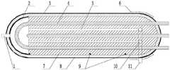
图1为第二级加热器剖面示意图;1 is a schematic cross-sectional view of a second-stage heater;
图2为第二级加热器外形图;Fig. 2 is the outline drawing of the second stage heater;
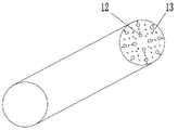
其中,1、燃料入口;2、燃料分配腔;3、金属外壳;4、加热棒;5、燃料通道;6、加热带;7、高温合金热沉块;8、保温材料;9、热电偶;10、汇流槽;11、燃料出口;12、加热棒插孔;13、细长孔。Among them, 1. fuel inlet; 2. fuel distribution cavity; 3. metal shell; 4. heating rod; 5. fuel channel; 6. heating belt; 7. superalloy heat sink block; 8. thermal insulation material; 9. thermocouple ; 10, the confluence groove; 11, the fuel outlet; 12, the heating rod jack; 13, the elongated hole.
具体实施方式Detailed ways
下面结合附图进一步说明本发明。The present invention will be further described below in conjunction with the accompanying drawings.
实施例1Example 1
本发明公开了一种用于模拟主动冷却冲压发动机中碳氢燃料状态的加热装置,此装置采用蓄热式二级加热机构,第一级加热机构设置为加热棒4,通过加热棒4对燃料直接加热,最高温度低于300℃,第二级加热机构设置为高温合金热沉块7,第二级采用加热棒4穿过圆柱体高温合金热沉块7,对高温合金热沉块7进行预先加热,最高温度850℃,一般高温合金热沉块7加热温度比燃料需要温度高出100-200K。The invention discloses a heating device for simulating the state of hydrocarbon fuel in an active cooling ramjet. The device adopts a regenerative two-stage heating mechanism, the first-stage heating mechanism is set as a
本发明的又一实施例,如图1所示,为第二级加热器的剖面示意图,第二级加热机构包括燃料入口1、燃料分配腔2、加热棒4、燃料通道5和金属外壳3,所述金属外壳3形成的内部腔体内设置有高温合金热沉块7,所述加热棒4贯穿设置在高温合金热沉块7内部;所述金属外壳3的一端设置有燃料入口1,金属外壳3的内部设置有燃料分配腔2以及燃料通道5,燃料通道5的末端设置有燃料出口11,燃料沿着燃料入口1进入分配腔,经分配腔流入燃料通道5内,再沿着燃料出口11流出。Another embodiment of the present invention, as shown in FIG. 1 , is a schematic cross-sectional view of a second-stage heater. The second-stage heating mechanism includes a fuel inlet 1 , a
从图1可以看出,第二级加热器的出口端采用半球状结构高温合金热沉块7,加热棒4穿过,并对其加热,所述燃料通道5的末端靠近燃料出口11处设置有汇流槽10,汇流槽10和燃料出口11连通,出口端的汇流槽10尽量做小,如此可以实现第二级加热器中部和出口温度一致,进而保证燃料流经第二级加热器后温度均匀、可控。It can be seen from FIG. 1 that the outlet end of the second-stage heater adopts a hemispherical structure superalloy
本发明的又一实施例,所述高温合金热沉块7中沿着剖面轴向设置有加热棒插孔12和细长孔13,加热棒插孔12的孔径大于细长孔13的孔径,加热棒4插设在加热棒插孔12内,细长孔13作为燃料通道5,如图2所示,为第二级加热器外形效果图,图中大孔为加热棒插孔12用于插加热棒4,小孔为碳氢燃料通道5,此小孔为细长孔13,孔径和长度基本与主动冷却发动机壁面冷却通道一致,一般孔径Φ1.5-Φ3mm,长度为直径的500倍左右。从图中也可以看出,第二级的高温合金热沉块7中加热棒4和细长孔13交叉均匀分布,这有助于确保细长孔13壁面温度一致。In another embodiment of the present invention, the superalloy
本发明的又一实施例,所述高温合金热沉块7的入口端设置为水平端面且与分配腔相邻接,高温合金热沉块7的出口端设置为金属外壳3内壁相适配的半球状结构。第二级加热器的出口端采用半球状结构高温合金热沉块7,加热棒4穿过高温合金热沉块7,并对其加热,保证燃料流经第二级加热器后温度均匀、可控。In yet another embodiment of the present invention, the inlet end of the superalloy
本发明的又一实施例,如图1所示,所述高温合金热沉块7外包裹保温材料8,保温材料8设置为保温涂料或保温棉,保温材料8外包裹金属外壳3。保温材料8对高温合金热沉块7起到较好的保温作用,拓宽了应用范围。In yet another embodiment of the present invention, as shown in FIG. 1 , the superalloy
本发明的又一实施例,如图1所示,所述加热棒4设置为U型加热棒4,其U型加热棒4的弧形端部延伸至燃料分配腔2内。In yet another embodiment of the present invention, as shown in FIG. 1 , the
本发明的又一实施例,所述金属外壳3靠近出口端的外侧壁缠绕设置有加热带6,高温合金热沉块7前端、中部和出口端的外壁上相应设置有热电偶9,在高温合金热沉块7加热温度超过700℃时,启用第二级加热器靠近出口端的金属外壳3上单独缠绕的加热带6,帮助第二级加热器中部和出口温度一致。In another embodiment of the present invention, a
以上所述并非是对本发明的限制,应当指出:对于本技术领域的普通技术人员来说,在不脱离本发明实质范围的前提下,还可以做出若干变化、改型、添加或替换,这些改进和润饰也应视为本发明的保护范围。The above is not a limitation of the present invention, it should be pointed out: for those skilled in the art, under the premise of not departing from the essential scope of the present invention, several changes, modifications, additions or replacements can also be made. Improvements and modifications should also be considered within the scope of the present invention.
Claims (9)
Priority Applications (1)
| Application Number | Priority Date | Filing Date | Title |
|---|---|---|---|
| CN202110136918.9ACN112922743B (en) | 2021-02-01 | 2021-02-01 | A hydrocarbon fuel heating device |
Applications Claiming Priority (1)
| Application Number | Priority Date | Filing Date | Title |
|---|---|---|---|
| CN202110136918.9ACN112922743B (en) | 2021-02-01 | 2021-02-01 | A hydrocarbon fuel heating device |
Publications (2)
| Publication Number | Publication Date |
|---|---|
| CN112922743A CN112922743A (en) | 2021-06-08 |
| CN112922743Btrue CN112922743B (en) | 2022-04-08 |
Family
ID=76169291
Family Applications (1)
| Application Number | Title | Priority Date | Filing Date |
|---|---|---|---|
| CN202110136918.9AActiveCN112922743B (en) | 2021-02-01 | 2021-02-01 | A hydrocarbon fuel heating device |
Country Status (1)
| Country | Link |
|---|---|
| CN (1) | CN112922743B (en) |
Families Citing this family (1)
| Publication number | Priority date | Publication date | Assignee | Title |
|---|---|---|---|---|
| CN115824650A (en)* | 2022-11-30 | 2023-03-21 | 哈尔滨工业大学 | A high-temperature and high-pressure kerosene steam generation device for preventing coking and heat transfer deterioration |
Citations (10)
| Publication number | Priority date | Publication date | Assignee | Title |
|---|---|---|---|---|
| GB1515658A (en)* | 1976-04-23 | 1978-06-28 | Siemens Ag | Heat-exchange units |
| US4512324A (en)* | 1984-04-09 | 1985-04-23 | David Neary | Fuel preheater |
| US5809980A (en)* | 1997-08-29 | 1998-09-22 | F.E.S. Innovations Inc. | Heat exchanger and fuel preheater |
| JP2005122999A (en)* | 2003-10-16 | 2005-05-12 | Sumitomo Electric Ind Ltd | heater |
| CN102770643A (en)* | 2010-02-19 | 2012-11-07 | 丰田自动车株式会社 | Abnormality detection device of fuel property detection device |
| EP2970778A2 (en)* | 2013-03-15 | 2016-01-20 | Foret Plasma Labs, Llc | System, method and apparatus for treating mining byproducts |
| CN106402865A (en)* | 2016-09-29 | 2017-02-15 | 中国科学院力学研究所 | Heater igniter of high-ultrasonic-velocity high-enthalpy ground simulation equipment |
| DE102015218683A1 (en)* | 2015-09-29 | 2017-03-30 | Robert Bosch Gmbh | Fuel heater and manufacturing method therefor |
| CN106568101A (en)* | 2016-10-26 | 2017-04-19 | 西北工业大学 | Supercritical fuel oil heating device in supercritical oil bath type |
| CN108730079A (en)* | 2018-08-20 | 2018-11-02 | 山东宇升电子科技有限公司 | Vehicle oil way heating device |
Family Cites Families (8)
| Publication number | Priority date | Publication date | Assignee | Title |
|---|---|---|---|---|
| DE3581529D1 (en)* | 1984-12-28 | 1991-02-28 | Raychem Corp | METHOD AND DEVICE FOR REGENERATIVE HEATING OF DIESEL FUEL. |
| JP2002228368A (en)* | 2001-02-01 | 2002-08-14 | Mitsubishi Heavy Ind Ltd | Heat accumulation heat exchange device |
| DE102008052918A1 (en)* | 2007-12-21 | 2009-06-25 | Mahle International Gmbh | Heating device for fuel |
| CN102465798A (en)* | 2010-11-17 | 2012-05-23 | 陈明 | Master device of heat accumulating tail gas heat energy recovery micro-emission energy-saving multi-fuel engine |
| CN102425511B (en)* | 2011-12-30 | 2014-11-05 | 中国人民解放军国防科学技术大学 | Hydrocarbon fuel heating method |
| JP6284412B2 (en)* | 2014-04-14 | 2018-02-28 | 古河電気工業株式会社 | Thermal storage fuel heater |
| CN104748111B (en)* | 2015-03-24 | 2017-04-12 | 华南理工大学 | Micro-combustor for metal mesh heat storage and flame stabilization and combustion method thereof |
| CZ307004B6 (en)* | 2016-03-08 | 2017-11-08 | Power Heat Energy S.R.O. | Method of thermal energy production, equipment for this purpose and thermal generation systems |
- 2021
- 2021-02-01CNCN202110136918.9Apatent/CN112922743B/enactiveActive
Patent Citations (10)
| Publication number | Priority date | Publication date | Assignee | Title |
|---|---|---|---|---|
| GB1515658A (en)* | 1976-04-23 | 1978-06-28 | Siemens Ag | Heat-exchange units |
| US4512324A (en)* | 1984-04-09 | 1985-04-23 | David Neary | Fuel preheater |
| US5809980A (en)* | 1997-08-29 | 1998-09-22 | F.E.S. Innovations Inc. | Heat exchanger and fuel preheater |
| JP2005122999A (en)* | 2003-10-16 | 2005-05-12 | Sumitomo Electric Ind Ltd | heater |
| CN102770643A (en)* | 2010-02-19 | 2012-11-07 | 丰田自动车株式会社 | Abnormality detection device of fuel property detection device |
| EP2970778A2 (en)* | 2013-03-15 | 2016-01-20 | Foret Plasma Labs, Llc | System, method and apparatus for treating mining byproducts |
| DE102015218683A1 (en)* | 2015-09-29 | 2017-03-30 | Robert Bosch Gmbh | Fuel heater and manufacturing method therefor |
| CN106402865A (en)* | 2016-09-29 | 2017-02-15 | 中国科学院力学研究所 | Heater igniter of high-ultrasonic-velocity high-enthalpy ground simulation equipment |
| CN106568101A (en)* | 2016-10-26 | 2017-04-19 | 西北工业大学 | Supercritical fuel oil heating device in supercritical oil bath type |
| CN108730079A (en)* | 2018-08-20 | 2018-11-02 | 山东宇升电子科技有限公司 | Vehicle oil way heating device |
Non-Patent Citations (2)
| Title |
|---|
| The development of a portable buoyancy-driven PCR system and itsevaluation by capillary electrophoresis;Zhenqing Li等;《Sensors and Actuators B: Chemical》;20160303;全文* |
| 超临界压力下航空煤油流动与传热特性试验;江晨曦等;《推进技术》;20100415;第31卷(第2期);第230-234页、图1* |
Also Published As
| Publication number | Publication date |
|---|---|
| CN112922743A (en) | 2021-06-08 |
Similar Documents
| Publication | Publication Date | Title |
|---|---|---|
| CN103629013B (en) | A kind of subsonic combustion scramjet combustor and re-generatively cooled method thereof | |
| CN201983931U (en) | Reduced scale thrust chamber for high-pressure and large-heat-flux heat transfer test | |
| CN106066235B (en) | Supercritical water narrow channel natural circulation experimental device and method | |
| CN106403661B (en) | Low-speed cooling water thermal protection device | |
| CN112922743B (en) | A hydrocarbon fuel heating device | |
| CN106568101A (en) | Supercritical fuel oil heating device in supercritical oil bath type | |
| CN106248726A (en) | ORC tests device at 500~2300 DEG C of interval thermal shock/thermal fatigue properties and radiation characteristic | |
| CN206398760U (en) | A kind of microchannel cooling device for rotating detonation engine | |
| Shine et al. | Influence of coolant injector configuration on film cooling effectiveness for gaseous and liquid film coolants | |
| CN102518534B (en) | Hydrocarbon Fuel Heating Devices | |
| CN108298097A (en) | A kind of small scale enhanced heat exchange structure | |
| CN108595746A (en) | A kind of master-plan appraisal procedure of hollow brick storage heater | |
| Tan et al. | Impact of nozzles on the wall-temperature in a valveless pulse detonation engine | |
| CN118111120B (en) | Gas generator for aerospace engine combustion-heat exchange integrated helium heater | |
| CN218628986U (en) | High-temperature high-pressure kerosene steam generation device capable of preventing coking and heat transfer deterioration | |
| CN112614602A (en) | Modeling experiment system and method for stirring characteristics of outlet impact jet flow of sodium-cooled fast reactor core | |
| CN109404162B (en) | Aviation kerosene isobaric two-stage electric heating device | |
| CN108800190B (en) | Test medium mixing device | |
| GB910729A (en) | Heat exchanger | |
| CN109030789A (en) | The heating of salt bath kerosene and cracking simulation experiment method | |
| CN205719474U (en) | Supercritical water narrow passage Natural Circulation experimental provision | |
| CN205279810U (en) | Pipe wing formula solution -air heat exchanger | |
| CN205279811U (en) | Take casing refrigerated pipe wing formula solution -air heat exchanger | |
| CN209115220U (en) | Constant-pressure two-stage electric heating device for aviation kerosene | |
| CN112282972A (en) | Low-pressure sub-super shear flow experiment system with high-temperature subsonic air |
Legal Events
| Date | Code | Title | Description |
|---|---|---|---|
| PB01 | Publication | ||
| PB01 | Publication | ||
| SE01 | Entry into force of request for substantive examination | ||
| SE01 | Entry into force of request for substantive examination | ||
| GR01 | Patent grant | ||
| GR01 | Patent grant |