CN112890913B - Thrombus taking device and thrombus taking device - Google Patents
Thrombus taking device and thrombus taking deviceDownload PDFInfo
- Publication number
- CN112890913B CN112890913BCN201911222564.9ACN201911222564ACN112890913BCN 112890913 BCN112890913 BCN 112890913BCN 201911222564 ACN201911222564 ACN 201911222564ACN 112890913 BCN112890913 BCN 112890913B
- Authority
- CN
- China
- Prior art keywords
- mesh structure
- thrombus
- push
- main body
- mesh
- Prior art date
- Legal status (The legal status is an assumption and is not a legal conclusion. Google has not performed a legal analysis and makes no representation as to the accuracy of the status listed.)
- Active
Links
Images


Classifications
- A—HUMAN NECESSITIES
- A61—MEDICAL OR VETERINARY SCIENCE; HYGIENE
- A61B—DIAGNOSIS; SURGERY; IDENTIFICATION
- A61B17/00—Surgical instruments, devices or methods
- A61B17/22—Implements for squeezing-off ulcers or the like on inner organs of the body; Implements for scraping-out cavities of body organs, e.g. bones; for invasive removal or destruction of calculus using mechanical vibrations; for removing obstructions in blood vessels, not otherwise provided for
- A61B17/221—Gripping devices in the form of loops or baskets for gripping calculi or similar types of obstructions
- A61B2017/2212—Gripping devices in the form of loops or baskets for gripping calculi or similar types of obstructions having a closed distal end, e.g. a loop
Landscapes
- Health & Medical Sciences (AREA)
- Surgery (AREA)
- Life Sciences & Earth Sciences (AREA)
- Heart & Thoracic Surgery (AREA)
- Nuclear Medicine, Radiotherapy & Molecular Imaging (AREA)
- Vascular Medicine (AREA)
- Engineering & Computer Science (AREA)
- Biomedical Technology (AREA)
- Orthopedic Medicine & Surgery (AREA)
- Medical Informatics (AREA)
- Molecular Biology (AREA)
- Animal Behavior & Ethology (AREA)
- General Health & Medical Sciences (AREA)
- Public Health (AREA)
- Veterinary Medicine (AREA)
- Surgical Instruments (AREA)
Abstract
Description
Translated fromChinese技术领域technical field
本发明属于医疗器械技术领域,具体涉及一种取栓器及具有其的取栓装置。The invention belongs to the technical field of medical devices, and in particular relates to a thrombectomy device and a thrombectomy device having the same.
背景技术Background technique
急性缺血性卒中(acute ischemic stroke,AIS,俗称脑梗死)是由于脑部血流的突然阻塞而引起局部脑组织缺血坏死所导致的神经组织损伤。急性缺血性脑卒中是卒中最常见类型,是中老年人致死和致残的主要疾病。尤其是大血管闭塞所致的急性脑卒中,病情凶险,死亡率、致残率高。一旦发生中风,给患者造成巨大身心危害,也给患者家庭及社会造成沉重的负担。Acute ischemic stroke (AIS, commonly known as cerebral infarction) is nerve tissue damage caused by ischemic necrosis of local brain tissue caused by sudden blockage of cerebral blood flow. Acute ischemic stroke is the most common type of stroke, and it is the main cause of death and disability among middle-aged and elderly people. Especially acute cerebral apoplexy caused by large vessel occlusion is dangerous, with high mortality and disability rate. Once a stroke occurs, it will cause huge physical and mental harm to the patient, and also cause a heavy burden to the patient's family and society.
血管的再通是治疗急性缺血性脑卒中的关键。目前治疗急性缺血性脑卒中的常规方法包括两大类:介入溶栓和机械取栓。介入溶栓是导管把溶栓剂注入病变所在的血管内的病灶附近,在病灶局部瞬间形成很高的溶栓剂浓度,加快血栓溶解速度,进而增加血管再通的机会。溶栓治疗只适合于体积较小的血栓,对大体积血栓的效果不理想,在急性大脑中动脉脑梗死中,如果血栓长度超过8mm,静脉溶栓几乎不能再通阻塞的血管,即便是能够再通,再次堵塞的概率也很大。为了解决上述问题,对于超过溶栓时间窗和有溶栓治疗禁忌症的患者,可采用机械装置清除血栓,此方法因能够快速使闭塞的血管再通,提高血管再通率,减少溶栓药物剂量,降低症状性脑出血的发生率,延长治疗时间窗,缩短再通时间,从而为可逆的缺血脑组织争取更多的时间,明显改善患者的预后。Vascular recanalization is the key to the treatment of acute ischemic stroke. The current conventional methods for the treatment of acute ischemic stroke include two categories: interventional thrombolysis and mechanical thrombectomy. Interventional thrombolysis is a catheter that injects a thrombolytic agent into the vicinity of the lesion in the blood vessel where the lesion is located, and instantly forms a high concentration of thrombolytic agent in the local lesion, which accelerates the rate of thrombus dissolution, thereby increasing the chance of vascular recanalization. Thrombolytic therapy is only suitable for small thrombus, and the effect on large thrombus is not ideal. In acute middle cerebral artery cerebral infarction, if the thrombus length exceeds 8 mm, intravenous thrombolysis can hardly re-open the blocked blood vessel, even if it can Re-opening, the probability of blocking again is also very high. In order to solve the above problems, for patients who have exceeded the thrombolytic time window and have contraindications to thrombolytic therapy, mechanical devices can be used to remove thrombus. Dosage can reduce the incidence of symptomatic intracerebral hemorrhage, prolong the treatment time window, and shorten the recanalization time, so as to gain more time for reversible ischemic brain tissue and significantly improve the prognosis of patients.
其中,现市场上可用的取栓产品有MERCITM、PENUMBRATM、TREVOTM、SOLITAIRETM。这些产品在运用过程中都忽略了血栓的性能和种类,血栓有硬血栓和软血栓,硬血栓粘、弹性强、难压缩,软血栓易碎。现有的取栓器械依靠自身的径向力,使得取栓器嵌入血栓的内部,从而达到捕获血栓的目的。然而这种方式对于较柔顺的血栓(红血栓)尚且有效,但是对于较硬的血栓(白血栓)由于现有取栓器的自身径向力不足,导致难以压缩硬血栓,从而造成难以捕获并取出硬血栓的问题,而大部分的脑卒中的血栓栓塞是由硬血栓引起的。Among them, the thrombectomy products available on the market are MERCITM , PENUMBRATM , TREVOTM , SOLITAIRETM . These products ignore the properties and types of thrombus in the process of application. The thrombus includes hard thrombus and soft thrombus. Hard thrombus is sticky, elastic and difficult to compress, while soft thrombus is fragile. The existing thrombectomy device relies on its own radial force to make the thrombectomy device embedded in the thrombus, so as to achieve the purpose of capturing the thrombus. However, this method is still effective for softer thrombus (red thrombus), but for harder thrombus (white thrombus), due to insufficient radial force of the existing thrombectomy device, it is difficult to compress the hard thrombus, thus making it difficult to capture and prevent the thrombus. The problem of removing the hard thrombus, and most of the thromboembolism in stroke is caused by the hard thrombus.
发明内容SUMMARY OF THE INVENTION
本发明的目的是至少解决现有取栓设备在取栓过程中由于自身径向力不足而造成无法捕获血栓的问题。The purpose of the present invention is to at least solve the problem that the existing thrombectomy device cannot capture the thrombus due to its insufficient radial force during the thrombectomy process.
本发明提出了一种取栓器,所述取栓器包括:The present invention provides a thrombectomy device, which comprises:
支架主体,所述支架主体包括至少一段网状结构;a stent body, the stent body comprising at least one section of a mesh structure;
限位件,所述限位件与所述支架主体的近端相连,并用于对所述支架主体的近端进行限位;a limiter, the limiter is connected to the proximal end of the bracket body and used to limit the proximal end of the bracket body;
推拉件,所述推拉件与所述支架主体相连,所述支架主体在所述推拉件的作用下具有收缩状态和展开状态,其中,所述支架主体的远端能够在所述推拉件的作用下朝向所述限位件运动,以缩短所述支架主体的近端和远端之间的距离。A push-pull member, the push-pull member is connected to the stent body, the stent body has a retracted state and an expanded state under the action of the push-pull member, wherein the distal end of the stent body can be under the action of the push-pull member Move downward toward the limiter to shorten the distance between the proximal end and the distal end of the stent body.
根据本发明中的取栓器,通过限位件对支架主体的近端进行限位,并将推拉件与支架主体相连,当需要取出血管内的血栓时,首先将处于收缩状态的取栓器移送至病灶部位,由于支架主体的近端受限位件限位,当支架主体的远端在推拉件的作用下朝向限位件移动时,即朝向支架主体的近端移动时,缩短了支架主体的整体长度,从而使网状结构受轴向挤压后沿径向方向向外扩张,处于展开状态,从而挤压并捕获血栓。当遇到硬血栓时,可进一步地缩回推拉件,使支架主体的整体长度进一步地缩减,从而使网状结构继续沿径向方向向外扩张,提高支架主体的径向力,使硬血栓在支架主体的径向力的作用下脱水变小,硬血栓更容易进入支架主体内部,并最终随取栓器共同排出体外,从而使闭塞的血管再通,提高血管再通率,延长治疗时间窗,缩短再通时间,从而为可逆的缺血脑组织争取更多的时间,明显改善患者的预后。According to the thrombectomy device of the present invention, the proximal end of the stent body is limited by the limiting member, and the push-pull member is connected to the stent body. When it is transferred to the lesion site, due to the limitation of the proximal limiter of the stent body, when the distal end of the stent body moves toward the limiter under the action of the push-pull member, that is, moves toward the proximal end of the stent body, the stent shortens. The overall length of the main body, so that the mesh structure expands outward in the radial direction after being squeezed axially, and is in a deployed state, thereby squeezing and capturing the thrombus. When a hard thrombus is encountered, the push-pull member can be further retracted to further reduce the overall length of the stent body, so that the mesh structure continues to expand outward in the radial direction, and the radial force of the stent body is increased, so that the hard thrombus can be further reduced. Under the action of the radial force of the stent body, the dehydration becomes smaller, and the hard thrombus is more likely to enter into the stent body and finally be excreted together with the thrombectomy device, thereby recanalizing the occluded blood vessel, improving the blood vessel recanalization rate and prolonging the treatment time. Window, shorten the recanalization time, so as to buy more time for reversible ischemic brain tissue, significantly improve the prognosis of patients.
另外,根据本发明的取栓器,还可具有如下附加的技术特征:In addition, the thrombectomy device according to the present invention may also have the following additional technical features:
在本发明的一些实施方式中,所述支架主体结构包括沿所述支架主体的远端朝向所述支架主体的近端依次顺序设置的第一网状结构、第二网状结构和第三网状结构。In some embodiments of the present invention, the stent body structure includes a first mesh structure, a second mesh structure and a third mesh that are sequentially arranged along the distal end of the stent body toward the proximal end of the stent body. like structure.
在本发明的一些实施方式中,当所述支架主体处于压缩状态时,所述第二网状结构的长度大于所述第三网状结构的长度,所述第三网状结构的长度大于所述第一网状结构的长度。In some embodiments of the present invention, when the stent body is in a compressed state, the length of the second mesh structure is greater than the length of the third mesh structure, and the length of the third mesh structure is greater than the length of the third mesh structure. the length of the first mesh structure.
在本发明的一些实施方式中,所述第一网状结构、所述第二网状结构和所述第三网状结构分别由多个网孔组成,且所述第二网状结构的网孔数量小于所述第三网状结构的网孔数量。In some embodiments of the present invention, the first mesh structure, the second mesh structure and the third mesh structure are respectively composed of a plurality of mesh holes, and the meshes of the second mesh structure The number of holes is smaller than the number of mesh holes of the third mesh structure.
在本发明的一些实施方式中,所述第一网状结构、所述第二网状结构和所述第三网状结构分别由多个网孔组成,所述第二网状结构的网孔平均面积大于所述第一网状结构的网孔平均面积,所述第三网状结构的网孔平均面积大于或等于所述第二网状结构的网孔平均面积。In some embodiments of the present invention, the first mesh structure, the second mesh structure and the third mesh structure are respectively composed of a plurality of mesh holes, and the mesh holes of the second mesh structure The average area is greater than the average area of the meshes of the first mesh structure, and the average area of the meshes of the third mesh structure is greater than or equal to the average area of the meshes of the second mesh structure.
在本发明的一些实施方式中,所述推拉件的数量为一个,所述推拉件与所述第一网状结构的远端相连,或者所述推拉件与所述第二网状结构的远端相连;或者,In some embodiments of the present invention, the number of the push-pull member is one, the push-pull member is connected to the distal end of the first mesh structure, or the push-pull member is connected to the distal end of the second mesh structure connected end-to-end; or,
所述推拉件的数量为三个,所述三个推拉件分别与所述第一网状结构的远端、所述第二网状结构的远端和所述第三网状结构的远端相连。The number of the push-pull parts is three, and the three push-pull parts are respectively connected to the distal end of the first mesh structure, the distal end of the second mesh structure, and the distal end of the third mesh structure. connected.
在本发明的一些实施方式中,所述取栓器还包括第一搭接部和第二搭接部,所述第一网状结构通过第一搭接部与所述第二网状结构相连,所述第二网状结构通过第二搭接部与所述第三网状结构相连,所述第一搭接部和所述第二搭接部能够相对所述推拉件沿轴向运动。In some embodiments of the present invention, the thrombus remover further includes a first overlapping portion and a second overlapping portion, and the first mesh structure is connected to the second mesh structure through the first overlapping portion , the second mesh structure is connected with the third mesh structure through a second overlapping portion, and the first overlapping portion and the second overlapping portion can move relative to the push-pull member in the axial direction.
在本发明的一些实施方式中,所述支架主体由两个网状结构组成,其中一网状结构的近端与另一网状结构的远端相连,形成连接处,所述推拉件与所述支架本体的远端相连,或者所述推拉件与所述连接处相连。In some embodiments of the present invention, the stent body is composed of two mesh structures, wherein the proximal end of one mesh structure is connected with the distal end of the other mesh structure to form a connection, and the push-pull member is connected to the The distal end of the bracket body is connected, or the push-pull member is connected with the connection.
在本发明的一些实施方式中,所述至少一段网状结构的远端张角和近端张角均大于30°。In some embodiments of the present invention, both the distal opening angle and the proximal opening angle of the at least one segment of the mesh structure are greater than 30°.
本发明的另一方面还提出了一种取栓装置,所述取栓装置具有导管和取栓器,所述取栓器具有设于所述导管内的压缩状态和设于所述导管外的展开状态,其中,所述取栓器为上述任一项所述的取栓器。Another aspect of the present invention also provides a thrombectomy device, which has a catheter and a thrombus retriever, and the thrombus retriever has a compressed state provided inside the catheter and a thrombectomy device provided outside the catheter. In a deployed state, the thrombus retriever is the thrombus retriever described in any one of the above.
附图说明Description of drawings
通过阅读下文优选实施方式的详细描述,各种其它的优点和益处对于本领域普通技术人员将变得清楚明了。附图仅用于示出优选实施方式的目的,而并不认为是对本发明的限制。而且在整个附图中,用相同的附图标记表示相同的部件。其中:Various other advantages and benefits will become apparent to those of ordinary skill in the art upon reading the following detailed description of the preferred embodiments. The drawings are for the purpose of illustrating preferred embodiments only and are not to be considered limiting of the invention. Also, the same components are denoted by the same reference numerals throughout the drawings. in:
图1为本发明中一实施方式的取栓器处于展开状态的结构示意图;1 is a schematic structural diagram of a thrombectomy device in an unfolded state according to an embodiment of the present invention;
图2为图1中取栓器处于压缩状态的结构示意图;Fig. 2 is the structural representation that the thrombectomy device in Fig. 1 is in the compressed state;
图3为图1中取栓器处于展开至极限状态时的结构示意图;Fig. 3 is the structural representation when the thrombectomy device in Fig. 1 is unfolded to the limit state;
图4为图1中取栓器进行取栓过程时压缩状态的结构示意图;Fig. 4 is the structural representation of the compressed state when the thrombectomy device in Fig. 1 carries out the thrombus removal process;
图5为图1中取栓器进行取栓过程时展开状态的结构示意图;Fig. 5 is the structural representation of the unfolded state when the thrombectomy device in Fig. 1 carries out the thrombus removal process;
图6为图1中取栓器进行取栓过程时进一步展开状态的结构示意图;Fig. 6 is the structural representation of the further unfolded state when the thrombectomy device in Fig. 1 performs the thrombus removal process;
图7为本发明另一实施方式的取栓器处于展开状态的结构示意图;7 is a schematic structural diagram of a thrombectomy device in a deployed state according to another embodiment of the present invention;
图8为本发明另一实施方式的取栓器处于展开状态的结构示意图;8 is a schematic structural diagram of a thrombectomy device in a deployed state according to another embodiment of the present invention;
图9为本发明另一实施方式的取栓器处于展开状态的结构示意图;9 is a schematic structural diagram of a thrombectomy device in a deployed state according to another embodiment of the present invention;
图10为本发明另一实施方式的取栓器处于展开状态的结构示意图。FIG. 10 is a schematic structural diagram of a thrombectomy device in a deployed state according to another embodiment of the present invention.
附图中各标号表示如下:The reference numbers in the accompanying drawings are as follows:
100:取栓器;100: thrombectomy device;
10:支架主体、11:第一网状结构、12:第二网状结构、13:第三网状结构;10: stent body, 11: first mesh structure, 12: second mesh structure, 13: third mesh structure;
20:限位件;20: limit piece;
30:推拉件;30: push-pull parts;
41:第一搭接部、42:第二搭接部;41: the first lap joint, 42: the second lap joint;
50:端头;50: end;
200:导管;200: catheter;
300:血管;300: blood vessels;
400:血栓。400: Thrombosis.
具体实施方式Detailed ways
下面将参照附图更详细地描述本发明的示例性实施方式。虽然附图中显示了本发明的示例性实施方式,然而应当理解,可以以各种形式实现本发明而不应被这里阐述的实施方式所限制。相反,提供这些实施方式是为了能够更透彻地理解本发明,并且能够将本发明的范围完整的传达给本领域的技术人员。Exemplary embodiments of the present invention will be described in more detail below with reference to the accompanying drawings. While exemplary embodiments of the present invention are shown in the drawings, it should be understood that the present invention may be embodied in various forms and should not be limited by the embodiments set forth herein. Rather, these embodiments are provided so that the present invention will be more thoroughly understood, and will fully convey the scope of the present invention to those skilled in the art.
应理解的是,文中使用的术语仅出于描述特定示例实施方式的目的,而无意于进行限制。除非上下文另外明确地指出,否则如文中使用的单数形式“一”、“一个”以及“所述”也可以表示包括复数形式。术语“包括”、“包含”、“含有”以及“具有”是包含性的,并且因此指明所陈述的特征、步骤、操作、元件和/或部件的存在,但并不排除存在或者添加一个或多个其它特征、步骤、操作、元件、部件、和/或它们的组合。文中描述的方法步骤、过程、以及操作不解释为必须要求它们以所描述或说明的特定顺序执行,除非明确指出执行顺序。还应当理解,可以使用另外或者替代的步骤。It is to be understood that the terminology used herein is for the purpose of describing particular example embodiments only and is not intended to be limiting. As used herein, the singular forms "a," "an," and "the" can also be intended to include the plural forms unless the context clearly dictates otherwise. The terms "comprising", "comprising", "containing" and "having" are inclusive and thus indicate the presence of stated features, steps, operations, elements and/or components, but do not preclude the presence or addition of one or Various other features, steps, operations, elements, components, and/or combinations thereof. Method steps, procedures, and operations described herein are not to be construed as requiring that they be performed in the particular order described or illustrated, unless an order of performance is explicitly indicated. It should also be understood that additional or alternative steps may be used.
尽管可以在文中使用术语第一、第二、第三等来描述多个元件、部件、区域、层和/或部段,但是,这些元件、部件、区域、层和/或部段不应被这些术语所限制。这些术语可以仅用来将一个元件、部件、区域、层或部段与另一区域、层或部段区分开。除非上下文明确地指出,否则诸如“第一”、“第二”之类的术语以及其它数字术语在文中使用时并不暗示顺序或者次序。因此,以下讨论的第一元件、部件、区域、层或部段在不脱离示例实施方式的教导的情况下可以被称作第二元件、部件、区域、层或部段。Although the terms first, second, third, etc. may be used herein to describe various elements, components, regions, layers and/or sections, these elements, components, regions, layers and/or sections should not be restricted by these terms. These terms may only be used to distinguish one element, component, region, layer or section from another region, layer or section. Terms such as "first," "second," and other numerical terms when used herein do not imply a sequence or order unless clearly indicated by the context. Thus, a first element, component, region, layer or section discussed below could be termed a second element, component, region, layer or section without departing from the teachings of example embodiments.
为了便于描述,可以在文中使用空间相对关系术语来描述如图中示出的一个元件或者特征相对于另一元件或者特征的关系,这些相对关系术语例如为“内部”、“外部”、“内侧”、“外侧”、“下面”、“下方”、“上面”、“上方”等。这种空间相对关系术语意于包括除图中描绘的方位之外的在使用或者操作中装置的不同方位。例如,如果在图中的装置翻转,那么描述为“在其它元件或者特征下面”或者“在其它元件或者特征下方”的元件将随后定向为“在其它元件或者特征上面”或者“在其它元件或者特征上方”。因此,示例术语“在……下方”可以包括在上和在下的方位。装置可以另外定向(旋转90度或者在其它方向)并且文中使用的空间相对关系描述符相应地进行解释。For ease of description, spatially relative terms may be used herein to describe the relationship of one element or feature to another element or feature as shown in the figures, such as "inner", "outer", "inner" ", "outside", "below", "below", "above", "above", etc. This spatially relative term is intended to include different orientations of the device in use or operation other than the orientation depicted in the figures. For example, if the device in the figures is turned over, elements described as "below" or "beneath" other elements or features would then be oriented "above" or "above the other elements or features" above features". Thus, the example term "below" can encompass both an orientation of above and below. The device may be otherwise oriented (rotated 90 degrees or at other orientations) and the spatially relative descriptors used herein interpreted accordingly.
为了便于描述,以下描述使用术语“近端”和“远端”,其中“近端”是指的是离操作者近的一端,“远端”是指远离操作者的一端,短语“轴向方向”,本发明里应当被理解成表示本取栓装置被推进和推出的方向,与“轴向垂直”相垂直的方向定义为“径向方向”,短语“长度方向”应当被理解为取栓器物理尺寸最长的方向,与“长度方向”相垂直的方向定义为“径向方向”。For ease of description, the following description uses the terms "proximal" and "distal", where "proximal" refers to the end closest to the operator, "distal" refers to the end away from the operator, and the phrase "axial" "direction", in the present invention, should be understood to mean the direction in which the bolt removal device is pushed and pushed out, the direction perpendicular to the "axial vertical" is defined as "radial direction", and the phrase "length direction" should be understood as the direction of taking The direction with the longest physical dimension of the plug, and the direction perpendicular to the "length direction" is defined as the "radial direction".
实施方式一Embodiment 1
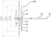
图1为本发明中一实施方式的取栓器100处于展开状态的结构示意图。图2为图1中取栓器100处于压缩状态的结构示意图。图3为图1中取栓器100处于展开至极限状态时的结构示意图。如图1、图2和图3所示,本实施方式中的取栓器100包括支架主体10和限位件20。支架主体20包括至少一段网状结构,限位件20与支架主体10的近端相连,限位件20的近端延伸至体外,从而使操作者在体外对处于体内的支架主体10的近端进行限位。其中,支架主体10与推拉件30相连,至少一段网状结构在推拉件30的作用下具有收缩状态和展开状态,支架主体10的远端能够在推拉件30的作用下朝向限位件20运动,以缩短支架主体10的近端和远端的距离,或者支架主体10的远端能够在推拉件30的作用下朝着远离限位件20的方向运动,以增加支架主体10的近端和远端的距离。FIG. 1 is a schematic structural diagram of a
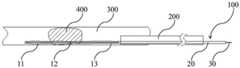
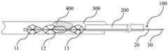
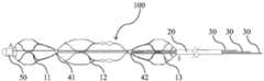
根据本发明中的取栓器10,通过限位件20对支架主体10的近端进行限位,并将推拉件30与支架主体10相连,当需要取出血管300内的血栓400时,首先将处于收缩状态的取栓器100移送至病灶部位,此时取栓器100的状态如图4所示。由于支架主体10的近端受限位件20限位,当支架主体10的远端在推拉件30的作用下朝向限位件20移动时,即朝向支架主体10的近端移动时,缩短了支架主体10的整体长度,从而使网状结构轴向受挤压后沿径向方向向外扩张,处于展开状态,此时取栓器100的状态如图5所示,从而挤压并捕获血栓400。当遇到较硬血栓(血栓中的一种)400时,由于在支架主体10膨胀后,硬血栓400被限制在支架主体10与血管300内壁之间,可进一步地回拉推拉件30,使支架主体10的整体长度进一步地缩减,从而使网状结构继续沿径向方向向外扩张,此时取栓器100的状态如图6所示,图6中箭头所示方向即为推拉件30的进一步收回方向,从而提高支架主体10的径向力使硬血栓400在支架主体10的径向力的作用下脱水变小,硬血栓更容易进入支架主体10内部,达到捕获硬血栓400的目的,随取栓器100共同排出体外,从而使闭塞的血管300再通,提高血管300再通率,延长治疗时间窗,缩短再通时间,从而为可逆的缺血脑组织争取更多的时间,明显改善患者的预后。According to the
取栓器100为近端与远端均封闭的整体式自膨式支架结构,该自膨式支架结构通过激光切割具有形状记忆效应和超弹性的金属管材(如NiTi合金管)而形成并经过模具成型,再经过热处理定型。The
当需要对血栓400进行取出时,将推拉件30与取栓器100连接在一起,连接方式没有限制,可以为焊接,胶接,卯接,压接等方式。连接好的推拉件30和取栓器100被压入导管内。取栓器100在导管200内形成压缩状态,取栓器100可通过推拉件30的推拉而在收回位置和展开位置之间转化。在收回位置,取栓器100收回到导管200内,处于压缩状态。在展开位置时,取栓器100被推出到导管200外,从而通过自身膨胀形成展开状态,处于展开状态的取栓器100可以直接取出软血栓(血栓的一种)400。当遇到硬血栓400时,通过进一步地收回推拉件30,使支架主体10的整体长度进一步地缩减,从而使网状结构继续沿径向方向向外扩张,提高支架主体10的径向力,使硬血栓400在支架主体10的径向力的作用下脱水变小,随取栓器100共同排出体外。When the
导管200的远端有显影标记,显影标记为原子质量比大的金属材料或者稀土材料,例如金、铂、铊、钽等材料。手术中,显影标记点在CT血管造影(CTA)、MRA(磁共振血管造影)等设备下可以显示出导管200到达的位置,从而准确的控制取栓装置与血栓400间的关系。The distal end of the
取栓装置通过微创手术经过血管从体外到达血栓处,从血栓400的近端穿过血栓400,在CT和/或MRA,DSA等造影设备观察下,确定导管200与血栓400间的相对位置。固定好推拉件30和限位件20后,回撤导管200,在造影设备下观察显影标记,从而可知导管200在体内回撤的路径。压缩状态的支架主体100脱离导管200内后恢复至自然状态,即展开状态。在限位件20的限位作用下,支架主体100的网状结构开始膨胀,通过网状结构自身膨胀的径向力,使网状结构渗透进入血栓400,与血栓400充分接触,收回推拉件30,在推拉件30的拽动下,支架主体100带动血栓400一起向操作者近端运动,并最终使取栓器100和血栓400共同回撤到导管200内,再整体向近端撤出导管200及导管200内的取栓器100和血栓至患者体外,从而取栓装置整个取栓过程完成。The thrombectomy device reaches the thrombus from outside the body through a blood vessel through a minimally invasive operation, and passes through the
当支架主体100通过网状结构自身膨胀的径向力无法渗透进入硬血栓400内时,则通过收回推拉件30,使支架主体10的整体长度进一步地缩减,从而使网状结构继续沿径向方向向外扩张。一方面扩张后的网状结构能够进一步地挤压硬血栓400,使得硬血栓400脱水后尺寸变小,另一方面网状结构充分扩张后网口直径变大,从而使得硬血栓400能够进入取栓器100的框架内,从而达到捕获硬血栓400的目的,并随取栓器100共同排出体外。其中,推拉件30可以采用具有较好弹性的金属,包括不锈钢、镍钛合金、钴铬合金等。When the
本实施方式中的限位件20为具有内腔的结构,推拉件30能够穿过限位件20的内腔与支架主体100的远端相连。在本发明的其它实施方式中,若限位件20无内腔结构,则可以将推拉件30沿限位件20的外表面伸出并与支架主体10的远端相连,且推拉件30能够相对限位件20运动,从而保证推拉件30推拉支架主体100运动时,限位件20能够对支架主体10起到限位作用。The limiting
如图1所示,本实施方式中的至少一段网状结构包括沿支架主体10的远端朝向支架主体10的近端依次顺序设置的第一网状结构11、第二网状结构12和第三网状结构13。As shown in FIG. 1 , at least one section of the mesh structure in this embodiment includes a
其中,第一网状结构11、第二网状结构12和第三网状结构13分别在取栓过程中拥有各自不同的作用,第一网状结构11的远端较血栓400的远端更远,其功能为防止血栓400被捕捉后逃脱。第二网状结构12的功能为捕获血栓400。第三网状结构13辅助第二网状结构12捕获血栓400。通过第一网状结构11、第二网状结构12和第三网状结构13相互配合,能够提高取栓器100的柔顺性,防止血栓400发生碎裂,从而更加精确的捕获血栓400。Wherein, the
第一网状结构11、第二网状结构12和第三网状结构13分别由多个网孔组成,且第二网状结构12的网孔数量少于第三网状结构13的网孔数量。具体的,The
第二网状结构12具有较稀疏的网孔结构,在一个圆周方向具有2~4个网孔,从而便于血栓400落入第二网状结构12的网孔内。同时,为了为防止血栓400从取栓器100中脱落,第一网状结构11具有较密的网孔,在一个圆周方向具有3~8个网孔第二网状结构。第三网状结构13在一个圆周方向具有2~4个网孔,辅助第二网状结构12捕获血栓400第一网状结构。The
为了进一步地提高第二网状结构12的径向支撑力,从而更好的挤压硬血栓400并捕获硬血栓400,第二网状结构12在支架主体10处于展开状态时应具有最大径向尺寸。如图2所示,当支架主体10处于压缩状态时,第二网状结构12的长度D2大于第三网状结构13的长度D3,第三网状结构13的长度D3大于第一网状结构11的长度D1。如图3所示,当保持限位件20固定,向近端方向收回推拉件30使第一网状结构11的远端朝向第二网状结构12靠近,第二网状结构12的远端朝向第三网状结构13靠近,第三网状结构13的远端朝向限位件20靠近,从而使第一网状结构11具有最大径向尺寸D4,第二网状结构12具有最大径向尺寸D5,第三网状结构13具有最大径向尺寸D6,且第二网状结构12的径向尺寸D5大于第三网状结构13的径向尺寸D6,第三网状结构13的径向尺寸D6大于第一网状结构11的径向尺寸D4,从而提高第二网状结构12的径向支撑力。In order to further improve the radial support force of the
本实施方式中第三网状结构13的近端与限位件20的远端连接。连接方式可以为焊接、粘接、压铆等,此处不做限定。第一网状结构11、第二网状结构12和第三网状结构13均具有各自的近端和远端,相邻两个网状结构的较远端的网状结构的近端与较近端的网状结构的远端相连接形成搭接部,第一网状结构11通过第一搭接部41与第二网状结构12相连,第二网状结构12通过第二搭接部42与第三网状结构13相连,第一搭接部41和第二搭接部42能够相对推拉件30沿轴向方向运动,形成搭接部的连接方式可以为焊接、粘接、压铆等,此处不做限定。In this embodiment, the proximal end of the
其中,第一搭接部41和第二搭接部42的中心设有通孔,推拉件30的远端能够穿过第一搭接部41和第二搭接部42的中心通孔与第一网状结构11的远端相连,并形成端头50,其具体的连接方式可以为焊接、粘接、压铆等,此处不做限定。The center of the first overlapping
再次参看图1,本实施方式中,取栓器100的总长度为第一网状结构11的远端至第三网状结构13的近端的长度,其中L1为本实施方式中的取栓器100的有效取栓区间。取栓器100的有效取栓区间越大,则取栓器100的取栓效率越高。在进行取栓手术时,应保证血栓400在L1的范围之内。第一网状结构11的远端在展开状态具有张角A,为充分提升取栓器100的有效区间长度L1,应保证张角A>30°。第三网状结构13的近端在展开状态具有张角B,为充分提升取栓器100的有效区间长度L1,应保证张角B>30°。Referring to FIG. 1 again, in this embodiment, the total length of the
实施方式二Embodiment 2
图7为本发明另一实施方式的取栓器100处于展开状态的结构示意图。如图7所示,本实施方式中的取栓器100的大部分结构与实施方式一相同,不同的是支架主体10的各个网状结构结构均采用编织网结构。各个网状结构的编织网具有1~20根独立的丝材交织而成。该丝材具有较好的弹性,可以采用镍钛合金、钴铬合金、不锈钢等材质制成。FIG. 7 is a schematic structural diagram of a
在本实施方式中第一网状结构11、第二网状结构12和第三网状结构13分别由多个网孔组成,其中,第二网状结构12的网孔平均面积大于第一网状结构11的网孔平均面积,第三网状结构13的网孔平均面积大于或等于第二网状结构12的网孔平均面积。这里的网孔平均面积是指所有网孔的面积与网孔的数量之间的比值。In this embodiment, the
为实现上述规律的网眼分布,具有两种实施方式。一种实施方式为:将第一网状结构11、第二网状结构12和第三网状结构13的编织网采用相同数量的丝材进行编织。在自然状态下,第一网状结构11的长度小于第二网状结构12的长度,第二网状结构12的长度小于第三网状结构13的长度,从而使第二网状结构12的网孔平均面积大于第一网状结构11的网孔平均面积,第三网状结构13的网孔平均面积大于第二网状结构12的网孔平均面积。或者第一网状结构11的长度小于第二网状结构12的长度,第二网状结构12的长度等于第三网状结构13的长度,从而使第二网状结构12的网孔平均面积大于第一网状结构11的网孔面积,第三网状结构13的网孔平均面积等于第二网状结构12的网孔平均面积。To achieve the above-mentioned regular mesh distribution, there are two implementations. An embodiment is as follows: the woven meshes of the
为实现上述规律的网眼分布,另外一种实施方式为:第一网状结构11的长度等于第二网状结构12的长度,且等于第三网状结构13的的长度。第一网状结构11的独立丝材数量大于第二网状结构12的独立丝材数量,第二网状结构12的独立丝材数量大于第三网状结构13的独立丝材数量,从而使第二网状结构12的网孔平均面积大于第一网状结构11的网孔平均面积,第三网状结构13的网孔平均面积大于第二网状结构12的网孔平均面积。或者,第一网状结构11的独立丝材数量大于第二网状结构12的,第二网状结构12的独立丝材数量等于第三网状结构13的独立丝材数量,从而使第二网状结构12的网孔平均面积大于第一网状结构11的网孔平均面积,第三网状结构13的网孔平均面积等于第二网状结构12的网孔平均面积。In order to achieve the above-mentioned regular mesh distribution, another embodiment is: the length of the
实施方式三Embodiment 3
图8为本发明另一实施方式的取栓器100处于展开状态的结构示意图。如图8所示,本实施方式中的取栓器100的大部分结构与实施方式一相同,仅推拉件30的设置数量不同。本实施方式中的推拉件30的数量为三个,三个推拉件30分别与第一网状结构11的远端、第二网状结构12的远端和第三网状结构13的远端相连。为便于连接,三个推拉件30可分别与端头50、第一搭接部41和第二搭接部42相连,从而可以单独控制各个网状结构的状态,也可以通过三个推拉件30相互配合推拉,使第一网状结构11、第二网状结构12和第三网状结构13能够同时具有多种形态,从而进一步地提升支架主体10的支撑力和柔顺性,满足各种类型血栓的捕获需求。FIG. 8 is a schematic structural diagram of a
当然,本实施方式中的推拉件30的设置方式也可以应用于实施方式二中。Of course, the arrangement of the push-
实施方式四Embodiment 4
图9为本发明另一实施方式的取栓器100处于展开状态的结构示意图,如图9所示,本实施方式中的取栓器100的大部分结构与实施方式一相同,仅推拉件30与支架主体10的连接位置不同。FIG. 9 is a schematic structural diagram of the
如图9所示,本实施方式中的推拉件30的数量为一个,推拉件30与第二网状结构12的远端相连。此时推拉件30可以控制支架主体10的第二网状结构12与第三网状结构13。当取栓器100从导管200中释放后,无论如何拉动或推动推拉件30,第一网状结构11始终处于膨胀状态,从而有效地防止血栓400从取栓器100的远端脱落。As shown in FIG. 9 , the number of the push-
当然,本实施方式中的推拉件30与支架主体10的连接方式也可以应用于实施方式二中。Of course, the connection between the push-
实施方式五Embodiment 5
图10为本发明另一实施方式的取栓器100处于展开状态的结构示意图,如图10所示,本实施方式中的取栓器100仅设置一个网状结构,优选的,可选取第二网状结构12的结构。第二网状结构12的网孔较大,能够较容易捕获硬血栓400。本实施方式中,通过端头50将推拉件30的远端与第二网状结构12的远端相连,从而控制第二网状结构12运动。第二网状结构12的近端通过第一搭接部41与限位件20相连,从而对第二网状结构12的近端进行封闭并对第二网状结构12进行限位。或者不设置第一搭接部41,第二网状结构12的近端直接与限位件20相连。其具体工作方式与实施方式一相同。FIG. 10 is a schematic structural diagram of the
在本发明的其它实施方式中,还可以在支架主体10上设置两个或超过三个的网状结构,其具体设置形式均可应用上述实施方式一至实施方式四中的具体结构。设置一个网状结构的支架主体与设置多个网状结构的支架主体相比,在支架主体处于自然膨胀状态下具有相同的轴向长度的前提下,在支架主体处于较为弯曲的血管环境中,设置一个网状结构的支架主体容易出现“香蕉”效应,即支架主体膨胀后呈弧形弯曲,支架主体不能充分与血管壁贴合,从而导致对血栓的压迫力减小,不利于取栓。而设置多个结构的支架主体膨胀后,能够较好地适应弯曲的血管环境,不易出现“香蕉”效应,同时柔顺性较一个网状结构的支架主体好,更容易通过弯曲的血管环境。In other embodiments of the present invention, two or more than three mesh structures may also be provided on the stent
在其他实施例中,支架主体10上设置两个的网状结构,其中一网状结构的近端与另一网状结构的远端相连,形成连接处,推拉件与支架本体的远端相连,或者推拉件与连接处相连。其中,推拉件与连接处相连的方式与图9类似,也就是图9中的取栓支架去掉第三网状结构13。In other embodiments, the
本发明的另一方面还提出了一种取栓装置,取栓装置具有导管200和取栓器100,取栓器100具有设于导管200内的压缩状态和设于导管200外的展开状态,其中,取栓器100为上述任一项实施方式中的取栓器100。Another aspect of the present invention also provides a thrombectomy device, the thrombectomy device has a
根据本发明中的取栓装置,通过在取栓器内设置限位件20,并通过限位件20对支架主体10的近端进行限位,并将推拉件30与支架主体10相连,当需要取出血管300内的血栓400时,首先将处于收缩状态的取栓器100移送至病灶部位,此时取栓器100的状态如图4所示。由于支架主体10的近端受限位件20限位,当支架主体10的远端在推拉件30的作用下朝向限位件20移动时,即朝向支架主体10的近端移动时,缩短了支架主体10的整体长度,从而使网状结构受挤压后沿径向方向向外扩张,处于展开状态,此时取栓器100的状态如图5所示,从而挤压并捕获血栓400。当遇到较硬血栓(血栓中的一种)400时,可进一步地缩回推拉件30,使支架主体10的整体长度进一步地缩减,从而使网状结构继续沿径向方向向外扩张,此时取栓器100的状态如图6所示,图6中箭头所示方向即为推拉件30的进一步收回方向,从而提高支架主体10的径向力,使硬血栓400在支架主体10的径向力的作用下脱水变小,硬血栓更容易进入支架主体内部,随取栓器100共同排出体外,从而使闭塞的血管300再通,提高血管300再通率,延长治疗时间窗,缩短再通时间,从而为可逆的缺血脑组织争取更多的时间,明显改善患者的预后。According to the thrombus removal device of the present invention, the
以上所述,仅为本发明较佳的具体实施方式,但本发明的保护范围并不局限于此,任何熟悉本技术领域的技术人员在本发明揭露的技术范围内,可轻易想到的变化或替换,都应涵盖在本发明的保护范围之内。因此,本发明的保护范围应以权利要求的保护范围为准。The above description is only a preferred embodiment of the present invention, but the protection scope of the present invention is not limited to this. Substitutions should be covered within the protection scope of the present invention. Therefore, the protection scope of the present invention should be subject to the protection scope of the claims.
Claims (7)
Priority Applications (1)
| Application Number | Priority Date | Filing Date | Title |
|---|---|---|---|
| CN201911222564.9ACN112890913B (en) | 2019-12-03 | 2019-12-03 | Thrombus taking device and thrombus taking device |
Applications Claiming Priority (1)
| Application Number | Priority Date | Filing Date | Title |
|---|---|---|---|
| CN201911222564.9ACN112890913B (en) | 2019-12-03 | 2019-12-03 | Thrombus taking device and thrombus taking device |
Publications (2)
| Publication Number | Publication Date |
|---|---|
| CN112890913A CN112890913A (en) | 2021-06-04 |
| CN112890913Btrue CN112890913B (en) | 2022-05-20 |
Family
ID=76104155
Family Applications (1)
| Application Number | Title | Priority Date | Filing Date |
|---|---|---|---|
| CN201911222564.9AActiveCN112890913B (en) | 2019-12-03 | 2019-12-03 | Thrombus taking device and thrombus taking device |
Country Status (1)
| Country | Link |
|---|---|
| CN (1) | CN112890913B (en) |
Families Citing this family (3)
| Publication number | Priority date | Publication date | Assignee | Title |
|---|---|---|---|---|
| CN113440217B (en)* | 2021-07-27 | 2024-12-27 | 苏州铨通医疗科技有限公司 | Thrombectomy device and medical device |
| WO2023051257A1 (en)* | 2021-09-28 | 2023-04-06 | 先健科技(深圳)有限公司 | Thrombectomy apparatus |
| CN116942252B (en)* | 2023-09-20 | 2023-11-28 | 杭州亿科医疗科技有限公司 | Bolt taking device and bolt taking system |
Citations (4)
| Publication number | Priority date | Publication date | Assignee | Title |
|---|---|---|---|---|
| CN101400309A (en)* | 2006-02-01 | 2009-04-01 | 克利夫兰临床医学基金会 | Inflatable-deflatable passive exercise unit |
| CN103997976A (en)* | 2011-12-16 | 2014-08-20 | 斯瑞克公司 | Embolectomy cage |
| CN104168845A (en)* | 2012-01-17 | 2014-11-26 | 珀弗娄医疗有限公司 | Method and apparatus for removing blockages |
| CN208756265U (en)* | 2018-04-09 | 2019-04-19 | 宋朝阳 | Combined type takes bolt bracket and thrombus withdrawing device |
- 2019
- 2019-12-03CNCN201911222564.9Apatent/CN112890913B/enactiveActive
Patent Citations (4)
| Publication number | Priority date | Publication date | Assignee | Title |
|---|---|---|---|---|
| CN101400309A (en)* | 2006-02-01 | 2009-04-01 | 克利夫兰临床医学基金会 | Inflatable-deflatable passive exercise unit |
| CN103997976A (en)* | 2011-12-16 | 2014-08-20 | 斯瑞克公司 | Embolectomy cage |
| CN104168845A (en)* | 2012-01-17 | 2014-11-26 | 珀弗娄医疗有限公司 | Method and apparatus for removing blockages |
| CN208756265U (en)* | 2018-04-09 | 2019-04-19 | 宋朝阳 | Combined type takes bolt bracket and thrombus withdrawing device |
Also Published As
| Publication number | Publication date |
|---|---|
| CN112890913A (en) | 2021-06-04 |
Similar Documents
| Publication | Publication Date | Title |
|---|---|---|
| WO2018120254A1 (en) | Retrieval device for thrombus in blood vessel | |
| US20200405336A1 (en) | Methods for restoring blood flow within blocked vasculature | |
| KR20220034005A (en) | Expandable mouth catheter | |
| CN112890913B (en) | Thrombus taking device and thrombus taking device | |
| WO2014154137A1 (en) | Intracranial vascular thrombectomy device and thrombectomy apparatus | |
| CN105662534B (en) | Blood vessel thrombus taking device with thorn-shaped structure and thrombus therapeutic instrument thereof | |
| WO2014127738A1 (en) | Thrombectomy device and thrombectomy equipment | |
| CN206852642U (en) | A kind of device for taking cerebrovascular thrombus | |
| US20090292307A1 (en) | Mechanical embolectomy device and method | |
| CN108158630A (en) | An intravascular thrombus catcher | |
| CN105662532A (en) | Blood-vessel embolectomy device with semi-closed structure and thrombus treating apparatus with the same | |
| BR102014005957A2 (en) | Ischemic Stroke Device | |
| CN104068910A (en) | Blood vessel thrombus extracting system | |
| CN103417261A (en) | Intracranial vascular thrombus removal equipment | |
| CN106955141A (en) | Take bolt support and take pin device | |
| CN111053594B (en) | Thrombus taking device | |
| JP2019213862A (en) | Vasculature obstruction capture device | |
| CN111481265A (en) | Quick-exchange type blood vessel thrombus removal device | |
| CN104068911A (en) | Blood vessel thrombus extracting implement and thrombus extracting device | |
| CN111265279B (en) | Thrombectomy Devices and Thrombectomy Systems | |
| CN111265280A (en) | Thrombus taking device and thrombus taking system | |
| CN103417258A (en) | Intracranial vascular thrombus removal equipment | |
| CN111345869B (en) | thrombectomy device | |
| CN209884262U (en) | Thrombus taking device | |
| CN110711011B (en) | Thrombus taking device |
Legal Events
| Date | Code | Title | Description |
|---|---|---|---|
| PB01 | Publication | ||
| PB01 | Publication | ||
| SE01 | Entry into force of request for substantive examination | ||
| SE01 | Entry into force of request for substantive examination | ||
| GR01 | Patent grant | ||
| GR01 | Patent grant |