CN112888411B - Device for supporting a person - Google Patents
Device for supporting a personDownload PDFInfo
- Publication number
- CN112888411B CN112888411BCN201980050317.7ACN201980050317ACN112888411BCN 112888411 BCN112888411 BCN 112888411BCN 201980050317 ACN201980050317 ACN 201980050317ACN 112888411 BCN112888411 BCN 112888411B
- Authority
- CN
- China
- Prior art keywords
- support
- support surface
- sub
- control unit
- height
- Prior art date
- Legal status (The legal status is an assumption and is not a legal conclusion. Google has not performed a legal analysis and makes no representation as to the accuracy of the status listed.)
- Active
Links
Images


Classifications
- A—HUMAN NECESSITIES
- A61—MEDICAL OR VETERINARY SCIENCE; HYGIENE
- A61G—TRANSPORT, PERSONAL CONVEYANCES, OR ACCOMMODATION SPECIALLY ADAPTED FOR PATIENTS OR DISABLED PERSONS; OPERATING TABLES OR CHAIRS; CHAIRS FOR DENTISTRY; FUNERAL DEVICES
- A61G5/00—Chairs or personal conveyances specially adapted for patients or disabled persons, e.g. wheelchairs
- A61G5/10—Parts, details or accessories
- A61G5/1043—Cushions specially adapted for wheelchairs
- A61G5/1045—Cushions specially adapted for wheelchairs for the seat portion
- A—HUMAN NECESSITIES
- A47—FURNITURE; DOMESTIC ARTICLES OR APPLIANCES; COFFEE MILLS; SPICE MILLS; SUCTION CLEANERS IN GENERAL
- A47C—CHAIRS; SOFAS; BEDS
- A47C7/00—Parts, details, or accessories of chairs or stools
- A47C7/02—Seat parts
- A47C7/14—Seat parts of adjustable shape; elastically mounted ; adaptable to a user contour or ergonomic seating positions
- A47C7/144—Seat parts of adjustable shape; elastically mounted ; adaptable to a user contour or ergonomic seating positions with array of movable supports
- A—HUMAN NECESSITIES
- A47—FURNITURE; DOMESTIC ARTICLES OR APPLIANCES; COFFEE MILLS; SPICE MILLS; SUCTION CLEANERS IN GENERAL
- A47C—CHAIRS; SOFAS; BEDS
- A47C7/00—Parts, details, or accessories of chairs or stools
- A47C7/02—Seat parts
- A47C7/28—Seat parts with tensioned springs, e.g. of flat type
- A—HUMAN NECESSITIES
- A61—MEDICAL OR VETERINARY SCIENCE; HYGIENE
- A61G—TRANSPORT, PERSONAL CONVEYANCES, OR ACCOMMODATION SPECIALLY ADAPTED FOR PATIENTS OR DISABLED PERSONS; OPERATING TABLES OR CHAIRS; CHAIRS FOR DENTISTRY; FUNERAL DEVICES
- A61G7/00—Beds specially adapted for nursing; Devices for lifting patients or disabled persons
- A61G7/05—Parts, details or accessories of beds
- A61G7/057—Arrangements for preventing bed-sores or for supporting patients with burns, e.g. mattresses specially adapted therefor
- A61G7/0573—Arrangements for preventing bed-sores or for supporting patients with burns, e.g. mattresses specially adapted therefor with mattress frames having alternately movable parts
- B—PERFORMING OPERATIONS; TRANSPORTING
- B60—VEHICLES IN GENERAL
- B60N—SEATS SPECIALLY ADAPTED FOR VEHICLES; VEHICLE PASSENGER ACCOMMODATION NOT OTHERWISE PROVIDED FOR
- B60N2/00—Seats specially adapted for vehicles; Arrangement or mounting of seats in vehicles
- B60N2/70—Upholstery springs ; Upholstery
- B60N2/7023—Coach-like constructions
- B60N2/7035—Cushions
- B60N2/7047—Springs
- B—PERFORMING OPERATIONS; TRANSPORTING
- B60—VEHICLES IN GENERAL
- B60N—SEATS SPECIALLY ADAPTED FOR VEHICLES; VEHICLE PASSENGER ACCOMMODATION NOT OTHERWISE PROVIDED FOR
- B60N2/00—Seats specially adapted for vehicles; Arrangement or mounting of seats in vehicles
- B60N2/70—Upholstery springs ; Upholstery
- B60N2/72—Attachment or adjustment thereof
Landscapes
- Engineering & Computer Science (AREA)
- Aviation & Aerospace Engineering (AREA)
- Transportation (AREA)
- Mechanical Engineering (AREA)
- Health & Medical Sciences (AREA)
- Life Sciences & Earth Sciences (AREA)
- Animal Behavior & Ethology (AREA)
- General Health & Medical Sciences (AREA)
- Public Health (AREA)
- Veterinary Medicine (AREA)
- Nursing (AREA)
- Invalid Beds And Related Equipment (AREA)
Abstract
Translated fromChinese
Description
Translated fromChinese技术领域technical field
本发明涉及一种用于支撑人的装置。使用所述装置的人可以在坐着或斜靠着时被支撑。本发明的应用领域针对改进所讨论的人的舒适度,特别是在人比如在运输业中需要被长时间支撑时,特别是卡车司机和快递员。另一个应用领域针对医疗效果,特别地对抗比如坐着的或斜靠着的人的褥疮(压疮)。另一个应用领域是职业治疗。The invention relates to a device for supporting a person. A person using the device can be supported while sitting or reclining. The field of application of the invention is aimed at improving the comfort of the person in question, especially when the person needs to be supported for a long time, such as in the transport industry, especially truck drivers and couriers. Another field of application is aimed at medical effects, in particular against bedsores (pressure sores) such as in persons who are sitting or reclining. Another field of application is occupational therapy.
背景技术Background technique
已知设计用于一种或多种上述应用的这样的装置,所述装置具有用于人的身体的主要或主支撑表面/接触表面,以及一组支撑元件,所述一组支撑元件定位于所述主支撑表面下方并且各自限定次要或子支撑表面,所述主支撑表面支撑于所述次要或子支撑表面上。通过以受控制的方式调节所述子支撑表面中的每一个的高度,可以在人坐在或躺在所述主支撑表面上时影响所述主支撑表面的形状。Devices are known which are designed for one or more of the above applications, the device having a main or main support surface/contact surface for the human body, and a set of support elements positioned on The primary support surfaces are below and each define a secondary or sub-support surface upon which the primary support surfaces are supported. By adjusting the height of each of the sub-support surfaces in a controlled manner, the shape of the main support surface can be influenced when a person sits or lies on the main support surface.
发明内容Contents of the invention
本发明的目的是提供一种在前序部分中所提到的类型的支撑装置,利用所述支撑装置可以实现对用于使用者的支撑表面的形状的精确的局部设定。It is an object of the present invention to provide a support device of the type mentioned in the preamble, with which a precise local setting of the shape of the support surface for the user can be achieved.
本发明的目的是提供一种在前序部分中所提到的类型的支撑装置,利用所述支撑装置,在竖直方向上考虑,可以在很大程度上针对实际情况调节用于使用者的支撑表面的形状。The object of the present invention is to provide a supporting device of the type mentioned in the preamble, with which, considered in the vertical direction, the position for the user can be adjusted to a large extent to the actual situation. The shape of the supporting surface.
本发明的目的是提供一种在前序部分中所提到的类型的支撑装置,所述支撑装置在竖直方向上可以为紧凑的。It is an object of the present invention to provide a support device of the type mentioned in the preamble, which can be vertically compact.
本发明的目的是提供一种在前序部分中所提到的类型的支撑装置,利用所述支撑装置可以实现由使用者在其上所施加的力的精确的分布。The object of the present invention is to provide a support device of the type mentioned in the preamble, with which a precise distribution of the force exerted by the user on it can be achieved.
根据一个方面,本发明提供一种具有用于人的身体的主支撑表面的支撑装置,包括用于影响所述主支撑表面的形状的辅助装置,其中所述辅助装置包括:According to one aspect, the present invention provides a support device having a main support surface for a human body, comprising auxiliary means for influencing the shape of said main support surface, wherein said auxiliary means comprise:
-用于支撑所述主支撑表面的一组支撑元件,所述组定位于所述主支撑表面的背离所述身体支撑侧的侧上,其中所述支撑元件各自包括子支撑表面,- a set of support elements for supporting said main support surface, said set being positioned on a side of said main support surface facing away from said body support side, wherein said support elements each comprise a sub-support surface,
-用于每个子支撑表面的调节装置,所述调节装置用于影响每个子支撑表面的相对于参考平面的高度并且因此影响所述主支撑表面的局部高度,- adjustment means for each sub-support surface for influencing the height of each sub-support surface with respect to a reference plane and thus the local height of said main support surface,
-用于每个子支撑表面的监视装置,所述监视装置用于监视相应的子支撑表面的相对于所述参考平面的高度和/或人在所述相应的子支撑表面上所施加的力,以及- monitoring means for each sub-support surface for monitoring the height of the respective sub-support surface relative to said reference plane and/or the force exerted by a person on said respective sub-support surface, as well as
-可编程的控制单元,所述可编程的控制单元用于响应于从所述监视装置所接收的数据控制所述调节装置,- a programmable control unit for controlling said regulating means in response to data received from said monitoring means,
-其中所述支撑元件各自包括可弹性地弯曲的板(弯曲板),所述可弹性地弯曲的板连接至所述调节装置,以便由此在它的弯曲程度方面受到影响,- wherein said support elements each comprise an elastically bendable plate (curved plate) connected to said adjustment means in order thereby to be influenced in its degree of curvature,
-其中所述弯曲板连接至所述子支撑表面,以便根据所述调节装置所施加的弯曲程度影响所述子支撑表面的高度,其中所述调节装置各自包括位于所述弯曲板的凹面侧上的电动机。- wherein said curved plate is connected to said sub-support surface so as to affect the height of said sub-support surface in accordance with the degree of curvature applied by said adjustment means, wherein said adjustment means each comprise a of the motor.
根据本发明所述的支撑装置提供响应于实际情况调节所述主支撑表面的形状或由使用者在所述主支撑表面上所施加的力的分布的可能性。用于每个子支撑表面的调节装置和电动机(其优选地为步进电动机)的组合、监测装置以及弯曲板使得可以精确地影响、特别地调节所述子支撑表面以及因此所述主支撑表面。然后,由于所述电动机和所述弯曲板在竖直方向上可以至少部分地重合,因此可以限制对在竖直方向上的空间的占用,可以说,所述电动机可以至少部分地被所述弯曲板包围。在一个实施例中,所述弯曲板被定位成使得凹面侧在它的底侧处。The support device according to the invention offers the possibility of adjusting the shape of the main support surface or the distribution of the force exerted by the user on the main support surface in response to the actual situation. The combination of adjustment means and electric motors (which are preferably stepper motors), monitoring means and bending plates for each sub-support surface makes it possible to precisely influence, specifically adjust, said sub-support surface and thus said main support surface. Then, since the electric motor and the curved plate can at least partially overlap in the vertical direction, the occupation of the space in the vertical direction can be limited, so to speak, the electric motor can be at least partially covered by the curved plate. board surrounded. In one embodiment, said curved plate is positioned such that the concave side is at its bottom side.
如果所述支撑元件各自包括彼此叠置的两个弯曲板(其通过它们的凹面侧彼此面对),则可以促进精确的影响、特别地调节,其中所述电动机位于两个弯曲板之间。在那种情况下,所述电动机不增加所述支撑元件的结构高度。Precise influencing, in particular adjustment, can be facilitated if the support elements each comprise two curved plates placed one above the other, facing each other with their concave sides, wherein the electric motor is located between the two curved plates. In that case, the electric motor does not increase the structural height of the support element.
在紧凑的实施例中,所述电动机附接至所述弯曲板的一个端部或附接至两个弯曲板的相邻端部,以与它们共同地移动,In a compact embodiment, the motor is attached to one end of the curved plate or to adjacent ends of both curved plates for common movement therewith,
-其中所述调节装置此外包括驱动构件,所述驱动构件由所述电动机驱动并且在一个端部处以驱动方式连接至所述弯曲板的另一个端部或所述两个弯曲板的另外的端部。然后,所述驱动构件可以为轴、比如主轴,所述轴通过电动机、特别地步阶式电动机(步进电动机)线性地运动。- wherein the adjustment device furthermore comprises a drive member driven by the electric motor and drivingly connected at one end to the other end of the curved plate or the other ends of the two curved plates department. The drive member may then be a shaft, such as a spindle, which is moved linearly by an electric motor, in particular a step motor (stepper motor).
在根据本发明所述的支撑装置的进一步的发展中,它包括框架以及In a further development of the supporting device according to the invention it comprises a frame and
-弯曲元件,所述弯曲元件可在竖直平面中弹性地弯曲并且通过所述弯曲元件将相应的支撑元件附接至所述框架,- a bending element elastically bendable in a vertical plane and by means of which a respective support element is attached to said frame,
-其中所述监视装置包括用于监视所述弯曲元件的弯曲和/或使用者在所述弯曲元件上所施加的力的传感器,- wherein said monitoring means comprise sensors for monitoring the bending of said bending element and/or the force exerted by a user on said bending element,
-其中所述传感器连接至所述控制单元,用于向所述控制单元提供信号,所述信号指示所述弯曲元件的弯曲和/或使用者在所述弯曲元件上所施加的力,- wherein said sensor is connected to said control unit for providing said control unit with a signal indicative of the bending of said bending element and/or the force exerted by a user on said bending element,
-其中所述控制单元被构造成用于基于从所述传感器所接收的信号计算所述支撑元件的竖直位置和/或施加于所述弯曲元件上的力。所述弯曲元件由于相应的支撑元件上的负载而变形,并且除了所述支撑元件的支撑功能之外,还具有提供有关所产生的力的信息的功能。- wherein the control unit is configured for calculating the vertical position of the support element and/or the force exerted on the bending element based on the signals received from the sensor. The bending elements deform due to the load on the corresponding support element and, in addition to the support function of the support element, also have the function of providing information about the forces generated.
在简单的且可靠地运行的实施例中,所述弯曲元件各自包括可弹性地弯曲的梁,In a simple and reliably operating embodiment, said bending elements each comprise an elastically bendable beam,
-其中所述传感器各自包括设置于所述梁上的电阻应变仪。- wherein said sensors each comprise a resistance strain gauge disposed on said beam.
在其进一步的发展中,所述梁在一个端部处被夹紧并且在另一个端部处为自由的。In a further development thereof, the beam is clamped at one end and free at the other end.
在其中所述支撑元件仅仅在电动机的一侧上设置有弯曲板的一个实施例中,所述电动机附接至所述梁。In an embodiment in which the support element is provided with a curved plate only on one side of the motor, the motor is attached to the beam.
在其中所述支撑元件仅仅在电动机的一侧上包括弯曲板的替代实施例中,所述支撑板附接至所述梁。在所述电动机的两侧上的支撑板的情况下,可以将位于所述电动机的任一侧上的支撑板附接至所述梁。In an alternative embodiment in which the support element comprises a curved plate on only one side of the motor, the support plate is attached to the beam. In the case of support plates on both sides of the motor, support plates on either side of the motor may be attached to the beam.
在节省空间的实施例中,附接的位置处于相应的弯曲板的中心(两端之间的纵向中心)中。In a space-saving embodiment, the location of attachment is in the center (longitudinal center between the two ends) of the respective curved plate.
在悬臂梁的情况下,附接的位置可以处于所述梁的自由端处,结果,在竖直力的作用下的移动尽可能大,这可以有益于微调。In the case of a cantilever beam, the location of the attachment can be at the free end of the beam, as a result, the movement under vertical force is as large as possible, which can be beneficial for fine-tuning.
在一个实施例中,所述弯曲板或者所述两个弯曲板被定位成使得每个弯曲板的两个端部之间的水平距离在相应的弯曲板弯曲时改变。然后,每个弯曲板的中心在弯曲时竖直地移动。In one embodiment, the or said two curved plates are positioned such that the horizontal distance between the two ends of each curved plate changes when the respective curved plate is bent. Then, the center of each curved plate moves vertically as it is bent.
对于每个支撑元件,可以布置止动件,用于限制所述弯曲元件的竖直的向下的行程。For each support element, a stop may be arranged for limiting the vertical downward travel of the bending element.
所述子支撑表面可以与所述弯曲板一体地形成。The sub-support surface may be integrally formed with the curved plate.
在进一步的发展中,每个支撑元件的子支撑表面为平坦的、特别地在水平面中。这样,可以使凸面侧面向上的弯曲板的曲率对于被支撑于所述主支撑表面上的人来说不那么明显。平坦的子支撑表面可以与相应的弯曲板一体地形成。替代地,所述平坦的子支撑表面可以为添加至相应的弯曲板的小板的一部分,所述小板优选地以相对可运动的方式附接至所述弯曲板。然后,可以将所述小板附接至相应的弯曲板,以便进行铰接、优选地比如利用球形铰链沿所有方向(万向地)进行铰接。然后,所述小板处于身体追踪位置中,这可能使使用者感到愉悦。In a further development, the sub-support surface of each support element is flat, in particular in a horizontal plane. In this way, the curvature of the convex-side-up curved plate can be made less noticeable to a person supported on said main support surface. The flat sub-support surfaces may be integrally formed with the corresponding curved plates. Alternatively, said flat sub-support surface may be part of a small plate added to a corresponding curved plate, said small plate being preferably attached to said curved plate in a relatively movable manner. The small plates can then be attached to corresponding curved plates for articulation, preferably in all directions (universally) such as with ball hinges. The paddle is then in a body tracking position, which may be pleasing to the user.
根据另一个方面,本发明提供一种具有用于人的身体的主支撑表面的支撑装置,所述支撑装置包括用于影响所述主支撑表面的形状的辅助装置,其中所述辅助装置包括:According to another aspect, the invention provides a support device having a main support surface for a human body, said support device comprising auxiliary means for influencing the shape of said main support surface, wherein said auxiliary means comprise:
-用于支撑所述主支撑表面的一组支撑元件,所述组定位于所述主支撑表面的背离所述身体支撑侧的侧上,- a set of support elements for supporting said main support surface, said set being positioned on the side of said main support surface facing away from said body support side,
-其中所述支撑元件各自包括子支撑表面,- wherein said support elements each comprise a sub-support surface,
-用于每个子支撑表面的调节装置,所述调节装置用于影响每个子支撑表面的相对于参考平面的高度并且因此影响所述主支撑表面的局部高度,- adjustment means for each sub-support surface for influencing the height of each sub-support surface with respect to a reference plane and thus the local height of said main support surface,
-监视装置,所述监视装置用于监视指示人在每个子支撑表面上所施加的力的参数,以及- monitoring means for monitoring a parameter indicative of the force exerted by a person on each sub-support surface, and
-可编程的控制单元,所述可编程的控制单元连接至所述监视装置,用于接收与相应的参数有关的数据,- a programmable control unit connected to the monitoring device for receiving data relating to the respective parameters,
-其中所述控制单元被构造成:- wherein said control unit is configured to:
-基于从所述监视装置所接收的数据计算人在每个子支撑表面上所施加的单个力F1、F2、…、Fn,- calculation of individual forces F1, F2, ..., Fn exerted by a person on each sub-support surface on the basis of data received from said monitoring means,
-计算所计算出的力F1、F2、…、Fn的平均值“Fmean”,- calculation of the mean value "Fmean" of the calculated forces F1, F2, ..., Fn,
-将所计算出的力F1、F2、…、Fn与所计算出的Fmean进行比较,以及- Comparing the calculated forces F1, F2, ..., Fn with the calculated Fmean, and
-基于所述比较的结果,控制所述调节装置来改变所述相应的子支撑表面的高度,以便在子支撑表面上的所计算出的单个力与所计算出的Fmean之间存在差异的情况下减少该差异。所述平均值“Fmean”可以被确定为算术平均值。- based on the result of said comparison, controlling said adjustment means to vary the height of said respective sub-support surface so that there is a difference between the calculated individual forces on the sub-support surface and the calculated Fmean reduce this difference. The mean value "Fmean" may be determined as an arithmetic mean.
在一个实施例中,在计算中仅仅包含人实际对其施加负载的那些子支撑表面,换句话说,有效支撑元件。In one embodiment, only those sub-support surfaces, in other words, active support elements, are included in the calculations on which a person actually applies a load.
在一个实施例中,所述控制单元被构造成用于从所述监视装置反复地接收所述调节装置被控制的支撑元件中的每一个的数据,并且每次基于那些数据计算施加于所述子支撑表面上的力,然后再次计算平均力并且进行所述比较,随后基于所述比较的结果再次控制所述调节装置。这相当于一种控制系统,其中逐步调节所述子支撑表面的高度,并且考虑一个子支撑表面对其它子支撑表面的负载的有效调节。最终,有可能近似人在每个子支撑表面上施加相同的力的情况。In one embodiment, the control unit is configured to repeatedly receive data from the monitoring device for each of the controlled support elements of the adjustment device, and each time based on those data calculate the The force on the sub-support surface is then calculated again as an average force and the comparison is made, and then the adjustment device is controlled again based on the result of the comparison. This amounts to a control system in which the height of the sub-support surfaces is adjusted stepwise and takes into account the effective adjustment of the load of one sub-support surface to the other. Ultimately, it is possible to approximate the situation where a person exerts the same force on each sub-support surface.
在一个实施例中,所述控制单元被构造成用于容许使用者在使用期间选择需要或不需要由所述控制单元控制的支撑元件。所述控制单元然后可以被构造成用于将所选择的不需要被控制的支撑元件放置于最低位置中、至少放置于低的位置中,结果,所述支撑元件将能够保持不被使用者加负载。例如,希望减轻身体的特定部分的负载的使用者(比如,可以为例如当使用者患有褥疮时的情况)可以将否则将为该点的区域提供支撑的支撑元件放置于最低位置中,以便确保在使用期间该区域将不会或几乎不会被加负载。当使用者通常坐在同一把椅子上并且通常占据相同的位置和地方时,这可能是有利的选择。In one embodiment, the control unit is configured to allow a user to select during use which support elements are or are not to be controlled by the control unit. The control unit can then be configured for placing the selected support element which does not need to be controlled in the lowest position, at least in a low position, as a result of which the support element will be able to remain unactuated by the user. load. For example, a user wishing to lighten the load on a particular part of the body (as may be the case, for example, when the user suffers from bedsores) may place the support element that would otherwise provide support for the area of the point in the lowest position so that Make sure that the area will be little or no loaded during use. This may be an advantageous option when users generally sit on the same chair and generally occupy the same position and place.
在一个实施例中,所述控制单元还被构造成用于在至少在可接受的范围内获得均匀地分布的负载之后,继续进行所述控制过程,以检测人的相对于所述子支撑表面的移动并且根据所述子支撑表面的新的大致均匀地分布的负载状态控制所述调节装置。In one embodiment, the control unit is further configured for, after obtaining a uniformly distributed load at least within an acceptable range, to continue the control process to detect the movement of the person relative to the sub-support surface and control the adjustment device according to the new substantially evenly distributed load state of the sub-support surface.
如上所述,所述支撑元件可以各自包括可弹性地弯曲的板,所述可弹性地弯曲的板连接至所述调节装置,以便由此在它的弯曲程度方面受到调节,As mentioned above, said support elements may each comprise an elastically bendable plate connected to said adjustment means in order thereby to be adjusted in its degree of curvature,
-其中所述弯曲板连接至所述子支撑表面以根据所述弯曲程度影响所述子支撑表面的高度。- wherein said curved plate is connected to said sub-support surface to affect the height of said sub-support surface according to said degree of curvature.
在这种情况下,所述调节装置也可以各自包括位于所述弯曲板的凹面侧上的电动机。In this case, the adjustment means may also each comprise an electric motor on the concave side of the curved plate.
根据另一个方面,所述支撑装置可以配备有权利要求1-19中所描述的一个或多个特征。According to another aspect, the support device may be equipped with one or more of the features described in claims 1-19.
根据另一个方面,本发明提供一种用于影响用于人的支撑装置的主支撑表面的形状的方法,所述方法使用用于影响所述主支撑表面的形状的辅助装置,所述辅助装置包括:According to another aspect, the invention provides a method for influencing the shape of a main support surface of a support device for a person, said method using an auxiliary device for influencing the shape of said main support surface, said auxiliary device include:
-用于支撑所述主支撑表面的一组支撑元件,所述组定位于所述主支撑表面的背离所述身体支撑侧的侧上,- a set of support elements for supporting said main support surface, said set being positioned on the side of said main support surface facing away from said body support side,
-其中所述支撑元件各自包括子支撑表面,- wherein said support elements each comprise a sub-support surface,
-其中存在用于每个子支撑表面的调节装置,所述调节装置用于影响、特别地调节每个子支撑表面的相对于参考平面的高度并且因此影响、特别地调节所述主支撑表面的局部高度;所述调节装置可由可编程的控制单元操作,- wherein there are adjustment means for each sub-support surface for influencing, in particular adjusting, the height of each sub-support surface relative to a reference plane and thus influencing, in particular adjusting, the local height of the main support surface ; said regulating means can be operated by a programmable control unit,
-其中通过影响、特别地调节至少多个子支撑表面的相对于参考平面的高度以及因此所述主支撑表面的局部高度而影响所述主支撑表面的形状,- wherein the shape of the main support surface is influenced by influencing, in particular adjusting, the height of at least a plurality of sub-support surfaces relative to a reference plane and thus the local height of the main support surface,
-其中所述方法包括以下步骤:- wherein said method comprises the steps of:
a)容许所述控制单元操作所述调节装置,以使每个子支撑表面处于预定位置中;a) allowing the control unit to operate the adjustment means to bring each sub-support surface into a predetermined position;
b)容许人坐在所述主支撑表面上;b) allow a person to sit on said primary support surface;
c)在一段时间、例如10秒之后,每一子支撑表面计算人在所述子支撑表面中的每一个上所施加的(实际)力F1、F2、…、Fn;c) after a period of time, for example 10 seconds, each sub-support surface calculates the (actual) forces F1, F2, ..., Fn exerted by a person on each of said sub-support surfaces;
d)计算所计算出的力F1、F2、…、Fn的平均值“Fmean”,d) Calculation of the mean "Fmean" of the calculated forces F1, F2, ..., Fn,
e)将所计算出的力F1、F2、…、Fn与所计算出的Fmean进行比较,以及e) comparing the calculated forces F1, F2, ..., Fn with the calculated Fmean, and
f)基于所述比较的结果,控制所述调节装置来改变相应的子支撑表面的高度,以便在子支撑表面上的所计算出的单个力与所计算出的Fmean之间存在差异的情况下减少该差异。所述平均值“Fmean”可以被确定为算术平均值。f) based on the result of said comparison, controlling said adjusting means to change the height of the corresponding sub-support surface so that in case of a difference between the calculated individual forces on the sub-support surface and the calculated Fmean reduce that difference. The mean value "Fmean" may be determined as an arithmetic mean.
可以以短的间隔反复地进行系列步骤c)-f),所述短的间隔大约为测量、计算以及操作所述调节装置所需的时间段(例如,几分之一秒),所述调节装置优选地包括步进电动机。所述间隔可以为几分之一秒。最终,因此可以实现一种情况,其中所有被加负载的支撑元件被大致均匀地加负载。可以防止压力峰值。The series of steps c)-f) may be performed repeatedly at short intervals, approximately the time period (e.g. fractions of a second) required to measure, calculate and operate the adjustment means, the adjustment The device preferably comprises a stepper motor. The interval may be a fraction of a second. Finally, a situation can thus be achieved in which all loaded support elements are loaded approximately evenly. Pressure spikes can be prevented.
在一个实施例中,只要人被支撑于所述主支撑表面上,就执行所述系列步骤c)-f)。这样,可以预期人的姿势和/或位置的改变。为了使系统不要看起来对使用者来说太不安静,可能已经设定例如几秒的延迟。In one embodiment, said series of steps c)-f) is performed as long as a person is supported on said main support surface. In this way, changes in the person's posture and/or position can be anticipated. In order for the system not to appear too restless to the user, a delay of eg a few seconds may have been set.
在一个实施例中,在步骤c)中,仅仅计算施加于人所使用的子支撑表面上的实际力。在改变位置时,该组可能为与先前的组不同的组。In one embodiment, in step c) only the actual force exerted on the sub-support surface used by the person is calculated. When changing locations, this group may be a different group than the previous group.
在一个实施例中,在步骤a)中,将所述子支撑表面设定于相等的高度处。该高度可以为最大高度与最小高度之间的高度。In one embodiment, in step a), said sub-support surfaces are set at equal heights. The height may be a height between the maximum height and the minimum height.
在一个实施例中,在步骤c)之前,特别地在步骤b)之前,使用者选择在使用期间需要或不需要由所述控制单元控制的支撑元件。然后,使用者可以指导所述控制单元将被选择为不被控制的支撑元件放置于最低位置中。这些最低位置将不会被使用者的身体加负载,这在使用者希望减轻他的身体对可能的支撑表面的负载时可能是有利的。In one embodiment, prior to step c), in particular prior to step b), the user selects which support elements are or are not to be controlled by said control unit during use. The user may then instruct the control unit to place the support element selected not to be controlled in the lowest position. These lowest positions will not be loaded by the user's body, which may be advantageous when the user wishes to relieve his body of a possible support surface.
在根据本发明所述的方法中,可以有利地利用如上文所描述的和/或所附权利要求中所描述的根据本发明的支撑装置。In the method according to the invention, a support device according to the invention as described above and/or in the appended claims can advantageously be used.
在可能的情况下,本申请的本说明书和权利要求中所描述的和/或本申请的附图中所示出的方面和措施也可以被单独地使用。所述各个方面可以为与之相关的分案专利申请的主题。这特别地适用于从属权利要求中本身所描述的措施和方面。Where possible, the aspects and measures described in the present description and claims of the present application and/or shown in the drawings of the present application can also be used individually. These various aspects may be the subject of divisional patent applications related thereto. This applies in particular to the measures and aspects described themselves in the dependent claims.
附图说明Description of drawings
将基于附图中所示的示例性实施例阐明本发明,其中:The invention will be elucidated on the basis of exemplary embodiments shown in the drawings, in which:
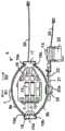
图1示出设置有座垫的轮椅,在所述坐垫中包含根据本发明的支撑装置;Figure 1 shows a wheelchair provided with a seat cushion in which a support device according to the invention is incorporated;
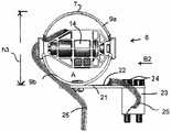
图2A和2B分别另外示出根据本发明的支撑装置的从斜上方观看的等距视图以及它的侧视图;Figures 2A and 2B additionally show an isometric view from obliquely above and a side view thereof, respectively, of a support device according to the invention;
图3A-F分别以不同的视图和不同的状态示出图2A和2B的支撑装置的支撑元件的三个视图;Figures 3A-F show three views of the support element of the support device of Figures 2A and 2B in different views and in different states, respectively;
图4示出替代实施例中的支撑元件的弯曲板的示意图;以及Figure 4 shows a schematic view of a curved plate of a support element in an alternative embodiment; and
图5示出根据本发明的支撑装置的使用者过程的示例的流程图。Fig. 5 shows a flowchart of an example of a user procedure of a support device according to the invention.
具体实施方式Detailed ways
图1中的轮椅1为根据本发明的支撑装置的应用示例。根据本发明所述的支撑装置可以在需要在椅子和床上以坐位或斜靠位支撑人的任何情况下被使用。The wheelchair 1 in Fig. 1 is an application example of the support device according to the present invention. The support device according to the invention can be used in any situation where a person needs to be supported in a sitting or reclining position on chairs and beds.
轮椅1包括由轮支撑的框架2,在所述框架2上布置有靠背3和座4。在座4上放置有垫5,在垫5中包含根据本发明的支撑装置10的示例。The wheelchair 1 comprises a
在图2A和2B中更详细地示出支撑装置10。支撑装置10包括以多个系列定位的一组支撑元件6,其中相继的系列沿着支撑元件6的长度的一半相对于彼此移位。所述一组支撑元件周围被由合成泡沫制成的带8包围,其中仅仅示出所述带8的两个侧。支撑元件6附接至刚性底板40,包含连接件42的印刷电路板41略微高于刚性底板40也位于所述刚性底板40上。支撑元件6在它们的顶侧处各自形成子支撑表面7,其中子支撑表面7被泡沫橡胶层30覆盖并且整体被包裹物31(其形成主支撑表面)包围,参见图2B。主支撑表面和泡沫橡胶层被支撑于子支撑表面上。支撑装置设置有可编程的控制单元100,所述可编程的控制单元100设置有电源,比如电池。The
在图3A-C中更详细地示出支撑元件6。支撑元件6包括两个可弹性地弯曲的弯曲板9a、9b,所述弯曲板9a、9b分别以凸形形式向上和向下弯曲。弯曲板9a、b可以由比如尼龙的合成材料制成。在弯曲板9a、b的凹面侧之间形成空间A,在所述空间中容置有电动机、在所述示例中步进电动机14。步进电动机14(其经由配线26连接至印刷电路板41上的连接件42并且经由印刷电路板41连接至控制单元100)附接至切开的壳体16,并且沿水平方向B1、B2驱动轴15。轴15的端部15a附接于端块18中,弯曲板9a的珠状边缘形端部19a和弯曲板9b的珠状边缘形端部19b通过所述端块18连接,以便在竖直平面中铰接。弯曲板9a和9b的另外的端部类似地连接至与壳体16成一体的端块17。The
在它的中心中,最下部的弯曲板9b(沿纵向方向和宽度方向两者考虑)在扁平梁21的自由端附近通过螺栓连接件20附接,所述扁平梁21在一侧上被夹紧,所述梁在竖直平面中可弹性地弯曲。在另一个端部处,梁21通过螺钉24以刚性夹紧的方式附接至支撑块23,所述支撑块刚性地附接至刚性板40。In its center, the lowermost
螺栓连接件20具有向下延伸的头部20a,所述头部20a位于止动件(未示出)上方,所述止动件附接至板40并且从其向上延伸。该止动件限制梁21的自由端的向下的移动。The bolted
电阻应变仪22布置于梁21上,所述应变仪经由配线25连接至印刷电路板41上的连接件42,并且经由印刷电路板41连接至控制单元100。A
在图3D-F中,示出可以如何通过由控制单元100操作支撑元件6来分别地影响弯曲板9a和弯曲板9b的顶部与底部之间的竖直距离。在图3D中,轴15沿方向B2完全地缩回至步进电动机14中。支撑元件6的高度h3因此达到它的最大值。当步进电动机14使轴15延伸(方向B1)时,端块17与18之间的水平距离将增大,结果,支撑元件6的高度h2减小,参见图3E。当轴15已经延伸至它的最大限度时,如图3F所示,高度h1达到它的最小值。当轴15缩回(方向B2)时,高度将再次增大。In FIGS. 3D-F it is shown how the vertical distance between the top and the bottom of the
图4示出弯曲板9a的实施例,其中子支撑表面7由小平板50形成,所述小平板50在底侧处设置有轴承滚珠51,所述轴承滚珠被容置成可在与弯曲板9a一体地形成的轴承腔52中沿方向C旋转。Figure 4 shows an embodiment of a
在实践中,一旦使用者已经离开例如放置于图1的轮椅上的支撑装置,并且支撑装置因此未被加负载,控制单元100就将控制所有支撑元件6的步进电动机14以进入轴15的缩回位置。在控制单元中,将电阻应变仪22的相关状态存储为零位。然后对支撑装置进行校准或“调零”,还参见图5中的图表。也可以通过使所有的轴完全地伸出而进行调零或校准。控制单元100随后将控制步进电动机14来使轴15伸出至伸长长度的一半。然后支撑装置可供使用。In practice, the
当使用者坐在支撑表面上时,由使用者的身体在一个支撑元件6上所施加的力将大于在另一个支撑元件上所施加的力。一些支撑元件、特别地在支撑装置的边缘处的那些支撑元件将不会被加负载。When the user sits on the support surface, the force exerted by the user's body on one
支撑元件6上的负载将导致相应的梁21弯曲,从而引起附接至它的电阻应变仪22的状态的改变。在控制单元100中检测到该改变,所述控制单元100通过使用电阻应变仪的数据来计算施加于梁21上的力。对于所有被加负载的支撑元件都进行这一步。控制单元100随后计算那些力的算术平均值。The load on the
在控制单元100中,然后将针对每个被加负载的支撑元件计算的力F1、F2、…、Fn与所计算出的平均力Fmean(在图中被称为Fm)进行比较。如果结果是支撑元件上的力超过Fmean,则控制用于该支撑元件的步进电动机以使轴伸出一步、例如2毫米。结果,两个弯曲板9a、b的凸度将减小,结果该支撑元件6的子支撑表面7将变得更低。如果结果是支撑元件上的力小于Fmean,则控制用于该支撑元件的步进电动机以使轴缩回一步。结果,两个弯曲板9a、b的凸度将增大,结果该支撑元件6的子支撑表面7将变得更高。在随后被调节得更低的子支撑表面上,使用者所施加的力将变得更小,并且在被调节得更高的子支撑表面上,力的确将增大。在该测量和计算步骤以及调节步骤之后,反复不断地重复所述过程直至F1、F2、…、Fn大致等于Fmean。In the
随后,在使用者处于支撑装置上的情况下,连续地执行所述步骤,以使得可以保持使用者的姿势的改变而没有不利影响。Subsequently, with the user on the support device, the steps are carried out continuously, so that changes in the user's posture can be maintained without adverse effects.
在将所计算出的力F1、F2、…、Fn与Fmean进行比较的步骤之后控制支撑元件6的电动机14在一个实施例中可以成组进行,比如,首先操作第一组相邻的支撑元件中的所期望的支撑元件,随后操作第二组中的所期望的支撑元件,等等。这可以快速地相继地进行。可以保持所需的功率有限,这在将电池用于电动机的电源时是有利的。Controlling the
一个或多个发明根本不限于说明书中所描述的以及附图中所示出的实施例。包含以上描述是为了示例说明本发明的优选实施例的操作而不是为了限制本发明的范围。从以上解释说明开始,落入本发明的精神和范围内的许多变化对于本领域技术人员而言将是显而易见的。说明书中所描述的以及附图中所示出的部件的变化是可能的。它们在一个或多个发明的其它实施例中可以被单独地使用。给出的各个示例的部分可以组合在一起。The invention or inventions are not at all limited to the embodiments described in the description and shown in the drawings. The above description is included to illustrate the operation of the preferred embodiment of the invention and not to limit the scope of the invention. From the above explanations, many variations that fall within the spirit and scope of the invention will be apparent to those skilled in the art. Variations are possible in the components described in the specification and shown in the drawings. They may be used individually in other embodiments of one or more inventions. Portions of various examples given may be combined together.
Claims (51)
Applications Claiming Priority (3)
| Application Number | Priority Date | Filing Date | Title |
|---|---|---|---|
| NL2021000 | 2018-05-29 | ||
| NL2021000ANL2021000B1 (en) | 2018-05-29 | 2018-05-29 | Device for supporting people |
| PCT/NL2019/050305WO2019231317A1 (en) | 2018-05-29 | 2019-05-28 | Device for supporting a person |
Publications (2)
| Publication Number | Publication Date |
|---|---|
| CN112888411A CN112888411A (en) | 2021-06-01 |
| CN112888411Btrue CN112888411B (en) | 2023-03-21 |
Family
ID=63684383
Family Applications (1)
| Application Number | Title | Priority Date | Filing Date |
|---|---|---|---|
| CN201980050317.7AActiveCN112888411B (en) | 2018-05-29 | 2019-05-28 | Device for supporting a person |
Country Status (5)
| Country | Link |
|---|---|
| US (2) | US11786422B2 (en) |
| EP (1) | EP3801430B1 (en) |
| CN (1) | CN112888411B (en) |
| NL (1) | NL2021000B1 (en) |
| WO (1) | WO2019231317A1 (en) |
Family Cites Families (31)
| Publication number | Priority date | Publication date | Assignee | Title |
|---|---|---|---|---|
| GB1377738A (en) | 1971-07-31 | 1974-12-18 | Avery Ltd W T | Force measuring devices |
| US6392550B1 (en)* | 2000-11-17 | 2002-05-21 | Ford Global Technologies, Inc. | Method and apparatus for monitoring driver alertness |
| US20030109817A1 (en)* | 2001-12-11 | 2003-06-12 | Shimon Berl | Supplementary knee support brace |
| US6880886B2 (en) | 2002-09-12 | 2005-04-19 | Steelcase Development Corporation | Combined tension and back stop function for seating unit |
| US10512575B2 (en)* | 2007-02-06 | 2019-12-24 | Deka Products Limited Partnership | Dynamic support apparatus |
| JP4254295B2 (en)* | 2003-03-25 | 2009-04-15 | アイシン精機株式会社 | Seating detection device |
| NL1028539C2 (en)* | 2005-03-14 | 2006-09-18 | Hans Voorwinde Beheer B V | Device for preventing pressure ulcers. |
| DE202006003948U1 (en)* | 2006-03-14 | 2006-07-06 | Achilles, Hans-Jürgen | Therapeutic cushion for person suffering from tetraplegia, comprising pressure regulating system with pressure sensor |
| DE102007053119A1 (en)* | 2007-11-08 | 2009-05-14 | Bayerische Motoren Werke Aktiengesellschaft | Method and device for adjusting a seat and seat |
| WO2010044843A1 (en)* | 2008-10-13 | 2010-04-22 | George Papaioannou | Adaptable surface for use in beds and chairs to reduce occurrence of pressure ulcers |
| JP5167409B2 (en)* | 2010-01-27 | 2013-03-21 | 東海ゴム工業株式会社 | Postural pressure control device |
| DE102012201331A1 (en)* | 2011-03-02 | 2012-09-06 | Ford Global Technologies, Llc | Seat, in particular vehicle seat, with a deformation element and method for driving a deformation element of a seat |
| EP2783602B1 (en)* | 2011-11-21 | 2017-06-28 | Paramount Bed Co., Ltd. | Mattress, pressure sensor calibration method, and bed device |
| US20140366277A1 (en) | 2012-01-26 | 2014-12-18 | Huntleigh Technology Limited | Pressure measurement systems and methods with moisture vapor control |
| EP2790550B1 (en) | 2012-01-31 | 2016-04-06 | Backjoy Orthotics, LLC | Seat cushion with flexible contouring |
| WO2013123119A1 (en)* | 2012-02-15 | 2013-08-22 | Stryker Corporation | Patient support apparatus and controls therefor |
| US9486160B2 (en)* | 2012-06-09 | 2016-11-08 | Xsensor Technology Corporation | Analysing seating using pressure sensors |
| WO2014084283A1 (en)* | 2012-11-28 | 2014-06-05 | テイ・エス テック株式会社 | Vehicle seat |
| CN105263367A (en) | 2013-06-06 | 2016-01-20 | 株式会社伊藤喜 | Chair |
| FR3013328B1 (en)* | 2013-11-20 | 2017-08-04 | Zodiac Seats France | SELF-ADJUSTABLE AIRCRAFT SEAT TO THE MORPHOLOGY OF A PASSENGER |
| US9955795B2 (en)* | 2014-06-05 | 2018-05-01 | Matthew W. Krenik | Automated bed and method of operation thereof |
| EP3616664B1 (en)* | 2014-07-28 | 2023-02-15 | DEKA Products Limited Partnership | Dynamic support apparatus |
| US10293718B1 (en)* | 2016-06-22 | 2019-05-21 | Apple Inc. | Motion control seating system |
| US10549662B2 (en)* | 2016-12-22 | 2020-02-04 | GM Global Technology Operations LLC | Climate control system and method for heating and cooling a seat of a vehicle based on an occupant pressure distribution, and a method of manufacturing a seat climate control system |
| US10974619B2 (en)* | 2017-03-28 | 2021-04-13 | Ts Tech Co., Ltd. | Vehicle seat and passenger selection system |
| US11089881B2 (en)* | 2017-12-15 | 2021-08-17 | Nanthealth, Inc. | Modular mattress and bedframe system with surface positioning actuators |
| US12042453B2 (en)* | 2019-02-26 | 2024-07-23 | Hill-Rom Services, Inc. | Patient positioning apparatus and mattress |
| WO2020232161A1 (en)* | 2019-05-14 | 2020-11-19 | Ige, Llc | Support system including layers of spacer fabric and non-viscoelastic pressure relief material, and method for measuring pressure and pressure distribution properties of a support system |
| AT523112A1 (en)* | 2019-10-16 | 2021-05-15 | Zenzmaier Cornelia | Method for determining the location and position of a person's pelvis |
| KR20220097625A (en)* | 2020-12-30 | 2022-07-08 | 서울대학교병원 | Smart Mattress |
| US20220212578A1 (en)* | 2021-01-04 | 2022-07-07 | Lars Roulund | Ergonomic seating system and method of use |
- 2018
- 2018-05-29NLNL2021000Apatent/NL2021000B1/enactive
- 2019
- 2019-05-28EPEP19743016.8Apatent/EP3801430B1/enactiveActive
- 2019-05-28USUS17/058,780patent/US11786422B2/enactiveActive
- 2019-05-28WOPCT/NL2019/050305patent/WO2019231317A1/ennot_activeCeased
- 2019-05-28CNCN201980050317.7Apatent/CN112888411B/enactiveActive
- 2023
- 2023-02-21USUS18/172,159patent/US12016805B2/enactiveActive
Also Published As
| Publication number | Publication date |
|---|---|
| WO2019231317A1 (en) | 2019-12-05 |
| EP3801430B1 (en) | 2025-05-21 |
| EP3801430C0 (en) | 2025-05-21 |
| US12016805B2 (en) | 2024-06-25 |
| CN112888411A (en) | 2021-06-01 |
| US11786422B2 (en) | 2023-10-17 |
| US20210137757A1 (en) | 2021-05-13 |
| NL2021000B1 (en) | 2019-12-04 |
| US20230190552A1 (en) | 2023-06-22 |
| EP3801430A1 (en) | 2021-04-14 |
Similar Documents
| Publication | Publication Date | Title |
|---|---|---|
| CA2179590C (en) | Apparatus for positioning a human body | |
| US5642302A (en) | Method and apparatus for positioning a human body | |
| CA2743455C (en) | Pivotable seat | |
| US6425153B1 (en) | Support cushion | |
| US8048005B2 (en) | Hospital bed control apparatus | |
| JP7580395B2 (en) | Body Positioning Device | |
| CN1047967A (en) | The ventilating control of inflation supporter | |
| US12161592B2 (en) | Articulating chair | |
| CN112888411B (en) | Device for supporting a person | |
| JP3906993B2 (en) | Sitting posture evaluation device and sitting posture holding device for persons with disabilities | |
| CN108158279B (en) | A dynamically adjustable pad and teen seat equipped with the same | |
| JP4889877B2 (en) | Chair | |
| US20250031867A1 (en) | Chairs | |
| RU2808811C2 (en) | Device for positioning user's body and method for controlling this device |
Legal Events
| Date | Code | Title | Description |
|---|---|---|---|
| PB01 | Publication | ||
| PB01 | Publication | ||
| SE01 | Entry into force of request for substantive examination | ||
| SE01 | Entry into force of request for substantive examination | ||
| GR01 | Patent grant | ||
| GR01 | Patent grant | ||
| CP01 | Change in the name or title of a patent holder | Address after:Holland Pa Bond Ray Hurt Patentee after:Hansworth Windby Hill LLC Patentee after:DINK 7 charm Co.,Ltd. Address before:Holland Pa Bond Ray Hurt Patentee before:Hans wowende Co.,Ltd. Patentee before:DINK 7 charm Co.,Ltd. | |
| CP01 | Change in the name or title of a patent holder |