CN112887521B - Camera modules and electronic equipment - Google Patents
Camera modules and electronic equipmentDownload PDFInfo
- Publication number
- CN112887521B CN112887521BCN201911209202.6ACN201911209202ACN112887521BCN 112887521 BCN112887521 BCN 112887521BCN 201911209202 ACN201911209202 ACN 201911209202ACN 112887521 BCN112887521 BCN 112887521B
- Authority
- CN
- China
- Prior art keywords
- motor
- sma
- lens
- camera module
- fixed
- Prior art date
- Legal status (The legal status is an assumption and is not a legal conclusion. Google has not performed a legal analysis and makes no representation as to the accuracy of the status listed.)
- Active
Links
Images


Classifications
- H—ELECTRICITY
- H04—ELECTRIC COMMUNICATION TECHNIQUE
- H04M—TELEPHONIC COMMUNICATION
- H04M1/00—Substation equipment, e.g. for use by subscribers
- H04M1/02—Constructional features of telephone sets
- H04M1/0202—Portable telephone sets, e.g. cordless phones, mobile phones or bar type handsets
- H04M1/026—Details of the structure or mounting of specific components
- H04M1/0264—Details of the structure or mounting of specific components for a camera module assembly
- H—ELECTRICITY
- H04—ELECTRIC COMMUNICATION TECHNIQUE
- H04N—PICTORIAL COMMUNICATION, e.g. TELEVISION
- H04N23/00—Cameras or camera modules comprising electronic image sensors; Control thereof
- H04N23/50—Constructional details
- H04N23/55—Optical parts specially adapted for electronic image sensors; Mounting thereof
- H—ELECTRICITY
- H04—ELECTRIC COMMUNICATION TECHNIQUE
- H04N—PICTORIAL COMMUNICATION, e.g. TELEVISION
- H04N23/00—Cameras or camera modules comprising electronic image sensors; Control thereof
- H04N23/50—Constructional details
- G—PHYSICS
- G03—PHOTOGRAPHY; CINEMATOGRAPHY; ANALOGOUS TECHNIQUES USING WAVES OTHER THAN OPTICAL WAVES; ELECTROGRAPHY; HOLOGRAPHY
- G03B—APPARATUS OR ARRANGEMENTS FOR TAKING PHOTOGRAPHS OR FOR PROJECTING OR VIEWING THEM; APPARATUS OR ARRANGEMENTS EMPLOYING ANALOGOUS TECHNIQUES USING WAVES OTHER THAN OPTICAL WAVES; ACCESSORIES THEREFOR
- G03B13/00—Viewfinders; Focusing aids for cameras; Means for focusing for cameras; Autofocus systems for cameras
- G03B13/32—Means for focusing
- G03B13/34—Power focusing
- G03B13/36—Autofocus systems
- G—PHYSICS
- G03—PHOTOGRAPHY; CINEMATOGRAPHY; ANALOGOUS TECHNIQUES USING WAVES OTHER THAN OPTICAL WAVES; ELECTROGRAPHY; HOLOGRAPHY
- G03B—APPARATUS OR ARRANGEMENTS FOR TAKING PHOTOGRAPHS OR FOR PROJECTING OR VIEWING THEM; APPARATUS OR ARRANGEMENTS EMPLOYING ANALOGOUS TECHNIQUES USING WAVES OTHER THAN OPTICAL WAVES; ACCESSORIES THEREFOR
- G03B30/00—Camera modules comprising integrated lens units and imaging units, specially adapted for being embedded in other devices, e.g. mobile phones or vehicles
- H—ELECTRICITY
- H02—GENERATION; CONVERSION OR DISTRIBUTION OF ELECTRIC POWER
- H02K—DYNAMO-ELECTRIC MACHINES
- H02K41/00—Propulsion systems in which a rigid body is moved along a path due to dynamo-electric interaction between the body and a magnetic field travelling along the path
- H02K41/02—Linear motors; Sectional motors
- H02K41/035—DC motors; Unipolar motors
- H02K41/0352—Unipolar motors
- H02K41/0354—Lorentz force motors, e.g. voice coil motors
- H—ELECTRICITY
- H04—ELECTRIC COMMUNICATION TECHNIQUE
- H04M—TELEPHONIC COMMUNICATION
- H04M1/00—Substation equipment, e.g. for use by subscribers
- H04M1/02—Constructional features of telephone sets
- H04M1/0202—Portable telephone sets, e.g. cordless phones, mobile phones or bar type handsets
- H04M1/026—Details of the structure or mounting of specific components
- H04M1/0262—Details of the structure or mounting of specific components for a battery compartment
- H—ELECTRICITY
- H04—ELECTRIC COMMUNICATION TECHNIQUE
- H04M—TELEPHONIC COMMUNICATION
- H04M1/00—Substation equipment, e.g. for use by subscribers
- H04M1/02—Constructional features of telephone sets
- H04M1/0202—Portable telephone sets, e.g. cordless phones, mobile phones or bar type handsets
- H04M1/026—Details of the structure or mounting of specific components
- H04M1/0266—Details of the structure or mounting of specific components for a display module assembly
- H—ELECTRICITY
- H04—ELECTRIC COMMUNICATION TECHNIQUE
- H04M—TELEPHONIC COMMUNICATION
- H04M1/00—Substation equipment, e.g. for use by subscribers
- H04M1/02—Constructional features of telephone sets
- H04M1/0202—Portable telephone sets, e.g. cordless phones, mobile phones or bar type handsets
- H04M1/026—Details of the structure or mounting of specific components
- H04M1/0277—Details of the structure or mounting of specific components for a printed circuit board assembly
- H—ELECTRICITY
- H04—ELECTRIC COMMUNICATION TECHNIQUE
- H04N—PICTORIAL COMMUNICATION, e.g. TELEVISION
- H04N23/00—Cameras or camera modules comprising electronic image sensors; Control thereof
- H04N23/50—Constructional details
- H04N23/54—Mounting of pick-up tubes, electronic image sensors, deviation or focusing coils
- H—ELECTRICITY
- H04—ELECTRIC COMMUNICATION TECHNIQUE
- H04N—PICTORIAL COMMUNICATION, e.g. TELEVISION
- H04N23/00—Cameras or camera modules comprising electronic image sensors; Control thereof
- H04N23/57—Mechanical or electrical details of cameras or camera modules specially adapted for being embedded in other devices
- H—ELECTRICITY
- H04—ELECTRIC COMMUNICATION TECHNIQUE
- H04N—PICTORIAL COMMUNICATION, e.g. TELEVISION
- H04N23/00—Cameras or camera modules comprising electronic image sensors; Control thereof
- H04N23/58—Means for changing the camera field of view without moving the camera body, e.g. nutating or panning of optics or image sensors
- H—ELECTRICITY
- H04—ELECTRIC COMMUNICATION TECHNIQUE
- H04N—PICTORIAL COMMUNICATION, e.g. TELEVISION
- H04N23/00—Cameras or camera modules comprising electronic image sensors; Control thereof
- H04N23/60—Control of cameras or camera modules
- H04N23/68—Control of cameras or camera modules for stable pick-up of the scene, e.g. compensating for camera body vibrations
- H04N23/682—Vibration or motion blur correction
- H04N23/685—Vibration or motion blur correction performed by mechanical compensation
- H04N23/687—Vibration or motion blur correction performed by mechanical compensation by shifting the lens or sensor position
- G—PHYSICS
- G03—PHOTOGRAPHY; CINEMATOGRAPHY; ANALOGOUS TECHNIQUES USING WAVES OTHER THAN OPTICAL WAVES; ELECTROGRAPHY; HOLOGRAPHY
- G03B—APPARATUS OR ARRANGEMENTS FOR TAKING PHOTOGRAPHS OR FOR PROJECTING OR VIEWING THEM; APPARATUS OR ARRANGEMENTS EMPLOYING ANALOGOUS TECHNIQUES USING WAVES OTHER THAN OPTICAL WAVES; ACCESSORIES THEREFOR
- G03B2205/00—Adjustment of optical system relative to image or object surface other than for focusing
- G03B2205/0053—Driving means for the movement of one or more optical element
- G03B2205/0076—Driving means for the movement of one or more optical element using shape memory alloys
Landscapes
- Engineering & Computer Science (AREA)
- Signal Processing (AREA)
- Multimedia (AREA)
- Physics & Mathematics (AREA)
- General Physics & Mathematics (AREA)
- Chemical & Material Sciences (AREA)
- Combustion & Propulsion (AREA)
- Electromagnetism (AREA)
- Power Engineering (AREA)
- Studio Devices (AREA)
- Adjustment Of Camera Lenses (AREA)
Abstract
Translated fromChinese
Description
Translated fromChinese技术领域technical field
本申请实施例涉及拍摄技术领域,尤其涉及一种摄像头模组及电子设备。The embodiments of the present application relate to the technical field of photography, and in particular, to a camera module and an electronic device.
背景技术Background technique
随着智能手机摄像头拍照功能的日趋强大,光学防抖(optical imagestabilizer,OIS)逐渐成为了手机摄像头的主要卖点与竞争力之一。光学防抖的作用是拍照时对一定频率和幅度范围内的手机抖动进行实时检测反馈并进行反向补偿,由于该补偿通常是通过光学镜头(lens)矫正光路得到的,较之用软件算法提升增益而言,画质上的损失非常小,因而很好地保证了图像质量。With the increasingly powerful camera functions of smart phone cameras, optical image stabilization (OIS) has gradually become one of the main selling points and competitiveness of mobile phone cameras. The function of optical image stabilization is to perform real-time detection and feedback of mobile phone shake within a certain frequency and amplitude range when taking pictures and perform reverse compensation. Because the compensation is usually obtained by correcting the optical path through an optical lens (lens), it is better than using software algorithms. In terms of gain, the loss in image quality is very small, so the image quality is well guaranteed.
目前常用的光学防抖马达主要是音圈马达(voice coil motor,VCM),音圈马达包括马达支架及位于马达支架内侧的载体和四对驱动组件,载体用于承载镜头,四对驱动组件分别位于载体的四周,每对驱动组件均包括磁铁和线圈,磁铁和线圈中的一者固定于载体、另一者固定于马达支架。通过控制四对驱动组件的线圈的电流通断及大小,使得载体带动镜头在垂直于镜头光轴的平面上移动,从而实现镜头移动(lens shift)方式的光学防抖。At present, the commonly used optical anti-shake motor is mainly a voice coil motor (VCM). The voice coil motor includes a motor bracket, a carrier located inside the motor bracket, and four pairs of driving components. The carrier is used to carry the lens, and the four pairs of driving components are respectively Located around the carrier, each pair of driving components includes a magnet and a coil, one of the magnets and the coil is fixed on the carrier, and the other is fixed on the motor bracket. By controlling the current on-off and the size of the coils of the four pairs of driving components, the carrier drives the lens to move on a plane perpendicular to the optical axis of the lens, thereby realizing the optical anti-shake method of lens shift.
由于音圈马达移动镜头时,音圈与磁铁之间的电磁力需要同时带动镜头、载体及固定于载体的四对音圈或四对磁铁移动,载重较大,导致音圈马达的防抖功耗较高。When the voice coil motor moves the lens, the electromagnetic force between the voice coil and the magnet needs to drive the lens, the carrier and the four pairs of voice coils or four pairs of magnets fixed on the carrier to move at the same time, and the load is large, resulting in the anti-shake function of the voice coil motor. Higher consumption.
发明内容SUMMARY OF THE INVENTION
本申请实施例的目的在于提供一种防抖功耗较低的摄像头模组及电子设备。The purpose of the embodiments of the present application is to provide a camera module and an electronic device with low anti-shake power consumption.
第一方面,本申请实施例提供一种摄像头模组。摄像头模组包括模组支架以及堆叠地安装于模组支架内侧的镜头、图像传感器和SMA马达,SMA马达位于镜头的出光侧,图像传感器位于镜头与SMA马达之间且固定于SMA马达,SMA马达用于驱动图像传感器在镜头的光轴的垂直平面上移动。In a first aspect, an embodiment of the present application provides a camera module. The camera module includes a module bracket and a lens, an image sensor and an SMA motor stacked on the inside of the module bracket. The SMA motor is located on the light-emitting side of the lens, and the image sensor is located between the lens and the SMA motor and is fixed to the SMA motor. The SMA motor Used to drive the image sensor to move in a plane perpendicular to the optical axis of the lens.
在本实施例中,由于图像传感器相较于镜头的重量大幅度降低,因此摄像头模组通过图像传感器平移方式实现防抖,能够降低SMA马达的驱动负载,使得SMA马达的功耗较小,故而摄像头模组的防抖功耗较低。In this embodiment, since the weight of the image sensor is greatly reduced compared with that of the lens, the camera module realizes anti-shake through the translation of the image sensor, which can reduce the driving load of the SMA motor, so that the power consumption of the SMA motor is small. The anti-shake power consumption of the camera module is low.
此外,由于镜头对光线的聚集作用,相较于传统的移动镜头进行防抖的方案,本实施例的摄像头模组通过SMA马达驱动图像传感器进行光路补偿所需要的补偿平移距离更短,因此进一步降低了SMA马达的功耗,使得摄像头模组的防抖功耗更低。换言之,在同等功耗下,本实施例的摄像头模组相较于传统方案具备更好的防抖性能。In addition, due to the focusing effect of the lens on light, compared with the traditional solution of moving the lens for anti-shake, the camera module of this embodiment uses the SMA motor to drive the image sensor to perform optical path compensation. The compensation translation distance required is shorter, so further The power consumption of the SMA motor is reduced, so that the anti-shake power consumption of the camera module is lower. In other words, under the same power consumption, the camera module of this embodiment has better anti-shake performance than the traditional solution.
可以理解的是,在本实施例中,在达到相同防抖性能的情况下,图像传感器的补偿平移距离相较于传统的镜头的补偿平移距离的下降幅度与镜头的镜片结构相关。可以通过优化镜头结构,获得期待的图像传感器的补偿平移距离范围,以使摄像头模组的性能更为理想,例如功耗更低、防抖反馈速度更快等。It can be understood that, in the present embodiment, under the condition of achieving the same anti-shake performance, the reduction of the compensation translation distance of the image sensor compared with that of the conventional lens is related to the lens structure of the lens. By optimizing the lens structure, the expected compensation translation distance range of the image sensor can be obtained, so that the performance of the camera module can be more ideal, such as lower power consumption and faster anti-shake feedback.
一种可选实施例中,SMA马达包括马达上部件、马达下部件、多个支座以及四根SMA线。图像传感器固定于马达上部件。马达下部件位于马达上部件远离图像传感器的一侧。多个支座位于马达下部件与马达上部件之间,多个支座的一端固定连接马达下部件,多个支座的另一端滑动连接马达上部件。各SMA线的一端固定于马达上部件、另一端固定于马达下部件,SMA线通电加热时产生收缩。In an alternative embodiment, the SMA motor includes an upper motor part, a lower motor part, a plurality of supports, and four SMA wires. The image sensor is fixed to the upper part of the motor. The lower part of the motor is located on the side of the upper part of the motor away from the image sensor. The plurality of supports are located between the lower part of the motor and the upper part of the motor, one end of the plurality of supports is fixedly connected to the lower part of the motor, and the other end of the plurality of supports is slidably connected to the upper part of the motor. One end of each SMA wire is fixed to the upper part of the motor, and the other end is fixed to the lower part of the motor, and the SMA wire shrinks when it is heated by electricity.
在本实施例中,SMA线通电时,通电产生的热量使得SMA线的温度上高,实现由低温马氏体相逆相变为高温奥氏体相,恢复到变性前记忆,从而使SMA线产生收缩。由于SMA线的收缩导致的长度变化,实质上是由于材料晶相结构转换时产生的,即马氏体与奥氏体之间的转换。而这种因晶体结构变化(即原子与原子之间的间隙变换)的微观粒子之间的引力,使得宏观SMA线收缩时的拉力较一般磁铁线圈间的电磁力大很多,因此SMA线的收缩可以驱动更重的负载,即可以实现大载重,故而SMA马达能够以较小的尺寸实现较大的驱动力。In this embodiment, when the SMA wire is energized, the heat generated by the energization increases the temperature of the SMA wire, realizing the reverse phase from the low temperature martensite phase to the high temperature austenite phase, and returning to the memory before the denaturation, so that the SMA wire is produce shrinkage. The length change caused by the shrinkage of the SMA wire is essentially due to the transformation of the crystal phase structure of the material, that is, the transformation between martensite and austenite. And this kind of attraction between microscopic particles due to the change of crystal structure (that is, the change of the gap between atoms and atoms) makes the pulling force of the macroscopic SMA wire when shrinking is much larger than the electromagnetic force between the general magnet coils, so the shrinkage of the SMA wire is much larger. A heavier load can be driven, that is, a large load can be realized, so the SMA motor can achieve a large driving force with a smaller size.
在本实施例中,由于SMA线通电加热时产生收缩,会对马达上部件产生对应的拉力,因此摄像头模组可以通过控制四根SMA线的电信号,使四根SMA对马达上部件施加的合力朝向预期方向,从而驱动马达上部件携带图像传感器向预期的方向和位置移动,使得摄像头模组能够通过平移图像传感器实现防抖。In this embodiment, since the SMA wire shrinks when it is energized and heated, a corresponding pulling force will be generated on the upper part of the motor. Therefore, the camera module can control the electrical signals of the four SMA wires, so that the four SMA wires exert a force on the upper part of the motor. The resultant force is directed towards the expected direction, so that the upper part of the drive motor carries the image sensor to move to the expected direction and position, so that the camera module can achieve anti-shake by translating the image sensor.
此外,相较于传统的防抖马达(也即音圈马达),SMA马达采用线材驱动方式、而非磁场驱动方式,SMA马达的结构更为精简,有助于摄像头模组的小型化,并且可以降低摄像头模组对周边环境产生的磁干扰。In addition, compared with the traditional anti-shake motor (that is, the voice coil motor), the SMA motor adopts a wire drive method instead of a magnetic field drive method. The structure of the SMA motor is more streamlined, which is conducive to the miniaturization of the camera module, and The magnetic interference of the camera module to the surrounding environment can be reduced.
马达上部件作为承载图像传感器的载体,只需要实现承载作用及简单的电连接关系,因此马达上部件的结构相较于传统的防抖马达的载体更为简单,马达上部件更易实现小型化、轻质化,使得SMA马达的负载小,摄像头模组的防抖功耗低。As the carrier of the image sensor, the upper part of the motor only needs to realize the bearing function and simple electrical connection relationship. Therefore, the structure of the upper part of the motor is simpler than that of the carrier of the traditional anti-shake motor, and the upper part of the motor is easier to achieve miniaturization, Lightweight, the load of the SMA motor is small, and the anti-shake power consumption of the camera module is low.
一些可选实施例中,四根SMA线两两成对,两对SMA线相对第一基准面对称设置,同一对的两根SMA线相对第二基准面对称设置,第一基准面及第二基准面均经过镜头的光轴。In some optional embodiments, the four SMA wires are paired in pairs, the two pairs of SMA wires are arranged symmetrically with respect to the first reference plane, the two SMA wires of the same pair are arranged symmetrically with respect to the second reference plane, the first reference plane and The second reference plane passes through the optical axis of the lens.
在本实施例中,通过限定四根SMA线的位置关系,使得摄像头模组可以通过控制四根SMA线内的电信号,使得四根SMA线对马达上部件的合力沿第一基准面移动或者沿第二基准面移动,并且可以通过在第一基准面上的位移和在第二基准面上的位移的合成位移,使得马达上部件携带图像传感器移动至摄像头模组的XY平面(也即镜头的光轴的垂直平面)的任意位置,从而实现图像传感器平移式防抖。In this embodiment, by defining the positional relationship of the four SMA wires, the camera module can control the electrical signals in the four SMA wires, so that the resultant force of the four SMA wires on the components on the motor moves along the first reference plane or It moves along the second reference plane, and can make the upper part of the motor carry the image sensor to move to the XY plane of the camera module (that is, the lens) through the combined displacement of the displacement on the first reference plane and the displacement on the second reference plane. Any position of the vertical plane of the optical axis), so as to realize the image sensor translation anti-shake.
一种可选实施例中,马达上部件包括第一侧面和第二侧面,第一侧面与第二侧面相对第二基准面对称设置。马达下部件包括正对马达上部件的中间区域以及围绕中间区域设置的边缘区域,多个支座固定于中间区域,边缘区域包括第一边缘区和第四边缘区,第一边缘区与第四边缘区相对第一基准面对称设置,第一边缘区与第一侧面对应设置。In an optional embodiment, the motor upper part includes a first side surface and a second side surface, and the first side surface and the second side surface are symmetrically arranged with respect to the second reference plane. The lower part of the motor includes a middle area facing the upper part of the motor and an edge area arranged around the middle area, a plurality of supports are fixed on the middle area, the edge area includes a first edge area and a fourth edge area, the first edge area and the fourth edge area are The edge area is symmetrically arranged with respect to the first reference plane, and the first edge area is arranged corresponding to the first side surface.
四根SMA线包括第一SMA线、第二SMA线、第三SMA线以及第四SMA线。第一SMA线的一端固定于马达上部件的第一侧面靠近第二侧面的一端,第一SMA线的另一端固定于马达下部件的第一边缘区靠近第四边缘区的一端。第二SMA线与第一SMA线相对第二基准面对称设置。第三SMA线与第二SMA线相对第一基准面对称设置。第四SMA线与第三SMA线相对第二基准面对称设置。The four SMA wires include a first SMA wire, a second SMA wire, a third SMA wire, and a fourth SMA wire. One end of the first SMA wire is fixed to one end of the first side of the motor upper part close to the second side, and the other end of the first SMA wire is fixed to one end of the first edge area of the motor lower part close to the fourth edge area. The second SMA wire and the first SMA wire are arranged symmetrically with respect to the second reference plane. The third SMA wire and the second SMA wire are arranged symmetrically with respect to the first reference plane. The fourth SMA wire and the third SMA wire are arranged symmetrically with respect to the second reference plane.
在本实施例中,SMA线的一端固定于马达上部件的对角位置、另一端固定于马达下部件的对角位置,使得SMA线能够在SMA马达内部空间有限的情况下具有较为足够的长度,从而具有足够的伸缩量,SMA马达能够具有更大的驱动行程区间,使得摄像头模组的防抖性能更佳。In this embodiment, one end of the SMA wire is fixed at the diagonal position of the upper part of the motor, and the other end is fixed at the diagonal position of the lower part of the motor, so that the SMA wire can have a relatively sufficient length under the condition that the internal space of the SMA motor is limited , so as to have enough expansion and contraction, the SMA motor can have a larger driving stroke range, so that the anti-shake performance of the camera module is better.
一种可选实施例中,SMA马达还包括两个弹簧臂,弹簧臂呈L形,弹簧臂均包括固定端部和活动端部,弹簧臂的活动端部固定于马达上部件,弹簧臂的固定端部固定于中间区域,两个弹簧臂中心对称设置,且对称中心为第一基准面与第二基准面的相交线。In an optional embodiment, the SMA motor further includes two spring arms, the spring arms are L-shaped, each of the spring arms includes a fixed end and a movable end, the movable end of the spring arm is fixed on the upper part of the motor, and the The fixed end is fixed in the middle area, the centers of the two spring arms are symmetrically arranged, and the symmetrical center is the intersection line of the first reference plane and the second reference plane.
在本实施例中,SMA马达通过设置弹簧臂,不仅能够在SMA线通电驱动马达上部件携带图像传感器移动的过程中,平衡和缓冲马达上部件的受力,使得马达上部件的移动更为平稳,而且能够在SMA线断电时,通过其在SMA线通电驱动马达上部件移动的过程中产生形变所形成的弹性力、驱动马达上部件携带图像传感器移回初始位置。In this embodiment, by setting the spring arm on the SMA motor, it can not only balance and buffer the force on the upper part of the motor when the SMA wire is energized to drive the upper part of the motor to move with the image sensor, so that the movement of the upper part of the motor is more stable , and when the SMA wire is powered off, through the elastic force formed by the deformation when the SMA wire is energized to drive the upper part of the motor to move, the upper part of the driving motor carries the image sensor and moves back to the initial position.
此外,由于弹簧臂的固定端部固定于马达下部件的中间区域,因此弹簧臂的活动空间与SMA线的活动空间错开,从而可以避免弹簧臂和SMA线在马达上部件的移动过程中发生干涉。In addition, since the fixed end of the spring arm is fixed to the middle area of the lower part of the motor, the movable space of the spring arm is staggered from the movable space of the SMA wire, so that the interference between the spring arm and the SMA wire during the movement of the upper motor part can be avoided .
一种可选实施例中,弹簧臂包括第一枝节和连接第一枝节的第二枝节,在第一枝节远离第二枝节的一端和第二枝节远离第一枝节的一端中,一者为弹簧臂的活动端部、另一者为弹簧臂的固定端部。马达上部件还包括第四侧面,第四侧面与第一侧面相对第一基准面对称设置,两个弹簧臂中的其中一个弹簧臂的第一枝节平行于第一侧面,第二枝节平行于第四侧面。In an optional embodiment, the spring arm includes a first branch and a second branch connected to the first branch, and in an end of the first branch away from the second branch and an end of the second branch away from the first branch, One is the movable end of the spring arm, and the other is the fixed end of the spring arm. The motor upper part further includes a fourth side surface, the fourth side surface and the first side surface are symmetrically arranged relative to the first reference plane, the first branch of one of the two spring arms is parallel to the first side surface, and the second branch is parallel to the first side surface. on the fourth side.
在本实施例中,两个弹簧臂的形状及位置与马达上部件相适配,故而两个弹簧臂对马达上部件的平衡和缓冲效果更佳。In this embodiment, the shapes and positions of the two spring arms are adapted to the upper part of the motor, so the balance and buffering effect of the two spring arms on the upper part of the motor are better.
一些实施例中,马达上部件的周侧面部分凹陷形成两个L形的避让槽。各避让槽均自马达上部件的一个侧面延伸至另一个侧面。两个弹簧臂分别对应两个避让槽设置。弹簧臂的活动端部固定于避让槽的槽侧壁,避让槽的槽侧壁连接马达上部件的周侧面。In some embodiments, the peripheral side part of the upper part of the motor is recessed to form two L-shaped escape grooves. Each avoidance groove extends from one side surface of the motor upper part to the other side surface. The two spring arms are respectively arranged corresponding to the two avoidance grooves. The movable end of the spring arm is fixed on the side wall of the groove of the avoidance groove, and the side wall of the groove of the avoidance groove is connected to the peripheral side surface of the upper part of the motor.
在本实施例中,SMA马达通过马达上部件的避让槽及避让槽下方的空间作为弹簧臂的安装空间及活动空间,使得弹簧臂与马达上部件的排布更为紧凑,SMA马达更易实现小型化。In this embodiment, the SMA motor uses the avoidance groove of the upper part of the motor and the space below the avoidance groove as the installation space and the movable space of the spring arm, so that the arrangement of the spring arm and the upper part of the motor is more compact, and the SMA motor is easier to realize small size change.
一种可选实施例中,SMA马达还包括四个弹簧臂,弹簧臂均包括固定端部和活动端部,弹簧臂的活动端部固定于马达上部件,弹簧臂的固定端部固定于中间区域,四个弹簧臂两两成对,两对弹簧臂相对第一基准面对称设置,同一对的两个弹簧臂相对第二基准面对称设置。In an optional embodiment, the SMA motor further includes four spring arms, each of which includes a fixed end and a movable end, the movable end of the spring arm is fixed on the upper part of the motor, and the fixed end of the spring arm is fixed in the middle. In the region, the four spring arms are paired in pairs, the two pairs of spring arms are symmetrically arranged relative to the first reference plane, and the two spring arms of the same pair are arranged symmetrically relative to the second reference plane.
在本实施例中,SMA马达通过设置弹簧臂,不仅能够在SMA线通电驱动马达上部件携带图像传感器移动的过程中,平衡和缓冲马达上部件的受力,使得马达上部件的移动更为平稳,而且能够在SMA线断电时,通过其在SMA线通电驱动马达上部件移动的过程中产生形变所形成的弹性力、驱动马达上部件携带图像传感器移回初始位置。此外,四个弹簧臂的排布关系与SMA线的排布关系相对应,因此四个弹簧臂能够更好地实现平衡作用和回复作用。In this embodiment, by setting the spring arm on the SMA motor, it can not only balance and buffer the force on the upper part of the motor when the SMA wire is energized to drive the upper part of the motor to move with the image sensor, so that the movement of the upper part of the motor is more stable , and when the SMA wire is powered off, through the elastic force formed by the deformation when the SMA wire is energized to drive the upper part of the motor to move, the upper part of the driving motor carries the image sensor and moves back to the initial position. In addition, the arrangement relationship of the four spring arms corresponds to the arrangement relationship of the SMA wires, so the four spring arms can better achieve balance and recovery.
此外,由于弹簧臂的固定端部固定于马达下部件的中间区域,因此弹簧臂的活动空间与SMA线的活动空间错开,从而可以避免弹簧臂和SMA线在马达上部件的移动过程中发生干涉。In addition, since the fixed end of the spring arm is fixed to the middle area of the lower part of the motor, the movable space of the spring arm is staggered from the movable space of the SMA wire, so that the interference between the spring arm and the SMA wire during the movement of the upper motor part can be avoided .
示例性的,四个弹簧臂可以分别平行于马达上部件的四个侧面。Exemplarily, the four spring arms may be respectively parallel to the four sides of the upper part of the motor.
一种可选实施例中,SMA马达还包括电路板,电路板位于马达下部件远离马达上部件的一侧,电路板固接模组支架,图像传感器通过多根键合线电连接电路板。In an optional embodiment, the SMA motor further includes a circuit board, the circuit board is located on the side of the lower part of the motor away from the upper part of the motor, the circuit board is fixed to the module bracket, and the image sensor is electrically connected to the circuit board through a plurality of bonding wires.
在本实施例中,键合线可以为金线或者其他。各键合线的长度较长。在图像传感器随马达上部件相对马达下部件平移时,图像传感器相对电路板平移,键合线随图像传感器的平移动作发生适应性变形,键合线较长时,更易实现形变,且线材不易发生断裂,使得键合线的可靠性较高,摄像头模组的使用寿命较长。In this embodiment, the bonding wires may be gold wires or others. The length of each bond wire is longer. When the image sensor translates relative to the lower part of the motor with the upper part of the motor, the image sensor translates relative to the circuit board, and the bonding wire is adaptively deformed with the translation of the image sensor. When the bonding wire is long, the deformation is easier to achieve, and the wire is not easy to occur. Broken, the reliability of the bonding wire is higher, and the service life of the camera module is longer.
一种可选实施例中,SMA马达还包括电路板,电路板位于马达下部件远离马达上部件的一侧,电路板固接模组支架。马达上部件设有第一导电件,支座设有第二导电件,马达下部件设有第三导电件及第四导电件。第三导电件电连接电路板与SMA线的一端,SMA线的另一端电连接第一导电件,第一导电件经第二导电件电连接第四导电件,第四导电件电连接电路板。In an optional embodiment, the SMA motor further includes a circuit board, the circuit board is located on the side of the lower part of the motor away from the upper part of the motor, and the circuit board is fixed to the module bracket. The upper part of the motor is provided with a first conductive part, the support is provided with a second conductive part, and the lower part of the motor is provided with a third conductive part and a fourth conductive part. The third conductive member is electrically connected to the circuit board and one end of the SMA wire, the other end of the SMA wire is electrically connected to the first conductive member, the first conductive member is electrically connected to the fourth conductive member through the second conductive member, and the fourth conductive member is electrically connected to the circuit board .
在本实施例中,电路板、第三导电件、SMA线、第一导电件、第二导电件以及第四导电件形成回路,电路板能够对SMA线供电,以通过电信号控制SMA线的收缩情况。In this embodiment, the circuit board, the third conductive member, the SMA wire, the first conductive member, the second conductive member, and the fourth conductive member form a loop, and the circuit board can supply power to the SMA wire, so as to control the SMA wire through electrical signals. shrinkage.
需要说明的是,摄像头模组通过对不同的SMA线输入不同的电信号,使不同的SMA线能够彼此独立地实现收缩。一些实施例中,不同SMA线对应的通路彼此独立。例如,第一导电件、第二导电件、第三导电件及第四导电件的数量均为四个,一个第三导电件、一根SMA线、一个第一导电件、一个第二导电件及一个第四导电件形成一个通路,SMA马达形成四个彼此独立的通路。另一些实施例中,不同SMA线对应的通路部分共用,以简化电路结构。例如:第三导电件的数量为四个,第一导电件、第二导电件及第四导电件的数量均为一个,四个第三导电件分别与四根SMA线的一端连接,四根SMA线的另一端均连接至第一导电件,第二导电件连接第一导电件及第四导电件。在本实施例中,不同的SMA线的通路具有不同的正极输入,共同相同的负极输出,不同的SMA线的通路仍可以输入不同的电信号。It should be noted that the camera module enables different SMA wires to shrink independently of each other by inputting different electrical signals to different SMA wires. In some embodiments, the paths corresponding to different SMA wires are independent of each other. For example, the number of the first conductive member, the second conductive member, the third conductive member and the fourth conductive member are all four, one third conductive member, one SMA wire, one first conductive member, and one second conductive member And a fourth conductive member forms a via, and the SMA motor forms four vias independent of each other. In other embodiments, the passage portions corresponding to different SMA wires are shared, so as to simplify the circuit structure. For example: the number of the third conductive members is four, the number of the first conductive member, the second conductive member and the fourth conductive member is one, and the four third conductive members are respectively connected to one end of the four SMA wires, and the four The other ends of the SMA wires are connected to the first conductive member, and the second conductive member is connected to the first conductive member and the fourth conductive member. In this embodiment, the paths of different SMA wires have different positive inputs and share the same negative output, and different electrical signals can still be input to the paths of different SMA wires.
其中,第一导电件、第二导电件、第三导电件及第四导电件均可以有多种实现结构,包括但不限于导线、导电贴片、导电结构件等。示例性的,第一导电件可以为马达上部件的电路的一部分,第三导电件及第四导电件可以为马达下部件的电路的一部分。第二导电件可以通过电镀方式形成,也可以通过粘接柔性电路板的方式形成,也可以通过嵌埋注塑成型埋设金属的方式形成。Wherein, the first conductive member, the second conductive member, the third conductive member and the fourth conductive member may have various implementation structures, including but not limited to wires, conductive patches, conductive structural members, and the like. Exemplarily, the first conductive member may be a part of the circuit of the upper part of the motor, and the third conductive member and the fourth conductive member may be part of the circuit of the lower part of the motor. The second conductive member may be formed by electroplating, or by bonding a flexible circuit board, or by embedding a metal in injection molding.
一些实施例中,摄像头模组还可以包括红外截止滤光片。红外截止滤光片安装于模组支架内侧且位于镜头与图像传感器之间。在摄像头模组的厚度方向Z上,红外截止滤光片与镜头及图像传感器彼此间隔地堆叠设置。红外截止滤光片用于过滤红外光,以提高摄像头模组的成像质量。示例性的,红外截止滤光片可以采用蓝玻璃。In some embodiments, the camera module may further include an infrared cut filter. The infrared cut-off filter is installed inside the module bracket and between the lens and the image sensor. In the thickness direction Z of the camera module, the infrared cut filter, the lens and the image sensor are stacked and arranged at intervals. The infrared cut filter is used to filter infrared light to improve the imaging quality of the camera module. Exemplarily, the infrared cut filter can be blue glass.
一种可选实施例中,镜头包括镜筒及固定于镜头内侧的至少一个镜片,镜筒固接模组支架。在本实施例中,由于镜筒固接模组支架,镜筒与模组支架的连接关系简单,因此有助于简化摄像头模组的结构,降低摄像头模组的成本,实现摄像头模组的小型化。In an optional embodiment, the lens includes a lens barrel and at least one lens fixed inside the lens, and the lens barrel is fixed to the module bracket. In this embodiment, since the lens barrel is fixed to the module bracket, the connection relationship between the lens barrel and the module bracket is simple, so it is helpful to simplify the structure of the camera module, reduce the cost of the camera module, and realize the miniaturization of the camera module. change.
在本实施例中,由于SMA马达驱动图像传感器在镜头的光轴的垂直平面上移动,图像传感器在镜头的光轴方向上与模组支架不发生相对移动,镜头相对模组支架固定,因此在镜头的光轴方向上,图像传感器与镜头之间的距离不变,镜头为定焦镜头,摄像头模组为防抖动的定焦模组。In this embodiment, since the SMA motor drives the image sensor to move on the vertical plane of the optical axis of the lens, the image sensor does not move relative to the module bracket in the optical axis direction of the lens, and the lens is fixed relative to the module bracket. In the direction of the optical axis of the lens, the distance between the image sensor and the lens remains unchanged, the lens is a fixed-focus lens, and the camera module is an anti-shake fixed-focus module.
一种可选实施例中,摄像头模组还包括音圈马达,音圈马达固定于模组支架内侧,镜头安装于音圈马达,音圈马达用于驱动镜头在镜头的光轴的平行方向上移动。In an optional embodiment, the camera module further includes a voice coil motor, the voice coil motor is fixed inside the module bracket, the lens is mounted on the voice coil motor, and the voice coil motor is used to drive the lens in the direction parallel to the optical axis of the lens. move.
在本实施例中,摄像头模组既可以通过SMA马达驱动图像传感器在镜头的光轴的垂直平面上平移,使得图像传感器与镜头的相对位置发生变化,以实现防抖;摄像头模组还可以通过音圈马达驱动镜头移动,使得镜头与图像传感器在镜头的光轴的平行方向上的距离发生变化,以实现自动对焦。换言之,摄像头模组具备自动对焦及光学防抖功能。In this embodiment, the camera module can drive the image sensor to translate on the vertical plane of the optical axis of the lens through the SMA motor, so that the relative position of the image sensor and the lens changes, so as to realize anti-shake; The voice coil motor drives the lens to move, so that the distance between the lens and the image sensor in the direction parallel to the optical axis of the lens changes, so as to realize automatic focusing. In other words, the camera module has auto focus and optical image stabilization functions.
一种可选实施例中,镜头包括镜筒及固定于镜头内侧的至少一个镜片。音圈马达包括马达支架、磁铁组件、音圈、上簧片及下簧片,马达支架位于模组支架内侧且固接模组支架,磁铁组件固定于马达支架内侧,镜头位于磁铁组件内侧,音圈位于镜筒与磁铁组件之间且固接镜筒,音圈通电时,带动镜头沿镜头的光轴的平行方向移动,上簧片的一侧固接镜筒的上端、另一侧固接马达支架,下簧片的一侧固接镜筒的下端、另一侧固接马达支架。In an optional embodiment, the lens includes a lens barrel and at least one lens fixed inside the lens. The voice coil motor includes a motor bracket, a magnet assembly, a voice coil, an upper reed and a lower reed. The motor bracket is located inside the module bracket and is fixed to the module bracket. The magnet assembly is fixed inside the motor bracket. The lens is located inside the magnet assembly. The coil is located between the lens barrel and the magnet assembly and is fixed to the lens barrel. When the voice coil is energized, it drives the lens to move in the parallel direction of the optical axis of the lens. One side of the upper spring is fixed to the upper end of the lens barrel, and the other side is fixed to For the motor bracket, one side of the lower spring is fixedly connected to the lower end of the lens barrel, and the other side is fixedly connected to the motor bracket.
一种可选实施例中,摄像头模组还包括棱镜,棱镜固定于模组支架的内侧、且位于镜头的入光侧,模组支架具有入光孔,入光孔正对棱镜设置。In an optional embodiment, the camera module further includes a prism, the prism is fixed on the inner side of the module bracket and located on the light incident side of the lens, the module bracket has a light entrance hole, and the light entrance hole is disposed facing the prism.
传统的潜望式的摄像头模组设有多组棱镜驱动马达,通过棱镜驱动马达驱动棱镜转动以实现防抖,结构复杂、难实现且可靠性差。本实施例摄像头模组通过SMA马达驱动图像传感器在镜头的光轴的垂直平面上移动、以实现光学防抖,故而相较于传统方案,本实施例摄像头模组省略能够棱镜驱动马达,将棱镜定于模组支架,从而在满足长焦防抖性能的前提下,简化模组结构、增加结构可靠性。The traditional periscope camera module is provided with multiple groups of prism drive motors, and the prism is driven to rotate by the prism drive motors to realize anti-shake, which is complicated in structure, difficult to realize and has poor reliability. The camera module of this embodiment drives the image sensor to move on the vertical plane of the optical axis of the lens through the SMA motor, so as to realize optical anti-shake. Therefore, compared with the traditional solution, the camera module of this embodiment omits the prism driving motor, and the prism It is fixed on the module bracket, so as to simplify the module structure and increase the structural reliability under the premise of satisfying the telephoto anti-shake performance.
第二方面,本申请实施例还提供一种电子设备。电子设备包括壳体、处理器及上述任一项的摄像头模组。处理器及摄像头模组收容于壳体,摄像头模组电连接处理器。电子设备应用摄像头模组进行拍摄时,功耗较低。In a second aspect, the embodiments of the present application further provide an electronic device. The electronic device includes a casing, a processor and any one of the above camera modules. The processor and the camera module are accommodated in the casing, and the camera module is electrically connected to the processor. When the electronic device uses the camera module for shooting, the power consumption is low.
附图说明Description of drawings
图1是本申请实施例提供的电子设备的结构示意图;1 is a schematic structural diagram of an electronic device provided by an embodiment of the present application;
图2是图1所示电子设备在另一角度的结构示意图;FIG. 2 is a schematic structural diagram of the electronic device shown in FIG. 1 at another angle;
图3是本申请实施例提供的摄像头模组在第一实施例中的结构示意图;3 is a schematic structural diagram of a camera module provided by an embodiment of the present application in the first embodiment;
图4A是图3所示摄像头模组处于抖动环境中的初始光路示意图;4A is a schematic diagram of the initial optical path of the camera module shown in FIG. 3 in a shaking environment;
图4B是图3所示摄像头模组实现光学防抖时的光路示意图;4B is a schematic diagram of the optical path when the camera module shown in FIG. 3 realizes optical image stabilization;
图5是图3所示摄像头模组的部分结构的俯视图;Fig. 5 is the top view of the partial structure of the camera module shown in Fig. 3;
图6是图5所示马达下部件的俯视图;Figure 6 is a top view of the lower part of the motor shown in Figure 5;
图7是图5所示SMA马达驱动图像传感器平移的结构示意图;FIG. 7 is a schematic structural diagram of the SMA motor driving the translation of the image sensor shown in FIG. 5;
图8是图3所示摄像头模组的部分结构示意图;Fig. 8 is a partial structural schematic diagram of the camera module shown in Fig. 3;
图9是图3所示摄像头模组的部分结构在另一些实施例中的俯视图;9 is a top view of a partial structure of the camera module shown in FIG. 3 in other embodiments;
图10是图9所示SMA马达的结构示意图;FIG. 10 is a schematic structural diagram of the SMA motor shown in FIG. 9;
图11是图9所示SMA马达在另一些实施例中的结构示意图;FIG. 11 is a schematic structural diagram of the SMA motor shown in FIG. 9 in other embodiments;
图12是图3所示摄像头模组的部分结构在再一些实施例中的俯视图;FIG. 12 is a top view of a part of the structure of the camera module shown in FIG. 3 in further embodiments;
图13是图12所示SMA马达的结构示意图;FIG. 13 is a schematic structural diagram of the SMA motor shown in FIG. 12;
图14是本申请实施例提供的摄像头模组在第二实施例中的结构示意图;14 is a schematic structural diagram of a camera module provided by an embodiment of the present application in a second embodiment;
图15是本申请实施例提供的摄像头模组在第三实施例中的结构示意图;15 is a schematic structural diagram of a camera module provided by an embodiment of the present application in a third embodiment;
图16是本申请实施例提供的摄像头模组在第四实施例中的结构示意图。FIG. 16 is a schematic structural diagram of the camera module provided by the embodiment of the present application in the fourth embodiment.
具体实施方式Detailed ways
下面结合本申请实施例中的附图对本申请以下各个实施例进行描述。The following embodiments of the present application will be described below with reference to the accompanying drawings in the embodiments of the present application.
本申请实施例提供一种摄像头模组和应用该摄像头模组的电子设备。摄像头模组采用形状记忆合金(shape memory alloy,SMA)马达驱动图像传感器在镜头的光轴的垂直平面上移动,通过图像传感器的平移实现光路偏移补偿,以使摄像头模组具有光学防抖功能。Embodiments of the present application provide a camera module and an electronic device using the camera module. The camera module uses a shape memory alloy (SMA) motor to drive the image sensor to move on the vertical plane of the optical axis of the lens, and realizes optical path offset compensation through the translation of the image sensor, so that the camera module has an optical anti-shake function. .
SMA马达包括马达上部件及连接马达上部件的多根SMA线,图像传感器固定于马达上部件,通过控制多根SMA线的电信号,驱动马达上部件携带图像传感器平移,因此SMA马达结构简单、体积小。由于SMA马达的驱动负载为重量较小的马达上部件和图像传感器,因此SMA马达的驱动负载较小,功耗较小。The SMA motor includes the upper part of the motor and a plurality of SMA wires connected to the upper part of the motor. The image sensor is fixed on the upper part of the motor. By controlling the electrical signals of the multiple SMA wires, the upper part of the motor is driven to carry the image sensor to translate, so the SMA motor has a simple structure, small volume. Since the driving load of the SMA motor is the lower motor upper part and the image sensor, the driving load of the SMA motor is small and the power consumption is small.
此外,由于镜头对光线的聚集作用,相较于传统的移动镜头进行防抖的方案,本实施例的摄像头模组的SMA马达驱动图像传感器进行光路补偿所需要的补偿平移距离(即行程)更短,进一步降低了SMA马达的功耗,故而摄像头模组的防抖功耗较低。In addition, due to the light-gathering effect of the lens, compared with the traditional solution of moving the lens for anti-shake, the SMA motor of the camera module of the present embodiment drives the image sensor to compensate for the translation distance (ie, stroke) required for optical path compensation. Short, further reduces the power consumption of the SMA motor, so the anti-shake power consumption of the camera module is low.
电子设备可以是手机、平板电脑、笔记本电脑、相机、可穿戴设备、电视等。其中,可穿戴设备可以是智能手环、智能手表、智能头显、智能眼镜等。Electronic devices can be cell phones, tablets, laptops, cameras, wearables, TVs, etc. Among them, the wearable device may be a smart bracelet, a smart watch, a smart head display, a smart glasses, and the like.
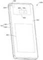
请一并参阅图1和图2,图1是本申请实施例提供的电子设备1000的结构示意图;图2是图1所示电子设备1000在另一角度的结构示意图。在本实施例中,以电子设备1000是手机为例进行说明。Please refer to FIG. 1 and FIG. 2 together. FIG. 1 is a schematic structural diagram of an
电子设备1000包括壳体100、显示屏200、前置摄像组件300、后置摄像组件400、主板500、处理器600、存储器700以及电池800。显示屏200用于显示图像,显示屏200还可以集成触摸功能。显示屏200安装于壳体100。壳体100可以包括边框1001和后盖1002。显示屏200和后盖1002分别安装于边框1001的相背两侧。在本实施例中,定义显示屏200朝向的空间为电子设备1000的前方,后盖1002朝向的空间电子设备1000的后方。The
一些实施例中,前置摄像组件300位于壳体100内侧且位于显示屏200下方。显示屏200设有透光部2001,前置摄像组件300经透光部2001采集电子设备1000前方的光线,以实现拍摄。前置摄像组件300可以包括后文实施例中描述的摄像头模组,也可以包括其他结构的摄像头模组。In some embodiments, the
一些实施例中,后盖1002设有至少一个摄像孔1003。后置摄像组件400位于壳体100内侧,后置摄像组件400经至少一个摄像孔1003采集电子设备1000后方的光线,以实现拍摄。本申请实施例中“至少一个”包括一个和多个两种情况。后置摄像组件400包括至少一个摄像头模组4001,例如可以包括标准摄像头模组、长焦摄像头模组、广角摄像头模组、超长焦摄像头模组、超广角摄像头模组中的一者或多者。示例性的,后置摄像组件400包括标准摄像头、广角摄像头及潜望式长焦摄像头。后置摄像组件400的摄像头模组4001可以包括后文实施例中描述的摄像头模组,也可以包括其他结构的摄像头模组。In some embodiments, the
一些实施例中,后置摄像组件400还可以包括闪光灯模组4002。后盖1002设有闪光灯孔1004,闪光灯模组4002位于壳体100内侧,经闪光灯孔1004射出光线。In some embodiments, the
一些实施例中,主板500位于壳体100内侧,处理器600及存储器700固定于主板500。显示屏200、前置摄像组件300及后置摄像组件400耦合处理器600。存储器700用于存储计算机程序代码。计算机程序代码包括计算机指令。处理器600用于调用计算机指令以使电子设备1000执行相应的操作,例如,使显示屏200显示目标图像,使摄像组件采集目标图像等。电池800用于为电子设备1000供电。In some embodiments, the
一些实施例中,电子设备1000还可以包括天线模组、移动通信模组、传感器模组、马达、麦克风模组、扬声器模组等功能模组中的一者或多者。功能模组耦合处理器600。天线模组用于发射和接收电磁波信号,天线模组可以包括多个天线,每个天线可用于覆盖单个或多个通信频带。不同的天线还可以复用,以提高天线的利用率。移动通信模组可以提供应用在电子设备1000上的包括2G/3G/4G/5G等无线通信的解决方案。传感器模组可以包括压力传感器、陀螺仪传感器、气压传感器、磁传感器、加速度传感器、距离传感器、接近光传感器、指纹传感器、温度传感器、触摸传感器或环境光传感器的一者或多者。马达可以产生振动提示。马达可以用于来电振动提示,也可以用于触摸振动反馈。麦克风模组用于将声音信号转换为电信号。扬声器模组用于将电信号转换为声音信号。In some embodiments, the
请参阅图3,图3是本申请实施例提供的摄像头模组10在第一实施例中的结构示意图。其中,为方便后文对摄像头模组10的描述,定义摄像头模组10的宽度方向为图示X方向,摄像头模组10的长度方向为图示方向Y,摄像头模组10的厚度方向为图示方向Z,摄像头模组10的宽度方向X、长度方向Y及厚度方向Z彼此垂直。Please refer to FIG. 3 . FIG. 3 is a schematic structural diagram of the
摄像头模组10包括模组支架1、镜头2、SMA马达3、图像传感器4以及电路板5。The
模组支架1用于固定、支撑和保护摄像头模组10的其他部件。模组支架1包括第一支撑面11和第二支撑面12,第一支撑面11和第二支撑面12位于模组支架1的内侧。模组支架1可以是一体成型的结构,也可以是多个部分通过组装方式(例如粘接等)固定成一体化结构。The
一些实施例中,镜头2安装于模组支架1内侧。光线自镜头2的入光侧进入镜头2,自镜头2的出光侧射出镜头2,镜头2具有光线汇聚作用。其中,镜头2包括镜筒21及固定于镜筒21内侧的至少一个镜片22。示例性的,镜片22的数量可以为多个,多个镜片22的光轴重合以组合成镜片组,从而具备更佳的光学性能。其中,镜片组可以包括至少一个凸透镜和至少一个凹透镜。在其他一些实施例中,镜片22的数量也可以为一个,以简化镜头2结构。此时,镜片22可以为凸透镜,以汇聚光线。本申请实施例不对镜片22的具体数量及组合方式进行严格限定。其中,镜头2的光轴20为镜片或镜片组的光轴。摄像头模组10的厚度方向Z平行于镜头2的光轴20。In some embodiments, the
一些实施例中,镜头2相对模组支架1固定。镜筒21固接模组支架1。示例性的,镜筒21可以抵持第一支撑面11设置。在本实施例中,由于镜筒21固接模组支架1,镜筒21与模组支架1的连接关系简单,因此有助于简化摄像头模组10的结构,降低摄像头模组10的成本,实现摄像头模组10的小型化。In some embodiments, the
一些实施例中,SMA马达3安装于模组支架1的内侧且位于镜头2的出光侧。在摄像头模组10的厚度方向Z上,SMA马达3与镜头2彼此间隔地堆叠设置。图像传感器4位于镜头2与SMA马达3之间且固定于SMA马达3。SMA马达3用于驱动图像传感器4在镜头2的光轴20的垂直平面上移动。摄像头模组10的镜头2的光轴20的垂直平面为摄像头模组10的XY平面,也即摄像头模组10的宽度方向X和摄像头模组10的长度方向Y所在平面。In some embodiments, the
示例性的,图像传感器4可以通过粘接方式(例如点胶)固定于SMA马达3。在其他实施例中,图像传感器4也可以采用焊接、扣合等其他固定方式与SMA马达3相固定。图像传感器4利用光电器件的光电转换功能,将其感光面上的光像转换为与光像成相应比例关系的电信号。图像传感器4的感光面面向镜头2设置。其中,图像传感器4可以是电荷耦合器件(charge coupled device,CCD)、互补金属氧化物半导体(complementary metal-oxide-semiconductor,CMOS)光电晶体管或者薄膜晶体管(thin film transistor,TFT)。Exemplarily, the image sensor 4 may be fixed to the
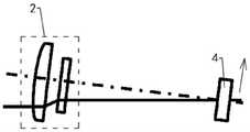
请结合参阅图4A和图4B,图4A是图3所示摄像头模组10处于抖动环境中的初始光路示意图,图4B是图3所示摄像头模组10实现光学防抖时的光路示意图。图4A和图4B中示意出镜头2的一个凸透镜及一个凹透镜结构。图4A和图4B中通过实线示意实际光路,通过点划线示意图像传感器4的理想光路。4A and 4B, FIG. 4A is a schematic diagram of the initial optical path of the
如图4A所示,当摄像头模组10发生抖动时,摄像头模组10的镜头2及图像传感器4均相对入射光线发生倾斜,入射光线经过镜头2后进入图像传感器4的实际光路偏离图像传感器4的理想光路,光线在图像传感器4上的成像区域偏离理想区域。如图4B所示,由于SMA马达3能够驱动图像传感器4在镜头2的光轴20的垂直平面上移动,因此SMA马达3能够驱动图像传感器4从图4A中的原始位置平移至图4B中调整后的位置,使得入射光线经过镜头2后进入图像传感器4的实际光路与调整后的理想光路产生重叠,从而将成像区域调整至理想区域,故而摄像头模组10能够形成高质量图像,实现防抖。As shown in FIG. 4A , when the
在本实施例中,由于图像传感器4相较于镜头2的重量大幅度降低,因此摄像头模组10通过图像传感器4平移方式实现防抖,能够降低SMA马达3的驱动负载,使得SMA马达3的功耗较小,故而摄像头模组10的防抖功耗较低。In this embodiment, since the weight of the image sensor 4 is greatly reduced compared to the
此外,由于镜头2对光线的聚集作用,相较于传统的移动镜头进行防抖的方案,本实施例的摄像头模组10通过SMA马达3驱动图像传感器4进行光路补偿所需要的补偿平移距离更短,因此进一步降低了SMA马达3的功耗,使得摄像头模组10的防抖功耗更低。换言之,在同等功耗下,本实施例的摄像头模组10相较于传统方案具备更好的防抖性能。In addition, due to the light-gathering effect of the
可以理解的是,在本实施例中,在达到相同防抖性能的情况下,图像传感器4的补偿平移距离相较于传统的镜头的补偿平移距离的下降幅度与镜头2的镜片22结构相关。可以通过优化镜头2结构,获得期待的图像传感器4的补偿平移距离范围,以使摄像头模组10的性能更为理想,例如功耗更低、防抖反馈速度更快等。It can be understood that, in the present embodiment, under the condition of achieving the same anti-shake performance, the reduction of the compensation translation distance of the image sensor 4 compared to the compensation translation distance of the conventional lens is related to the structure of the
在本实施例中,由于SMA马达3驱动图像传感器4在镜头2的光轴20的垂直平面上移动,图像传感器4在镜头2的光轴20方向上与模组支架1不发生相对移动,镜头2相对模组支架1固定,因此在镜头2的光轴20方向上,图像传感器4与镜头2之间的距离不变,镜头2为定焦镜头2,摄像头模组10为防抖动的定焦模组。In this embodiment, since the
示例性的,本实施例摄像头模组10可以应用于定焦环境中,例如,可以作为电子设备1000的前置摄像组件300的摄像头模组10使用,本申请对此不作严格限定。Exemplarily, the
请继续参阅图3,SMA马达3包括马达上部件31、马达下部件32、多个支座(hold)33及四根SMA线34。马达上部件31与马达下部件32于摄像头模组10的厚度方向Z上彼此间隔地堆叠设置。图像传感器4固定于马达上部件31。马达下部件32位于马达上部件31远离图像传感器4的一侧。多个支座33位于马达下部件32与马达上部件31之间。多个支座33靠近马达下部件32的一端固定连接马达下部件32,多个支座33靠近马达上部件31的一端滑动连接马达上部件31。四根SMA线34均一端固接马达上部件31,另一端固接马达下部件32。SMA线34通电加热时产生收缩。Please continue to refer to FIG. 3 , the
其中,SMA线34采用形状记忆合金(Shape Memory Alloy,SMA)材料,例如镍钛合金材料。形状记忆合金是一类具有形状记忆效应金属的总称。一般金属材料在受到外力作用后,首先发生的是弹性形变,此时若撤除外力作用,则金属将恢复原来形状,若继续增加外力,当达到金属的自身屈服点之后,会产生塑性形变,外力消除后就留下永久变形,即使加热也不会发生形状恢复。而形状记忆合金是一种在加热升温后能完全消除其在较低的温度下发生的变形,恢复其变形前原始形状的合金材料。形状记忆合金材料工作的基本原理,是将材料加热到某个临界温度以上进行形状记忆热处理(training),并使其发生一定的形变。冷却生成马氏体相后,再次将其加热到临界温度之上时,由低温马氏体相逆相变为高温奥氏体相(即产生逆向转变),从而恢复到变形前所记忆的状态。The
本实施例中,SMA线34通电时,通电产生的热量使得SMA线34的温度上高,实现由低温马氏体相逆相变为高温奥氏体相,恢复到变性前记忆,从而使SMA线34产生收缩。由于SMA线34的收缩导致的长度变化,实质上是由于材料晶相结构转换时产生的,即马氏体与奥氏体之间的转换。而这种因晶体结构变化(即原子与原子之间的间隙变换)的微观粒子之间的引力,使得宏观SMA线34收缩时的拉力较一般磁铁线圈间的电磁力大很多,因此SMA线34的收缩可以驱动更重的负载,即可以实现大载重,故而SMA马达3能够以较小的尺寸实现较大的驱动力。In this embodiment, when the
在本实施例中,由于SMA线34通电加热时产生收缩,会对马达上部件31产生对应的拉力,因此摄像头模组10可以通过控制四根SMA线34的电信号,使四根SMA对马达上部件31施加的合力朝向预期方向,从而驱动马达上部件31携带图像传感器4向预期的方向和位置移动,使得摄像头模组10能够通过平移图像传感器4实现防抖。In this embodiment, since the
此外,相较于传统的防抖马达(也即音圈马达),SMA马达3采用线材驱动方式、而非磁场驱动方式,SMA马达3的结构更为精简,有助于摄像头模组10的小型化,并且可以降低摄像头模组10对周边环境产生的磁干扰。In addition, compared with the traditional anti-shake motor (ie, the voice coil motor), the
可以理解的是,马达上部件31作为承载图像传感器4的载体,只需要实现承载作用及简单的电连接关系,因此马达上部件31的结构相较于传统的防抖马达的载体更为简单,马达上部件31更易实现小型化、轻质化,使得SMA马达3的负载小,摄像头模组10的防抖功耗低。It can be understood that, as the carrier for carrying the image sensor 4, the motor
示例性的,支座33与马达下部件32之间的固定方式有多种,根据支座33的不同材质而定。其中,支座33可以采用粘胶固定方式,也可以采用其他固定方式。例如,支座33采用金属材质时,可以采用粘接方式固定至马达下部件32。例如,支座33采用有机高分子材料,如聚甲醛(polyformaldehyde,POM)时,可以采用热成型粘接方式固定至马达下部件32。在其他一些实施例中,支座33也可以采用其他材质,也可以采用其他固定方式固定至下马达,本申请实施例对此不作严格限定。Exemplarily, there are various ways of fixing between the
如图3所示,摄像头模组10的电路板5位于马达下部件32远离马达上部件31的一侧。电路板5固接模组支架1。示例性的,电路板5部分固定于模组支架1的内侧,部分(图中未示出)伸出至模组支架1的外侧。在其他实施例中,电路板5也可以固定于模组支架1的外侧。此时,模组支架1的一端与SMA马达3固定于电路板5的同一侧板面,SMA马达3位于模组支架1的内侧。As shown in FIG. 3 , the
其中,电路板5位于模组支架1外侧的部分可以电连接电子设备1000的主板500,以使摄像头模组10耦合处理器600。电路板5用于传输摄像头模组10的控制信号及图像信号。示例性的,电路板5用于连接主板500的端部处设有电连接器,该电连接器连接主板500上的电连接器,使得摄像头模组10与电路板5上的电路及器件(如处理器600)电连接。其中,电路板5可以是软硬结合电路板,也可以是柔性电路板,也可以是硬质电路板与柔性电路板相接成的一体化的电路板,本申请不对电路板5的具体架构进行限定。其中,电路板5上的电连接器可以是板对板(board to board,BTB)连接器或者其他。在其他一些实施例中,摄像头模组10与主板500上的电路及器件也可以通过无线连接的方式实现耦合。The part of the
如图3所示,示例性的,马达下部件32可以直接粘接于电路板5,电路板5可以用于承载和固定SMA马达3,以使摄像头模组10的结构稳定性较高。在其他一些实施例中,马达下部件32也可以通过卡合、焊接等其他方式固定于电路板5,本申请实施例不对马达下部件32与电路板5的连接方式进行严格限定。As shown in FIG. 3 , exemplarily, the
如图3所示,示例性的,图像传感器4可以通过多根键合线(bonding wire)41电连接电路板5。键合线41可以为金线或者其他。各键合线41的长度较长。在图像传感器4随马达上部件31相对马达下部件32平移时,图像传感器4相对电路板5平移,键合线41随图像传感器4的平移动作发生适应性变形,键合线41较长时,更易实现形变,且线材不易发生断裂,使得键合线41的可靠性较高,摄像头模组10的使用寿命较长。As shown in FIG. 3 , for example, the image sensor 4 may be electrically connected to the
在其他一些实施例中,马达上部件31形成电路,马达下部件32形成电路。图像传感器4也可以电连接马达上部件31,然后通过马达上部件31及马达下部件32,导通至电路板5。其中,马达上部件31的电路及马达下部件32的电路可以通过电镀方式形成,也可以通过粘接柔性电路板的方式形成,也可以通过嵌埋注塑成型(Insert Molding)埋设金属的方式形成,本申请对此不作严格限定。In other embodiments, the
如图3所示,一些实施例中,摄像头模组10还可以包括红外截止滤光片(IR cutfilter)9。红外截止滤光片9安装于模组支架1内侧且位于镜头2与图像传感器4之间。在摄像头模组10的厚度方向Z上,红外截止滤光片9与镜头2及图像传感器4彼此间隔地堆叠设置。红外截止滤光片9用于过滤红外光,以提高摄像头模组10的成像质量。示例性的,红外截止滤光片9可以采用蓝玻璃(blue glass)。示例性的,红外截止滤光片9可以抵持第二支撑面12设置。在其他一些实施例中,摄像头模组10也可以不设置红外截止滤光片9。As shown in FIG. 3 , in some embodiments, the
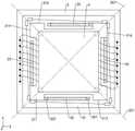
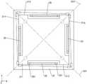
请参阅图5,图5是图3所示摄像头模组10的部分结构的俯视图。其中,图5中示意出摄像头模组10的图像传感器4、SMA马达3以及电路板5。Please refer to FIG. 5 , which is a top view of a partial structure of the
SMA马达3具有第一基准面301和第二基准面302,第一基准面301及第二基准面302均经过镜头2的光轴20。此时,第一基准面301与第二基准面302相交。示例性的,第一基准面301与第二基准面302相互垂直,第一基准面301相对摄像头模组10的XZ平面绕镜头2的光轴20顺时针旋转45°,第二基准面302相对摄像头模组10的YZ平面绕镜头2的光轴20顺时针旋转45°。在其他实施例中,第一基准面301与第二基准面302之间的角度也可以是其他角度。The
图像传感器4、马达上部件31、马达下部件32及电路板5于摄像头模组10的厚度方向Z上堆叠设置。图像传感器4通过两组对称设置的键合线41电连接至电路板5,键合线41跨过马达上部件31及马达下部件32。在其他一些实施例中,键合线41的组数也可以是其他数量,例如四组。键合线41对称设置,有利于在图像传感器4的平移过程中,平衡图像传感器4的受力情况,使得摄像头模组10的防抖性能更佳。多组键合线41可以彼此备份。在其他一些实施例中,键合线41的组数也可以是一组或三组等。The image sensor 4 , the
各SMA线34的一端固定于马达上部件31、另一端固定于马达下部件32。四根SMA线34两两成对,两对SMA线34相对第一基准面301对称设置,同一对的两根SMA线34相对第二基准面302对称设置。示例性的,四根SMA线34包括第一SMA线341、第二SMA线342、第三SMA线343以及第四SMA线344。第一SMA线341和第二SMA线342组成第一对SMA线,第三SMA线343和第四SMA线344组成第二对SMA线。第一对SMA线与第二对SMA线相对第一基准面301对称设置。第一SMA线341与第二SMA线342相对第二基准面302对称设置,第三SMA线343与第四SMA线344相对第二基准面302对称设置。One end of each
在本实施例中,通过限定四根SMA线34的位置关系,使得摄像头模组10可以通过控制四根SMA线34内的电信号,使得四根SMA线34对马达上部件31的合力沿第一基准面301移动或者沿第二基准面302移动,并且可以通过在第一基准面301上的位移和在第二基准面302上的位移的合成位移,使得马达上部件31携带图像传感器4移动至摄像头模组10的XY平面(也即镜头2的光轴20的垂直平面)的任意位置,从而实现图像传感器4平移式防抖。In this embodiment, by defining the positional relationship of the four
如图5所示,示例性的,SMA线34的一端可以通过固定卡爪321固定于马达下部件32,SMA线34的另一端可以通过活动卡爪311固定于马达上部件31。固定卡爪321及活动卡爪311可采用导电材料,或者形成导电结构,以使SMA线34电连接马达上部件31及马达下部件32。As shown in FIG. 5 , exemplarily, one end of the
可以理解的是,摄像头模组10的四根SMA线34在满足上述位置关系要求的情况下,可以有多种具体的连接方式,本实施例以其中一种为例进行描述。It can be understood that, under the condition that the four
示例性的,马达上部件31大致呈矩形板状。马达上部件31包括面向图像传感器4的上板面312及连接于上板面312周缘的周侧面。图像传感器4固定于马达上部件31的上板面312。周侧面包括依次连接的第一侧面313、第二侧面314、第三侧面315及第四侧面316。第一侧面313与第二侧面314相对第二基准面302对称设置。第三侧面315与第二侧面314相对第一基准面301对称设置。第四侧面316与第三侧面315相对第二基准面302对称设置。第一侧面313与第四侧面316相对第一基准面301对称设置。Exemplarily, the motor
在其他一些实施例中,马达上部件31也可以有其他形状,例如圆角矩形板状、圆形板状等形状。可以理解的是,当马达上部件31的周侧面的各个侧面随马达上部件31的形状变化而发生适应性变化。In some other embodiments, the motor
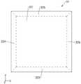
请一并参阅图5和图6,图6是图5所示马达下部件32的俯视图。Please refer to FIG. 5 and FIG. 6 together. FIG. 6 is a top view of the
示例性的,马达下部件32包括正对马达上部件31的中间区域322以及围绕中间区域322设置的边缘区域。多个支座33固定于中间区域322。此时,多个支座33对马达上部件31的支撑更为平稳。示例性的,支座33的数量为四个,四个支座33分别支撑于马达上部件31的四个对角,四个支座33可以两两分别位于第一基准面301和第二基准面302。其中,多个支座33与马达上部件31的边缘之间形成一定距离,使得马达上部件31在移动时,多个支座33能够保持接触马达上部件31而实现对马达上部件31的支撑。Exemplarily, the
马达下部件32的边缘区域包括第一边缘区323、第二边缘区324、第三边缘区325以及第四边缘区326。第一边缘区323与第一侧面313对应设置,第二边缘区324与第二侧面314对应设置,第三边缘区325与第三侧面315对应设置,第四边缘区326与第四侧面316对应设置。其中,第一边缘区323与第四边缘区326相对第一基准面301对称设置。第三边缘区325与第二边缘区324相对第一基准面301对称设置。第四边缘区326与第三边缘区325相对第二基准面302对称设置。第一边缘区323与第四边缘区326相对第一基准面301对称设置。The edge region of the motor
可以理解的是,在本实施例中,马达下部件32大致呈矩形板状。在其他一些实施例中,马达下部件32的形状也可以随马达上部件31的形状变化发生适应性变化。在其他一些实施例中,马达下部件32的形状也可以与马达上部件31的形状不同,本申请对此不作严格限定。It can be understood that, in this embodiment, the motor
可以理解的是,在本实施例中,第一边缘区323、第二边缘区324、第三边缘区325以及第四边缘区326依次连接成连续的边缘区域。在其他实施例中,第一边缘区323、第二边缘区324、第三边缘区325以及第四边缘区326也可以彼此间隔设置,或者部分间隔、部分连续设置,本申请对此不作严格限定。It can be understood that, in this embodiment, the
如图5所示,第一SMA线341的一端固定于马达上部件31的第一侧面313靠近第二侧面314的一端,第一SMA线341的另一端固定于马达下部件32的第一边缘区323靠近第四边缘区326的一端。第二SMA线342与第一SMA线341相对第二基准面302对称设置。第二SMA线342的一端固定于马达上部件31的第二侧面314靠近第一侧面313的一端,第二SMA线342的另一端固定于马达下部件32的第二边缘区324靠近第三边缘区325的一端。第三SMA线343与第二SMA线342相对第一基准面301对称设置。第三SMA线343的一端固定于马达上部件31的第三侧面315靠近第四侧面316的一端,第三SMA线343的另一端固定于马达下部件32的第三边缘区325靠近第二边缘区324的一端。第四SMA线344与第三SMA线343相对第二基准面302对称设置。第四SMA线344的一端固定于马达上部件31的第四侧面316靠近第三侧面315的一端,第四SMA线344的另一端固定于马达下部件32的第四边缘区326靠近第一边缘区323的一端。As shown in FIG. 5 , one end of the
在本实施例中,SMA线34的一端固定于马达上部件31的对角位置、另一端固定于马达下部件32的对角位置,使得SMA线34能够在SMA马达3内部空间有限的情况下具有较为足够的长度,从而具有足够的伸缩量,SMA马达3能够具有更大的驱动行程区间,使得摄像头模组10的防抖性能更佳。In this embodiment, one end of the
在其他一些实施例中,第一SMA线341的一端也可以固定于马达上部件31的第一侧面313靠近第四侧面316的一端,第一SMA线341的另一端固定于马达下部件32的第一边缘区323靠近第二边缘区324的一端,第二SMA线342、第三SMA线343以及第四SMA线344随第一SMA线341的位置变化发生适应性变化。In some other embodiments, one end of the
可以理解的是,在一些实施例中,四根SMA线34的延伸方向分别与马达上部件31的四个侧面平行,以方便四根SMA线34驱动马达上部件31移动。图5中为方便示意出多根SMA线34的结构及位置差异,将SMA线34绘制成倾斜。此外,在摄像头模组10的厚度方向Z上,四根SMA线34的高度一致,也即SMA线连接马达上部件31的固定端和连接马达下部件32的活动端的高度一致,以方便四根SMA线34驱动马达上部件31移动。图3中为方便示意出多根SMA线34的结构及位置差异,将SMA线34绘制成倾斜。示例性的,可以通过设计用于固定SMA线34的卡爪(例如图5中固定卡爪321和活动卡爪311)结构,使得SMA线34的位置满足需求。例如,可以使图5中活动卡爪311的体积较大,或者设计成小凸台结构,使得第一SMA线341平行于马达上部件31的第一侧面313。当然,在其他实施例中,卡爪也可以有其他实现结构,本申请对此不作严格限定。It can be understood that, in some embodiments, the extending directions of the four
请参阅图7,图7是图5所示SMA马达3驱动图像传感器4平移的结构示意图。以下结合图7示例性地说明SMA马达3驱动图像传感器4平移的过程。Please refer to FIG. 7 . FIG. 7 is a schematic structural diagram of the
示意第一基准面301的远离第二基准面302的两个方向分别为A+方向和A-方向,第二基准面302的远离第一基准面301的两个方向分别为B+方向和B-方向。It is indicated that the two directions of the
四根SMA线34均通电,第一SMA线341产生拉力F1,第二SMA线342产生拉力F2,第三SMA线343产生拉力F3,第四SMA线344产生拉力F4。当F1+F4>F2+F3时,马达上部件31携带图像传感器4沿A+方向移动;当F1+F4<F2+F3时,马达上部件31携带图像传感器4沿A-方向移动;当F1+F2>F3+F4时,马达上部件31携带图像传感器4沿B-方向移动;当F1+F2<F3+F4时,马达上部件31携带图像传感器4沿B+方向移动。当四根SMA线34的作用力平衡时,马达上部件31及图像传感器4处于稳定状态。The four
请参阅图8,图8是图3所示摄像头模组10的部分结构示意图。Please refer to FIG. 8 , which is a partial structural diagram of the
马达上部件31设有第一导电件317,支座33设有第二导电件331,马达下部件32设有第三导电件327及第四导电件328。第三导电件327电连接电路板5与SMA线34的一端,SMA线34的另一端电连接第一导电件317,第一导电件317经第二导电件331电连接第四导电件328,第四导电件328电连接电路板5。The
在本实施例中,电路板5、第三导电件327、SMA线34、第一导电件317、第二导电件331以及第四导电件328形成回路,电路板5能够对SMA线34供电,以通过电信号控制SMA线34的收缩情况。In this embodiment, the
需要说明的是,摄像头模组10通过对不同的SMA线34输入不同的电信号,使不同的SMA线34能够彼此独立地实现收缩。一些实施例中,不同SMA线34对应的通路彼此独立。例如,第一导电件317、第二导电件331、第三导电件327及第四导电件328的数量均为四个,一个第三导电件327、一根SMA线34、一个第一导电件317、一个第二导电件331及一个第四导电件328形成一个通路,SMA马达3形成四个彼此独立的通路。另一些实施例中,不同SMA线34对应的通路部分共用,以简化电路结构。例如:第三导电件327的数量为四个,第一导电件317、第二导电件331及第四导电件328的数量均为一个,四个第三导电件327分别与四根SMA线34的一端连接,四根SMA线34的另一端均连接至第一导电件317,第二导电件331连接第一导电件317及第四导电件328。在本实施例中,不同的SMA线34的通路具有不同的正极输入,共同相同的负极输出,不同的SMA线34的通路仍可以输入不同的电信号。It should be noted that the
其中,第一导电件317、第二导电件331、第三导电件327及第四导电件328均可以有多种实现结构,包括但不限于导线、导电贴片、导电结构件等。示例性的,第一导电件317可以为马达上部件31的电路的一部分,第三导电件327及第四导电件328可以为马达下部件32的电路的一部分。第二导电件331可以通过电镀方式形成,也可以通过粘接柔性电路板的方式形成,也可以通过嵌埋注塑成型(Insert Molding)埋设金属的方式形成,本申请对此不作严格限定。The first
请一并参阅图9和图10,图9是图3所示摄像头模组10的部分结构在另一些实施例中的俯视图,图10是图9所示SMA马达3的结构示意图。其中,图9中示意出摄像头模组10的图像传感器4、SMA马达3以及电路板5。以下主要描述本实施例与前述实施例的不同,本实施例与前述实施例相同的大部分内容不再赘述。Please refer to FIG. 9 and FIG. 10 together. FIG. 9 is a top view of a partial structure of the
一些实施例中,SMA马达3还可以包括两个弹簧臂35(spring arm)。图9和图10中为较为突出显示弹簧臂35,对弹簧臂35的结构进行剖面线填充示意。弹簧臂35呈L形。弹簧臂35均包括固定端部351和活动端部352。弹簧臂35的活动端部352固定于马达上部件31,弹簧臂35的固定端部351固定于马达下部件32,例如可以固定于马达下部件32的中间区域322。两个弹簧臂35中心对称设置,且对称中心为第一基准面301与第二基准面302的相交线。中心对称的两个弹簧臂35在马达上部件31发生移动时,产生相同的形变。In some embodiments, the
在本实施例中,SMA马达3通过设置弹簧臂35,不仅能够在SMA线34通电驱动马达上部件31携带图像传感器4移动的过程中,平衡和缓冲马达上部件31的受力,使得马达上部件31的移动更为平稳,而且能够在SMA线34断电时,通过其在SMA线34通电驱动马达上部件31移动的过程中产生形变所形成的弹性力、驱动马达上部件31携带图像传感器4移回初始位置。In this embodiment, by setting the
此外,由于弹簧臂35的固定端部351固定于马达下部件32的中间区域322,因此弹簧臂35的活动空间与SMA线34的活动空间错开,从而可以避免弹簧臂35和SMA线34在马达上部件31的移动过程中发生干涉。In addition, since the
在其他一些实施例中,弹簧臂35的固定端部351也可以固定于马达下部件32的周缘区域,本申请对弹簧臂35的固定端部351的固定位置不作严格限定。In some other embodiments, the
示例性的,两个弹簧臂35可以一体成型于马达上部件31,以简化SMA马达3的组装结构,使得SMA马达3的结构稳定性更佳。在其他实施例中,弹簧臂35的活动端部352也可以通过焊接等方式固定于马达上部件31,本申请对此不作严格限定。弹簧臂35的固定端部351可以通过焊接等方式固定于马达下部件32,本申请对此不作严格限定。Exemplarily, the two
如图10所示,示例性的,弹簧臂35包括第一枝节35a和连接第一枝节35a的第二枝节35b。第一枝节35a远离第二枝节35b的一端为活动端部352,固接马达上部件31;第二枝节35b远离第一枝节35a的一端为固定端部351,固接马达下部件32。两个弹簧臂35中的其中一个弹簧臂35的第一枝节35a平行于第一侧面313,第二枝节35b平行于第四侧面316。两个弹簧臂35的另一个弹簧臂35的第一枝节35a平行于第三侧面315,第二枝节35b平行于第二侧面314。在本实施例中,两个弹簧臂35的形状及位置与马达上部件31相适配,故而两个弹簧臂35对马达上部件31的平衡和缓冲效果更佳。As shown in FIG. 10, the
如图10所示,一些实施例中,马达上部件31的周侧面部分凹陷形成两个L形的避让槽310。各避让槽310均自马达上部件31的一个侧面延伸至另一个侧面。两个弹簧臂35分别对应两个避让槽310设置。弹簧臂35的活动端部352固定于避让槽310的槽侧壁,避让槽310的槽侧壁连接马达上部件31的周侧面。As shown in FIG. 10 , in some embodiments, two L-shaped
在本实施例中,SMA马达3通过马达上部件31的避让槽310及避让槽310下方的空间作为弹簧臂35的安装空间及活动空间,使得弹簧臂35与马达上部件31的排布更为紧凑,SMA马达3更易实现小型化。In this embodiment, the
在另一些实施例中,弹簧臂35的活动端部352也可以固定于马达上部件31面向马达下部件32的板面。此时,马达上部件31可以不设置避让槽310,马达上部件31的结构较为完整,马达上部件31更易加工。In other embodiments, the
请参阅图11,图11是图9所示SMA马达3在另一些实施例中的结构示意图。以下主要描述本实施例与前述实施例的不同,本实施例与前述实施例相同的大部分内容不再赘述。图11中为较为突出显示弹簧臂35,对弹簧臂35的结构进行剖面线填充示意。Please refer to FIG. 11 . FIG. 11 is a schematic structural diagram of the
在本实施例中,两个弹簧臂35中的其中一个弹簧臂35的第一枝节35a平行于第一侧面313,第二枝节35b平行于第四侧面316。弹簧臂35的第一枝节35a远离第二枝节35b的一端为固定端部351,固接马达下部件32;第二枝节35b远离第一枝节35a的一端为活动端部352,固接马达上部件31。In this embodiment, the
请一并参阅图12和图13,图12是图3所示摄像头模组10的部分结构在再一些实施例中的俯视图,图13是图12所示SMA马达3的结构示意图。其中,图12中示意出摄像头模组10的图像传感器4、SMA马达3以及电路板5。以下主要描述本实施例与前述实施例的不同,本实施例与前述实施例相同的大部分内容不再赘述。Please refer to FIG. 12 and FIG. 13 together. FIG. 12 is a top view of a partial structure of the
一些实施例中,SMA马达3还包括四个弹簧臂35。示例性的,弹簧臂35呈长条形。弹簧臂35均包括固定端部351和活动端部352。弹簧臂35的活动端部352固定于马达上部件31,弹簧臂35的固定端部351固定于马达下部件32,例如固定于马达下部件32的中间区域322。四个弹簧臂35两两成对,两对弹簧臂35相对第一基准面301对称设置,同一对的两个弹簧臂35相对第二基准面302对称设置。In some embodiments, the
在本实施例中,SMA马达3通过设置弹簧臂35,不仅能够在SMA线34通电驱动马达上部件31携带图像传感器4移动的过程中,平衡和缓冲马达上部件31的受力,使得马达上部件31的移动更为平稳,而且能够在SMA线34断电时,通过其在SMA线34通电驱动马达上部件31移动的过程中产生形变所形成的弹性力、驱动马达上部件31携带图像传感器4移回初始位置。此外,四个弹簧臂35的排布关系与SMA线34的排布关系相对应,因此四个弹簧臂35能够更好地实现平衡作用和回复作用。In this embodiment, by setting the
此外,由于弹簧臂35的固定端部351固定于马达下部件32的中间区域322,因此弹簧臂35的活动空间与SMA线34的活动空间错开,从而可以避免弹簧臂35和SMA线34在马达上部件31的移动过程中发生干涉。In addition, since the
示例性的,四个弹簧臂35可以分别平行于马达上部件31的四个侧面(313、314、315、316)。Exemplarily, the four
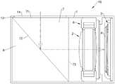
请参阅图14,图14是本申请实施例提供的摄像头模组10在第二实施例中的结构示意图。以下主要描述本实施例与前述实施例的不同,本实施例与前述实施例相同的大部分内容不再赘述。Please refer to FIG. 14 . FIG. 14 is a schematic structural diagram of the
在一些实施例中,摄像头模组10还可以包括音圈马达6。音圈马达6固定于模组支架1内侧,镜头2安装于音圈马达6,音圈马达6用于驱动镜头2在镜头2的光轴20的平行方向上移动。In some embodiments, the
在本实施例中,摄像头模组10既可以通过SMA马达3驱动图像传感器4在镜头2的光轴20的垂直平面上平移,使得图像传感器4与镜头2的相对位置发生变化,以实现防抖;摄像头模组10还可以通过音圈马达6驱动镜头2移动,使得镜头2与图像传感器4在镜头2的光轴20的平行方向上的距离发生变化,以实现自动对焦(auto focus,AF)。换言之,摄像头模组10具备自动对焦及光学防抖功能。In this embodiment, the
示例性的,本实施例的摄像头模组10能够适用于需求高质量图像的场景中,例如,摄像头模组10可以用作电子设备1000的后置摄像组件400的摄像头模组10,本申请对此不作严格限定。Exemplarily, the
示例性的,如图14所示,镜头2包括镜筒21及固定于镜头2内侧的至少一个镜片22。音圈马达6包括马达支架61、磁铁组件62、音圈63、上弹簧64及下弹簧65。马达支架61位于模组支架1内侧且固接模组支架1。磁铁组件62固定于马达支架61内侧。镜头2位于磁铁组件62内侧。音圈63位于镜筒21与磁铁组件62之间且固接镜筒21。音圈63通电时,带动镜头2沿镜头2的光轴20的平行方向移动。上弹簧64的一侧固接镜筒21的上端、另一侧固接马达支架61。下弹簧65的一侧固接镜筒21的下端、另一侧固接马达支架61。Exemplarily, as shown in FIG. 14 , the
请参阅图15,图15是本申请实施例提供的摄像头模组10在第三实施例中的结构示意图。以下主要描述本实施例与前述实施例的不同,本实施例与前述实施例相同的大部分内容不再赘述。Please refer to FIG. 15 . FIG. 15 is a schematic structural diagram of the
在一些实施例中,摄像头模组10也可以为潜望式的长焦摄像头模组。摄像头模组10还包括棱镜(prism)7。棱镜7固定于模组支架1的内侧、且位于镜头2的入光侧。模组支架1具有入光孔13,入光孔13正对棱镜7设置。环境光线经过棱镜7后发生偏转,从而顺利进入镜头2。摄像头模组10通过棱镜7偏转光路,因此摄像头模组10能够将模组厚度分布在两个方向上,避免因模组厚度过大导致装配难等问题。摄像头模组10包括用于实现镜头2自动对焦的音圈马达6。In some embodiments, the
传统的潜望式的摄像头模组设有多组棱镜驱动马达,通过棱镜驱动马达驱动棱镜转动以实现防抖,结构复杂、难实现且可靠性差。本实施例摄像头模组10通过SMA马达3驱动图像传感器4在镜头2的光轴20的垂直平面上移动、以实现光学防抖,故而相较于传统方案,本实施例摄像头模组10省略能够棱镜驱动马达,将棱镜7定于模组支架1,从而在满足长焦防抖性能的前提下,简化模组结构、增加结构可靠性。The traditional periscope camera module is provided with multiple groups of prism drive motors, and the prism is driven to rotate by the prism drive motors to realize anti-shake, which is complicated in structure, difficult to realize and has poor reliability. The
示例性的,摄像头模组10还包括棱镜支架8,棱镜支架8固定于模组支架1,棱镜7固定于棱镜支架8。棱镜7呈三棱柱形。环境光经棱镜7的面向入光孔13的直边侧面71进入棱镜7、在棱镜7的斜边侧面72发生反射、自棱镜7的面向镜头2的另一直边侧面73射出,然后经镜头2摄像图像传感器4。Exemplarily, the
示例性的,摄像头模组10还可以包括光栏14。光栏14安装于模组支架1且覆盖入光孔13。光栏14可用于导光、防尘、外观修饰等。Exemplarily, the
请参阅图16,图16是本申请实施例提供的摄像头模组10在第四实施例中的结构示意图。以下主要描述本实施例与前述实施例的不同,本实施例与前述实施例相同的大部分内容不再赘述。Please refer to FIG. 16 . FIG. 16 is a schematic structural diagram of the
在本实施例中,棱镜7直接固定于模组支架1。棱镜7的斜边侧面72同时面向入光孔13和镜头2,环境光在棱镜7的斜边侧面72发射后直接进入镜头2,环境光不再进入棱镜7内部。此时,环境光在传输过程中的损耗较小,有利于提高摄像头模组10的成像质量。In this embodiment, the
示例性的,图15和图16所示摄像头模组10可以适用于有长焦拍摄和防抖需求且安装空间较小的环境中,例如,摄像头模组10可以用作电子设备1000的后置摄像组件400的摄像头模组10,本申请对此不作严格限定。Exemplarily, the
以上,仅为本申请的具体实施例,但本申请的保护范围并不局限于此,任何熟悉本技术领域的技术人员在本申请揭露的技术范围内,可轻易想到变化或替换,都应涵盖在本申请的保护范围之内;在不冲突的情况下,本申请的实施例及实施例中的特征可以相互组合。因此,本申请的保护范围应以权利要求的保护范围为准。The above are only specific embodiments of the present application, but the protection scope of the present application is not limited thereto. Any person skilled in the art can easily think of changes or replacements within the technical scope disclosed in the present application, and should cover Within the protection scope of the present application; the embodiments of the present application and the features in the embodiments may be combined with each other under the condition of no conflict. Therefore, the protection scope of the present application shall be subject to the protection scope of the claims.
Claims (12)
Priority Applications (4)
| Application Number | Priority Date | Filing Date | Title |
|---|---|---|---|
| CN201911209202.6ACN112887521B (en) | 2019-11-30 | 2019-11-30 | Camera modules and electronic equipment |
| EP20891619.7AEP4057610A4 (en) | 2019-11-30 | 2020-11-11 | CAMERA MODULE AND ELECTRONIC DEVICE |
| PCT/CN2020/128035WO2021104017A1 (en) | 2019-11-30 | 2020-11-11 | Camera module and electronic device |
| US17/780,899US12177549B2 (en) | 2019-11-30 | 2020-11-11 | Camera system and shape memory alloy motor |
Applications Claiming Priority (1)
| Application Number | Priority Date | Filing Date | Title |
|---|---|---|---|
| CN201911209202.6ACN112887521B (en) | 2019-11-30 | 2019-11-30 | Camera modules and electronic equipment |
Publications (2)
| Publication Number | Publication Date |
|---|---|
| CN112887521A CN112887521A (en) | 2021-06-01 |
| CN112887521Btrue CN112887521B (en) | 2022-07-26 |
Family
ID=76039533
Family Applications (1)
| Application Number | Title | Priority Date | Filing Date |
|---|---|---|---|
| CN201911209202.6AActiveCN112887521B (en) | 2019-11-30 | 2019-11-30 | Camera modules and electronic equipment |
Country Status (4)
| Country | Link |
|---|---|
| US (1) | US12177549B2 (en) |
| EP (1) | EP4057610A4 (en) |
| CN (1) | CN112887521B (en) |
| WO (1) | WO2021104017A1 (en) |
Families Citing this family (21)
| Publication number | Priority date | Publication date | Assignee | Title |
|---|---|---|---|---|
| JP2016523389A (en) | 2013-07-04 | 2016-08-08 | コアフォトニクス リミテッド | Compact telephoto lens assembly |
| CN112433331B (en) | 2015-01-03 | 2022-07-08 | 核心光电有限公司 | Miniature telephoto lens module and camera using the same |
| CN112394467B (en) | 2015-04-16 | 2023-06-09 | 核心光电有限公司 | Autofocus and Optical Image Stabilization in a Compact Folding Camera |
| US10230898B2 (en) | 2015-08-13 | 2019-03-12 | Corephotonics Ltd. | Dual aperture zoom camera with video support and switching / non-switching dynamic control |
| KR20240051317A (en) | 2016-07-07 | 2024-04-19 | 코어포토닉스 리미티드 | Linear ball guided voice coil motor for folded optic |
| US11333955B2 (en) | 2017-11-23 | 2022-05-17 | Corephotonics Ltd. | Compact folded camera structure |
| US11770609B2 (en) | 2020-05-30 | 2023-09-26 | Corephotonics Ltd. | Systems and methods for obtaining a super macro image |
| US11637977B2 (en) | 2020-07-15 | 2023-04-25 | Corephotonics Ltd. | Image sensors and sensing methods to obtain time-of-flight and phase detection information |
| CN214540194U (en)* | 2021-03-12 | 2021-10-29 | 广东海德亚科技有限公司 | Lens module and electronic equipment |
| CN113489872B (en)* | 2021-07-05 | 2023-04-07 | 维沃移动通信有限公司 | Filming device and electronic equipment |
| CN115643488A (en)* | 2021-07-20 | 2023-01-24 | 格科微电子(上海)有限公司 | Optical anti-shake device and camera module |
| WO2023002371A1 (en)* | 2021-07-21 | 2023-01-26 | Corephotonics Ltd. | Pop-out mobile cameras and actuators |
| CN113640999A (en)* | 2021-07-27 | 2021-11-12 | 常州市瑞泰光电有限公司 | Optical drive assembly |
| CN113489888B (en)* | 2021-08-03 | 2023-05-19 | Oppo广东移动通信有限公司 | Camera module and electronic equipment |
| CN113784027B (en)* | 2021-09-09 | 2023-06-23 | 东莞华贝电子科技有限公司 | Periscope type camera assembly and electronic equipment |
| CN113747034B (en)* | 2021-09-30 | 2023-06-23 | 维沃移动通信有限公司 | Camera module and electronic equipment |
| US12328505B2 (en) | 2022-03-24 | 2025-06-10 | Corephotonics Ltd. | Slim compact lens optical image stabilization |
| CN114845022B (en)* | 2022-04-26 | 2024-10-15 | 东莞市立阳精密科技有限公司 | SMA camera module platform |
| CN117560553A (en)* | 2022-08-02 | 2024-02-13 | 华为技术有限公司 | SMA motor, camera module and electronic equipment |
| GB2621604A (en)* | 2022-08-17 | 2024-02-21 | Cambridge Mechatronics Ltd | Actuator assembly and method of assembling an actuator assembly |
| US20240312147A1 (en)* | 2023-03-16 | 2024-09-19 | SoftEye, Inc. | Apparatus and methods for augmenting vision with region-of-interest based processing |
Family Cites Families (30)
| Publication number | Priority date | Publication date | Assignee | Title |
|---|---|---|---|---|
| WO2007113478A1 (en)* | 2006-03-30 | 2007-10-11 | 1...Limited | Camera lens actuation apparatus |
| US8077411B2 (en) | 2008-01-24 | 2011-12-13 | E-Pin Optical Industry Co., Ltd. | Lens displacement mechanism using shaped memory alloy |
| US8848064B2 (en)* | 2008-09-12 | 2014-09-30 | Cambridge Mechatronics Limited | Optical image stabilization comprising shape memory alloy actuators |
| JP2011209467A (en) | 2010-03-29 | 2011-10-20 | Seiko Instruments Inc | Drive module and electronic device |
| US9137429B2 (en)* | 2010-08-09 | 2015-09-15 | Cambridge Mechatronics Limited | Camera apparatus |
| JP2012047907A (en)* | 2010-08-25 | 2012-03-08 | Seiko Instruments Inc | Drive module, electronic apparatus, and control method of drive module |
| GB201019532D0 (en)* | 2010-11-18 | 2010-12-29 | Cambridge Mechatronics Ltd | Optical image stablisation drive |
| TWI416240B (en)* | 2011-03-30 | 2013-11-21 | Largan Precision Co Ltd | Photographing module |
| US8891185B2 (en)* | 2011-08-16 | 2014-11-18 | Flextronics Ap, Llc | Camera module and method for manufacturing same |
| GB2514071B (en)* | 2012-02-16 | 2015-09-16 | Cambridge Mechatronics Ltd | Shape memory alloy actuation apparatus |
| JP6289451B2 (en)* | 2012-05-25 | 2018-03-07 | ケンブリッジ メカトロニクス リミテッド | Shape memory alloy actuator |
| CN103529536B (en)* | 2012-07-06 | 2018-05-08 | 河南省酷美智能科技有限公司 | Actuator and camera module with same |
| TWI468769B (en)* | 2013-12-11 | 2015-01-11 | Tdk Taiwan Corp | An apparatus having a spring plate connecting with 3d circuit terminals |
| GB201403803D0 (en)* | 2014-03-04 | 2014-04-16 | Cambridge Mechatronics Ltd | SMA actuator |
| GB201517202D0 (en) | 2015-09-29 | 2015-11-11 | Cambridge Mechatronics Ltd | OIS actuator improvements |
| KR102459243B1 (en)* | 2015-10-08 | 2022-10-26 | 삼성전자 주식회사 | Electronic device and method for photographing thereof |
| US11187916B2 (en)* | 2015-10-28 | 2021-11-30 | Cambridge Mechatronics Limited | Camera assembly providing optical image stabilization |
| WO2017181387A1 (en) | 2016-04-21 | 2017-10-26 | 深圳市大疆创新科技有限公司 | Unmanned aircraft and camera assembly |
| US11199182B2 (en)* | 2016-12-16 | 2021-12-14 | Hutchinson Technology Incorporated | Sensor shift structures in optical image stabilization suspensions |
| CN107493421B (en)* | 2017-09-30 | 2020-09-11 | 北京小米移动软件有限公司 | Camera module, electronic equipment, camera module control method and device |
| CN107682604A (en)* | 2017-10-18 | 2018-02-09 | 维沃移动通信有限公司 | Camera and mobile terminal |
| GB201717855D0 (en) | 2017-10-30 | 2017-12-13 | Cambridge Mechatronics Ltd | SMA actuator bearings |
| CN208207475U (en)* | 2018-03-09 | 2018-12-07 | 欧菲影像技术(广州)有限公司 | The camera module and its camera of mobile terminal |
| US10884237B2 (en) | 2018-05-23 | 2021-01-05 | Lg Electronics Inc. | Camera with an image sensor generating an image signal based on input light reflected by a prism apparatus and passing through lens apparatus, and terminal including the same |
| CN109061827B (en) | 2018-09-13 | 2025-03-28 | 昆山联滔电子有限公司 | Lens driving device and camera module |
| GB201819864D0 (en)* | 2018-12-05 | 2019-01-23 | Cambridge Mechatronics Ltd | Methods and apparatus for controlling power delivered to an SMA actuator |
| WO2020152481A1 (en)* | 2019-01-25 | 2020-07-30 | Cambridge Mechatronics Limited | Improvements in and relating to pwm synchronisation |
| US11258951B2 (en)* | 2019-06-27 | 2022-02-22 | Motorola Mobility Llc | Miniature camera device for stabilized video using shape memory alloy actuators |
| EP4030217B1 (en)* | 2019-09-18 | 2025-05-07 | Ningbo Sunny Opotech Co., Ltd. | Periscope camera module and electronic device |
| US12313902B2 (en)* | 2021-02-19 | 2025-05-27 | Tdk Taiwan Corp. | Optical element driving mechanism |
- 2019
- 2019-11-30CNCN201911209202.6Apatent/CN112887521B/enactiveActive
- 2020
- 2020-11-11EPEP20891619.7Apatent/EP4057610A4/enactivePending
- 2020-11-11USUS17/780,899patent/US12177549B2/enactiveActive
- 2020-11-11WOPCT/CN2020/128035patent/WO2021104017A1/ennot_activeCeased
Also Published As
| Publication number | Publication date |
|---|---|
| WO2021104017A1 (en) | 2021-06-03 |
| EP4057610A4 (en) | 2023-01-04 |
| US12177549B2 (en) | 2024-12-24 |
| US20230022701A1 (en) | 2023-01-26 |
| EP4057610A1 (en) | 2022-09-14 |
| CN112887521A (en) | 2021-06-01 |
Similar Documents
| Publication | Publication Date | Title |
|---|---|---|
| CN112887521B (en) | Camera modules and electronic equipment | |
| CN112887520B (en) | Camera module and electronic equipment | |
| CN113050340B (en) | Camera module | |
| WO2021108972A1 (en) | Camera module and electronic device | |
| CN209299370U (en) | Camera module and smart terminal | |
| KR20180135299A (en) | Lens driving apparatus and camera module including the same | |
| CN113542579B (en) | Image sensor anti-shake components, camera devices and electronic equipment | |
| US20150116591A1 (en) | Camera module | |
| WO2022105748A1 (en) | Sma motor, camera module and electronic device | |
| CN112887519B (en) | Camera module and electronic equipment | |
| CN119998714A (en) | Motors, camera modules and electronic devices | |
| EP4403981A1 (en) | Optical anti-shake unit, camera module, and electronic device | |
| WO2023001204A1 (en) | Optical lens, photographing module and electronic device | |
| CN114827437B (en) | A kind of cloud platform module, camera module and electronic equipment | |
| CN113467043B (en) | Movable piece, motor, lens module and electronic equipment | |
| WO2022042209A1 (en) | Camera module, photographing module and terminal | |
| TWI797006B (en) | Periscope camera module and electronic device | |
| CN115250319B (en) | SMA motor, camera module and electronic equipment | |
| US20230367135A1 (en) | Camera device and optical instrument | |
| CN116419047A (en) | Camera module and electronic equipment | |
| CN217932225U (en) | Lens module, camera module and electronic equipment | |
| KR102872782B1 (en) | Camera module and optical apparatus | |
| CN115529400A (en) | SMA motor, camera module and electronic equipment | |
| CN116594242A (en) | Image pickup device and portable electronic apparatus | |
| WO2025179815A1 (en) | Camera driving motor, camera module and electronic device |
Legal Events
| Date | Code | Title | Description |
|---|---|---|---|
| PB01 | Publication | ||
| PB01 | Publication | ||
| SE01 | Entry into force of request for substantive examination | ||
| SE01 | Entry into force of request for substantive examination | ||
| GR01 | Patent grant | ||
| GR01 | Patent grant |