CN112873188B - Self-assembled modular robot unit, robot, assembly and control method - Google Patents
Self-assembled modular robot unit, robot, assembly and control methodDownload PDFInfo
- Publication number
- CN112873188B CN112873188BCN202110082466.0ACN202110082466ACN112873188BCN 112873188 BCN112873188 BCN 112873188BCN 202110082466 ACN202110082466 ACN 202110082466ACN 112873188 BCN112873188 BCN 112873188B
- Authority
- CN
- China
- Prior art keywords
- robot
- module
- self
- unit
- docking
- Prior art date
- Legal status (The legal status is an assumption and is not a legal conclusion. Google has not performed a legal analysis and makes no representation as to the accuracy of the status listed.)
- Active
Links
Images


Classifications
- B—PERFORMING OPERATIONS; TRANSPORTING
- B25—HAND TOOLS; PORTABLE POWER-DRIVEN TOOLS; MANIPULATORS
- B25J—MANIPULATORS; CHAMBERS PROVIDED WITH MANIPULATION DEVICES
- B25J9/00—Programme-controlled manipulators
- B25J9/08—Programme-controlled manipulators characterised by modular constructions
- B—PERFORMING OPERATIONS; TRANSPORTING
- B25—HAND TOOLS; PORTABLE POWER-DRIVEN TOOLS; MANIPULATORS
- B25J—MANIPULATORS; CHAMBERS PROVIDED WITH MANIPULATION DEVICES
- B25J17/00—Joints
- B—PERFORMING OPERATIONS; TRANSPORTING
- B25—HAND TOOLS; PORTABLE POWER-DRIVEN TOOLS; MANIPULATORS
- B25J—MANIPULATORS; CHAMBERS PROVIDED WITH MANIPULATION DEVICES
- B25J5/00—Manipulators mounted on wheels or on carriages
- B25J5/005—Manipulators mounted on wheels or on carriages mounted on endless tracks or belts
- B—PERFORMING OPERATIONS; TRANSPORTING
- B25—HAND TOOLS; PORTABLE POWER-DRIVEN TOOLS; MANIPULATORS
- B25J—MANIPULATORS; CHAMBERS PROVIDED WITH MANIPULATION DEVICES
- B25J9/00—Programme-controlled manipulators
- B25J9/06—Programme-controlled manipulators characterised by multi-articulated arms
- B25J9/065—Snake robots
- B—PERFORMING OPERATIONS; TRANSPORTING
- B62—LAND VEHICLES FOR TRAVELLING OTHERWISE THAN ON RAILS
- B62D—MOTOR VEHICLES; TRAILERS
- B62D57/00—Vehicles characterised by having other propulsion or other ground- engaging means than wheels or endless track, alone or in addition to wheels or endless track
- B62D57/02—Vehicles characterised by having other propulsion or other ground- engaging means than wheels or endless track, alone or in addition to wheels or endless track with ground-engaging propulsion means, e.g. walking members
- B62D57/032—Vehicles characterised by having other propulsion or other ground- engaging means than wheels or endless track, alone or in addition to wheels or endless track with ground-engaging propulsion means, e.g. walking members with alternately or sequentially lifted supporting base and legs; with alternately or sequentially lifted feet or skid
- Y—GENERAL TAGGING OF NEW TECHNOLOGICAL DEVELOPMENTS; GENERAL TAGGING OF CROSS-SECTIONAL TECHNOLOGIES SPANNING OVER SEVERAL SECTIONS OF THE IPC; TECHNICAL SUBJECTS COVERED BY FORMER USPC CROSS-REFERENCE ART COLLECTIONS [XRACs] AND DIGESTS
- Y02—TECHNOLOGIES OR APPLICATIONS FOR MITIGATION OR ADAPTATION AGAINST CLIMATE CHANGE
- Y02T—CLIMATE CHANGE MITIGATION TECHNOLOGIES RELATED TO TRANSPORTATION
- Y02T10/00—Road transport of goods or passengers
- Y02T10/60—Other road transportation technologies with climate change mitigation effect
- Y02T10/70—Energy storage systems for electromobility, e.g. batteries
Landscapes
- Engineering & Computer Science (AREA)
- Mechanical Engineering (AREA)
- Robotics (AREA)
- Chemical & Material Sciences (AREA)
- Combustion & Propulsion (AREA)
- Transportation (AREA)
- Manipulator (AREA)
Abstract
Translated fromChinese
Description
Translated fromChinese技术领域technical field
本发明涉及模块化机器人技术领域,尤其涉及一种自组装模块化机器人单元、机器人、组装及控制方法。The invention relates to the technical field of modular robots, in particular to a self-assembled modular robot unit, a robot, an assembly and a control method.
背景技术Background technique
在工业等传统应用领域中,机器人的任务及环境相对固定,多采用构型结构相对固定的移动机器人、关节式机器人,这些机器人在特定工作场景和已知结构信息中可完成特定任务。而在深空探测、灾难救援和家用服务等新兴领域中通常存在多样化、非结构化的任务。例如在星球深空探测、应急救援中,存在表面地形复杂,如高度障碍、楼梯、洞穴等,作业地域广泛,需要完成多种任务,适应不同的工作环境,因此,需要机器人完全自主构建具备强通过能力、多任务适应能力的平台,并在必要时进行结构变换,满足不同需求。以往固定结构机器人受到其单一形态的限制,很难满足多样化和变结构的任务需求。而模块化机器人系统能够利用自组装、自重构等特性在离散或者连接的情况下改变自身构型以适应多种任务,对解决特殊环境下的复杂任务具有重要意义。In traditional application fields such as industry, the tasks and environments of robots are relatively fixed, and mobile robots and articulated robots with relatively fixed configuration structures are mostly used. These robots can complete specific tasks in specific work scenarios and known structural information. In emerging fields such as deep space exploration, disaster relief, and home services, there are usually diverse and unstructured tasks. For example, in planetary deep space exploration and emergency rescue, there are complex surface terrains, such as height obstacles, stairs, caves, etc., and the operation area is extensive, and it is necessary to complete various tasks and adapt to different working environments. Therefore, it is necessary for the robot to be fully autonomous. A platform with capabilities, multitasking adaptability, and, where necessary, structural changes to meet different needs. In the past, fixed-structure robots were limited by their single form, and it was difficult to meet the requirements of diverse and variable-structure tasks. The modular robot system can use the characteristics of self-assembly and self-reconfiguration to change its configuration in discrete or connected situations to adapt to various tasks, which is of great significance for solving complex tasks in special environments.
模块化机器人主要是通过个体与个体之间、个体与环境之间的局部交互,进行结构重组,产生系统行为,从而具有自重构、自组装等特性。目前,包括(1)晶格式自重构机器人,如MetaMorphic、Catoms、Crystalline、Fraca和M-BLOCK等机器人,模块的自主移动主要依赖组合后模块的运动能力,不具备独立自主移动能力或者连接后不具备关节运动能力;(2)关节式自重构机器人,如PolyBot、CKBot、YaMoR、M-TRAN、Superbot、UBot、Sporiwutz和Roombot等机器人,每个模块一般具有旋转自由度,具有多关节机器人的优势,可形成如机械臂、抓手或者腿等结构,但模块不具备独立自主移动能力;(3)自组装机器人,如S-bot、E-puck和Oung的自组装飞行阵列等,一群模块可通过移动、相互连接,自动从离散状态组装成设定结构。Modular robots mainly carry out structural reorganization through local interactions between individuals and between individuals and the environment to generate system behaviors, thus having characteristics such as self-reconfiguration and self-assembly. At present, including (1) crystal format self-reconfiguring robots, such as MetaMorphic, Catoms, Crystalline, Fraca and M-BLOCK robots, the autonomous movement of the modules mainly depends on the movement ability of the combined modules, which do not have the ability to move independently or cannot be connected. Capable of joint movement; (2) Articulated self-reconfigurable robots, such as PolyBot, CKBot, YaMoR, M-TRAN, Superbot, UBot, Sporiwutz, and Roombot, each module generally has a degree of freedom of rotation, and has a multi-joint robot Advantages, such as mechanical arms, grippers or legs can be formed, but the modules do not have the ability to move independently; (3) self-assembling robots, such as S-bot, E-puck and Oung’s self-assembling flying array, etc., a group of modules can be Automatically assemble from discrete states into set structures by moving, connecting to each other.
目前晶格式机器人适用于自重构特性的研究,自重构规划也多数基于此类机器人。关节式机器人适合于执行任务,比如运动行走、抓取物体等,但由于局限的形态扩展能力,在自重构方面较晶格式少,但在任务环境中的应用场景较多。而模块化机器人自组装的维度受到本身自由度的限制,多局限在二维平面内。At present, crystal lattice robots are suitable for the research of self-reconfiguration characteristics, and self-reconfiguration planning is mostly based on this type of robot. Articulated robots are suitable for performing tasks, such as motion walking, grasping objects, etc., but due to limited morphological expansion capabilities, they are less self-reconfiguring than crystalline forms, but they have more application scenarios in task environments. The self-assembly dimension of modular robots is limited by their own degrees of freedom, and most of them are limited to two-dimensional planes.
因此,为实现关节式结构作业强、群体结构移动强的组合优势,提出具备关节与移动能力的群体移动自组装模块化机器人,离散机器人群体通过局部简单行为组装成系统结构,将自组装与自重构有效结合,使模块化机器人具有目标构形自组装、自重构且具有关节运动和作业的能力,从而通过结构变化提升任务自适应性。Therefore, in order to realize the combined advantages of strong joint structure operation and strong group structure movement, a group mobile self-assembly modular robot with joint and mobility capabilities is proposed. The discrete robot group assembles into a system structure through local simple behaviors. The effective combination of reconstruction enables the modular robot to have the ability of target configuration self-assembly, self-reconfiguration and joint movement and operation, so as to improve task adaptability through structural changes.
发明内容Contents of the invention
针对群体机器人形成的可变结构少、自动对接能力弱以及连接后不具备关节运动能力的问题,本发明提供一种自组装模块化机器人单元、机器人、组装及控制方法,通过局部简单行为组装成系统结构,将自组装与自重构有效结合,使模块化机器人具有目标构形自组装、自重构且具有关节运动和作业的能力,从而通过结构变化提升任务自适应性。Aiming at the problems of few variable structures formed by swarm robots, weak automatic docking ability and lack of joint movement ability after connection, the present invention provides a self-assembling modular robot unit, robot, assembly and control method, which can be assembled into a The system structure effectively combines self-assembly and self-reconfiguration, so that the modular robot has the ability of target configuration self-assembly, self-reconfiguration and joint movement and operation, thereby improving task adaptability through structural changes.
为达到上述目的,本发明提供了一种自组装模块化机器人单元,包括主动对接模块和被动对接模块、定位模块、控制模块以及车架;In order to achieve the above object, the present invention provides a self-assembling modular robot unit, including an active docking module and a passive docking module, a positioning module, a control module and a vehicle frame;
所述主动对接模块固定在所述车架上,具有间距可调节的夹持部;所述被动对接模块固定在所述车架上,具有突出部;The active docking module is fixed on the frame and has clamping parts with adjustable spacing; the passive docking module is fixed on the frame and has a protruding part;
所述定位模块确定模块化机器人单元的位置;the positioning module determines the location of the modular robotic unit;
两个模块化机器人单元之一作为主动对接方,主动对接方的控制模块获取拟级联的目标模块化机器人单元的位置,移动使主动对接模块的夹持部对准并包络目标模块化机器人单元的被动对接模块的突出部,调整所述夹持部间距,固定目标模块化机器人单元突出部,级联两个机器人单元。One of the two modular robot units acts as the active docking party, and the control module of the active docking party obtains the position of the target modular robot unit to be cascaded, and moves to align and envelop the clamping part of the active docking module to the target modular robot The protruding part of the passive docking module of the unit adjusts the distance between the clamping parts, fixes the protruding part of the target modular robot unit, and cascades the two robot units.
模块化机器人单元通过主动对接模块连接到另一个模块化机器人的尾部被动对接模块或者四周其它位置的被动对接模块,形态不同级联拓扑结构的组合体。The modular robot unit is connected to the tail passive docking module of another modular robot or the passive docking modules at other positions around it through the active docking module, and is a combination of different cascade topological structures.
进一步地,所述夹持部内部设置若干对接锥,与所述突出部的对接槽匹配,固定所述突出部。Further, a number of docking cones are arranged inside the clamping part to match with the docking grooves of the protruding part to fix the protruding part.
进一步地,所述夹持部和所述突出部分别设置一组触点,实现级联机器人单元之间的电源及信号传输。Further, the clamping part and the protruding part are respectively provided with a set of contacts to realize power and signal transmission between cascaded robot units.
进一步地,所述夹持部包括第一对接板、第二对接板、第一螺母、第二螺母、螺杆、夹持电机、传动组件;Further, the clamping part includes a first butt plate, a second butt plate, a first nut, a second nut, a screw, a clamping motor, and a transmission assembly;
所述第一对接板固定至第一螺母,所述第二对接板固定至第二螺母;所述螺杆包括正反旋向两部分螺纹,第一螺母和第二螺母相反运动;The first butt plate is fixed to the first nut, and the second butt plate is fixed to the second nut; the screw rod includes two parts of forward and reverse rotation threads, and the first nut and the second nut move oppositely;
所述夹持电机通过所述传动组件驱动螺杆转动,使得第一螺母、第二螺母反向旋转带动所述第一对接板和第二对接板沿螺杆彼此靠近或远离。The clamping motor drives the screw to rotate through the transmission assembly, so that the reverse rotation of the first nut and the second nut drives the first butt plate and the second butt plate to approach or move away from each other along the screw.
进一步地,所述夹持部还包括连接架、第一滑块、第一滑轨、第二滑块以及第二滑轨,所述第一滑轨和第二滑轨固定至连接架,长度方向与所述螺杆长度方向平行一致;所述第一滑块与所述第一对接板彼此固定,在所述第一对接板沿所述螺杆移动时,所述第一滑块沿所述第一滑轨移动;Further, the clamping part also includes a connecting frame, a first sliding block, a first sliding rail, a second sliding block and a second sliding rail, the first sliding rail and the second sliding rail are fixed to the connecting frame, and the length The direction is parallel to the length direction of the screw; the first slider and the first butt plate are fixed to each other, and when the first butt plate moves along the screw, the first slider moves along the first One slide rail moves;
所述第二滑块与所述第二对接板彼此固定,在所述第二对接板沿所述螺杆移动时,所述第二滑块沿所述第二滑轨移动。The second slider and the second butt plate are fixed to each other, and when the second butt plate moves along the screw rod, the second slider moves along the second slide rail.
进一步地,所述第一滑轨和第二滑轨对称设置在所述连接架凸块的上下表面。Further, the first sliding rail and the second sliding rail are symmetrically arranged on the upper and lower surfaces of the connecting frame protrusion.
进一步地,所述自组装模块化机器人单元车架的前端设置主动对接模块,后端设置被动对接模块,和/或车架的左端和右端设置被动对接模块。进一步地,还包括移动模块,为左右两个平行的履带及驱动轮毂、张紧轮,或者前面2个麦克纳姆轮、后面两个普通轮及驱动轮毂,差分驱动后面两个轮,或者四个普通轮或者麦克纳姆轮的轮毂独立驱动。Further, the self-assembling modular robot unit frame is provided with an active docking module at the front end, a passive docking module at the rear end, and/or a passive docking module at the left and right ends of the frame. Further, it also includes a mobile module, which is two parallel crawlers on the left and right, a driving hub, and a tensioning wheel, or two mecanum wheels in the front, two ordinary wheels in the back and a driving hub, and differentially drives the two wheels in the back, or four The hub of a common wheel or a mecanum wheel is driven independently.
进一步地,所述定位模块包括远距离定位单元、中距离图像定位单元以及近距离红外定位单元;Further, the positioning module includes a long-range positioning unit, a mid-range image positioning unit, and a short-range infrared positioning unit;
所述远距离定位单元发送无线电信号获取目标模块化机器人单元的位置,所述控制模块通过无线通信接收目标机模块化器人单元的位置;The remote positioning unit sends a radio signal to obtain the position of the target modular robot unit, and the control module receives the position of the target modular robot unit through wireless communication;
所述控制模块通过中距离图像定位单元获取目标模块化机器人单元的位置和姿态;The control module acquires the position and attitude of the target modular robot unit through the middle distance image positioning unit;
所述控制模块通过近距离红外定位单元进行主动对接模块和被动对接模块的对准确认。The control module confirms the alignment of the active docking module and the passive docking module through the short-range infrared positioning unit.
进一步地,所述近距离红外定位单元包括设置在主动对接模块或被动对接模块中一者的红外发射部件和设置在另一者的红外接收部件。Further, the short-range infrared positioning unit includes an infrared emitting part arranged on one of the active docking module or a passive docking module and an infrared receiving part arranged on the other.
进一步地,所述中距离图像定位单元包括设置在主动对接模块或被动对接模块中一者的摄像头模块,设置在另一者的视觉标记,以及里程计;通过摄像头模块和机器人驱动轮毂的编码器或者姿态里程计融合后,测量定位信息,融合方法包括利用摄像头识别视觉标记获得的绝对位姿与机器人编码器/姿态里程计获得的相对位姿进行滤波;所述视觉标记表征机器人单元的编号,以及能够被图像识别的三个不共线的特征点。Further, the mid-distance image positioning unit includes a camera module arranged on one of the active docking module or the passive docking module, a visual marker arranged on the other, and an odometer; an encoder that drives the hub through the camera module and the robot Or after the attitude odometer is fused, the positioning information is measured, and the fusion method includes using the camera to identify the absolute pose obtained by the visual mark and the relative pose obtained by the robot encoder/attitude odometer to filter; the visual mark represents the number of the robot unit, And three non-collinear feature points that can be recognized by the image.
进一步地,所述远距离定位单元包括无线通信系统和无线定位系统;无线定位系统用于定位自身位置,采用超宽带定位UWB方法,在应用场地外安装3个以上的参考基站,来确定各个机器人相对基站的位置;所述无线通信系统用于发送表征自身编号、位置的无线信号,接收表征其它机器人单元的编号、位置的无线信号。Further, the long-distance positioning unit includes a wireless communication system and a wireless positioning system; the wireless positioning system is used to locate its own position, adopts the ultra-wideband positioning UWB method, and installs more than 3 reference base stations outside the application site to determine the position of each robot. Relative to the position of the base station; the wireless communication system is used to send wireless signals representing its own number and position, and receive wireless signals representing the numbers and positions of other robot units.
进一步地,还包括关节驱动模块,驱动所述主动对接模块执行俯仰和偏航动作。Further, it also includes a joint drive module, which drives the active docking module to perform pitch and yaw motions.
进一步地,所述主动对接模块铰接固定至机器人单元车架;关节驱动模块包括平行对称设置的第一驱动组件和第二驱动组件,分别连接在夹持部的两侧和机器人单元车架之间;通过改变所述第一驱动组件和所述第二驱动组件轴向长度差,调整所述主动对接模块的偏航角度;通过所述第一驱动组件和所述第二驱动组件的长度调整,调整所述主动对接模块的俯仰角度。Further, the active docking module is hinged and fixed to the frame of the robot unit; the joint drive module includes a first drive assembly and a second drive assembly arranged in parallel and symmetrically, which are respectively connected between the two sides of the clamping part and the frame of the robot unit ; adjust the yaw angle of the active docking module by changing the axial length difference between the first drive assembly and the second drive assembly; adjust the length of the first drive assembly and the second drive assembly, Adjust the pitch angle of the active docking module.
进一步地,调整偏航、俯仰角度在机器人底座不平时,使得对接前两个机器人单元的主动对接模块和被动对接模块的对接锥与对接槽轴线重合。Further, adjust the yaw and pitch angles so that the docking cones of the active docking module and the passive docking module of the first two robot units coincide with the axes of the docking slots when the robot base is uneven.
进一步地,所述第一驱动组件和所述第二驱动组件结构相同,包括第一球铰、直线电机、第二球铰;所述直线电机通过第一球铰连接至固定支架,通过固定支架固定至机器人单元车架,所述直线电机的输出轴通过第二球铰固定至夹持部的一侧,直线电机包括固定端和推杆输出轴,实现推杆输出轴轴向伸缩。Further, the first drive assembly and the second drive assembly have the same structure, including a first ball joint, a linear motor, and a second ball joint; the linear motor is connected to the fixed bracket through the first ball joint, and the fixed bracket Fixed to the frame of the robot unit, the output shaft of the linear motor is fixed to one side of the clamping part through the second ball joint, and the linear motor includes a fixed end and a push rod output shaft to realize axial expansion and contraction of the push rod output shaft.
另一方面提供一种自组装模块化机器人,包括若干所述的自组装模块化机器人单元,自组装模块化机器人单元车架的前端设置主动对接模块,后端设置被动对接模块,和/或者车架的左端和右端设置若干被动对接模块;Another aspect provides a self-assembling modular robot, including several self-assembling modular robot units, the front end of the self-assembling modular robot unit frame is provided with an active docking module, the rear end is provided with a passive docking module, and/or A number of passive docking modules are arranged at the left and right ends of the frame;
自组装模块化机器人单元前后顺序连接,形成蛇形机器人;The self-assembling modular robot units are connected sequentially to form a snake-like robot;
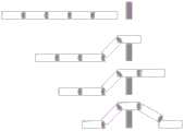
或者由所述的自组装模块化机器人单元对接系统对接组成若干多足机器人;自组装模块化机器人包括若干横向级联的自组装模块化机器人单元和若干纵向级联的自组装模块化机器人单元;横向级联时,自组装模块化机器人单元的左端和右端的被动对接模块级联若干纵向级联的自组装模块化机器人单元的前端的主动对接模块,纵向级联时,自组装模块化机器人单元通过后端的被动对接模块与其它纵向自组装模块化机器人单元主动对接模块纵向级联。Or several multi-legged robots are formed by docking with the self-assembling modular robot unit docking system; the self-assembling modular robot includes several horizontally cascaded self-assembling modular robot units and several vertically cascaded self-assembling modular robot units; When cascading horizontally, the passive docking modules at the left and right ends of the self-assembling modular robot unit cascade the active docking modules at the front end of several vertically cascading self-assembling modular robot units, and when cascading vertically, the self-assembling modular robot unit The passive docking module at the rear end is vertically cascaded with the active docking module of other longitudinal self-assembled modular robot units.
进一步地,每个横向、纵向级联的自组装模块化机器人单元在后端、或者左右两侧能够依次扩展纵向及横向级联的自组装模块化机器人单元。Further, each horizontally and vertically cascaded self-assembled modular robot unit can sequentially expand the vertically and horizontally cascaded self-assembled modular robot unit at the rear end, or on the left and right sides.
进一步地,通过控制机器人单元的关节驱动模块执行俯仰和偏航执行关节动作;通过控制机器人单元移动模块执行移动动作。Further, joint actions are performed by controlling the joint drive module of the robot unit to perform pitch and yaw; and movement actions are performed by controlling the movement module of the robot unit.
第三方面提供一种所述的自组装模块化机器人的自组装方法,包括:The third aspect provides a self-assembly method of the self-assembly modular robot, including:
在主动对接机器人单元与目标机器人单元之间规划一条轨迹,轨迹包括两段,第一段轨迹起始点为主动对接机器人单元的当前位姿,终点与目标机器人单元的被动对接模块偏航方向对齐,第一段轨迹为多项式曲线或者样条曲线,第二段轨迹以第一段轨迹终点为起始点,终点为目标机器人单元正后方一定距离,使得主动对接模块与被动对接模块能够执行夹持操作;Plan a trajectory between the active docking robot unit and the target robot unit. The trajectory includes two sections. The starting point of the first trajectory is the current pose of the active docking robot unit, and the end point is aligned with the yaw direction of the passive docking module of the target robot unit. The first trajectory is a polynomial curve or spline curve, the second trajectory starts from the end point of the first trajectory, and the end point is a certain distance directly behind the target robot unit, so that the active docking module and the passive docking module can perform clamping operations;
驱动夹持部打开,控制主动对接模块所在机器人单元移动使得所述夹持部包络突出部,驱动夹持部固定突出部,级联两个机器人单元。The clamping part is driven to open, the robot unit where the active docking module is located is controlled to move so that the clamping part envelops the protruding part, the clamping part is driven to fix the protruding part, and the two robot units are cascaded.
进一步地,其特征在于,主动对接机器人单元与目标机器人单元之间的定位包括:由所述远距离定位单元引导机器人单元移动至目标机器人后部可视距离内,识别目标机器人单元的编号与位置姿态,规划第一段、第二段轨迹,由中距离图像定位单元沿第一段轨迹引导至主动对接模块和被动对接模块偏航方向对齐,并沿第二段轨迹引导至对接位置使夹持部到达被动对接模块部位,由红外定位单元确认已经对准,控制进行对接。Further, it is characterized in that the positioning between the active docking robot unit and the target robot unit includes: the remote positioning unit guides the robot unit to move to within the visible distance behind the target robot, and identifies the number and position of the target robot unit Attitude, planning the first and second trajectories, guided by the mid-range image positioning unit along the first trajectory to align the yaw direction of the active docking module and the passive docking module, and guiding to the docking position along the second trajectory to enable clamping The first part reaches the position of the passive docking module, the infrared positioning unit confirms that it has been aligned, and controls the docking.
进一步地,级联的自组装模块化机器人单元选择一个控制模块作为主控制器,其它控制模块作为从控制器接收主控制器的指令,向主控制器反馈自身的位姿、速度信息,驱动各个自组装模块化机器人单元通过履带移动,或者执行关节驱动实现移动。Furthermore, the cascaded self-assembled modular robot unit selects one control module as the main controller, and other control modules receive instructions from the main controller as slave controllers, feed back their own pose and speed information to the main controller, and drive each Self-assembling modular robotic units move on tracks, or perform joint actuation to achieve locomotion.
进一步地,对于蛇形机器人执行关节驱动进行仿蛇蜿蜒或仿尺蠖/毛毛虫蠕动或者同时驱动移动模块移动;当遇到障碍时,驱动关节模块执行俯仰运动,抬起前方的自组装模块化机器人单元高于障碍,驱动移动模块移动通过障碍后,通过执行俯仰运动,回落至地面;或驱动关节模块执行偏航运动,越障过程中转向;Further, the snake robot performs joint drive to imitate snake winding or imitate inchworm/caterpillar wriggle or drive the mobile module to move at the same time; when encountering an obstacle, drive the joint module to perform pitching motion and lift the front self-assembled modular The robot unit is higher than the obstacle, drives the mobile module to move through the obstacle, and then falls back to the ground by performing a pitching motion; or drives the joint module to perform a yaw motion, and turns during the obstacle-crossing process;
对于多足机器人执行关节驱动执行关节驱动仿足移动;当遇到障碍时,驱动关节模块执行俯仰、偏航,抬起、摆动前方的自组装模块化机器人单元高于障碍,通过障碍后,通过执行俯仰、偏航,回落至地面。For multi-legged robots, perform joint drive to perform joint drive imitation foot movement; when encountering an obstacle, drive the joint module to perform pitch, yaw, lift, and swing the self-assembled modular robot unit in front of it higher than the obstacle. After passing the obstacle, pass Perform pitch, yaw, and return to the ground.
进一步地,当需要执行对目标物的操作时,驱动各个关节模块执行俯仰和/或偏航到达目标姿态,对目标进行包裹抓取。Further, when it is necessary to perform operations on the target, each joint module is driven to perform pitch and/or yaw to reach the target attitude, and grab the target for packages.
本发明的上述技术方案具有如下有益的技术效果:The technical solution of the present invention has the following beneficial technical effects:
(1)本发明提供的自组装模块化机器人单元可以自组装,通过感知、控制自主完成与其它机器人与物体的对接,对接后形成的组合体不仅具备整体移动能力还具备关节运动与操作能力,实现从轮式/履带到关节式的复合运动特性。从而可以克服群体机器人之间无连接或者连接弱的特点。(1) The self-assembled modular robot unit provided by the present invention can be self-assembled, and can autonomously complete the docking with other robots and objects through perception and control. Realize compound motion characteristics from wheeled/crawler to articulated. Thereby, the characteristics of no connection or weak connection between group robots can be overcome.
(2)本发明实现跨模式的运动,增加了组合体机器人的结构多样性,如构建成蛇形、多足等机器人形态,组装方式灵活多样,让单个机器人通过组合完成越障、搬运等高于自身能力的任务。(2) The present invention realizes cross-mode movement, which increases the structural diversity of the combined robot, such as building snake-like, multi-legged robot forms, flexible and diverse assembly methods, allowing a single robot to complete obstacle-crossing, handling, etc. tasks based on their own abilities.
(3)本发明自组装模块化机器人单元通过多种定位方法实现对自身的定位,在远距离时(距离目标0.5-1米以上)利用超宽带定位技术结合固定的基站实现0.1-1米精度的粗定位,在近距离(距离目标0.1-0.5米)时,利用摄像头结合姿态里程计信息测量目标标记实现0.05-0.2米精度的细定位;在贴近目标(距离目标0-0.1米)时,利用红外传感器实现0.005-0.02米的精细定位。通过三种定位手段相互结合,实现机器人从较远距离开始自主对接,使得自动对接成功率明显提高,扩展了的机器人的自动对接移动范围。(3) The self-assembled modular robot unit of the present invention realizes its own positioning through multiple positioning methods, and at a long distance (more than 0.5-1 meters from the target) utilizes ultra-wideband positioning technology combined with a fixed base station to achieve 0.1-1 meter accuracy Coarse positioning, at a short distance (0.1-0.5 meters from the target), use the camera combined with the attitude odometer information to measure the target mark to achieve fine positioning with an accuracy of 0.05-0.2 meters; when close to the target (0-0.1 meters from the target), Use the infrared sensor to achieve fine positioning of 0.005-0.02 meters. Through the combination of the three positioning methods, the robot can automatically dock from a relatively long distance, so that the success rate of automatic docking is significantly improved, and the automatic docking movement range of the robot is expanded.
(4)本发明的夹持部通过电机驱动开合,设置上下两个滑块进行承载力分解,利用夹持的方法提高对接的成功率,保证了机器人的稳定性和连接强度。(4) The clamping part of the present invention is driven by a motor to open and close, and two upper and lower sliders are set to decompose the bearing capacity, and the success rate of docking is improved by using the clamping method, which ensures the stability and connection strength of the robot.
(5)本发明的主动对接单元能够进行俯仰和偏航的控制,使得组装后的机器人能够执行关节运动;对于多足等机器人通过俯仰和偏航的控制实现足类移动;对接过程可动态调整主被动对接模块,提高地形适应性。(5) The active docking unit of the present invention can control pitch and yaw, so that the robot after assembly can perform joint motion; for robots such as multi-legged, the foot can be moved through the control of pitch and yaw; the docking process can be dynamically adjusted Active and passive docking modules improve terrain adaptability.
附图说明Description of drawings
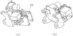
图1是群体移动自组装模块化机器人单元结构示意图;Figure 1 is a schematic diagram of the structure of a group mobile self-assembling modular robot unit;
图2是主动对接模块左前和左后视图以及滑块组成图;其中图2(a)为左前视图,图2(b)为左后视图,图2(c)为滑块组成图,图2(d)为安装滑轨后示意图,图2(e)为安装滑轨后另一角度视图;Figure 2 is the left front and left rear views of the active docking module and the composition diagram of the slider; where Figure 2(a) is the left front view, Figure 2(b) is the left rear view, Figure 2(c) is the slider composition diagram, Figure 2 (d) is a schematic diagram after installing the slide rail, and Fig. 2 (e) is another angle view after installing the slide rail;
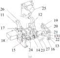
图3为主动对接模块示意图,其中图3(a)为主动对接模块爆炸视图,图3(b)为主动对接模块夹持传动示意图,图3(c)为主动对接模块侧向视图;Figure 3 is a schematic diagram of the active docking module, wherein Figure 3(a) is an exploded view of the active docking module, Figure 3(b) is a schematic diagram of the clamping and transmission of the active docking module, and Figure 3(c) is a side view of the active docking module;
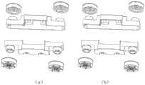
图4为被动对接模块图及对接锥/槽对应图;其中,图4(a)为被动对接模块示意图;图4(b)为对接锥/槽对应图;Fig. 4 is a diagram of a passive docking module and a corresponding diagram of a docking cone/groove; wherein, Fig. 4 (a) is a schematic diagram of a passive docking module; Fig. 4 (b) is a corresponding diagram of a docking cone/groove;
图5为关节驱动模块图;其中图5(a)为偏航、俯仰复合动作侧向视图,Figure 5 is a diagram of the joint drive module; Figure 5(a) is a side view of the yaw and pitch compound action,
图5(b)为偏航动作俯视图,图5(c)为俯仰动作示意图;Figure 5(b) is a top view of the yaw action, and Figure 5(c) is a schematic diagram of the pitch action;
图6为移动模块、车架与感知驱动控制系统组成图;Figure 6 is a composition diagram of the mobile module, frame and perception drive control system;
图7为轮子移动模块组成图,其中图7(a)为四轮驱动移动模块图,图7(b)为两轮差速驱动移动模块图,图7(c)为麦克纳姆轮全向移动模块图;Figure 7 is a composition diagram of the wheel mobile module, where Figure 7(a) is a four-wheel drive mobile module diagram, Figure 7(b) is a two-wheel differential drive mobile module diagram, and Figure 7(c) is a mecanum wheel omnidirectional Mobile block diagram;
图8为移动模块化机器人单元利用传感器自主对接框架图;Fig. 8 is a frame diagram of the autonomous docking of the mobile modular robot unit using sensors;
图9为移动模块化机器人单元组成蛇形机器人;Figure 9 is a snake-like robot composed of mobile modular robot units;
图10为移动模块化机器人单元组成四足机器人;Figure 10 is a quadruped robot composed of mobile modular robot units;
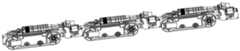
图11为移动模块化机器人单元组成八足机器人;Figure 11 is an eight-legged robot composed of mobile modular robot units;
图12为蛇形机器人控制越障示意图;Fig. 12 is a schematic diagram of snake-like robot control over obstacles;
图13为蛇形机器人控制爬楼梯示意图。Fig. 13 is a schematic diagram of a snake-like robot controlled to climb stairs.
具体实施方式Detailed ways
为使本发明的目的、技术方案和优点更加清楚明了,下面结合具体实施方式并参照附图,对本发明进一步详细说明。应该理解,这些描述只是示例性的,而并非要限制本发明的范围。此外,在以下说明中,省略了对公知结构和技术的描述,以避免不必要地混淆本发明的概念。In order to make the object, technical solution and advantages of the present invention clearer, the present invention will be further described in detail below in combination with specific embodiments and with reference to the accompanying drawings. It should be understood that these descriptions are exemplary only, and are not intended to limit the scope of the present invention. Also, in the following description, descriptions of well-known structures and techniques are omitted to avoid unnecessarily obscuring the concept of the present invention.
本发明的目的在于提供一种自组装模块化机器人单元及其形成的群体移动自组装模块化机器人,以解决现有技术中存在的群体机器人形成的可变结构少、自动对接能力弱以及连接后不具备关节运动能力等问题。The purpose of the present invention is to provide a self-assembling modular robot unit and the group mobile self-assembling modular robot formed by it, so as to solve the problems in the prior art that the group robot forms less variable structures, weak automatic docking ability and poor connection after connection. Does not have problems such as joint movement ability.
自组装模块化机器人由一组模块化机器人单元组成,每个模块化机器人单元具备移动能力,任意两个移动模块化机器人可以通过自主移动利用对接系统形成级联的组合体,组合体之间可以通过关节进行运动,也可以共同移动。The self-assembling modular robot is composed of a group of modular robot units, and each modular robot unit has the ability to move. Any two mobile modular robots can form a cascaded combination by using the docking system through autonomous movement. Movement is performed through the joints, which can also move together.
自组装模块化机器人单元通过前后首尾相连接,可以形成具备移动能力和关节运动能力的蛇形机器人。一组模块化机器人单元连接到另一组模块化机器人单元的左右两侧或者尾部,可以形成仿生多足关节机器人。The self-assembling modular robotic units can be connected end-to-end to form a snake-like robot with locomotion and articulation capabilities. A group of modular robot units is connected to the left and right sides or the tail of another group of modular robot units to form a bionic multi-leg joint robot.
自组装模块化机器人单元利用摄像头、红外传感器自主感知测量其它的机器人(目标)的编号,并且确定目标的位置和姿态。各个群体移动自组装模块化机器人单元相互之间以及与外部的通信基站可以组成无线网络,一组机器人单元形成一个子网,具备一个协调器,另一组机器人单元形成另一个子网,具备一个协调器,各个协调器形成另一个网络,典型通信协议为ZigBee。The self-assembled modular robot unit uses cameras and infrared sensors to autonomously perceive and measure the numbers of other robots (targets), and determine the position and posture of the targets. Each group of mobile self-assembled modular robot units can form a wireless network with each other and with external communication base stations. A group of robot units forms a subnet with a coordinator, and another group of robot units forms another subnet with a Coordinator, each coordinator forms another network, and the typical communication protocol is ZigBee.
自组装模块化机器人单元具有不同精度和距离的定位系统,实现远、中、近距离的目标定位。在远距离时(距离目标0.5-1米以上)利用超宽带定位技术结合固定的基站实现0.1-1米精度的粗定位,在近距离(距离目标0.1-0.5米)时,利用摄像头结合姿态里程计信息测量目标标记实现0.05-0.2米精度的细定位;在贴近目标(距离目标0-0.1米)时,利用红外传感器实现0.005-0.02米的精细定位。The self-assembling modular robotic unit has a positioning system with different accuracy and distance to achieve long-, medium-, and short-range target positioning. At a long distance (more than 0.5-1 meters from the target), use ultra-wideband positioning technology combined with a fixed base station to achieve rough positioning with an accuracy of 0.1-1 meters; Measuring information to measure target marks to achieve fine positioning with an accuracy of 0.05-0.2 meters; when close to the target (0-0.1 meters away from the target), use infrared sensors to achieve fine positioning at 0.005-0.02 meters.
自组装模块化机器人单元包括主动对接模块1以及被动对接模块2。自组装模块化机器人单元还包括关节驱动模块3、移动模块4、定位模块5及车架6。主动对接模块1位于车架6的前方,被动对接模块2位于车架6的后方或者左右两侧,关节驱动模块3的输出端连接到主动对接模块1,固定端连接到车架6。移动模块4位于车架6的左右两侧。The self-assembled modular robot unit includes an
主动对接模块1,包括连接架11、第一滑块组12、第一对接板13、第二滑块组14、第二对接板15、对接锥16、电机固定架17、电机18、第一传动组件19、第二传动组件20、第三传动组件21、螺杆22、第一螺母23和第二螺母24、摄像头模块25、连接轴26和红外接收面板27,如图2和图3所示。连接架11具有左右两侧的连杆,连杆上部的端点有两个连接孔111,下部有两个连接孔112,连接轴26连接到连接孔111上。第一滑块组12的滑块121沿滑轨122滑动,滑轨122固定在连接架11的凸块114上面。第二滑块组14的滑块141沿滑轨142滑动,滑轨142固定在连接架11的凸块114下面。第一对接板13连接到滑块121上,第二对接板15连接到滑块141上。对接锥16安装在第一对接板13和第二对接板15上,每个对接板至少包括1个对接锥16,一个主动对接模块至少包括3个对接锥16,典型为左右镜面对称分布各2个对接锥16。电机18输出轴驱动第一传动组件19,第一传动组件19、第二传动组件20、第二传动组件21啮合形成传动组件,结合图3(c),其旋转支撑轴固定到连接架11的传动固定架113上。第三传动组件21和螺杆22同步传动,螺杆22通过轴承安装在传动固定架113上。电机18通过电机固定架12连接到支架11上,电机18输出轴直接与第一传动组件19同轴相连并且驱动旋转,依次传动第二传动组件20、第二传动组件21,最终驱动螺杆22转动,螺杆的左右螺纹为相反旋向,从而驱动螺母23和24向相反方向沿螺杆22直线运动,螺杆22的左右螺纹为相反旋向。螺母23和24分别与第一对接板13和第二对接板15连接,第一对接板13和第二对接板15分别连接到第一滑块组12的滑块121和第二滑块组14的滑块141,限制了螺母23和24的旋转,并由上下两个滑块组共同提供对接后级联机器人之间力的传递与支撑。在仅可平行左右直线移动的约束下,第一对接板13和第二对接板15分别向相反方向沿螺杆22直线运动。安装到螺杆上的螺母23和24的旋向相反,保证在螺杆22驱动下反方向运动。通过该对接模块,连接板可对称打开和闭环,从而可与被动对接模块配合完成两个机器人之间的刚性连接。螺杆螺母机构实现开合,传动具有自锁能力。第一滑块组12和第二滑块组14可提高对接机构的连接刚度和强度。电机18通过伺服闭环控制,可控制连接板打开和闭环的大小。传动固定架113左右两部分的距离h为开合最小距离,螺杆22、导轨122和142中最小距离为开合最大距离,该距离范围为允许对接的结构误差。对接锥16为圆锥形状,与被动对接机构模块2的对接槽结构配合,如果对接锥16已经插入对接槽28,但在主被动对接模块与被动对接模块没有完全对准时,锥角可让两个机器人在电机18驱动力的引导下使两个对接模块完成对接。摄像头模块25连接到连接架11上,镜头向前,可以感知识别视觉标记28和其它物体,内部集成专用图像处理电路。红外接收面板27连接到连接架11上,上面分布有水平一线布局的红外接收管。The
被动对接模块2包括对接槽28、视觉标记29和红外发射管30,如图4所示。对接槽28和对接锥16在数量、布局上相同。视觉标记29具有编码功能,代表该移动模块化机器人的编号,典型的编码方式为二维码或者色块,可以通过摄像头模块25识别后测量出其相对位置和姿态。红外发射管30发射一束红外光,主动对接模块1上的红外接收面板27上分布的某个红外接收管接收该红外光,表示发射接收对齐,主动对接模块1与被动对接模块2对齐。The
主动对接模块1和被动对接模块2各设置有一组触点131和211,当对接机构闭合时,触点接通,可实现对接两模块机器人之间的动力电源及通讯信号的连通,以便模块间有线通讯。The
关节驱动模块3包括支撑架31、第一球铰32、第一直线电机33、第二直线电机34、第二球铰35、偏航固定板36、俯仰固定板37、偏航连接轴38、俯仰连接轴39组成,如图5a。支撑架31固定到车架6上。第一直线电机33、第二直线电机34分别通过第一球铰32连接到支撑架31上,连接点的偏航和俯仰自由度不被约束固定,可被动运动。第一直线电机33、第二直线电机34通过第二球铰35连接到连接架11的连接轴26上,连接点的偏航和俯仰自由度不被约束固定,可被动运动。主动对接模块1的连接架11通过俯仰连接轴39与俯仰固定板37相连,可相对进行被动的俯仰运动,俯仰固定板37相连通过偏航连接轴38与偏航固定板36相连,可相对进行被动的偏航运动,偏航固定板36连接到车架6上。当第一直线电机33与第二直线电机34中一个伸长同时另一个缩短相同距离时,主动对接机构1相对车架6偏航一定角度a,如图5b。第一直线电机33、第二直线电机34可分别控制长度,当同时伸长或者缩短相同距离时,主动对接机构1相对车架6俯仰一定角度b,如图5c。分别控制第一直线电机33、第二直线电机34的长度,实现主动对接机构1相对车架6偏航、俯仰一定角度。平衡状态下,主动对接机构1相对车架6偏航、俯仰角度为0,偏航固定板36与偏航连接轴38相交点距离直线电机中轴的距离为l,两个直线电机的距离为d,第一球铰32和第一球铰35之间的水平距离为l。第一直线电机33、第二直线电机34的行程以及l、c和d影响偏航角度a、俯仰角度b的范围以及主动电机驱动对接机构的传动比。利用直线电机推杆的方式可以提高关节的驱动力矩,从而提升多个模块化机器人连接在一起时的运动性能。The
调整偏航、俯仰角度也可在机器人底座不平时,使得对接前两个机器人单元的主动对接模块和被动对接模块的对接锥与对接槽轴线重合,如图4(b)所示。Adjusting the yaw and pitch angles can also be done when the robot base is uneven, so that the docking cones of the active docking module and the passive docking module of the two robot units before docking coincide with the axes of the docking slot, as shown in Figure 4(b).
移动模块4具备地面移动能力,由一组履带移动模块或者轮子驱动模块组成,如图6所示。履带驱动模块包括左右两个平行的履带;或者轮子驱动模块,包括前后各两个轮子的四驱、两轮差分驱动或者四个轮子为麦克纳姆轮的驱动移动方式。The
履带移动模块4包括第一驱动轮毂41、第二驱动轮毂42、第三驱动轮毂43、第四驱动轮毂44、第一驱动电机45、第二驱动电机46、张紧轮47、第一履带48、第二履带49。驱动轮毂左右各两个为一组,前后布局连接到车架,驱动一条履带。张紧轮连接在车架,通过偏离压紧履带,并跟随履带自动旋转。至少两个驱动电机,一个驱动左侧的一个驱动轮毂,另一个驱动右侧的一个驱动轮毂,为减小移动模块化机器人横向尺寸,两个驱动电机前后布局,分别驱动前面和后面的各一个驱动轮毂。履带为环状,外表面局部凹凸的槽增加摩擦力,内部通过钢丝纤维环增强耐疲劳程度。一个实例,第一驱动轮毂41、第二驱动轮毂42前后布局,分布在车架6的右侧,支撑驱动第一履带48。同样,第三驱动轮毂43、第四驱动轮毂44前后布局,分布在车架6的左侧,支撑驱动第二履带49。右侧张紧轮47的固定端连接到车架6上,通过调整位置形成对第一履带48的张紧力。左侧类似。第一驱动电机45驱动第一驱动轮毂41,第二驱动电机46驱动第三驱动轮毂43。驱动电机集成减速器、马达、编码器以及驱动控制器,通过位置及速度闭环精确控制左右两侧履带的旋转速度。驱动轮毂分别安装在车架6左右两侧的轮毂安装轴611上。The track
轮子驱动模块,前后各两个轮子的四驱形式为前后左右布置一个驱动电机,分别驱动四个驱动轮毂运动,每个驱动轮毂外装轮胎,如图7a。两轮差分驱动形式为后面两个驱动电机驱动两个后面的轮子,而前面两个轮子为被动轮,同样,也可以前面两个驱动电机驱动两个前面的轮子,而后面两个轮子为被动轮,如图7b。麦克纳姆轮的驱动移动方式为前后左右布置一个驱动电机,分别驱动四个驱动轮毂运动,每个驱动轮毂外装轮胎,可以形成平面完整运动的系统,如图7c。For the wheel drive module, the four-wheel drive form of two wheels at the front and rear is that a drive motor is arranged at the front, rear, left, and right to drive the four drive hubs respectively, and each drive hub is equipped with tires, as shown in Figure 7a. The form of two-wheel differential drive is that the two rear driving motors drive the two rear wheels, while the front two wheels are passive wheels. Similarly, the two front driving motors can also drive the two front wheels, while the rear two wheels are passive. wheel, as shown in Figure 7b. The driving and moving mode of the mecanum wheel is to arrange a driving motor at the front, rear, left, and right to drive the four driving hubs respectively, and each driving hub is equipped with tires, which can form a planar complete motion system, as shown in Figure 7c.
定位模块5系统包括无线通信系统52、远距离定位单元53(无线定位系统)、中距离图像定位单元、近距离红外定位单元等。中距离图像定位单元包括摄像头模块25和姿态感知模块54,近距离红外定位单元包括红外接收面板27和红外发生管30。无线通信系统52采用Zigee、Lora或者NBIoT等物联网协议,除机器人自身的无线通信系统外,在其它地方可以安装通信的协调器和路由器,各个机器人通过该通信系统以及其它的协调器、路由器组成网状拓扑的通信网络;无线定位系统53采用超宽带定位UWB方法,在应用场地外安装3个以上的参考基站,来确定各个机器人相对基站的位置;姿态感知模块54采用陀螺仪、加速度计和磁强计通过滤波器形成的惯性传感系统,控制模块,包括控制器,还可以包括图像传输模块,将摄像头数据无线传输到外部接收点,还包括温湿度等传感器来增加模块化机器人的功能。控制模块的主控制器51与无线通信系统52、无线定位系统53、姿态感知模块54进行串行通信,与轮毂电机、对接电机与关节驱动模块的控制系统进行通信,与主动对接模块的电机的驱动器进行通信控制,与摄像头模块进行通信,获取识别的编号和目标位姿信息等。机器人单元由锂电池55供电。The
自组装模块化机器人单元通过多种定位方法实现对主动对接模块化机器人单元相对被动对接的移动模块化机器人单元的定位,首先接收到无线通信信号,采用ZigBee、Lora、NBIoT等无线信号,在较远距离获得被动对接的移动模块化机器人(目标)的编号以及粗略位置(0.1-0.5米精度误差),该粗略位置为各个机器人内部无线定位系统测量出自身相对基站的位置;主动对接机器人运动到目标对接机器人后部较近距离,通过摄像头模块25寻找到被动对接模块2上的视觉标记29,识别编号和初步的位置姿态作为目标,首先通过摄像头模块和自身姿态里程计融合后获得估计的定位信息,融合方法包括利用摄像头识别视觉标记获得的绝对位姿与机器人编码器/姿态里程计获得的相对位姿进行滤波(卡尔曼滤波器、贝叶斯估计、蒙特卡洛法或者粒子滤波器),主动对接移动模块化机器人通过移动模块3运动到被动对接移动模块化机器人纵轴中心线上(第一阶段),实现两个机器人在水平面朝向的偏航角度对齐,然后主动对接移动模块化机器人在摄像头模块和自身姿态的引导下沿直线运动到被动对接移动模块化机器人的被动对接模块2处,完成主动对接模块1与被动对接模块2的对齐,对接锥16与对接槽28配合,完成两个移动模块化机器人的连接,如图8所示。The self-assembled modular robot unit realizes the positioning of the active docking modular robot unit relative to the passive docking mobile modular robot unit through a variety of positioning methods. Obtain the number and rough position (0.1-0.5 meter accuracy error) of the passively docked mobile modular robot (target) at a long distance. The rough position is the position of each robot relative to the base station measured by the internal wireless positioning system; the active docking robot moves to The target is docked at a relatively short distance from the rear of the robot, and the
车架6包括左右对称的第一车体61、第二车体62和底板63,三者刚性连接。被动对接模块3连接到第一车体61和第二车体62的尾部固定或者连接到左右两侧。关节驱动模块3连接到第一车体61和第二车体62的上部固定。关节驱动模块3的偏航固定板36连接到第一车体61和第二车体62的前部固定。The
被动对接模块2位于车架6尾部时,移动模块化机器人通过主动对接模块1与被动对接模块2的连接,前后首尾相连接,形成具备移动能力和关节运动能力的蛇形机器人,如图9所示。When the
被动对接模块3位于车架6尾部以及车体61和62左右两侧时,移动模块化机器人通过主动对接模块1与被动对接模块2的连接,一组移动模块化机器人连接到另一组移动模块化机器人的左右两侧,可以形成仿生四足关节机器人,如图10所示,或者八足关节机器人,如图11所示,或者其它仿生多足机器人。When the
本发明提供一种所述的自组装模块化机器人的自组装方法,包括规划、定位与控制。规划部分为在主动对接机器人单元与目标机器人单元之间规划一条轨迹,两段组成,第一段轨迹起始点为主动对接机器人单元的当前位姿,终点为使得主动对接模块和被动对接模块偏航方向对齐,此轨迹可为多项式曲线或者样条曲线,多项式曲线采用
自组装模块化机器人控制方法,包括:在模块化机器人单元级联后形成的整体的自组装模块化机器人控制时,选用其中一个模块化机器人单元作为主控制器,负责算法、任务及系统处理,利用无线通信系统或者级联对接时的有线总线(RS485、CAN等)来与其它级联的模块化机器人单元通信,控制各个模块化机器人单元执行移动动作、关节动作,并采集传感器等信息。The self-assembling modular robot control method includes: when the overall self-assembling modular robot control is formed after the modular robot units are cascaded, one of the modular robot units is selected as the main controller, which is responsible for algorithms, tasks and system processing, Use the wireless communication system or the wired bus (RS485, CAN, etc.) during cascade docking to communicate with other cascaded modular robot units, control each modular robot unit to perform movement actions, joint actions, and collect information such as sensors.
自组装模块化机器人在运动过程中既可以利用移动动作前行,实现整体前进/后退、转向;也可以结合关节运动前行,通过关节运动抬实现越障和翻越。执行关节动作可以控制级联的部分模块化机器人单元作为移动的腿,也可以控制级联的部分模块化机器人单元作为操作物体、抓取物体的臂、或者手,以及作为颈部定位摄像头等模块。级联形成蛇形机器人时,若干模块化机器人分布于平面运动区,与外部基站进行无线通信(ZigBee)。根据指令自动组装形成蛇形机器人。蛇形机器人通过履带行走,或者执行关节驱动进行仿蛇蜿蜒、仿尺蠖/毛毛虫蠕动。如若遇到障碍,利用俯仰关节以此抬起前方模块化机器人单元高于障碍,然后前行移动,使得位于障碍上方的模块化机器人单元与障碍上面接触,同时执行移动动作,越过障碍后,利用俯仰关节落下前方模块化机器人单元到地面,执行移动动作,依次通过障碍,如图12所示。蛇形机器人通过移动动作和关节动作组合越过楼梯,通过楼梯的方法为,当模块化机器人单元头部接触到楼梯时,第1个俯仰关节抬起,使得前部机身与楼梯斜面平行,再继续移动前行时,第2个和第1个俯仰关节配合,使前部机身与楼梯斜面平行,依次类推,直到整个机器人穿过楼梯,在楼梯对此,反序依次控制,如图13所示。The self-assembled modular robot can not only use the moving action to move forward, realize the overall forward/reverse, turn, but also combine the joint movement to move forward, and realize the obstacle and overturning through the joint movement. Executing joint actions can control cascades of partially modular robotic units as moving legs, and can also control cascades of partially modular robotic units as arms for manipulating objects, grasping objects, or hands, and as necks to position modules such as cameras . When cascading to form a snake-like robot, several modular robots are distributed in the plane movement area and communicate with external base stations wirelessly (ZigBee). According to the instructions, it is automatically assembled to form a snake-like robot. Snake robots walk on crawler tracks, or perform joint drives to snake-like snakes and inchworms/caterpillars to wriggle. If you encounter an obstacle, use the pitch joint to lift the front modular robot unit higher than the obstacle, and then move forward, so that the modular robot unit above the obstacle is in contact with the obstacle, and at the same time perform the movement action. After crossing the obstacle, use The pitch joint drops the front modular robot unit to the ground, performs movement actions, and passes obstacles in turn, as shown in Figure 12. The snake-like robot crosses the stairs through a combination of movement and joint actions. The way to pass the stairs is that when the head of the modular robot unit touches the stairs, the first pitch joint is lifted so that the front body is parallel to the slope of the stairs, and then When continuing to move forward, the second and first pitch joints cooperate to make the front body parallel to the slope of the stairs, and so on until the whole robot passes through the stairs. On the stairs, it is controlled in reverse order, as shown in Figure 13 shown.
级联形成多组机器人,使得与地面接触的模块化机器人单元执行移动动作,在地面移动,在遇到障碍时,执行关节动作可以抬起各个纵向级联的模块化机器人单元,翻越爬行。Cascade to form multiple groups of robots, so that the modular robot units in contact with the ground perform movement actions, move on the ground, and when encountering obstacles, perform joint actions to lift each longitudinally cascaded modular robot unit to climb over and crawl.
综上所述,本发明涉及一种自组装模块化机器人单元、机器人、组装及控制方法,通过提供的自组装模块化机器人单元可以自组装,通过感知、控制自主完成与其它机器人与物体的对接,对接后形成的组合体不仅具备整体移动能力还具备关节运动与操作能力,实现从轮式/履带到关节式的复合运动特性。从而可以克服群体机器人之间无连接或者连接弱的特点,实现跨模式的运动,也增加了组合体机器人的结构多样性,如构建成蛇形、多足等机器人形态,组装方式灵活多样,让单个机器人通过组合完成越障、搬运等高于自身能力的任务。In summary, the present invention relates to a self-assembled modular robot unit, a robot, an assembly and a control method, through which the self-assembled modular robot unit can be self-assembled, and the docking with other robots and objects can be completed autonomously through perception and control , the combination formed after docking not only has the overall movement ability but also has joint motion and operation ability, realizing the compound motion characteristics from wheel/track to joint type. In this way, it can overcome the characteristics of no connection or weak connection between group robots, realize cross-mode movement, and increase the structural diversity of combined robots, such as building snake-shaped robots, multi-legged robot forms, etc. A single robot completes tasks higher than its own capabilities, such as overcoming obstacles and handling, through combination.
应当理解的是,本发明的上述具体实施方式仅仅用于示例性说明或解释本发明的原理,而不构成对本发明的限制。因此,在不偏离本发明的精神和范围的情况下所做的任何修改、等同替换、改进等,均应包含在本发明的保护范围之内。此外,本发明所附权利要求旨在涵盖落入所附权利要求范围和边界、或者这种范围和边界的等同形式内的全部变化和修改例。It should be understood that the above specific embodiments of the present invention are only used to illustrate or explain the principle of the present invention, and not to limit the present invention. Therefore, any modification, equivalent replacement, improvement, etc. made without departing from the spirit and scope of the present invention shall fall within the protection scope of the present invention. Furthermore, it is intended that the appended claims of the present invention embrace all changes and modifications that come within the scope and metesques of the appended claims, or equivalents of such scope and metes and bounds.
Claims (9)
Priority Applications (1)
| Application Number | Priority Date | Filing Date | Title |
|---|---|---|---|
| CN202110082466.0ACN112873188B (en) | 2021-01-21 | 2021-01-21 | Self-assembled modular robot unit, robot, assembly and control method |
Applications Claiming Priority (1)
| Application Number | Priority Date | Filing Date | Title |
|---|---|---|---|
| CN202110082466.0ACN112873188B (en) | 2021-01-21 | 2021-01-21 | Self-assembled modular robot unit, robot, assembly and control method |
Publications (2)
| Publication Number | Publication Date |
|---|---|
| CN112873188A CN112873188A (en) | 2021-06-01 |
| CN112873188Btrue CN112873188B (en) | 2023-05-12 |
Family
ID=76051507
Family Applications (1)
| Application Number | Title | Priority Date | Filing Date |
|---|---|---|---|
| CN202110082466.0AActiveCN112873188B (en) | 2021-01-21 | 2021-01-21 | Self-assembled modular robot unit, robot, assembly and control method |
Country Status (1)
| Country | Link |
|---|---|
| CN (1) | CN112873188B (en) |
Families Citing this family (3)
| Publication number | Priority date | Publication date | Assignee | Title |
|---|---|---|---|---|
| CN113335399B (en)* | 2021-06-17 | 2022-04-12 | 仁安建设科技集团有限公司 | Tank type fire engine actuating mechanism |
| CN113641174A (en)* | 2021-08-09 | 2021-11-12 | 山东大学 | An autonomous docking control method for a skid-steer modular robot |
| CN114347076B (en)* | 2021-12-06 | 2024-02-23 | 北京邮电大学 | Multifunctional end effector of continuous mechanical arm |
Citations (5)
| Publication number | Priority date | Publication date | Assignee | Title |
|---|---|---|---|---|
| GB201501479D0 (en)* | 2015-01-29 | 2015-03-18 | Norwegian Univ Sci & Tech Ntnu | Underwater manipulator arm robot |
| CN204935672U (en)* | 2015-09-11 | 2016-01-06 | 滨州学院 | A kind of snake-shaped robot joint and snake-shaped robot |
| CN205131418U (en)* | 2015-11-17 | 2016-04-06 | 深圳市博铭维智能科技有限公司 | Snakelike amphibious robot |
| CN110154008A (en)* | 2019-06-12 | 2019-08-23 | 杭星辰 | Snakelike/quadruped robot based on mimicry |
| CN111390888A (en)* | 2020-04-20 | 2020-07-10 | 河南科技大学 | Double-drive type modular snake-shaped robot based on multi-sensor fusion and driving method |
Family Cites Families (1)
| Publication number | Priority date | Publication date | Assignee | Title |
|---|---|---|---|---|
| US11155326B2 (en)* | 2019-03-29 | 2021-10-26 | The Hong Kong Polytechnic University | Bio-inspired underwater robot |
- 2021
- 2021-01-21CNCN202110082466.0Apatent/CN112873188B/enactiveActive
Patent Citations (5)
| Publication number | Priority date | Publication date | Assignee | Title |
|---|---|---|---|---|
| GB201501479D0 (en)* | 2015-01-29 | 2015-03-18 | Norwegian Univ Sci & Tech Ntnu | Underwater manipulator arm robot |
| CN204935672U (en)* | 2015-09-11 | 2016-01-06 | 滨州学院 | A kind of snake-shaped robot joint and snake-shaped robot |
| CN205131418U (en)* | 2015-11-17 | 2016-04-06 | 深圳市博铭维智能科技有限公司 | Snakelike amphibious robot |
| CN110154008A (en)* | 2019-06-12 | 2019-08-23 | 杭星辰 | Snakelike/quadruped robot based on mimicry |
| CN111390888A (en)* | 2020-04-20 | 2020-07-10 | 河南科技大学 | Double-drive type modular snake-shaped robot based on multi-sensor fusion and driving method |
Non-Patent Citations (2)
| Title |
|---|
| 攀爬蛇形机器人越障静态机理研究;程前等;机械设计与制造(第3期);37-40页* |
| 曹琳琳等.机器人编程设计与实现.华中科技大学出版社,2017,160-161页.* |
Also Published As
| Publication number | Publication date |
|---|---|
| CN112873188A (en) | 2021-06-01 |
Similar Documents
| Publication | Publication Date | Title |
|---|---|---|
| CN112873188B (en) | Self-assembled modular robot unit, robot, assembly and control method | |
| CN112873189B (en) | Self-assembly modular robot unit docking system and docking method | |
| EP2549165B1 (en) | Serpentine robotic crawler | |
| US8393422B1 (en) | Serpentine robotic crawler | |
| US8042630B2 (en) | Serpentine robotic crawler | |
| US7946372B2 (en) | Dual tracked mobile robot for motion in rough terrain | |
| CN101927488B (en) | Self-assembly multiple-mobile-robot system and self-assembly structure | |
| Hayat et al. | Panthera: Design of a reconfigurable pavement sweeping robot | |
| JPH08305440A (en) | Control device and method for motion control of a normal wheel type omnidirectional mobile robot | |
| CN115061469A (en) | Variable-wheelbase composite motion platform, intelligent unmanned system and motion control method thereof | |
| Singh et al. | Design and motion analysis of compliant omnidirectional spherical modular snake robot (COSMOS) | |
| Singh et al. | Design and implementation of Omni-directional spherical modular snake robot (OSMOS) | |
| Liu et al. | Autonomous control of an electric wheel-foot robotic system based on stewart structure | |
| Dai et al. | SWheg: A Wheel-Leg Transformable Robot With Minimalist Actuator Realization | |
| Duan et al. | Kinematic modeling of a small mobile robot with multi-locomotion modes | |
| Duan et al. | MOBIT, a small wheel-track-leg mobile robot | |
| Nesnas et al. | Autonomous vision-based manipulation from a rover platform | |
| CN119975586B (en) | Electromagnetic adsorption type multi-configuration switching wall climbing robot and inspection control system | |
| CN113043256A (en) | Snakelike joint crawler-type composite robot | |
| Wang et al. | Design and realization of a novel reconfigurable robot with serial and parallel mechanisms | |
| CN215883635U (en) | Walking vehicle for brick paving robot | |
| Kanazawa et al. | Obstacle-aware Autonomous Flipper Control Method Based on Terrain Geometry | |
| Fang et al. | Design and study of a forearm-type wheel-legged obstacle-crossing robot | |
| Shi et al. | Design and Analysis of a Self-Locking Passive Transformable Wheel Mobile Robot for Enhanced Mobility | |
| CN116330271A (en) | A control method for a snake-like robot |
Legal Events
| Date | Code | Title | Description |
|---|---|---|---|
| PB01 | Publication | ||
| PB01 | Publication | ||
| SE01 | Entry into force of request for substantive examination | ||
| SE01 | Entry into force of request for substantive examination | ||
| TA01 | Transfer of patent application right | Effective date of registration:20220907 Address after:10 Xitucheng Road, Haidian District, Beijing 100082 Applicant after:Beijing University of Posts and Telecommunications Applicant after:BEIHANG University Address before:10 Xitucheng Road, Haidian District, Beijing 100082 Applicant before:Beijing University of Posts and Telecommunications | |
| TA01 | Transfer of patent application right | ||
| GR01 | Patent grant | ||
| GR01 | Patent grant |