CN112870486B - Flow sensor system with absorber - Google Patents
Flow sensor system with absorberDownload PDFInfo
- Publication number
- CN112870486B CN112870486BCN202110039602.8ACN202110039602ACN112870486BCN 112870486 BCN112870486 BCN 112870486BCN 202110039602 ACN202110039602 ACN 202110039602ACN 112870486 BCN112870486 BCN 112870486B
- Authority
- CN
- China
- Prior art keywords
- flow
- flow sensor
- flow tube
- subassembly
- tube
- Prior art date
- Legal status (The legal status is an assumption and is not a legal conclusion. Google has not performed a legal analysis and makes no representation as to the accuracy of the status listed.)
- Active
Links
Images


Classifications
- A—HUMAN NECESSITIES
- A61—MEDICAL OR VETERINARY SCIENCE; HYGIENE
- A61M—DEVICES FOR INTRODUCING MEDIA INTO, OR ONTO, THE BODY; DEVICES FOR TRANSDUCING BODY MEDIA OR FOR TAKING MEDIA FROM THE BODY; DEVICES FOR PRODUCING OR ENDING SLEEP OR STUPOR
- A61M5/00—Devices for bringing media into the body in a subcutaneous, intra-vascular or intramuscular way; Accessories therefor, e.g. filling or cleaning devices, arm-rests
- A61M5/14—Infusion devices, e.g. infusing by gravity; Blood infusion; Accessories therefor
- A61M5/168—Means for controlling media flow to the body or for metering media to the body, e.g. drip meters, counters ; Monitoring media flow to the body
- A61M5/16804—Flow controllers
- A—HUMAN NECESSITIES
- A61—MEDICAL OR VETERINARY SCIENCE; HYGIENE
- A61M—DEVICES FOR INTRODUCING MEDIA INTO, OR ONTO, THE BODY; DEVICES FOR TRANSDUCING BODY MEDIA OR FOR TAKING MEDIA FROM THE BODY; DEVICES FOR PRODUCING OR ENDING SLEEP OR STUPOR
- A61M5/00—Devices for bringing media into the body in a subcutaneous, intra-vascular or intramuscular way; Accessories therefor, e.g. filling or cleaning devices, arm-rests
- A61M5/14—Infusion devices, e.g. infusing by gravity; Blood infusion; Accessories therefor
- A61M5/168—Means for controlling media flow to the body or for metering media to the body, e.g. drip meters, counters ; Monitoring media flow to the body
- A61M5/172—Means for controlling media flow to the body or for metering media to the body, e.g. drip meters, counters ; Monitoring media flow to the body electrical or electronic
- G—PHYSICS
- G01—MEASURING; TESTING
- G01F—MEASURING VOLUME, VOLUME FLOW, MASS FLOW OR LIQUID LEVEL; METERING BY VOLUME
- G01F1/00—Measuring the volume flow or mass flow of fluid or fluent solid material wherein the fluid passes through a meter in a continuous flow
- G01F1/56—Measuring the volume flow or mass flow of fluid or fluent solid material wherein the fluid passes through a meter in a continuous flow by using electric or magnetic effects
- G—PHYSICS
- G01—MEASURING; TESTING
- G01F—MEASURING VOLUME, VOLUME FLOW, MASS FLOW OR LIQUID LEVEL; METERING BY VOLUME
- G01F1/00—Measuring the volume flow or mass flow of fluid or fluent solid material wherein the fluid passes through a meter in a continuous flow
- G01F1/66—Measuring the volume flow or mass flow of fluid or fluent solid material wherein the fluid passes through a meter in a continuous flow by measuring frequency, phase shift or propagation time of electromagnetic or other waves, e.g. using ultrasonic flowmeters
- G01F1/662—Constructional details
- G—PHYSICS
- G01—MEASURING; TESTING
- G01F—MEASURING VOLUME, VOLUME FLOW, MASS FLOW OR LIQUID LEVEL; METERING BY VOLUME
- G01F15/00—Details of, or accessories for, apparatus of groups G01F1/00 - G01F13/00 insofar as such details or appliances are not adapted to particular types of such apparatus
- G01F15/006—Details of, or accessories for, apparatus of groups G01F1/00 - G01F13/00 insofar as such details or appliances are not adapted to particular types of such apparatus characterised by the use of a particular material, e.g. anti-corrosive material
- G—PHYSICS
- G01—MEASURING; TESTING
- G01F—MEASURING VOLUME, VOLUME FLOW, MASS FLOW OR LIQUID LEVEL; METERING BY VOLUME
- G01F15/00—Details of, or accessories for, apparatus of groups G01F1/00 - G01F13/00 insofar as such details or appliances are not adapted to particular types of such apparatus
- G01F15/14—Casings, e.g. of special material
- G—PHYSICS
- G01—MEASURING; TESTING
- G01F—MEASURING VOLUME, VOLUME FLOW, MASS FLOW OR LIQUID LEVEL; METERING BY VOLUME
- G01F15/00—Details of, or accessories for, apparatus of groups G01F1/00 - G01F13/00 insofar as such details or appliances are not adapted to particular types of such apparatus
- G01F15/18—Supports or connecting means for meters
- A—HUMAN NECESSITIES
- A61—MEDICAL OR VETERINARY SCIENCE; HYGIENE
- A61M—DEVICES FOR INTRODUCING MEDIA INTO, OR ONTO, THE BODY; DEVICES FOR TRANSDUCING BODY MEDIA OR FOR TAKING MEDIA FROM THE BODY; DEVICES FOR PRODUCING OR ENDING SLEEP OR STUPOR
- A61M39/00—Tubes, tube connectors, tube couplings, valves, access sites or the like, specially adapted for medical use
- A61M39/02—Access sites
- A61M2039/0205—Access sites for injecting media
- A—HUMAN NECESSITIES
- A61—MEDICAL OR VETERINARY SCIENCE; HYGIENE
- A61M—DEVICES FOR INTRODUCING MEDIA INTO, OR ONTO, THE BODY; DEVICES FOR TRANSDUCING BODY MEDIA OR FOR TAKING MEDIA FROM THE BODY; DEVICES FOR PRODUCING OR ENDING SLEEP OR STUPOR
- A61M2205/00—General characteristics of the apparatus
- A61M2205/12—General characteristics of the apparatus with interchangeable cassettes forming partially or totally the fluid circuit
- A—HUMAN NECESSITIES
- A61—MEDICAL OR VETERINARY SCIENCE; HYGIENE
- A61M—DEVICES FOR INTRODUCING MEDIA INTO, OR ONTO, THE BODY; DEVICES FOR TRANSDUCING BODY MEDIA OR FOR TAKING MEDIA FROM THE BODY; DEVICES FOR PRODUCING OR ENDING SLEEP OR STUPOR
- A61M2205/00—General characteristics of the apparatus
- A61M2205/33—Controlling, regulating or measuring
- A61M2205/3331—Pressure; Flow
- A61M2205/3334—Measuring or controlling the flow rate
- A—HUMAN NECESSITIES
- A61—MEDICAL OR VETERINARY SCIENCE; HYGIENE
- A61M—DEVICES FOR INTRODUCING MEDIA INTO, OR ONTO, THE BODY; DEVICES FOR TRANSDUCING BODY MEDIA OR FOR TAKING MEDIA FROM THE BODY; DEVICES FOR PRODUCING OR ENDING SLEEP OR STUPOR
- A61M2205/00—General characteristics of the apparatus
- A61M2205/33—Controlling, regulating or measuring
- A61M2205/3375—Acoustical, e.g. ultrasonic, measuring means
- A—HUMAN NECESSITIES
- A61—MEDICAL OR VETERINARY SCIENCE; HYGIENE
- A61M—DEVICES FOR INTRODUCING MEDIA INTO, OR ONTO, THE BODY; DEVICES FOR TRANSDUCING BODY MEDIA OR FOR TAKING MEDIA FROM THE BODY; DEVICES FOR PRODUCING OR ENDING SLEEP OR STUPOR
- A61M2205/00—General characteristics of the apparatus
- A61M2205/35—Communication
- A61M2205/3546—Range
- A61M2205/3569—Range sublocal, e.g. between console and disposable
- A—HUMAN NECESSITIES
- A61—MEDICAL OR VETERINARY SCIENCE; HYGIENE
- A61M—DEVICES FOR INTRODUCING MEDIA INTO, OR ONTO, THE BODY; DEVICES FOR TRANSDUCING BODY MEDIA OR FOR TAKING MEDIA FROM THE BODY; DEVICES FOR PRODUCING OR ENDING SLEEP OR STUPOR
- A61M2205/00—General characteristics of the apparatus
- A61M2205/60—General characteristics of the apparatus with identification means
- A61M2205/6009—General characteristics of the apparatus with identification means for matching patient with his treatment, e.g. to improve transfusion security
- A—HUMAN NECESSITIES
- A61—MEDICAL OR VETERINARY SCIENCE; HYGIENE
- A61M—DEVICES FOR INTRODUCING MEDIA INTO, OR ONTO, THE BODY; DEVICES FOR TRANSDUCING BODY MEDIA OR FOR TAKING MEDIA FROM THE BODY; DEVICES FOR PRODUCING OR ENDING SLEEP OR STUPOR
- A61M2205/00—General characteristics of the apparatus
- A61M2205/60—General characteristics of the apparatus with identification means
- A61M2205/6063—Optical identification systems
- A61M2205/6072—Bar codes
Landscapes
- Physics & Mathematics (AREA)
- Health & Medical Sciences (AREA)
- Fluid Mechanics (AREA)
- General Physics & Mathematics (AREA)
- Hematology (AREA)
- Life Sciences & Earth Sciences (AREA)
- Engineering & Computer Science (AREA)
- Anesthesiology (AREA)
- Biomedical Technology (AREA)
- Heart & Thoracic Surgery (AREA)
- Veterinary Medicine (AREA)
- Vascular Medicine (AREA)
- Animal Behavior & Ethology (AREA)
- General Health & Medical Sciences (AREA)
- Public Health (AREA)
- Electromagnetism (AREA)
- Infusion, Injection, And Reservoir Apparatuses (AREA)
- Measuring Volume Flow (AREA)
- Geophysics And Detection Of Objects (AREA)
- Emergency Alarm Devices (AREA)
Abstract
Description
Translated fromChinese分案说明Description of the case
本发明专利申请是一个分案专利申请。This invention patent application is a divisional patent application.
本分案专利申请的原始申请,是国际申请日为2016年8月25日、国际申请号为PCT/US2016/048719、中国国家申请号为201680050019.4、发明名称为“具有吸收器的流量传感器系统”的发明专利申请。The original application of this divisional patent application is an invention patent application with an international application date of August 25, 2016, an international application number of PCT/US2016/048719, a Chinese national application number of 201680050019.4, and an invention name of “Flow sensor system with absorber”.
相关申请的交互参考CROSS-REFERENCE TO RELATED APPLICATIONS
本申请要求享有2015年8月28日提交的美国临时专利申请No.62/211,309的权益,其整个公开内容通过参考包含于此。This application claims the benefit of U.S. Provisional Patent Application No. 62/211,309, filed on August 28, 2015, the entire disclosure of which is incorporated herein by reference.
技术领域Technical Field
本公开总体上涉及一种流量传感器系统。更具体地说,本公开涉及一种用于向患者提供药物的静脉内“推注”(bolus,或者说“单次快速”)注射的流量传感器系统,所述流量传感器系统向医护专业人员提供每次注射的药物、浓度、体积、剂量和时间的自动记录。优选地,该系统具有超声波流量传感器。The present disclosure generally relates to a flow sensor system. More specifically, the present disclosure relates to a flow sensor system for providing an intravenous "bolus" (or "single rapid") injection of a drug to a patient, the flow sensor system providing a healthcare professional with an automatic record of the drug, concentration, volume, dosage, and time of each injection. Preferably, the system has an ultrasonic flow sensor.
背景技术Background Art
在推注输送期间需要减少在床边处的药物错误。将有利的是提供推注输送的记录和电子地测量推注输送,这允许监测推注输送和将推注输送的自动文档作为患者的健康记录的一部分。另外,当即将出现与患者的医疗记录不一致的推注输送时,提供警报将是有利的。There is a need to reduce medication errors at the bedside during bolus delivery. It would be advantageous to provide a record of bolus delivery and electronically measure bolus delivery, which allows monitoring and automatic documentation of bolus delivery as part of the patient's health record. Additionally, it would be advantageous to provide an alert when a bolus delivery that is inconsistent with the patient's medical record is about to occur.
发明内容Summary of the invention
本公开提供一种用于感测流体药剂的流动的系统。该系统包括智能注射端口,所述智能注射端口可以附接到用于手动施用的IV注射的注射部位(例如,“Y部位”或管闩(stop cock))。该系统包括两个主要子组件:一次性使用的流量传感器和可重复使用的基座单元,它们在使用之前配合在一起。一次性使用的流量传感器包括流管子组件。The present disclosure provides a system for sensing the flow of a fluid medicament. The system includes a smart injection port that can be attached to an injection site (e.g., a "Y site" or stop cock) for manually administered IV injections. The system includes two main subassemblies: a disposable flow sensor and a reusable base unit that fit together before use. The disposable flow sensor includes a flow tube subassembly.
根据本发明的一个实施例,一种用于感测流体药剂的流动的流量传感器子组件包括流管,所述流管具有流管入口和流管出口以及声学传输比率。药剂流过流管。流量传感器子组件还包括布置在流管的上游位置处的第一压电元件和布置在流管的下游位置处的第二压电元件,使得第一压电元件和第二压电元件被安装成以预设定距离彼此分开。流量传感器子组件还包括环绕流管的具有上游端部和下游端部的吸收器护套,并且吸收器护套包括具有的材料与流管不同的声学传输比率。According to one embodiment of the present invention, a flow sensor subassembly for sensing the flow of a fluid agent includes a flow tube having a flow tube inlet and a flow tube outlet and an acoustic transmission ratio. The agent flows through the flow tube. The flow sensor subassembly also includes a first piezoelectric element arranged at an upstream position of the flow tube and a second piezoelectric element arranged at a downstream position of the flow tube, so that the first piezoelectric element and the second piezoelectric element are installed to be separated from each other by a preset distance. The flow sensor subassembly also includes an absorber sheath having an upstream end and a downstream end surrounding the flow tube, and the absorber sheath includes a material having an acoustic transmission ratio different from that of the flow tube.
在一种配置中,流管还包括端部配件,所述端部配件适于将流管固定到配件,并且第一压电元件和第二压电元件安装到端部配件。在另一种配置中,吸收器护套的上游端部和下游端部各自与端部配件间隔开约6mm的距离。In one configuration, the flow tube further comprises an end fitting adapted to secure the flow tube to the fitting, and the first piezoelectric element and the second piezoelectric element are mounted to the end fitting. In another configuration, the upstream end and the downstream end of the absorber sheath are each spaced apart from the end fitting by a distance of about 6 mm.
在又一种配置中,吸收器护套被热收缩到流管的外直径上。在又一种配置中,吸收器护套用粘合剂粘附到流管。在一种配置中,粘合剂是透声的。In yet another configuration, the absorber jacket is heat shrunk onto the outer diameter of the flow tube. In yet another configuration, the absorber jacket is adhered to the flow tube with an adhesive. In one configuration, the adhesive is acoustically transparent.
在一种配置中,流管是不锈钢材料的。在另一种配置中,吸收器护套是塑性材料的。在又一种配置中,吸收器护套是PVC材料的。在又一种配置中,吸收器护套是弹性体材料的。In one configuration, the flow tube is made of stainless steel. In another configuration, the absorber jacket is made of plastic. In yet another configuration, the absorber jacket is made of PVC. In yet another configuration, the absorber jacket is made of elastomeric material.
在一种配置中,信号的衰减相对于没有吸收器的流量传感器子组件提高至少50%。在另一种配置中,信号的衰减相对于没有吸收器的流量传感器子组件提高至少60%。In one configuration, the attenuation of the signal is improved by at least 50% relative to a flow sensor subassembly without the absorber. In another configuration, the attenuation of the signal is improved by at least 60% relative to a flow sensor subassembly without the absorber.
在一种配置中,第一压电元件和第二压电元件具有环形的形状并且在每个相应的安装点处环绕流管。In one configuration, the first piezoelectric element and the second piezoelectric element have an annular shape and surround the flow tube at each respective mounting point.
在另一种配置中,流量传感器子组件被容纳在流量传感器壳体内,并且流量传感器壳体联接到流量传感器基座,所述流量传感器基座包含有微处理器和电路,所述电路用于将来自流量传感器子组件的电信号提供到流量传感器基座内的微处理器。在一种配置中,流量传感器子组件在流量传感器子组件被用于感测至少一种流体药剂的流动之后被丢弃。在另一种配置中,流量传感器系统包括流量传感器子组件和流量传感器基座,并且流量传感器基座与不同的流量传感器子组件一起使用。In another configuration, the flow sensor subassembly is housed within a flow sensor housing, and the flow sensor housing is coupled to a flow sensor base, the flow sensor base containing a microprocessor and circuitry for providing electrical signals from the flow sensor subassembly to the microprocessor within the flow sensor base. In one configuration, the flow sensor subassembly is discarded after the flow sensor subassembly is used to sense flow of at least one fluid medicament. In another configuration, the flow sensor system includes the flow sensor subassembly and the flow sensor base, and the flow sensor base is used with a different flow sensor subassembly.
根据本发明的另一个实施例,用于感测流体药剂的流动的流量传感器子组件包括流管子组件以及布置在流管子组件的上游位置处的第一压电元件和布置在流管子组件的下游位置处的第二压电元件,使得第一压电元件和第二压电元件被安装成以预设定距离彼此分开。流管子组件具有第一流管和第二流管以及外直径,所述第一流管和所述第二流管每个都具有相应的流管入口和相应的流管出口,并且药剂流过所述流管。流管子组件还具有吸收器护套,所述吸收器护套在第一流管出口与第二流管入口之间有间隙的情况下将第一流管出口连接到第二流管入口,并且药剂流过吸收器护套的至少一部分。According to another embodiment of the present invention, a flow sensor subassembly for sensing the flow of a fluid medicine includes a flow tube subassembly and a first piezoelectric element arranged at an upstream position of the flow tube subassembly and a second piezoelectric element arranged at a downstream position of the flow tube subassembly, so that the first piezoelectric element and the second piezoelectric element are installed to be separated from each other by a preset distance. The flow tube subassembly has a first flow tube and a second flow tube and an outer diameter, each of the first flow tube and the second flow tube has a corresponding flow tube inlet and a corresponding flow tube outlet, and the medicine flows through the flow tubes. The flow tube subassembly also has an absorber sheath, which connects the first flow tube outlet to the second flow tube inlet with a gap between the first flow tube outlet and the second flow tube inlet, and the medicine flows through at least a portion of the absorber sheath.
在一种配置中,流管子组件还包括端部配件,所述端部配件适于将每个流管都固定到端部配件,并且第一压电元件和第二压电元件安装到端部配件。In one arrangement, the flow tube subassembly further includes an end fitting adapted to secure each flow tube to the end fitting, and the first piezoelectric element and the second piezoelectric element are mounted to the end fitting.
在另一种配置中,吸收器护套被热收缩到每个流管的外直径的至少一部分上。在又一种配置中,吸收器护套用粘合剂粘附到每个流管的至少一部分上。In another configuration, the absorber jacket is heat shrunk onto at least a portion of the outer diameter of each flow tube. In yet another configuration, the absorber jacket is adhered to at least a portion of each flow tube with an adhesive.
在一种配置中,流管是不锈钢材料的。在另一种配置中,吸收器护套是塑性材料的。在又一种配置中,吸收器护套是PVC材料的。在又一种配置中,吸收器护套是弹性体材料的。In one configuration, the flow tube is made of stainless steel. In another configuration, the absorber jacket is made of plastic. In yet another configuration, the absorber jacket is made of PVC. In yet another configuration, the absorber jacket is made of elastomeric material.
在一种配置中,第一压电元件和第二压电元件具有环形的形状,并且在每个相应的安装点处环绕流管。In one configuration, the first piezoelectric element and the second piezoelectric element have an annular shape and surround the flow tube at each respective mounting point.
在一种配置中,流量传感器子组件被容纳在流量传感器壳体内。流量传感器壳体联接到流量传感器基座,所述流量传感器基座包含有微处理器和电路,所述电路用于将来自流量传感器子组件的电信号提供到流量传感器基座内的微处理器。在另一种配置中,流量传感器子组件在流量传感器子组件被用于感测至少一种流体药剂的流动之后被丢弃。在又一种配置中,流量传感器系统包括流量传感器子组件和流量传感器基座,并且流量传感器基座与不同的流量传感器子组件一起使用。In one configuration, the flow sensor subassembly is housed within a flow sensor housing. The flow sensor housing is coupled to a flow sensor base, the flow sensor base containing a microprocessor and circuitry for providing electrical signals from the flow sensor subassembly to the microprocessor within the flow sensor base. In another configuration, the flow sensor subassembly is discarded after the flow sensor subassembly is used to sense flow of at least one fluid medicament. In yet another configuration, a flow sensor system includes the flow sensor subassembly and the flow sensor base, and the flow sensor base is used with a different flow sensor subassembly.
在一种配置中,信号的衰减相对于在第一流管与第二流管之间没有间隙的流量传感器子组件提高至少60%。在另一种配置中,信号的衰减量相对于在第一流管与第二流管之间没有间隙的流量传感器子组件提高至少75%。In one configuration, the signal is attenuated by at least 60% relative to a flow sensor subassembly without a gap between the first and second flow tubes. In another configuration, the signal is attenuated by at least 75% relative to a flow sensor subassembly without a gap between the first and second flow tubes.
附图说明BRIEF DESCRIPTION OF THE DRAWINGS
通过参考以下参照附图的本公开的实施例的描述,本公开的上述和其它特征和优点以及获得它们的方式将变得更加显明,并且本公开自身将被更好地理解,在附图中:The above and other features and advantages of the present disclosure and the manner in which they are obtained will become more apparent, and the present disclosure itself will be better understood, by referring to the following description of embodiments of the present disclosure with reference to the accompanying drawings, in which:
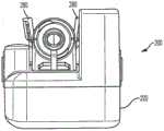
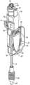
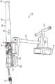
图1是根据本发明的一个实施例的流量传感器系统的指向远侧的立体图。1 is a distally directed perspective view of a flow sensor system according to one embodiment of the present invention.
图2是根据本发明的一个实施例的流量传感器系统的指向近侧的立体图。2 is a proximally directed perspective view of a flow sensor system according to one embodiment of the present invention.
图3A是根据本发明的一个实施例的流量传感器系统的近侧正视图。3A is a proximal elevation view of a flow sensor system according to one embodiment of the present invention.
图3B是根据本发明的一个实施例的流量传感器系统的远侧正视图。3B is a distal elevation view of a flow sensor system according to one embodiment of the present invention.
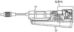
图4A是根据本发明的一个实施例的流量传感器系统的侧视图。4A is a side view of a flow sensor system according to one embodiment of the present invention.
图4B是如由细节A所示的图4A的一部分的放大的细节图。FIG. 4B is an enlarged detail view of a portion of FIG. 4A as shown by Detail A. FIG.
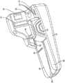
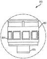
图5A是根据本发明的一个实施例的流量传感器系统的基座的立体图。5A is a perspective view of a base of a flow sensor system according to one embodiment of the present invention.
图5B是图5A的基座的立体图,其示出光学和电气部件。5B is a perspective view of the base of FIG. 5A showing the optical and electrical components.
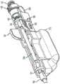
图6是根据本发明的一个实施例的流量传感器系统的流量传感器的立体图。6 is a perspective view of a flow sensor of a flow sensor system according to an embodiment of the present invention.
图7是根据本发明的一个实施例的流量传感器系统的流量传感器的另一个立体图。7 is another perspective view of a flow sensor of a flow sensor system according to an embodiment of the present invention.
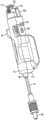
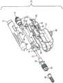
图8是根据本发明的一个实施例的流量传感器系统的流量传感器的分解立体图。FIG. 8 is an exploded perspective view of a flow sensor of a flow sensor system according to an embodiment of the present invention.
图9是根据本发明的一个实施例的流量传感器系统的流量传感器的立体图。9 is a perspective view of a flow sensor of a flow sensor system according to an embodiment of the present invention.
图10A是与根据本发明的一个实施例的流量传感器系统兼容的注射器的侧视图。10A is a side view of a syringe compatible with a flow sensor system according to one embodiment of the present invention.
图10B是如由细节B所示的图10A的一部分的放大的细节图。FIG. 10B is an enlarged detail view of a portion of FIG. 10A as shown by Detail B. FIG.
图10C是用于与根据本发明的一个实施例的流量传感器系统兼容的注射器的提示标签的侧视图。1OC is a side view of a reminder label for a syringe compatible with a flow sensor system according to one embodiment of the present invention.
图11A是用于根据本发明的一个实施例的流量传感器系统的充电器的立体图。11A is a perspective view of a charger for a flow sensor system according to one embodiment of the present invention.
图11B是如由细节C所示的以顺时针角度转动的图11A的一部分的放大的细节图。FIG. 11B is an enlarged detail view of a portion of FIG. 11A rotated at a clockwise angle as shown by detail C. FIG.
图11C是用于根据本发明的一个实施例的流量传感器系统的充电器的俯视图。11C is a top view of a charger for a flow sensor system according to one embodiment of the present invention.
图11D是沿着图11C的线X-X截取的剖视图,根据本发明的一个实施例的流量传感器系统的基座被接纳在充电器的一部分内。11D is a cross-sectional view taken along line X-X of FIG. 11C , with the base of the flow sensor system according to one embodiment of the present invention received within a portion of a charger.
图12是根据本发明的一个实施例的流量传感器和安装件的立体图。12 is a perspective view of a flow sensor and a mounting according to one embodiment of the present invention.
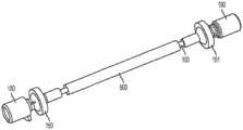
图13是根据本发明的一个实施例的流管子组件的立体图。13 is a perspective view of a flow tube subassembly according to one embodiment of the present invention.
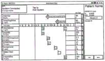
图14A是根据本发明的一个实施例在麻醉(anesthesia)视图中的计算机显示器的示意图。14A is a schematic diagram of a computer display in an anesthesia view according to one embodiment of the present invention.
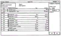
图14B是根据本发明的一个实施例在表格视图中的计算机显示器的示意图。14B is a schematic diagram of a computer display in a table view according to one embodiment of the present invention.
图15是根据本发明的一个实施例的流管子组件的上游部分的立体图。15 is a perspective view of an upstream portion of a flow tube subassembly according to one embodiment of the present invention.
图16是根据本发明的一个实施例的流管子组件的上游部分的立体图。16 is a perspective view of an upstream portion of a flow tube subassembly according to one embodiment of the present invention.
图17是根据本发明的一个实施例的流管子组件的上游部分的立体图。17 is a perspective view of an upstream portion of a flow tube subassembly according to one embodiment of the present invention.
图18A至图18D示出根据本发明的一个实施例的用于将吸收器护套和端部配件施加到流管的过程。18A-18D illustrate a process for applying an absorber jacket and end fittings to a flow tube according to one embodiment of the present invention.
图19A至图19D示出根据本发明的一个实施例的用于将吸收器护套和端部配件施加到流管的过程。19A-19D illustrate a process for applying an absorber jacket and end fittings to a flow tube according to one embodiment of the present invention.
贯穿若干视图,相对应的参考字符表示相对应的部件。这里阐述的范例说明了本公开的例示性实施例,并且这样的范例不应以任何方式限制本公开的范围。Corresponding reference characters indicate corresponding parts throughout the several views.The exemplifications set out herein illustrate exemplary embodiments of the disclosure, and such exemplifications should not limit the scope of the disclosure in any way.
具体实施方式DETAILED DESCRIPTION
提供以下描述以使本领域的技术人员能够制成和使用预料到的所述用于实施本发明的实施例。然而,对于本领域的技术人员来说,各种修改方案、等同方案、变型方案以及可替代方案将容易地保持为显而易见的。任何和所有这样的修改方案、等同方案、变型方案以及可替代方案都应落入本发明的精神和范围内。The following description is provided to enable those skilled in the art to make and use the anticipated embodiments for implementing the present invention. However, various modifications, equivalents, variations and alternatives will easily remain obvious to those skilled in the art. Any and all such modifications, equivalents, variations and alternatives should fall within the spirit and scope of the present invention.
为了以下描述的目的,术语“上”、“下”、“右”、“左”、“竖向”、“水平”、“顶部”、“底部”、“横向”、“纵向”及其派生词应当与本发明相关,如在附图中被取向的那样。然而,应当理解的是,本发明可以采取各种可替代变型,除非有明确地相反规定以外。还应当理解的是,在附图中所示的和在以下说明书中所述的具体装置仅仅是本发明的例示性实施例。因此,与本文公开的实施例有关的具体尺寸和其它物理特性不应当认为是限制性的。For the purpose of the following description, the terms "upper", "lower", "right", "left", "vertical", "horizontal", "top", "bottom", "lateral", "longitudinal" and their derivatives shall relate to the present invention as oriented in the accompanying drawings. However, it should be understood that the present invention may take various alternative variations, unless expressly specified to the contrary. It should also be understood that the specific devices shown in the drawings and described in the following specification are merely illustrative embodiments of the present invention. Therefore, specific dimensions and other physical characteristics related to the embodiments disclosed herein should not be considered limiting.
如本文所使用的,近侧应当指的是位于远离患者或离患者最远的部分或方向(上游),而远侧应当指的是朝向患者或离患者最近的部分或方向(下游)。而且,药剂物质在本文中以说明性的、非限制性的方式用于指为了任何目的可注射到患者的身体内的任何物质。所述及的患者可以是任何生命、人类或动物。所述及的临床医生可以是给予治疗的任何人或事物,例如,护士、医生、机器智能、护理人员,或甚至自我治疗。As used herein, the proximal side shall refer to the portion or direction located away from the patient or farthest from the patient (upstream), while the distal side shall refer to the portion or direction toward the patient or closest to the patient (downstream). Moreover, pharmaceutical substances are used herein in an illustrative, non-restrictive manner to refer to any substance that can be injected into the patient's body for any purpose. The patient mentioned can be any life, human or animal. The clinician mentioned can be any person or thing that gives treatment, for example, a nurse, a doctor, a machine intelligence, a caregiver, or even self-treatment.
图1至图12示出本公开的流量传感器系统200的例示性实施例。参照图1至图12,本公开的流量传感器系统200包括在使用之前配合在一起的两个主要组件:流量传感器210和基座220。在一个实施例中,流量传感器210可以是一次性使用的流量传感器,其可与可重复使用的基座220接合。流量传感器系统200是智能注射端口。流量传感器系统200可附接到用于手动施用的IV注射的注射部位(例如,“Y部位”或管闩)。1 to 12 show an exemplary embodiment of a
本公开的流量传感器系统200能够在推注输送期间减少在床边处的药物错误。本公开的流量传感器系统200还可以提供推注输送的记录和电子地测量推注输送,这允许监测推注输送和将推注输送的自动文档作为患者的健康记录的一部分。当即将出现与患者的医疗记录不一致的推注输送时,本公开的流量传感器系统200还可以提供警报。The
参照图1至图5B,在一个实施例中,基座220是容纳电池、扫描仪(光学式、机械式、感应式、电容式、接近式或RFID式)、电子器件和无线发射器的非无菌的、可重复使用的装置。在某些实施例中,基座220是电池供电的并且是可再充电的。在某些实施例中,每个基座220都具有压印在基座220的表面上或嵌入其中的唯一的序列号,所述序列号可以在使用之前被传输到数据系统。数据系统可以是本地计算机或平板“计算机”、移动电话、其它医疗装置或医院数据系统。With reference to Fig. 1 to Fig. 5B, in one embodiment,
在一个实施例中,基座220可以被可拆卸地连接到流量传感器210。参照图5A和图6至图9,描述基座构件220以及流量传感器210与基座构件220的机械连接。基座构件220包括至少一个可偏转的翼片280,其限定开口,所述开口用于在其中接纳流量传感器210的至少一部分并且用于在使用之前将流量传感器210固定在基座220的一部分内。在一个实施例中,一对翼片280将流量传感器210固定在基座220内。可以在外部型面上设置有任选的夹持肋部395以用于使得使用者能够抓握基座部分220。In one embodiment, the base 220 can be removably connected to the
翼片280的内部型面可以设置有捕捉部389,用于与设置在流量传感器210上的凸片189(如在图6中所示)相对应地接合,以将流量传感器210约束在基座220内,如将在本文中进一步述及的那样。翼片280可以是挠性的,以致于达到使翼片可以向外偏转而允许供流量传感器210在其上通过的程度。翼片280的内部可以设置有销凸轮388,允许流量传感器210的销188如图7中所示沿其前行,使得流量传感器210在组装到基座220上期间向近侧地运动以精确地对准基座构件220和流量传感器210的各种光学和电气部件,如将在本文中进一步述及的那样。The inner profile of the
参照图5B和图6至图9,描述基座构件220以及流量传感器210与基座构件220的电连接。基座220包括激活/接合按钮350,其允许用于指示流量传感器210已经与基座220接合。在一个实施例中,激活/接合按钮350向基座220内的微处理器发信号,以通知注射器已经适当地与传感器210及其注射端口130接合的情况。5B and 6-9, the
基座220还包括多个触点386(图5B),用于电接合多个触针385(图7)的相对应的电活性部分。轮廓突起488包围舌部286的至少一部分。如图7中所示,传感器200的底部表面包括触针密封件384,其包围多个触针385以防止污染,从而使电中断最小化。在某些实施例中,多个触针385包括四触针连接器,所述四触针连接器具有电连接到每个压电元件150、151的两个触针,如将进一步讨论的。在另一些实施例中,多个触针385包括六触针连接器,所述六触针连接器具有电连接到每个压电元件150、151的两个触针以及电连接到流量传感器210中的电池(未示出)的两个触针。The base 220 also includes a plurality of contacts 386 (FIG. 5B) for electrically engaging corresponding electrically active portions of a plurality of contact pins 385 (FIG. 7). A
基座构件220还包括由肩部486包围的舌部286,所述舌部286具有多个触点386,用于电接合传感器200和充电器900(图11A)的相对应的电活性部分,如将在本文中述及的那样。The
参照图1至图4B、图6至图9以及图13,在一个实施例中,流量传感器210是预先消毒的一次性的,其具有注射端口130和远侧管材连接,例如,鲁尔尖端109。1-4B , 6-9 , and 13 , in one embodiment, the
流量传感器210可以包括流管子组件10,所述流管子组件10由具有出口端部101和入口端部102的流管100组成。出口端部101可以设置成与出口管材110流体连通,所述出口管材110具有出口连接件105,所述出口连接件105包括鲁尔尖端109,所述鲁尔尖端109可以任选地由鲁尔帽108遮盖。在一个优选实施例中,出口连接件105是具有鲁尔尖端109的塑料连接器,然而,在本发明的实施例的方面内将设想到任何合适的将药剂注射到患者体内的方法。例如,会期望的是,用针头替换出口连接件105和管材110以用于直接注射/输注到患者体内。此外,会期望的是将基座220集成到用于输送胰岛素的药物笔或输注装置中。The
入口端部102可以联接到药物笔的贮器或输注贮器。流管100的入口端部102可以设置成与注射端口130流体连通,并且可以任选地包括连接件,例如,可与待注射的流体的源接合的螺纹鲁尔锁131。可刺穿的隔膜139可以与注射端口130一起设置,以用于在使用之前维持无菌性。The
在一个优选实施例中,注射端口130是具有分裂隔膜139的塑料容器,然而,在本发明的实施例内将设想到任何合适的通过流量传感器入口180将药剂注射到患者体内的方法。例如,会期望的是,替换注射端口130以用于直接连接到药剂输送装置。另外,会期望的是,集成流量传感器入口180以接受直接流体连接到药物输送装置。In a preferred embodiment, the
在一个实施例中,流管100由医疗级不锈钢构成,并且具有大约50mm的长度、1.0mm的内直径以及1.6mm的外直径。In one embodiment,
流量传感器210还包括第一压电元件或上游换能器150和第二压电元件或下游换能器151。第一压电元件150可以设置有入口配件180,如图8中所示,用于与注射端口130联接。类似地,第二压电元件151可以设置有出口配件190,用于与出口管材110联接。The
流量传感器210可以在无菌包装中被供给以用于单个患者使用。在一个实施例中,标签被印刷在单独的无菌包装上。在一个实施例中,每个流量传感器210都具有压印在其表面的一部分上的唯一的序列号。在某些实施例中,在流量传感器210中存在有保持唯一的标识符的电子器件。这些标识符在使用和数据收集期间被自动地或手动地传输到数据系统。在一个实施例中,在流量传感器210的入口端部102处,注射端口130是常见的无针式鲁尔洛克(Luer-Lok)型。典型地,入口端口或注射端口130在根据医院政策而提供注射之前被清洁。另外,在使用之前,期望的是用IV流体(例如,生理盐水注射器)冲洗流量传感器210。流量传感器210上的注射端口130典型地支持多达100次注射。在一个实施例中,流量传感器210在出口端部101处的一英寸IV管材尾端上具有阳鲁尔洛克连接件,例如,具有鲁尔尖端109的出口连接件105。该阳鲁尔洛克连接件可以在Y部位或IV歧管处附接到IV管线。每个流量传感器210都具有唯一的序列号,然而,会期望的是仅在流量传感器210的外部的一部分上显示序列号的一部分。例如,序列号的最后4位数字可以被压印在其条形码旁的表面上。该人类可读数字被用于在计算机的无线通信范围内以可视方式识别出流量传感器210。在某些实施例中,流量传感器210对于1.0mL至55mL的推注体积而言以±5%的准确度测量并且对于0.4mL至1.0mL的推注体积而言以±20%的准确度测量,并且具有小于0.3mL的死腔体积。The
参照图11A至图11D,在一个实施例中,任选的单独的充电器900与流量传感器系统200兼容,并且如果需要的话对可重复使用的基座220中的电池再充电,用于使基座220重复使用。参照图11A至图11D,在一个实施例中,充电器900包括充电器基座905,所述充电器基座905具有用于接纳基座220的开口925,该开口925具有充电插脚950,其与可重复使用的基座220中的相对应的触点386接合。充电器900可以包括倾斜的底板930以用于允许消毒液从其排放。该装置还可以包括升高的脚部999以帮助排放。Referring to Figures 11A to 11D, in one embodiment, an optional
可重复使用的基座典型地以非无菌状态被供给,并且在使用之前需要消毒和充电。优选的是在首次使用之前对每个基座220消毒。典型的市售医院消毒剂包括醇基季铵,例如,Metrex Research Cavi Wipes。在某些实施例中,基座220可以使用多达500次。优选地,在基座220内使用可再充电的锂离子电池,并且不可从基座220移除该可再充电的锂离子电池。设想到,充满电的基座220将满足整个患者病例过程。在某些实施例中,每个基座220都通过在装置的底部上贴标签来标识出。任选地,基座220被设置在单独的盒中,并且每个盒都处于病例包装中。充电器900还可以包括电源指示器995。在一个实施例中,当基座220连接到充电器900时,多达四个绿色灯条将在顶部上照亮。实心绿色灯条的数目指示充电的水平。基座220上的绿色闪烁的灯将指示它正在充电。在某些实施例中,当基座220连接到充电器900时,借助于使用红灯(所述红灯指示基座220已经超过其使用寿命)而采用可用寿命指示器。任选地,在计算机上,当患者在设定期间将其使用寿命业已完结的流量传感器系统200无线连接到平板电脑时,将显示错误消息。然后,将期望的是,将基座220用另一个基座替换,并且重复与计算机的无线连接。任选地,流量传感器系统200被设置在安装件中,所述安装件是配合标准克拉克插座以将流量传感器系统200保持在患者床边处的适当位置中的器具。另外,会期望的是,通过使用用于对基座220清洁和消毒的程序来对充电器900清洁和消毒。Reusable bases are typically supplied in a non-sterile state and require disinfection and charging before use. It is preferred to disinfect each base 220 before first use. Typical commercially available hospital disinfectants include alcohol-based quaternary ammonium, for example, Metrex Research Cavi Wipes. In some embodiments, the base 220 can be used up to 500 times. Preferably, a rechargeable lithium-ion battery is used in the
在一个实施例中,流量传感器系统200使用任何鲁尔锁(Luer-lock)式注射器支持注射。例如,参照图10A至图10C,流量传感器系统200与被标注的注射器800兼容。在一个实施例中,注射器800包括刻度标志805、远侧尖端810、鲁尔尖端815、近侧端部820、凸缘825、具有人类可读标记852和机器可读标记854的提示标签850、具有人类可读标记862的筒管标签860,和柱塞890。In one embodiment, the
流量传感器系统200的基座220包括布置在第一窗口360(图2)内或后面的光学器件和数字照相机,所述光学器件和数字照相机能够读取在编码注射器的标签850上提供的机器可读标记854。当流量传感器210与基座220组装在一起时,第一窗口360可以精确地与存在于流量传感器210上的鲁尔锁螺纹131对准,从而在注射周期和/或药物确定周期期间对准存在于注射器800上的标签850上的机器可读标记854。基座220还可以包括具有光源的第二窗口370(图5A和图5B),所述光源用于向布置在窗口360内或后面的照相机提供充分的照明。The
另外,流量传感器系统200被设计为与编码注射器一起工作,所述编码注射器在注射器的鲁尔轴环上具有特定条形码标识符,这被称为“编码”。优选地,编码注射器包括在具有特定条形码的预填充注射器中的市面上可购得的药物,所述特定条形码存储关于容纳在注射器内的药物的信息。编码注射器是即用型的、被动式的和一次性的。流量传感器系统200还适应于不具有编码的注射器。编码注射器存储容纳在注射器内的药物的名称和浓度。额外的特性,例如,药物源、容器大小、制药商源、药品类别颜色等,也可以包含在内。当编码注射器附接到流量传感器210的注射端口130时,该条形码信息被基座220中的扫描仪读取,由流量传感器系统200无线发送到数据系统。优选地,在填充处理期间,2-D条形码将被添加到注射器。In addition, the
在一个实施例中,流量传感器系统200包含有用于捕获和传输在注射器的鲁尔轴环上的2-D条形码的图像的装置,并且将该图像无线传输到“计算机”。典型地,该计算机是与多个流量传感器系统200通信的平板计算机。2-D条形码包含有数据,所述数据典型地包括在注射器中的药物的名称和浓度以及其它数据。计算机对该图像解码,并且显示和告知所附的药物。条形码可以包含有药物名称和浓度。随着药物被注射,与基座220协同的流量传感器210超声地测量注射的药物的体积和药物的施用时间。该信息可以被存储在流量传感器系统200中,以便稍后传输到计算机。计算机使用该信息为临床医生提供药物名称、浓度、体积、剂量和注射时间的自动记录。药物管理信息被加盖时间戳并且被显示以用于临床参考。并非所有由医护专业人员使用的注射器都含有2-D条形码。如果没有2-D条形码的注射器被插入流量传感器系统中,则注射端口130、流量传感器系统200将提示使用者将药物名称和浓度手动地输入到计算机中。手动输入到流量传感器系统200中的信息被包含在患者用药记录中。In one embodiment, the
在一个实施例中,计算机可以使用无线电使用在2.4GHz下的RF信号与流量传感器系统200无线通信,以形成本地医疗装置网络。可以在同一区域使用多个流量传感器系统200和计算机,例如,术前护理区域或麻醉术后恢复室(PACU)。在流量传感器系统200和计算机之间传送警报消息以向临床医生建议流量传感器系统200的各种操作特性。这些警报中的某些告知临床医师潜在的危险情况以允许使用者采取行动,以防止对患者造成伤害或丢失医疗数据。优选地,当流量传感器系统200与计算机之间的通信失联时,将显示无线通信消息失联。优选地,来自流量传感器系统200的所有药物施用数据被传送到特定患者的医疗记录。在通信失联的情况下,药物施用数据将在本地被存储在流量传感器系统200处,并且当通信恢复时被传送到计算机。In one embodiment, the computer can use a radio to communicate wirelessly with the
计算机可以在各种模式中操作。典型地,计算机具有用于操作的专用流量传感器系统200软件、触摸屏和无线通信(无线电)。计算机被典型地安装在麻醉师或护理工作包封附近,并且它可以被移除以供手持使用。当计算机在具有纸张麻醉记录的医院中使用时,计算机支持协助归档流程图部分的功能,并且可以帮助临床医生做出正确的决定。在该配置中,计算机通过追踪和显示通过流量传感器系统200给出的注射来补充纸张记录保存活动。计算机还使临床医生能够手动归档其它相关IV药物注射和输注信息。The computer can operate in various modes. Typically, the computer has a dedicated
在一个实施例中,软件屏幕遵循由以下三个步骤组成的三步骤的方法:(1)将流量传感器系统200连接到计算机;(2)设立患者的流量传感器系统200以供使用;以及(3)以多个视图查看药物施用。In one embodiment, the software screens follow a three-step method consisting of: (1) connecting the
在某些实施例中,计算机上的视图显示在麻醉视图中的基于麻醉的信息,如在图14A中所示。优选地,该视图提供关于患者的信息并且显示用于当前注射的药物名称/浓度和剂量以及自从当前病例被打开以来已经输送给患者的药物的历史列表。该视图还包括给予患者的输注清单,如果临床医师在计算机上记录所述输注清单的话。在该视图中,多达三个注射条横过屏幕的顶部显示,一个注射条与每个无线连接的流量传感器系统200相对应。每个注射条都是通过单独的流量传感器系统200施用药物的实时表示。当编码注射器被附接到单个流量传感器系统200时,注射条显示药物名称和浓度。当非编码注射器被附接时,注射条将提示临床医生识别正在输送的药物和浓度。随着药物正被输送,推送的体积(以mL为单位)和相对应的剂量实时显示在计算机显示器上的注射条中。In certain embodiments, the view on the computer displays information based on anesthesia in the anesthesia view, as shown in Figure 14A. Preferably, the view provides information about the patient and displays the name/concentration and dosage of the drug currently injected and the history list of the drug delivered to the patient since the current case was opened. The view also includes a list of infusions given to the patient, if the clinician records the infusion list on the computer. In this view, up to three injection bars are displayed across the top of the screen, and one injection bar corresponds to each wirelessly connected
本公开的流量传感器系统200还可以提供任选的药物史。例如,麻醉视图可以包括由以流程图格式布置的手术护理区域所组织的、输送给患者的药物的历史列表(在护理区域之间的过渡时间中给出的药物,将发布到下一个护理区域)。优选地,该视图优选地在列表的底部处包括自从流量传感器系统200用较新近的药物施用激活以来给予患者的所有药物。当列表超出计算机的屏幕上的可见空间时,将启用滚动条。优选地,当添加新的药物时,药物列表自动地滚动,所以使新的药物名称可见。在视图中,优选地,与美国国际检测与材料协会(ASTM)标准相对应的并且由美国麻醉医师协会认可的彩色平面图像显示到药物名称的左侧。任选地,临床医生也可以指定输送掺合物(混合的药物)或稀释的或重构的药物。任选地,计算机显示一病例标题,其中列出患者姓名、出生日期、年龄、病历编号和患者识别号码。任选地,计算机将指示患者具有“未知的过敏症”。优选地,如果患者具有过敏症,则文本通过按钮更换,更优选地,并且按钮在按钮上具有指示过敏症状的数量的数字。The
如图14B中所示,本公开的流量传感器系统200还可以提供任选的表格视图。例如,表格视图是用于使临床医生与流量传感器系统200相互作用的可替代视图。与上述的麻醉视图类似,该视图提供关于患者的信息并且显示用于当前注射的药物名称/浓度和剂量以及已经输送给患者的药物的历史列表。该视图还可以包括给予患者的输注清单,如果由临床医师记录所述输注清单的话。表格视图具有麻醉视图的特征中的许多;然而,表格视图是以表格格式布置。优选地,该视图中的列标题包括施用时间、药物浓度、剂量和单位总量。优选地,药物按时间倒序显示,在列表的顶部处为最新的药物。As shown in FIG. 14B , the
在一个实施例中,计算机提供两种类型的消息:(1)“临床”和(2)“系统”。临床消息是警报和提醒,其直接涉及患者护理服务的方面(例如,禁忌症或提醒,其可以是再给予抗生素的时间)。系统消息提供关于相关的系统操作参数的状态。In one embodiment, the computer provides two types of messages: (1) "clinical" and (2) "system." Clinical messages are alarms and reminders that directly relate to aspects of patient care services (e.g., contraindications or reminders, which may be time to re-administer antibiotics). System messages provide status regarding relevant system operating parameters.
消息提供用于确认或解决的指令和按钮。消息显示在计算机上,直到它们被确认或不再具有临床相关性为止。消息可以在病例期间随时被回答。在暂停或关闭病例之前,临床医生被提示响应/回答在病例期间产生的未解决的药物消息。当临床医生附接编码注射器或为具有已知的过敏症的患者的未编码注射器选择药物时,过敏警报照亮流量传感器系统200并且在计算机上显示。任选地,该消息可以被不予考虑。The messages provide instructions and buttons for confirmation or resolution. Messages are displayed on the computer until they are confirmed or no longer clinically relevant. Messages can be answered at any time during the case. Before pausing or closing the case, the clinician is prompted to respond/answer unresolved medication messages generated during the case. When the clinician attaches a coded syringe or selects a medication for an uncoded syringe for a patient with a known allergy, the allergy alarm illuminates the
当给予抗生素时,优选地,计算机追踪自从上次施用抗生素以来所经过的时间,并且如果配置的再给药时间隔已经过去,则显示并且告知抗生素再给药消息。再给药时间间隔对于每种抗生素是单独的,并且被配置在计算机或网关的药品库中(下面进一步描述)。在一个实施例中,流量传感器系统200不阻止或阻隔药物的注射。在另一些实施例中,流量传感器系统200能够阻隔药物的注射。When administering antibiotics, preferably, the computer tracks the time elapsed since the last administration of the antibiotics, and displays and communicates an antibiotic re-administration message if the configured re-administration interval has passed. The re-administration interval is individual for each antibiotic and is configured in the drug library of the computer or gateway (described further below). In one embodiment, the
在一个实施例中,当通过流量传感器系统200注射的体积未被测量到时,计算机发布消息。当所测量的体积在流量传感器系统200的感测范围之外时,会发生这种情况。In one embodiment, the computer issues a message when the volume injected by the
任选地,计算机与软件应用双向地无线通信,所述软件应用充当与所有计算机(并且从而在多个流量传感器系统200上有多个计算机)连接的中心枢纽,“网关”。优选地,网关也连接到医院的其它联网信息系统。网关允许所有的计算机相互之间借助医院的联网信息系统共享患者病例信息,例如,药物名称、剂量以及彼此输送的时间。网关还允许计算机从其它联网的医院信息系统接收患者信息,例如,患者药物过敏症和患者药物序列。Optionally, the computer communicates bidirectionally wirelessly with a software application that acts as a central hub, a "gateway," to which all computers (and thus multiple computers on multiple flow sensor systems 200) are connected. Preferably, the gateway is also connected to other networked information systems of the hospital. The gateway allows all computers to share patient case information with each other via the hospital's networked information systems, such as medication names, dosages, and times of delivery with each other. The gateway also allows the computers to receive patient information from other networked hospital information systems, such as patient medication allergies and patient medication sequences.
对本公开的流量传感器系统200的利用包含有将流量传感器210连接到患者的导管或注射端口(Y部位)的步骤。优选地,流量传感器210和管线被冲洗。流量传感器210使用唯一的序列号键入给各个患者,并且基座220通过在流量传感器210的入口端部102处的端口记录药物施用。Utilization of the
当注射器800连接到注射端口130时,流量传感器系统200通过对注射器800的鲁尔洛克套环上的条形码光学成像和解码来识别出用于编码注射器的药物和浓度。该信息被无线传输到计算机。优选地,计算机显示并且可听地告知所附的药物。计算机也可以基于患者的病历而执行过敏安全检查。When a
在一个实施例中,随着药物被注射,流量传感器系统200超声地测量给药的体积。流量传感器系统200将体积测量信息无线发送到计算机。计算机使用该信息为临床医生提供药物施用记录,所述药物施用记录被加盖时间戳并且在外科手术期间显示以用于供临床参考。手动输入的输注和其它与非编码药物注射有关的信息可以被包含在计算机和网关中的患者用药记录中。计算机与医院网络上的网关无线通信,并且计算机可以当配置时将药物施用发送到医院信息系统,用于报告和电子记录保存目的。优选地,计算机使用基于标准的IEEE802.11a/b/g/n企业WLAN网络来与现有的医院网络无线通信。网关软件和伴随的数据库将成为医院的企业信息系统的一部分。许多计算机可以连接到医疗保健企业无线网络以及预期的网关软件和数据库。优选地,网关和伴随的数据库提供用于供使用者选择的患者列表以及用于注射或输注的药物和流体的处方库。在一个实施例中,实际的药物和流体施用数据被发送到网关和伴随的数据库以用于记录保存。一旦被记录在网关和伴随的数据库上,则当患者被转移并且流量传感器系统200无线连接到计算机时,这些数据优选地可用于其它护理区域。优选地,在通信失联的情况下,药物施用数据将不被发送到网关,并且因此不可用在下一个护理区域中。In one embodiment, as the drug is injected, the
参照图1至图12,现在将描述本公开的流量传感器系统200的使用。首先,将讨论制备流量传感器系统200以用于注射。1-12, the use of the
在一个实施例中,流量传感器系统200被制备,被附接到IV管线,并且被组装以供使用。优选地,在流量传感器210无菌袋上设有预印刷的指令。首先,使用者获得在其无菌包装中的流量传感器210,并且获得充满电的并且消过毒的可重复使用的基座220。在一个实施例中,在典型的条件下,充满电的基座220具有足够的能量,能够使用至少24小时。任选地,基座220经由显示器提供充电水平的可视指示。In one embodiment, the
接下来,流量传感器210在附接到Y部位之前用无菌IV流体冲洗。在一个实施例中,流量传感器210用超过8mL的无菌IV流体冲洗。在冲洗之后,使用者可以目视检查IV管线,以检查有无泄漏、空气或堵塞。Next, the
接下来,使用者首先通过将流量传感器210(管材侧)和基座220前段连结并且继而通过将两者咬合在一起而将流量传感器210附接到基座220。优选地,听到可听见的噼啪声来指示流量传感器210与基座220之间的安全连接。在一个实施例中,将流量传感器210连接到基座220自动地对流量传感器系统200提供能量。在一个实施例中,流量传感器210与基座220的连接通过基座220上的闪烁的灯来验证。在另一些实施例中,可以使用其它指示器。图5A中所示的基座220的捕捉部389与图6中所示的流量传感器210的凸片189接合,以在开始注射之前用基座220约束流量传感器210。在一个实施例中,翼片或多个翼片280的偏转使凸片189相对于捕捉部389运动以开始与其接合或脱离。当流量传感器210组装到基座220时,设置在基座220上的悬臂650(例如,如下文将讨论的下壳体212)与设置在基座220上的按钮350对准。翼片280的内部还可以设置有销凸轮388,其允许如图6中所示的流量传感器210的销188沿其前行,使得流量传感器210在组装到基座220上期间向近侧地运动。在接合期间,图5A中所示的舌状物286被接合在图7中所示的开口285内。继续参照图5A和图7,如图7中所示,在流量传感器210上的具有肋部487的拱顶485具有与借助基座220的肩部486得到的型面相对应的外部型面,如图5A中所示,以便当流量传感器210组装到基座220时接合来用于使第一窗口360与鲁尔锁螺纹131精确地对准。Next, the user attaches the
在某些实施例中,在适当的情况下,流量传感器系统200在制备中被固定到表面以用于提供注射。例如,在某些实施例中,参照图12,使用安装件1100将流量传感器系统200固定到表面。在该步骤中,重要的是避免流量传感器系统200与IV管线之间的线路中的扭结。In some embodiments, where appropriate, the
流量传感器系统200现在准备好输送IV药物。优选地,通过流量传感器系统200给出的任何药物将被记录在电子基座220存储器中。在一个实施例中,在流量传感器系统200出现故障(排除IV流体路径)的情况下,流量传感器系统200将仍允许通过端口的标准药物或流体输送。The
接下来,将讨论使用流量传感器系统200提供注射。首先,根据正常的医院程序通过擦拭接口(hub)来清洁注射端口130。接下来,通过完全地转动注射器800,直到注射器800停止为止,即,在注射器800与流量传感器210的注射端口130之间形成安全连接,可以将注射器800附接到流量传感器210的注射端口130。在理想情况下,护理人员在将注射器800附接到注射端口130之前双重检查注射器800上的每个药物名称和浓度,以确保给出正确的药物。在注射周期和/或药剂确定周期期间,当注射器尖端810接触如图4B中所示的注射器突起652时,悬臂650从注射器800的纵向轴线径向地偏转。垫突起651按压基座220上的按钮350,并且按钮350发信号通知微处理器起作用。Next, providing an injection using the
接下来,由计算机显示和告知的药物和浓度被验证为预期的药物和浓度。在一个实施例中,如果检测到药物过敏,则基座220将通过警报例如通过闪光的红色、绿色和黄色的灯来警告护理人员检测到过敏。任选地,计算机计算潜在的过敏反应,并且当以下这些条件中的任一个为真时提供警报:(1)编码注射器被插入流量传感器210中,并且药物与患者的过敏概况匹配;或(2)非编码注射器被插入流量传感器210中,并且您从选择药物屏幕中选择了与患者的过敏概况匹配的药物。如果这些条件之一为真,则计算机配置上的过敏警告标志将打开。Next, the medication and concentration displayed and communicated by the computer are verified as the expected medication and concentration. In one embodiment, if a medication allergy is detected, the
在一个实施例中,在流量传感器210中既没有止回阀,也不需要安全地且高效地使用流量传感器210。典型地,流量传感器系统200每次注射测量0.4mL至55mL。如果注射流率较慢或输送较小的体积(<0.4mL),则优选地警报将在计算机上显示。任选地,警报被配置为检测来自大体积(例如50mL)的注射器的快速输送。在这种情况下,提供警报来检查剂量。In one embodiment, there is neither a check valve in the
在一个实施例中,指示器375,例如一系列四个LED指示器,依次打开,以向使用者指示流体正在流过流量传感器210。当基座220安装在充电器900中时,指示器375可以指示基座220的电池充电水平。In one embodiment, the
在一个实施例中,优选的是借助编码的生理盐水冲洗注射器遵循通过流量传感器系统200的全部药物注射,以便尤其当相继地输送两种不相容的药物时,确保药物的全部剂量到达患者。任选地,流量传感器系统200记录这样的盐水冲洗活动。In one embodiment, it is preferred to follow all medication injections through the
在一个实施例中,无论流量传感器系统200是否无线连接到计算机,都对注射进行记录。基座220将注射信息存储在其存储器中,并且在无线连接到计算机时,发送该信息。In one embodiment, the injection is recorded whether or not the
在一个实施例中,计算机可以适应一次连接到一个患者的多个流量传感器系统200。可以在患者治疗期间的任何时间添加额外的流量传感器系统200。当流量传感器系统200连接到计算机并且没有注射器附接到流量传感器210时,主动注射条读取“传感器已连接,无注射器”。在计算机显示器上,在注射条的右上角中的电池状态图标指示与流量传感器210连接的基座220的电池充电水平。对于每次注射而言,护理人员都可以在计算机上输入评论。In one embodiment, the computer can accommodate multiple
本公开提供一种用于感测流体药剂的流动的流量传感器子组件。流量传感器子组件包括第一弹簧触点和第二弹簧触点。在一个实施例中,弹簧触点被固定到基座,所述基座具有电路,所述电路用于将来自和去向弹簧触点的电信号传导到微处理器。第一弹簧触点与第一压电元件电通信,并且第二弹簧触点与第二压电元件电通信。第一弹簧触点具有抵靠第一压电元件的第一接触力,第二弹簧触点具有抵靠第二压电元件的第二接触力,并且第一接触力等于第二接触力。本发明还提供一种电路板,所述电路板用于经接口连接到(interfacing to)具有多个压电元件的流量传感器以用于传输指示流体药剂的流动的流量信号。The present disclosure provides a flow sensor subassembly for sensing the flow of a fluid medicament. The flow sensor subassembly includes a first spring contact and a second spring contact. In one embodiment, the spring contact is fixed to a base, and the base has a circuit for conducting electrical signals from and to the spring contact to a microprocessor. The first spring contact is in electrical communication with a first piezoelectric element, and the second spring contact is in electrical communication with a second piezoelectric element. The first spring contact has a first contact force against the first piezoelectric element, the second spring contact has a second contact force against the second piezoelectric element, and the first contact force is equal to the second contact force. The present invention also provides a circuit board, which is used to be connected to (interfacing to) a flow sensor having multiple piezoelectric elements via an interface for transmitting a flow signal indicating the flow of a fluid medicament.
本公开的弹簧触点向压电元件提供电接触。例如,本公开的弹簧触点向压电晶体的镀银表面提供电接触。此外,这种接触提供这样的弹簧力,即,所述弹簧力被选择用以适应组装公差、温度变化、电气要求、用于银的较长寿命的材料选择以及用于单面印刷电路板组件(PCBA)附件的组装特征。本公开的流量传感器子组件提供以用于使在传感器中使用的四个触点在单个换能器中在两个压电元件(例如,晶体)中的每个的两个表面上具有相同的力。The spring contacts of the present disclosure provide electrical contact to the piezoelectric element. For example, the spring contacts of the present disclosure provide electrical contact to the silver-plated surface of the piezoelectric crystal. In addition, such contact provides a spring force that is selected to accommodate assembly tolerances, temperature variations, electrical requirements, material selection for the longer life of silver, and assembly features for single-sided printed circuit board assembly (PCBA) accessories. The flow sensor subassembly of the present disclosure provides for the four contacts used in the sensor to have the same force on both surfaces of each of the two piezoelectric elements (e.g., crystals) in a single transducer.
本公开的电路板提供单面PCBA。本公开的单面PCBA提供比传统的双面PCBA设计更低的成本设计。本公开的电路板还提供当换能器插入PCBA时维持晶体触点的机械负载的措施。The circuit board of the present disclosure provides a single-sided PCBA. The single-sided PCBA of the present disclosure provides a lower cost design than the traditional double-sided PCBA design. The circuit board of the present disclosure also provides a measure to maintain the mechanical load of the crystal contacts when the transducer is inserted into the PCBA.
先前已经通过将线材焊接到银涂层来实现与超声波晶体的电接触。本公开的弹簧触点通过使用弹簧触点连接到晶体而提供成本降低的方法。尤其,本公开的单面印刷电路板(PCB)提供以用于更低成本的设计和通孔接触设计。本公开的设计包括乘以弹簧常数的力施加、触点之间的分离尺寸、弹簧的材料类型、必需的力的范围、以及由弹簧触点所施加的力的公差控制,它们全部对于消除焊接是重要的。如果焊接过热,则焊接经常从晶体表面除去银。焊接的另一个问题是在后面留下太多的焊料,这也会促使超声波物理特性的加载。对于两个晶体的一致的电气和物理接触(可重复性)是与传感器到传感器的校准一样重要的。力不能太高(可能发展浆体)或太低(可变阻抗)。Electrical contact with ultrasonic crystals has previously been achieved by soldering wires to a silver coating. The spring contacts of the present disclosure provide a method of reducing costs by connecting to the crystal using spring contacts. In particular, the single-sided printed circuit board (PCB) of the present disclosure provides for a lower cost design and a through-hole contact design. The design of the present disclosure includes force application multiplied by the spring constant, the separation size between the contacts, the material type of the spring, the range of forces required, and the tolerance control of the force applied by the spring contacts, all of which are important for eliminating soldering. If the soldering is overheated, the soldering often removes silver from the surface of the crystal. Another problem with soldering is that too much solder is left behind, which can also contribute to the loading of ultrasonic physical properties. Consistent electrical and physical contact (repeatability) for the two crystals is as important as sensor-to-sensor calibration. The force cannot be too high (may develop slurry) or too low (variable impedance).
本公开的流量传感器子组件提供较高体积的一次性设计,该设计对于其成本、可靠性和可重复性具有益处。本公开的流量传感器子组件允许用于将来的自动化特征。本公开的流量传感器子组件提供以用于在各种条件下设计的最大容差。本公开的流量传感器子组件能够配合在流量传感器210的壳体中。The flow sensor subassembly of the present disclosure provides a higher volume disposable design, which has benefits for its cost, reliability and repeatability. The flow sensor subassembly of the present disclosure allows for future automation features. The flow sensor subassembly of the present disclosure provides for maximum tolerance designed for under various conditions. The flow sensor subassembly of the present disclosure can be fitted in the housing of the
参照图8、图13和图15至图17,流管子组件10包括流管100、出口连接件105、出口管材110、注射端口130、第一压电元件或上游换能器150、第二压电元件或下游换能器151、入口配件180、出口配件190、配件185和/或吸收器护套400或500。流管子组件10可以是被容纳在流量传感器壳体211、212内的本公开的流量传感器210子组件的一部分。流量传感器壳体212的一部分联接到流量传感器基座220,所述流量传感器基座220包含有微处理器和电路,所述电路包括连接销,其用于将来自流量传感器210子组件的电信号提供到流量传感器基座220内的微处理器。包括流管子组件10的流量传感器210子组件可以在包括流管子组件10的流量传感器210子组件被用于感测至少一种流体药剂的流动之后布置。流量传感器基座220可以与包括多个不同的流管子组件10的多个不同的流量传感器210子组件一起使用。在一种配置中,用于流量传感器210的子组件10可以用作流量传感器210并且被直接插入基座220中,而不是作为流量传感器210的壳体211、212的部件。8, 13, and 15-17, the
如图13中所示,供药剂流过的流管100具有流管入口102和流管出口101。流管入口102可以联接到药物笔的贮器或输注贮器。如本文所述,在某些实施例中,流管100的流管入口102可以设置为与注射端口130流体连通。As shown in FIG. 13 , the
流管100包括内部流管100和端部配件,例如,在入口端部102处的入口配件180和在出口端部101处的出口配件190,用于将流管100固定到在流管100的端面处的相应的端部配件180、190。参照图18A至图18D和图19A至图19D,可以使用配件粘合剂186以将流管100配件管界面区157结合到端部配件180、190,使得来自第一压电元件150和第二压电元件151的能量更为优化地横过配件管传输区158传输。配件粘合剂186阻抑横过配件管界面区157的能量传递,而同时使在配件管传输区158处的损失最小化。优选地,配件粘合剂186阻抑通过在第一压电元件150和第二压电元件151与端部配件180、190之间传递声能而在端部配件180、190中产生的异相和/或劣质(rogue)振动。优选地,配件粘合剂186是低粘度的医疗级粘合剂,其能够经由毛细管作用流入填充间隙中,例如,如图18B和图19B中所示。在配件管传输区158中,会期望的是,在外直径与流管100和端部配件180、190之间有空气间隙,因为这可以减少或防止对于待由微处理器检测的主信号形成干扰的异相和/或劣质能量传输。然而,不管配件管传输区158的配置如何,在某些实施例中,会期望的是流管100与流管100的侧壁有最小接触并且在流管100的端面处的端部配件180、190处有最大接触。在组装期间,这是通过在朝向端部配件180、190的方向上在流管100上施加纵向偏压力来实现的,这是因为配件粘合剂186永久地结合流管100和端部配件180、190。优选地,配件粘合剂186在灭菌之后维持其期望的性质。吸收器的材料可以是任何聚合物或弹性体中的一种,例如,聚氯乙烯、硅橡胶和类似物。在一个实施例中,吸收器的材料可以本质上是柔性的并且具有比流管的硬度(durometer)低的硬度。通过提供具有与流管的硬度不同的且比其低的硬度的吸收器,振动被维持在吸收器内而不是传入流管中。在吸收器和流管的界面处是边界,并且在边界处的能量的行为本质上具有两个可用的因素:反射和透射/折射。反射波和透射波将服从斯涅尔定律。The
第一压电元件150布置在流管100的上游位置处,并且第二压电元件151布置在流管100的下游位置处。第一压电元件150和第二压电元件151被配置为传输指示流管100中的流体药剂的流动的流量信号。在一个实施例中,第一压电元件150和第二压电元件151具有环形的形状并且在每个相应的安装点处环绕流管100。在一个实施例中,第一压电元件150和第二压电元件151被安装成以预设定距离彼此分开。在一个实施例中,弹簧触点750中的每个都被固定到基座,例如,电路板700。电路板700包括用于将来自和去向弹簧触点750的电信号传导到微处理器。第一弹簧触点750与第一压电元件150电通信,并且第二弹簧触点750与第二压电元件151电通信。第一弹簧触点750具有抵靠第一压电元件150的第一接触力,并且第二弹簧触点750具有与第二压电元件151接触的第二接触力。在一个实施例中,第一接触力等于第二接触力。优选地,上游换能器150和下游换能器151是可互换的,然而,设想到,上游换能器150和下游换能器151可以对于其在流量传感器子组件10上的相应位置被有目的地构造。在另一个实施例中,电路板700可以包含有非易失性存储器,其包含传感器210的序列号、校准数据和/或流量计算常数以用于与基座220的电子微处理器通信。The first
如图13中所示,第一压电元件150和第二压电元件151可以安装到端部配件180、190。例如,参照图18A至图18D和19A至图19D,换能器粘合剂156可以用于将第一压电元件150和第二压电元件151结合到端部配件180、190,使得来自换能器150、151的能量最优地横过换能器配件传输区159传输。粘合剂可以增加或最大化横过传感器配件传输区159的能量传递,而同时减少或最小化能量损失。优选地,换能器粘合剂156促进第一压电元件150和第二压电元件151与端部配件180、190之间的声能的传输。换能器粘合剂156可以是适度粘度的医疗级粘合剂。第一压电元件150和第二压电元件151与端部配件180、190之间的空气间隙可以被消除,以实现更高效的声能传输。优选地,换能器粘合剂156在灭菌之后维持其性质。As shown in FIG. 13 , the first
现在参照图15,在某些实施例中,流管子组件10不需要包括吸收器护套400或500。流管100可以在入口配件180和出口配件190之间暴露。流管100的外直径(OD)可以改变以实现驱动信号的不同衰减水平,例如,如下面关于示例案例5和6描述的。流管100可以包括钢管。15, in certain embodiments, the
再次参照图13,并且另外参照图17,吸收器护套500可以环绕流管100。流管100可以是连续的、不间断的流管100。在某些实施例中,可以在吸收器护套500与入口配件180之间有暴露出在入口端部102处的流管100的部分的间隙,和/或可以在吸收器护套500与出口配件190之间设有间隙,暴露出在出口端部101处的流管100的部分。例如,吸收器护套500可以被定位成离开入口配件180约6mm并且离开出口配件190约6mm。Referring again to FIG. 13 , and additionally to FIG. 17 , the
吸收器护套500包括的材料具有与流管100的材料的声学传输比率不同的声学传输比率。例如,流管100可以包括不锈钢材料,并且吸收器护套可以包括塑性材料、PVC材料、弹性体材料、70A肖氏硬度的医疗级硅橡胶材料或热缩管材料。The
在一个实施例中,如图18A至图18D中所示,吸收器护套500可以被热收缩到流管100的外直径上。吸收器护套500可以包括热收缩材料,例如,下面相对于示例案例3和4描述的EPS-300热收缩或MFP热收缩。例如,对于由聚偏二氟乙烯制造的、交联的、薄壁的可热收缩管材而言,吸收器护套500的外直径可以是约2.4mm,吸收器护套500的壁厚是约0.25mm,所述可热收缩管材当被加热超过347℉(175℃)时迅速地收缩成围绕流管100的紧密贴合件。在另一个实施例中,吸收器护套500可以包括薄壁的柔性管材,所述薄壁的柔性管材具有成一体的、带粘合剂衬里的构造,该构造由聚烯烃制成并且具有热塑性粘合剂的内层,并且所述薄壁的柔性管材具有选择性交联的可热收缩的外壁,所述可热收缩的外壁当被加热超过121℃(250℉)时热收缩配合流管100的外直径并且熔化粘合剂衬里以将吸收器护套500结合到流管100。在某些实施例中,会优选的是,吸收器护套500的热收缩材料与流管100形成柔性结合。在另一些实施例中,会优选的是,吸收器护套500的热收缩材料与流管100形成刚性结合。如由图18A至图18D的进程所示,端部配件180、190可以在吸收器护套500之前粘附到流管100。In one embodiment, as shown in Figures 18A-18D, the
在另一个实施例中,如在图19A至图19D中所示,吸收器护套500可以借助吸收器粘合剂510粘附到流管100。吸收器粘合剂510可以是透声的。在某些实施例中,优选的是吸收器粘合剂510与流管100形成柔性结合。在另一些实施例中,优选的是吸收器粘合剂510与流管100形成刚性结合。在某些示例中,吸收器粘合剂510可以是与配件粘合剂186或换能器粘合剂156类似或相同的粘合剂。如由图19A至图19D的进程所示,吸收器护套500可以在端部配件180、190之前借助吸收器粘合剂510粘附到流管100。In another embodiment, as shown in Figures 19A to 19D, the
现在参照图16,在某些实施例中,流管100可以包括不连续的流管。包括入口端部102的流管100的上游部分(例如,第一流管100a)可以与包括出口端部101的流管100的下游部分(例如,第二流管100b)间隔开。第一流管100a可以通过吸收器护套400连接到第二流管100b。第一流管100a和第二流管100b中的每个都具有相应的流管入口和相应的流管出口以及外直径。吸收器护套400可以在第一流管100a的流管出口与第二流管100b的流管入口之间有间隙的情况下,将第一流管100a的流管出口连接到第二流管100b的流管入口,使得药剂流过吸收器护套400的至少一部分。Referring now to FIG. 16 , in certain embodiments, the
吸收器护套连接器400可以借助吸收器粘合剂510被热收缩或粘附到第一流管100a和第二流管100b中的每个的至少一部分,例如,被热收缩或粘附到第一流管100a的流管出口和第二流管100b的流管入口。吸收器护套400的材料、性质和连接可以与吸收器护套500类似或相同,并且因此为了简洁起见省略了其更为详细的描述。在一个实施例中,吸收器护套400可以包括70A肖氏硬度的医疗级硅橡胶材料并且被定位在离包含钢材料的流管100的中心约2.5mm的波腹位置处。The
流管100的出口端部101可以设置为与具有出口连接件105的出口管材110流体连通。出口配件190可以将流管100的出口端部101连接到出口管材110。出口管材可以在其另一端部处联接到配件185,并且配件185可以将出口管材110连接到出口连接件105。配件185可以以与端部配件180、190结合到流管100的方式类似或相同的方式结合到出口管材。The
根据一个优选的且非限制性的实施例,在模型化水通过流管子组件10的流管100的流动的SolidWorks Simulation 2012中执行模拟分析。使用以下在表1A和1B中列出的边界条件和表材料性质并且使用具有约96,000个节点和约63,000个元素的Parabolic TetMesh来执行模拟分析。在不考虑钢流管100与入口配件180和出口配件190之间的任何粘合剂的情况下模拟网格。此外,模拟分析假设入口配件180的内表面是固定的。第一压电元件150的入口晶体被模型化为具有在533kHz的频率下在两个方向上(轴向地沿着在流管100中的流动的轴线并且径向地)施加的正弦位移。晶体的位移量级被设定在0.001处。在模拟分析中,流管子组件10的每种材料被给定以特定的阻尼比。在下面描述的模拟分析的每个示例案例中,通过在与流管100的纵向轴线成横向的位移中的减小来计算衰减。According to a preferred and non-limiting embodiment, a simulation analysis was performed in SolidWorks Simulation 2012 modeling the flow of water through the
表1ATable 1A

表1BTable 1B


在以下表2和表3中提供对于每个示例案例的模拟分析的结果。示例案例1与包括没有吸收器护套500的流管的实施例相对应,例如,如图15中所示。示例案例2与包括不连续的流管100和吸收器护套400的实施例相对应,例如,如图16中所示。对于示例案例2而言,吸收器护套400包括70A肖氏硬度的医疗级硅橡胶并且被定位在离钢制流管100的中心约2.5mm的波腹位置处。示例案例3和示例案例4与包括流管100和吸收器护套500的实施例相对应,例如,如图17中所示。在示例案例3和示例案例4中,吸收器护套500被热收缩到流管100,其中吸收器护套500是示例案例3中的EPS-300热收缩和示例案例4中的MFP热收缩。示例案例5和示例案例6与其中修改钢流管100的外直径(OD)的实施例相对应。横过表2的顶部的标题与以下内容相对应:案例编号、一个或多个部件、总质量(g)、总弯曲刚度(N/m)、第一固有频率(rad/s)、第一固有频率(Hz))、接近533kHz的谐波(Hz)的编号以及在谐波与533kHz之间的差值(Hz)。The results of the simulation analysis for each example case are provided in Tables 2 and 3 below.
表2Table 2

表3Table 3


如在表2和表3中所示,在示例案例2、3、4和6中对流管的修改引起驱动信号的衰减。所有案例都具有相对接近533kHz的谐波。在示例案例3和示例案例4中提供使驱动信号衰减的优选的流管子组件10。更优选地,如由示例案例2所演示,切割管和添加吸收器护套400使驱动信号衰减了介于约60%至75%之间。在示例案例4中的护套的外直径(OD)约为2.4mm,壁厚约为0.25mm,而在示例案例3中的护套的外直径OD约为3.5mm,壁厚约为0.5mm至1mm。在示例案例4中用于吸收器护套400的管材是由聚偏二氟乙烯制造的、交联的、薄壁的、可热收缩管材,所述可热收缩管材当被加热超过347℉(175℃)时迅速地收缩成围绕流管100的紧密贴合件。用于在示例案例3中使用的吸收器护套400的管材是具有成一体的、带粘合剂衬里的构造的、薄壁的柔性管材。在示例壳体3中的管材由聚烯烃制成并且具有热塑性粘合剂的内层,其中可热收缩的外壁被选择性地交联。示例案例3的管材当被加热超过121℃(250℉)时管材收缩以配合流管100的外直径OD并且粘合剂衬里熔化以将护套500结合到流管100。As shown in Tables 2 and 3, the modifications to the flow tubes in
尽管本公开已经被描述为具有例示性设计,但是可以在本公开的精神和范围内对本公开做出进一步修改。因此,本申请旨在覆盖使用本发明的总体原理的对于本公开的任何变型、用途或适配方式。此外,本申请旨在覆盖进入在本技术领域中由本公开所属的且落入所附权利要求的界限内的已知或习惯实践内的、基于本公开的衍生方式。Although the present disclosure has been described as having an illustrative design, further modifications may be made to the present disclosure within the spirit and scope of the present disclosure. Therefore, the present application is intended to cover any variation, use or adaptation of the present disclosure using the overall principles of the present invention. In addition, the present application is intended to cover derivatives based on the present disclosure that enter into known or customary practices in the art to which the present disclosure belongs and that fall within the limits of the appended claims.
Claims (14)
Translated fromChinesePriority Applications (1)
| Application Number | Priority Date | Filing Date | Title |
|---|---|---|---|
| CN202110039602.8ACN112870486B (en) | 2015-08-28 | 2016-08-25 | Flow sensor system with absorber |
Applications Claiming Priority (5)
| Application Number | Priority Date | Filing Date | Title |
|---|---|---|---|
| US201562211309P | 2015-08-28 | 2015-08-28 | |
| US62/211,309 | 2015-08-28 | ||
| PCT/US2016/048719WO2017040208A1 (en) | 2015-08-28 | 2016-08-25 | Flow sensor system with absorber |
| CN201680050019.4ACN107949408B (en) | 2015-08-28 | 2016-08-25 | Flow sensor system with absorber |
| CN202110039602.8ACN112870486B (en) | 2015-08-28 | 2016-08-25 | Flow sensor system with absorber |
Related Parent Applications (1)
| Application Number | Title | Priority Date | Filing Date |
|---|---|---|---|
| CN201680050019.4ADivisionCN107949408B (en) | 2015-08-28 | 2016-08-25 | Flow sensor system with absorber |
Publications (2)
| Publication Number | Publication Date |
|---|---|
| CN112870486A CN112870486A (en) | 2021-06-01 |
| CN112870486Btrue CN112870486B (en) | 2023-04-07 |
Family
ID=56852434
Family Applications (2)
| Application Number | Title | Priority Date | Filing Date |
|---|---|---|---|
| CN202110039602.8AActiveCN112870486B (en) | 2015-08-28 | 2016-08-25 | Flow sensor system with absorber |
| CN201680050019.4AActiveCN107949408B (en) | 2015-08-28 | 2016-08-25 | Flow sensor system with absorber |
Family Applications After (1)
| Application Number | Title | Priority Date | Filing Date |
|---|---|---|---|
| CN201680050019.4AActiveCN107949408B (en) | 2015-08-28 | 2016-08-25 | Flow sensor system with absorber |
Country Status (8)
| Country | Link |
|---|---|
| US (5) | US9970794B2 (en) |
| EP (2) | EP3341052B1 (en) |
| JP (2) | JP6940485B2 (en) |
| CN (2) | CN112870486B (en) |
| AU (5) | AU2016316755B2 (en) |
| CA (2) | CA2995012C (en) |
| ES (1) | ES2895508T3 (en) |
| WO (1) | WO2017040208A1 (en) |
Families Citing this family (14)
| Publication number | Priority date | Publication date | Assignee | Title |
|---|---|---|---|---|
| CN112870486B (en)* | 2015-08-28 | 2023-04-07 | 克里斯医疗系统股份有限公司 | Flow sensor system with absorber |
| CN113398377B (en)* | 2015-08-28 | 2023-05-02 | 克里斯医疗系统股份有限公司 | Flow sensor system including a transmission connection |
| EP3341051B1 (en) | 2015-08-28 | 2020-03-11 | Crisi Medical Systems, Inc. | Flow sensor system including spring contacts |
| JP7142569B2 (en) | 2015-09-09 | 2022-09-27 | ドローブリッジ ヘルス,インコーポレイテッド | Systems, methods and devices for sample collection, stabilization and storage |
| WO2017219018A2 (en) | 2016-06-17 | 2017-12-21 | Becton, Dickinson And Company | Method and apparatus for wetting internal fluid path surfaces of a fluid port to increase ultrasonic signal transmission |
| GB2590813B (en)* | 2017-01-10 | 2021-10-27 | Drawbridge Health Inc | Devices, systems, and methods for sample collection |
| US11385086B2 (en) | 2018-07-06 | 2022-07-12 | Becton, Dickinson And Company | Flow sensor and method for adjusting fluid flow measurement |
| US11540777B2 (en) | 2019-04-02 | 2023-01-03 | Baxter International Inc. | Removable fluid sensor in an administration set |
| JP7710451B2 (en)* | 2020-01-22 | 2025-07-18 | ベクトン・ディキンソン・アンド・カンパニー | Apparatus and method for joining couplers and flowtubes to ultrasonic flowmeters |
| MX2022009241A (en)* | 2020-01-27 | 2022-08-16 | Becton Dickinson Co | FLOW SENSOR SYSTEM. |
| AU2021213069A1 (en) | 2020-01-27 | 2022-08-25 | Becton, Dickinson And Company | Rotating luer connector |
| JP7671767B2 (en) | 2020-01-27 | 2025-05-02 | ベクトン・ディキンソン・アンド・カンパニー | Syringe Actuated Stopcock Smart Valve |
| BR112022026938A2 (en) | 2020-06-30 | 2023-01-24 | Becton Dickinson Co | MEDICAL TAP SET WITH POSITION DETECTION |
| CA3196938A1 (en) | 2020-11-03 | 2022-05-12 | Becton, Dickinson And Company | Medical device with audio output for use in a sterile field |
Citations (1)
| Publication number | Priority date | Publication date | Assignee | Title |
|---|---|---|---|---|
| CN104582753A (en)* | 2012-08-15 | 2015-04-29 | 阿西斯特医疗系统有限公司 | Pressure sensor and tubing kit for monitoring blood pressure during medical contrast agent injection procedure |
Family Cites Families (84)
| Publication number | Priority date | Publication date | Assignee | Title |
|---|---|---|---|---|
| US3144769A (en) | 1960-04-04 | 1964-08-18 | Brooks Instr Company Inc | Means for measuring mass flow rate of fluid flow |
| US3528288A (en) | 1965-10-05 | 1970-09-15 | Cox Instr | Fluid flow transducer system |
| US4193291A (en)* | 1978-02-27 | 1980-03-18 | Panametrics, Inc. | Slow torsional wave densitometer |
| US4352459A (en)* | 1979-11-13 | 1982-10-05 | Sono-Tek Corporation | Ultrasonic liquid atomizer having an axially-extending liquid feed passage |
| GB2070149B (en) | 1980-01-10 | 1984-05-02 | Nissan Motor | Fluid flow sensor |
| US4299336A (en) | 1980-03-10 | 1981-11-10 | Melern Development | Caulking gun with flow stopper |
| GB2116045B (en)* | 1982-03-04 | 1985-01-23 | Wolf Gmbh Richard | Piezoelectric transducers having a curved tubular shaft for disintegrating calculi |
| US4474180A (en)* | 1982-05-13 | 1984-10-02 | The United States Of America As Represented By The Administrator Of The National Aeronautics And Space Administration | Apparatus for disintegrating kidney stones |
| US5279163A (en) | 1986-02-28 | 1994-01-18 | Antonio Nicholas F D | Sensor and transducer apparatus |
| US4677858A (en) | 1986-03-13 | 1987-07-07 | Ohnhaus Buford U | Double-acting pitot tube |
| US4788869A (en) | 1986-06-27 | 1988-12-06 | Florida State University | Apparatus for measuring fluid flow |
| JPH0194863A (en)* | 1987-10-05 | 1989-04-13 | Terumo Corp | Assisting device for catheter insertion |
| EP0354295A3 (en) | 1988-08-11 | 1991-08-21 | Nippon Steel Welding Products & Engineering Co., Ltd. | Method and apparatus for inserting thread into tube |
| EP0457999B1 (en)* | 1990-05-19 | 1994-09-28 | Endress + Hauser Flowtec AG | Sensor unit of an ultrasonic volume flowmeter |
| JPH0449948A (en) | 1990-06-14 | 1992-02-19 | Toshiba Corp | MRI machine |
| US5221282A (en)* | 1991-05-29 | 1993-06-22 | Sonokinetics Group | Tapered tip ultrasonic aspirator |
| GB2258364A (en)* | 1991-07-30 | 1993-02-03 | Intravascular Res Ltd | Ultrasonic tranducer |
| US5463906A (en) | 1994-01-24 | 1995-11-07 | Triton Technology, Inc. | Interchangeable disposable acoustic for use with an ultrasonic flowmeter, particularly during extracorporeal measurement of blood flow |
| US6047602A (en)* | 1996-10-29 | 2000-04-11 | Panametrics, Inc. | Ultrasonic buffer/waveguide |
| DE59712855D1 (en) | 1997-08-14 | 2007-08-09 | Landis & Gyr Gmbh | Ultrasonic flow meter |
| EP0907102A1 (en)* | 1997-09-29 | 1999-04-07 | Eastman Kodak Company | Photothermographic elements |
| JPH11230799A (en)* | 1998-02-12 | 1999-08-27 | Kaijo Corp | Ultrasonic flowmeter |
| JP2002520584A (en)* | 1998-07-10 | 2002-07-09 | パナメトリクス・インコーポレイテッド | Induction mode flow measurement system |
| US6155463A (en) | 1998-10-27 | 2000-12-05 | Z-Pro International, Inc. | Viscous material dispenser |
| US6435030B1 (en)* | 1999-06-25 | 2002-08-20 | Weatherford/Lamb, Inc. | Measurement of propagating acoustic waves in compliant pipes |
| JP2001194198A (en)* | 2000-01-13 | 2001-07-19 | Natl Inst Of Advanced Industrial Science & Technology Meti | Ultrasonic flow meter |
| US6629934B2 (en) | 2000-02-02 | 2003-10-07 | Healthetech, Inc. | Indirect calorimeter for medical applications |
| US6685668B1 (en) | 2000-07-31 | 2004-02-03 | Abbott Laboratories | Closed-loop IV fluid flow control |
| US6619139B2 (en) | 2001-02-16 | 2003-09-16 | Enginuity, Llc | Gas flow sensor and high pressure gaseous fuel injection system |
| JP3646876B2 (en)* | 2001-06-28 | 2005-05-11 | 独立行政法人産業技術総合研究所 | Ultrasonic flow meter |
| US7032435B2 (en) | 2001-10-09 | 2006-04-25 | Brian Edward Hassenflug | Liquid leak detector and automatic shutoff system |
| US7264885B2 (en) | 2002-08-07 | 2007-09-04 | Research Foundation Of The City University Of New York | Enhancement of the wetting of hydrophobic surfaces by aqueous surfactant solutions |
| GB0308222D0 (en)* | 2003-04-10 | 2003-05-14 | Univ Cranfield | A flowmeter |
| DE10323062A1 (en) | 2003-05-20 | 2004-12-09 | Endress + Hauser Gmbh + Co. Kg | gauge |
| WO2005010467A2 (en) | 2003-07-24 | 2005-02-03 | Fti Flow Technology, Inc. | Vibrating tube mass flow meter |
| CA2537897C (en) | 2003-08-01 | 2014-06-10 | Cidra Corporation | Method and apparatus for measuring a parameter of a high temperature fluid flowing within a pipe using an array of piezoelectric based flow sensors |
| DE102004021434A1 (en) | 2004-04-30 | 2005-11-24 | Basf Ag | Fast foam-free neters for hydrophobic surfaces |
| US20090019945A1 (en)* | 2004-10-13 | 2009-01-22 | Shigetada Matsushita | Ultrasonic Flowmaster |
| JP2006275686A (en)* | 2005-03-29 | 2006-10-12 | Tokyo Keiso Co Ltd | Ultrasonic flow meter |
| WO2006122167A2 (en) | 2005-05-10 | 2006-11-16 | Cardinal Health 303, Inc | Medication safety system featuring a multiplexed rfid interrogator panel |
| AU2006255059A1 (en)* | 2005-06-06 | 2006-12-14 | Foster-Miller, Inc. | Blood pump |
| WO2006134199A1 (en)* | 2005-06-16 | 2006-12-21 | Justiflow Oy | Ultrasound flowmeter arrangement for determining speed of sound |
| TW200739039A (en) | 2005-08-12 | 2007-10-16 | Celerity Inc | Ultrasonic flow sensor |
| US20090131863A1 (en) | 2006-02-27 | 2009-05-21 | Fluidnet Corporation | Volume Measurement Using Gas Laws |
| GB0606604D0 (en)* | 2006-04-01 | 2006-05-10 | P W Circuts Ltd | Treatment apparatus |
| DE102006038620A1 (en)* | 2006-08-17 | 2008-02-21 | Hydrometer Gmbh | Flowmeter |
| US8147414B2 (en)* | 2006-10-12 | 2012-04-03 | Innoscion, Llc | Image guided catheter having remotely controlled surfaces-mounted and internal ultrasound transducers |
| US7782202B2 (en) | 2006-10-31 | 2010-08-24 | Corning Cable Systems, Llc | Radio frequency identification of component connections |
| US8460195B2 (en)* | 2007-01-19 | 2013-06-11 | Sunnybrook Health Sciences Centre | Scanning mechanisms for imaging probe |
| GB2447691B (en)* | 2007-03-23 | 2009-10-28 | Schlumberger Holdings | Flow measuring apparatus and method |
| US7882751B2 (en) | 2007-07-19 | 2011-02-08 | Endress + Hauser Flowtec Ag | Measuring system with a flow conditioner for flow profile stabilization |
| US8262645B2 (en)* | 2007-11-21 | 2012-09-11 | Actuated Medical, Inc. | Devices for clearing blockages in in-situ artificial lumens |
| US8403908B2 (en) | 2007-12-17 | 2013-03-26 | Hospira, Inc. | Differential pressure based flow sensor assembly for medication delivery monitoring and method of using the same |
| US20090204005A1 (en)* | 2008-02-07 | 2009-08-13 | Broncus Technologies, Inc. | Puncture resistant catheter for sensing vessels and for creating passages in tissue |
| US20090234231A1 (en)* | 2008-03-13 | 2009-09-17 | Knight Jon M | Imaging Catheter With Integrated Contrast Agent Injector |
| US20090270844A1 (en) | 2008-04-24 | 2009-10-29 | Medtronic, Inc. | Flow sensor controlled infusion device |
| MX2010012212A (en)* | 2008-05-08 | 2011-09-27 | Minipumps Llc | Implantable drug-delivery devices, and apparatus and methods for filling the devices. |
| DE102008055167A1 (en) | 2008-12-29 | 2010-07-01 | Endress + Hauser Flowtec Ag | Measuring system for determining and / or monitoring the flow of a measuring medium through the measuring tube by means of ultrasound |
| US8337476B2 (en) | 2009-08-20 | 2012-12-25 | Greenwald Technologies, Llc | Real time urine monitoring system |
| US9677555B2 (en) | 2011-12-21 | 2017-06-13 | Deka Products Limited Partnership | System, method, and apparatus for infusing fluid |
| EP4088762A1 (en) | 2010-03-30 | 2022-11-16 | DEKA Products Limited Partnership | Infusion pump methods, systems and apparatus |
| US9003877B2 (en)* | 2010-06-15 | 2015-04-14 | Honeywell International Inc. | Flow sensor assembly |
| CA2834774C (en) | 2011-05-02 | 2019-11-05 | Endress+Hauser Flowtec Ag | Measuring transducer of vibration type as well as measuring system formed therewith |
| JP5659956B2 (en) | 2011-06-03 | 2015-01-28 | パナソニックIpマネジメント株式会社 | Ultrasonic transducer and ultrasonic flowmeter |
| US8714030B1 (en) | 2011-09-10 | 2014-05-06 | Strain Measurement Devices, Inc. | Non-invasive tranducers for ultrasonic transit time flow meters |
| US9861800B2 (en)* | 2011-10-18 | 2018-01-09 | Treble Innovations | Systems and methods for controlling balloon catheters |
| US8544344B2 (en) | 2011-11-15 | 2013-10-01 | Atsuden Co., Ltd. | Ultrasonic type flow sensor |
| JP4991963B1 (en) | 2011-11-16 | 2012-08-08 | 株式会社アツデン | Ultrasonic flow measuring device and method of using the same |
| US9016137B2 (en)* | 2012-05-15 | 2015-04-28 | Sonotec Ultraschallsenosorik Halle Gmbh | Device for the contactless flow measurement of fluids in flexible tubes |
| JP6101922B2 (en)* | 2012-06-05 | 2017-03-29 | パナソニックIpマネジメント株式会社 | Ultrasonic flow measurement unit and manufacturing method thereof |
| GB2504295B (en) | 2012-07-24 | 2019-07-31 | Titan Entpr Ltd | Flowmeter with annular passage |
| GB2504297A (en) | 2012-07-24 | 2014-01-29 | Titan Entpr Ltd | Acoustic flow meter |
| GB2504288A (en) | 2012-07-24 | 2014-01-29 | Titan Entpr Ltd | Acoustic flow meter |
| JP6231754B2 (en)* | 2013-02-18 | 2017-11-15 | アズビル株式会社 | Ultrasonic flowmeter and ultrasonic absorber for ultrasonic flowmeter |
| EP2982942A4 (en)* | 2013-03-25 | 2016-12-07 | Woojin Inc | High temperature ultrasonic sensor and manufacturing method therefor |
| CN103776497B (en)* | 2014-01-26 | 2017-09-01 | 哈尔滨工业大学(威海) | An ultrasonic sensor for a flow meter |
| US9320493B2 (en)* | 2014-07-08 | 2016-04-26 | Nadarasa Visveshwara | System and method for measuring fluidics in arteries |
| US9464926B2 (en) | 2014-09-23 | 2016-10-11 | Micro Motion, Inc. | Magnetic flowmeter flowtube assembly with spring-energized seal rings |
| CN104741256B (en) | 2015-04-16 | 2017-06-06 | 无锡职业技术学院 | Multi-step pressure reduction and tiny flow quantity atomizer |
| US20180078120A1 (en)* | 2015-04-16 | 2018-03-22 | Floshield, Inc. | Endoscope having integrated visual field enhancement system |
| EP3341051B1 (en) | 2015-08-28 | 2020-03-11 | Crisi Medical Systems, Inc. | Flow sensor system including spring contacts |
| CN113398377B (en) | 2015-08-28 | 2023-05-02 | 克里斯医疗系统股份有限公司 | Flow sensor system including a transmission connection |
| CN112870486B (en)* | 2015-08-28 | 2023-04-07 | 克里斯医疗系统股份有限公司 | Flow sensor system with absorber |
| WO2017219018A2 (en) | 2016-06-17 | 2017-12-21 | Becton, Dickinson And Company | Method and apparatus for wetting internal fluid path surfaces of a fluid port to increase ultrasonic signal transmission |
- 2016
- 2016-08-25CNCN202110039602.8Apatent/CN112870486B/enactiveActive
- 2016-08-25JPJP2018512215Apatent/JP6940485B2/enactiveActive
- 2016-08-25EPEP16759952.1Apatent/EP3341052B1/enactiveActive
- 2016-08-25CACA2995012Apatent/CA2995012C/enactiveActive
- 2016-08-25CACA3061509Apatent/CA3061509C/enactiveActive
- 2016-08-25CNCN201680050019.4Apatent/CN107949408B/enactiveActive
- 2016-08-25ESES16759952Tpatent/ES2895508T3/enactiveActive
- 2016-08-25WOPCT/US2016/048719patent/WO2017040208A1/ennot_activeCeased
- 2016-08-25AUAU2016316755Apatent/AU2016316755B2/enactiveActive
- 2016-08-25USUS15/247,120patent/US9970794B2/enactiveActive
- 2016-08-25EPEP21187984.6Apatent/EP3922286A1/enactivePending
- 2018
- 2018-04-11USUS15/950,614patent/US10295384B2/enactiveActive
- 2019
- 2019-02-05AUAU2019200769Apatent/AU2019200769B2/enactiveActive
- 2019-04-11USUS16/381,518patent/US10782166B2/enactiveActive
- 2019-12-05JPJP2019220635Apatent/JP6947799B2/enactiveActive
- 2020
- 2020-03-31AUAU2020202269Apatent/AU2020202269B2/enactiveActive
- 2020-08-17USUS16/994,792patent/US11674831B2/enactiveActive
- 2021
- 2021-07-30AUAU2021209331Apatent/AU2021209331B2/enactiveActive
- 2023
- 2023-05-02USUS18/142,367patent/US20230273054A1/enactivePending
- 2023-08-10AUAU2023214293Apatent/AU2023214293B2/enactiveActive
Patent Citations (1)
| Publication number | Priority date | Publication date | Assignee | Title |
|---|---|---|---|---|
| CN104582753A (en)* | 2012-08-15 | 2015-04-29 | 阿西斯特医疗系统有限公司 | Pressure sensor and tubing kit for monitoring blood pressure during medical contrast agent injection procedure |
Also Published As
Similar Documents
| Publication | Publication Date | Title |
|---|---|---|
| CN112870486B (en) | Flow sensor system with absorber | |
| US11268838B2 (en) | Flow sensor system including transmissive connection |
Legal Events
| Date | Code | Title | Description |
|---|---|---|---|
| PB01 | Publication | ||
| PB01 | Publication | ||
| SE01 | Entry into force of request for substantive examination | ||
| SE01 | Entry into force of request for substantive examination | ||
| GR01 | Patent grant | ||
| GR01 | Patent grant |